
Experimental Investigation of an Intensified Heat Transfer Adsorption Bed (IHTAB) Reactor Prototype

 ,
,  , , ,
, , ,  ,
,  ,
, 
Abstract
:1. Introduction
2. Materials and Methods
2.1. Test Stand
2.2. Test Conditions and Materials
3. Results
4. Conclusions
Author Contributions
Funding
Institutional Review Board Statement
Informed Consent Statement
Data Availability Statement
Conflicts of Interest
Nomenclature
| P | pressure, Pa |
| M | mass, g |
| T | temperature, °C |
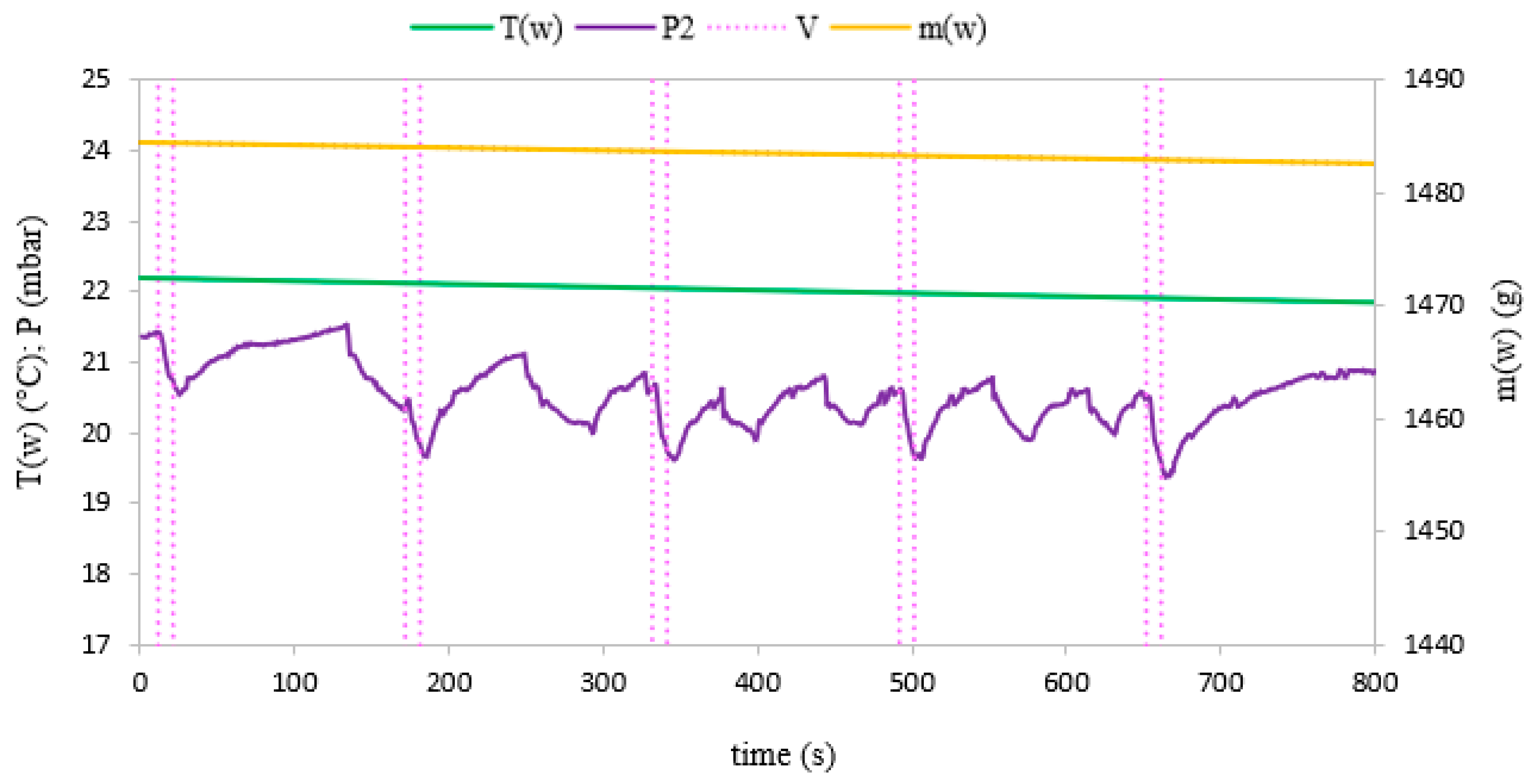
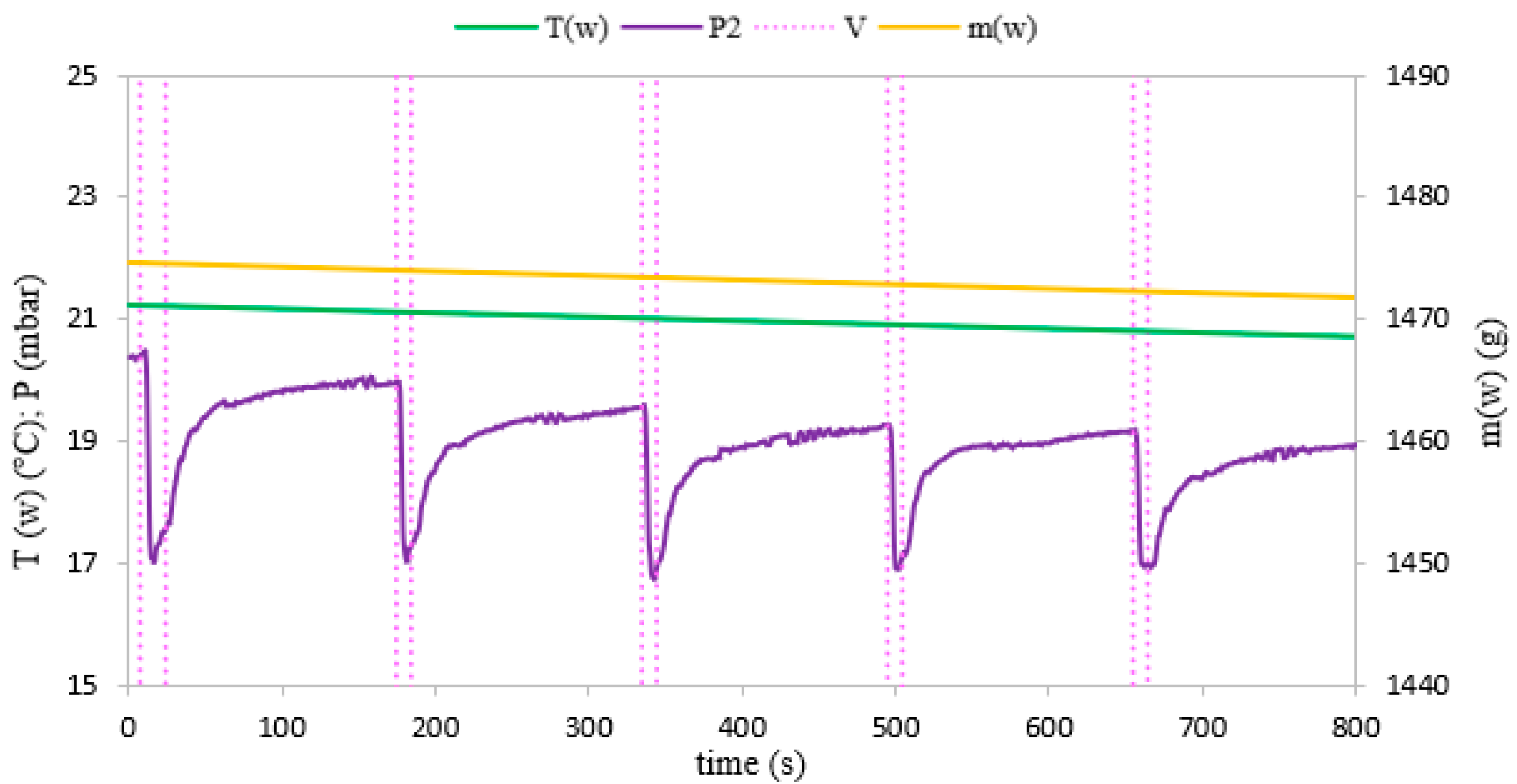
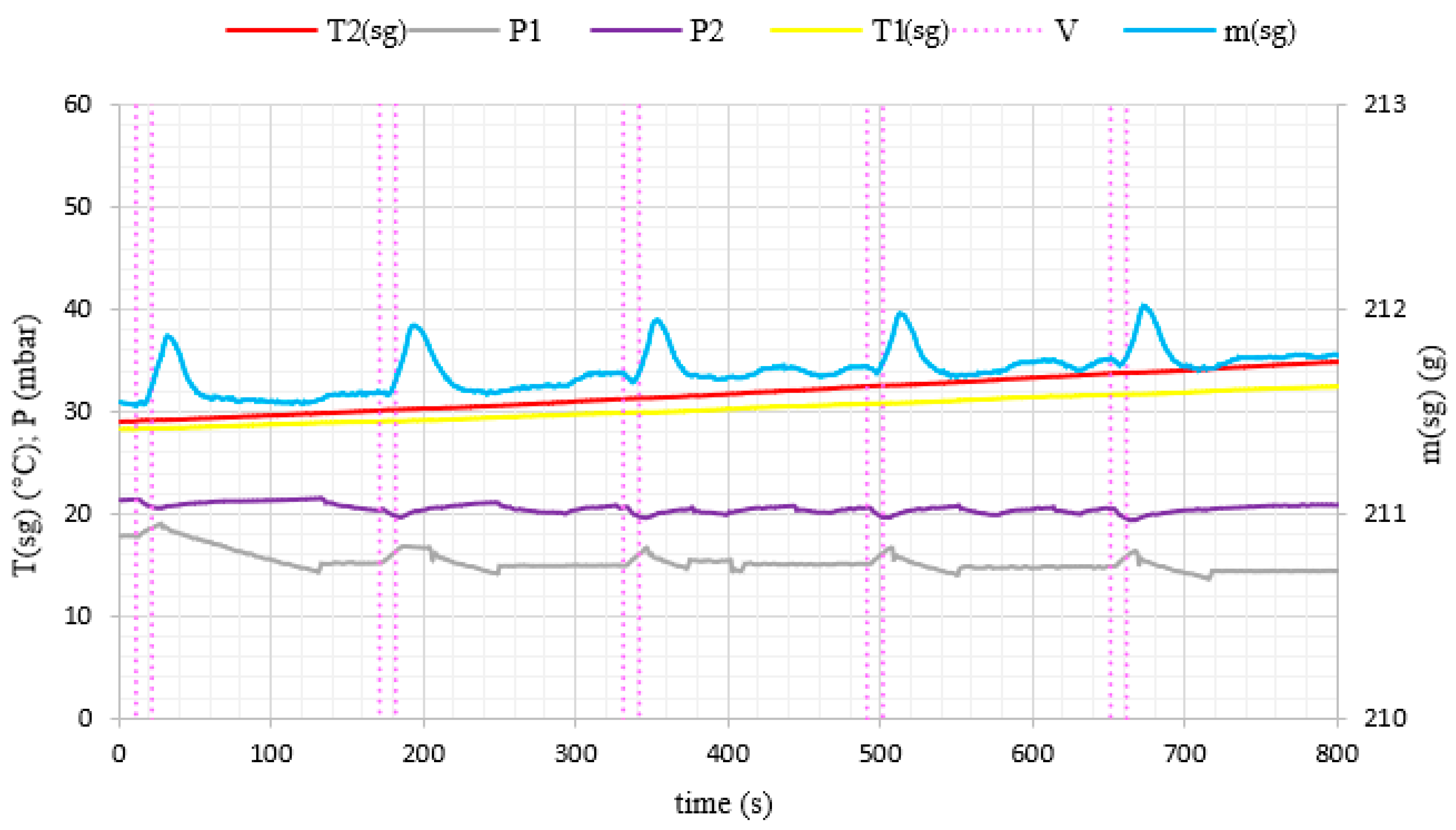
| P1 | absolute pressure in the reaction chamber, mbar |
| P2 | absolute pressure in the evaporator, mbar |
| V | valve |
| Subscripts | |
| ADS | adsorption |
| DES | desorption |
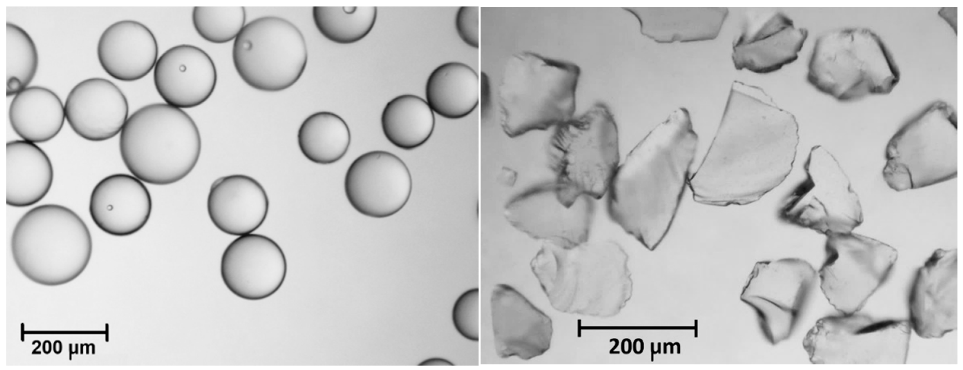
| SG | silica gel |
| w | water |
References
- Andonova, L.B.; Betsill, M.M.; Bulkeley, H. Transnational Climate Governance. Glob. Environ. Polit. 2009, 9, 52–73. [Google Scholar] [CrossRef]
- Alves, F.; Filho, W.L.; Casaleiro, P.; Nagy, G.J.; Diaz, H.; Al-Amin, A.Q.; Guerra, J.B.S.O.D.A.; Hurlbert, M.; Farooq, H.; Klavins, M.; et al. Climate change policies and agendas: Facing implementation challenges and guiding responses. Environ. Sci. Policy 2020, 104, 190–198. [Google Scholar] [CrossRef]
- Kapustenko, P.; Ulyev, L.; Boldyryev, S.; Garev, A. Integration of a heat pump into the heat supply system of a cheese production plant. Energy 2008, 33, 882–889. [Google Scholar] [CrossRef]
- Meyers, S.; Schmitt, B.; Chester-Jones, M.; Sturm, B. Energy efficiency, carbon emissions, and measures towards their improvement in the food and beverage sector for six European countries. Energy 2016, 104, 266–283. [Google Scholar] [CrossRef]
- Wang, Y.; Li, M.; Ji, X.; Yu, Q.; Li, G.; Ma, X. Experimental study of the effect of enhanced mass transfer on the performance improvement of a solar-driven adsorption refrigeration system. Appl. Energy 2018, 224, 417–425. [Google Scholar] [CrossRef]
- Luo, H.; Wang, R.; Dai, Y.; Wu, J.; Shen, J.; Zhang, B. An efficient solar-powered adsorption chiller and its application in low-temperature grain storage. Sol. Energy 2007, 81, 607–613. [Google Scholar] [CrossRef]
- Oliveira, R.G.; Silveira, V., Jr.; Wang, R.Z. Solar-Powered Adsorption Icemaker With Double-Stage Mass Recovery Cycle. Heat Transf. Eng. 2010, 31, 941–949. [Google Scholar] [CrossRef]
- Song, F.; Gong, L.; Wang, L.; Wang, R. Study on gradient thermal driven adsorption cycle with freezing and cooling output for food storage. Appl. Therm. Eng. 2014, 70, 231–239. [Google Scholar] [CrossRef]
- Vasta, S.; Freni, A.; Sapienza, A.; Costa, F.; Restuccia, G. Development and lab-test of a mobile adsorption air-conditioner. Int. J. Refrig. 2012, 35, 701–708. [Google Scholar] [CrossRef]
- Harby, K. Hydrocarbons and their mixtures as alternatives to environmental unfriendly halogenated refrigerants: An updated overview. Renew. Sustain. Energy Rev. 2017, 73, 1247–1264. [Google Scholar] [CrossRef]
- Bruno, J.C.; Valero, A.; Coronas, A. Performance analysis of combined microgas turbines and gas fired water/LiBr absorption chillers with post-combustion. Appl. Therm. Eng. 2005, 25, 87–99. [Google Scholar] [CrossRef]
- Grabowska, K.; Krzywanski, J.; Nowak, W.; Wesolowska, M. Construction of an innovative adsorbent bed configuration in the adsorption chiller—Selection criteria for effective sorbent-glue pair. Energy 2018, 151, 317–323. [Google Scholar] [CrossRef]
- Ge, T.; Wang, R.; Xu, Z.; Pan, Q.; Du, S.; Chen, X.; Ma, T.; Wu, X.; Sun, X.; Chen, J. Solar heating and cooling: Present and future development. Renew. Energy 2018, 126, 1126–1140. [Google Scholar] [CrossRef]
- Jiang, L.; Wang, L.; Liu, C.; Wang, R. Experimental study on a resorption system for power and refrigeration cogeneration. Energy 2016, 97, 182–190. [Google Scholar] [CrossRef] [Green Version]
- Sztekler, K.; Kalawa, W.; Stefanski, S.; Krzywanski, J.; Grabowska, K.; Sosnowski, M.; Nowak, W.; Makowski, M. Using adsorption chillers for utilising waste heat from power plants. Therm. Sci. 2019, 23, 1143–1151. [Google Scholar] [CrossRef] [Green Version]
- Younes, M.M.; El-Sharkawy, I.I.; Kabeel, A.E.; Saha, B.B. A review on adsorbent-adsorbate pairs for cooling applications. Appl. Therm. Eng. 2017, 114, 394–414. [Google Scholar] [CrossRef]
- Liu, Z.L.; An, G.L.; Xia, X.X.; Wu, S.F.; Li, S.; Wang, L.W. The potential use of metal-organic framework/ammonia working pairs in adsorption chillers. J. Mater. Chem. A 2021, 9, 6188–6195. [Google Scholar] [CrossRef]
- De Lange, M.F.; Verouden, K.; Vlugt, T.J.H.; Gascon, J.; Kapteijn, F. Adsorption-Driven Heat Pumps: The Potential of Metal-Organic Frameworks. Chem. Rev. 2015, 115, 12205–12250. [Google Scholar] [CrossRef] [PubMed]
- Calabrese, L.; Bonaccorsi, L.; Bruzzaniti, P.; Frazzica, A.; Freni, A.; Proverbio, E. Adsorption performance and thermodynamic analysis of SAPO-34 silicone composite foams for adsorption heat pump applications. Mater. Renew. Sustain. Energy 2018, 7, 24. [Google Scholar] [CrossRef] [Green Version]
- Brancato, V.; Frazzica, A.; Sapienza, A.; Gordeeva, L.; Freni, A. Ethanol adsorption onto carbonaceous and composite adsorbents for adsorptive cooling system. Energy 2015, 84, 177–185. [Google Scholar] [CrossRef]
- Chan, K.; Chao, C.Y.; Wu, C. Measurement of properties and performance prediction of the new MWCNT-embedded zeolite 13X/CaCl2 composite adsorbents. Int. J. Heat Mass Transf. 2015, 89, 308–319. [Google Scholar] [CrossRef]
- Grabowska, K.; Sztekler, K.; Krzywanski, J.; Sosnowski, M.; Stefanski, S.; Nowak, W. Construction of an innovative adsorbent bed configuration in the adsorption chiller part 2. experimental research of coated bed samples. Energy 2021, 215, 119123. [Google Scholar] [CrossRef]
- Freni, A.; Russo, F.; Vasta, S.; Tokarev, M.; Aristov, Y.I.; Restuccia, G. An advanced solid sorption chiller using SWS-1Ll. Appl. Therm. Eng. 2007, 27, 2200–2204. [Google Scholar] [CrossRef]
- Kulakowska, A.; Pajdak, A.; Krzywanski, J.; Grabowska, K.; Zylka, A.; Sosnowski, M.; Wesolowska, M.; Sztekler, K.; Nowak, W. Effect of Metal and Carbon Nanotube Additives on the Thermal Diffusivity of a Silica Gel-Based Adsorption Bed. Energies 2020, 13, 1391. [Google Scholar] [CrossRef] [Green Version]
- Askalany, A.A.; Henninger, S.K.; Ghazy, M.; Saha, B.B. Effect of improving thermal conductivity of the adsorbent on performance of adsorption cooling system. Appl. Therm. Eng. 2017, 110, 695–702. [Google Scholar] [CrossRef]
- Ilis, G.G.; Mobedi, M.; Ülkü, S. Comparison of Uniform and Non-uniform Pressure Approaches Used to Analyze an Adsorption Process in a Closed Type Adsorbent Bed. Transp. Porous Media 2013, 98, 81–101. [Google Scholar] [CrossRef] [Green Version]
- Krzywanski, J.; Grabowska, K.; Sosnowski, M.; Zylka, A.; Sztekler, K.; Kalawa, W.; Wojcik, T.; Nowak, W. An adaptive neuro-fuzzy model of a re-heat two-stage adsorption chiller. Therm. Sci. 2019, 23, 1053–1063. [Google Scholar] [CrossRef] [Green Version]
- Krzywanski, J. A General Approach in Optimization of Heat Exchangers by Bio-Inspired Artificial Intelligence Methods. Energies 2019, 12, 4441. [Google Scholar] [CrossRef] [Green Version]
- Krzywanski, J.; Grabowska, K.; Herman, F.; Pyrka, P.; Sosnowski, M.; Prauzner, T.; Nowak, W. Optimization of a three-bed adsorption chiller by genetic algorithms and neural networks. Energy Convers. Manag. 2017, 153, 313–322. [Google Scholar] [CrossRef]
- Papakokkinos, G.; Castro, J.; López, J.; Oliva, A. A generalized computational model for the simulation of adsorption packed bed reactors—Parametric study of five reactor geometries for cooling applications. Appl. Energy 2019, 235, 409–427. [Google Scholar] [CrossRef]
- Sosnowski, M. Evaluation of Heat Transfer Performance of a Multi-Disc Sorption Bed Dedicated for Adsorption Cooling Technology. Energies 2019, 12, 4660. [Google Scholar] [CrossRef] [Green Version]
- Kurniawan, A.; Nasruddin; Rachmat, A. CFD Simulation of Silica Gel as an Adsorbent on Finned Tube Adsorbent Bed. E3S Web Conf. 2018, 67, 01014. [Google Scholar] [CrossRef]
- Grabowska, K.; Sosnowski, M.; Krzywanski, J.; Sztekler, K.; Kalawa, W.; Zylka, A.; Nowak, W. Analysis of heat transfer in a coated bed of an adsorption chiller. In Proceedings of the XI International Conference on Computational Heat, Mass and Momentum Transfer, Cracow, Poland, 21–24 May 2018. [Google Scholar]
- Skrobek, D.; Krzywanski, J.; Sosnowski, M.; Kulakowska, A.; Zylka, A.; Grabowska, K.; Ciesielska, K.; Nowak, W. Prediction of Sorption Processes Using the Deep Learning Methods (Long Short-Term Memory). Energies 2020, 13, 6601. [Google Scholar] [CrossRef]
- Yang, W.-C. (Ed.) Handbook of Fluidization and Fluid-Particle Systems, 1st ed.; Taylor & Francis Group: Boca Raton, FL, USA, 2003. [Google Scholar]
- Krzywanski, J.; Urbaniak, D.; Otwinowski, H.; Wylecial, T.; Sosnowski, M. Fluidized Bed Jet Milling Process Optimized for Mass and Particle Size with a Fuzzy Logic Approach. Materials 2020, 13, 3303. [Google Scholar] [CrossRef] [PubMed]
- Krzywanski, J.; Nowak, W. Modeling of bed-to-wall heat transfer coefficient in a large-scale CFBC by fuzzy logic approach. Int. J. Heat Mass Transf. 2016, 94, 327–334. [Google Scholar] [CrossRef]
- Krzywanski, J. Heat Transfer Performance in a Superheater of an Industrial CFBC Using Fuzzy Logic-Based Methods. Entropy 2019, 21, 919. [Google Scholar] [CrossRef] [Green Version]
- Zylka, A.; Krzywanski, J.; Czakiert, T.; Idziak, K.; Sosnowski, M.; Grabowska, K.; Prauzner, T.; Nowak, W. The 4th Generation of CeSFaMB in numerical simulations for CuO-based oxygen carrier in CLC system. Fuel 2019, 255, 115776. [Google Scholar] [CrossRef]
- Idziak, K.; Czakiert, T.; Krzywanski, J.; Zylka, A.; Nowak, W. Studies on Solids Flow in a Cold Model of a Dual Fluidized Bed Reactor for Chemical Looping Combustion of Solid Fuels. J. Energy Resour. Technol. 2019, 142, 1–34. [Google Scholar] [CrossRef]
- Chiang, Y.-C.; Chen, C.-H.; Chiang, Y.-C.; Chen, S.-L. Circulating inclined fluidized beds with application for desiccant dehumidification systems. Appl. Energy 2016, 175, 199–211. [Google Scholar] [CrossRef]
- Zarekar, S.; Buck, A.; Jacob, M.; Tsotsas, E. Reconsideration of the hydrodynamic behavior of fluidized beds operated under reduced pressure. Powder Technol. 2016, 287, 169–176. [Google Scholar] [CrossRef]
- Zarekar, S.; Bück, A.; Jacob, M.; Tsotsas, E. Numerical study of the hydrodynamics of fluidized beds operated under sub-atmospheric pressure. Chem. Eng. J. 2019, 372, 1134–1153. [Google Scholar] [CrossRef]
- Krzywanski, J.; Grabowska, K.; Sosnowski, M.; Zylka, A.; Kulakowska, A.; Czakiert, T.; Sztekler, K.; Wesolowska, M.; Nowak, W. Heat Transfer in Adsorption Chillers with Fluidized Beds of Silica Gel, Zeolite, and Carbon Nanotubes. Heat Transf. Eng. 2021, 43, 1–15. [Google Scholar] [CrossRef]
- Krzywanski, J.; Grabowska, K.; Sosnowski, M.; Zylka, A.; Kulakowska, A.; Czakiert, T.; Sztekler, K.; Wesolowska, M.; Nowak, W. Heat transfer in fluidized and fixed beds of adsorption chillers. E3S Web Conf. 2019, 128, 01003. [Google Scholar] [CrossRef]
- Sztekler, K.; Kalawa, W.; Nowak, W.; Mika, L.; Gradziel, S.; Krzywanski, J.; Radomska, E. Experimental Study of Three-Bed Adsorption Chiller with Desalination Function. Energies 2020, 13, 5827. [Google Scholar] [CrossRef]
- Sztekler, K.; Kalawa, W.; Nowak, W.; Mika, Ł.; Krzywański, J.; Grabowska, K.; Sosnowski, M.; Al-Harbi, A.A. Performance Evaluation of a Single-Stage Two-Bed Adsorption Chiller with Desalination Function. J. Energy Resour. Technol. 2021, 143, 1–22. [Google Scholar] [CrossRef]
- Rogala, Z.; Kolasiński, P.; Błasiak, P. The Influence of Operating Parameters on Adsorption/Desorption Characteristics and Performance of the Fluidised Desiccant Cooler. Energies 2018, 11, 1597. [Google Scholar] [CrossRef] [Green Version]
- Rogala, Z.; Kolasiński, P.; Gnutek, Z. Modelling and experimental analyzes on air-fluidised silica gel-water adsorption and desorption. Appl. Therm. Eng. 2017, 127, 950–962. [Google Scholar] [CrossRef]
- Yaman, O.; Kulah, G.; Koksal, M. Surface-to-bed heat transfer for high-density particles in conical spouted and spout–fluid beds. Particuology 2019, 42, 35–47. [Google Scholar] [CrossRef]
- Olazar, M.; Lopez, G.; Altzibar, H.; Aguado, R.; Bilbao, J. Minimum spouting velocity under vacuum and high temperature in conical spouted beds. Can. J. Chem. Eng. 2009, 87, 541–546. [Google Scholar] [CrossRef]
- Win, K.K.; Nowak, W.; Matsuda, H.; Hasatani, M.; Bis, Z.; Krzywanski, J.; Gajewski, W. Transport Velocity of Coarse Particles in Multi-Solid Fluidized Bed. J. Chem. Eng. Jpn. 1995, 28, 535–540. [Google Scholar] [CrossRef] [Green Version]
- Grace, J.R.; Bi, X.; Ellis, N. (Eds.) Essentials of Fluidization Technology; Wiley-VCH: Weinheim, Germany, 2020. [Google Scholar]

Publisher’s Note: MDPI stays neutral with regard to jurisdictional claims in published maps and institutional affiliations. |
© 2021 by the authors. Licensee MDPI, Basel, Switzerland. This article is an open access article distributed under the terms and conditions of the Creative Commons Attribution (CC BY) license (https://creativecommons.org/licenses/by/4.0/).
Share and Cite
Grabowska, K.; Zylka, A.; Kulakowska, A.; Skrobek, D.; Krzywanski, J.; Sosnowski, M.; Ciesielska, K.; Nowak, W. Experimental Investigation of an Intensified Heat Transfer Adsorption Bed (IHTAB) Reactor Prototype. Materials 2021, 14, 3520. https://doi.org/10.3390/ma14133520
Grabowska K, Zylka A, Kulakowska A, Skrobek D, Krzywanski J, Sosnowski M, Ciesielska K, Nowak W. Experimental Investigation of an Intensified Heat Transfer Adsorption Bed (IHTAB) Reactor Prototype. Materials. 2021; 14(13):3520. https://doi.org/10.3390/ma14133520
Chicago/Turabian StyleGrabowska, Karolina, Anna Zylka, Anna Kulakowska, Dorian Skrobek, Jaroslaw Krzywanski, Marcin Sosnowski, Katarzyna Ciesielska, and Wojciech Nowak. 2021. "Experimental Investigation of an Intensified Heat Transfer Adsorption Bed (IHTAB) Reactor Prototype" Materials 14, no. 13: 3520. https://doi.org/10.3390/ma14133520
APA StyleGrabowska, K., Zylka, A., Kulakowska, A., Skrobek, D., Krzywanski, J., Sosnowski, M., Ciesielska, K., & Nowak, W. (2021). Experimental Investigation of an Intensified Heat Transfer Adsorption Bed (IHTAB) Reactor Prototype. Materials, 14(13), 3520. https://doi.org/10.3390/ma14133520