Abstract
The study aims to investigate the fire performance of reinforced concrete (RC) slab fabricated from high volume fly ash inclusion with nano-silica (HVFANS) under ISO 834 load curve. The HVFANS concrete slab with dimensions of 1850 mm × 1700 mm × 200 mm was tested via an electrical furnace under an exposing temperature of 1100 °C for 120 min. The slab behaviour was evaluated in terms of residual compressive strength, temperature distribution along its thickness, spalling, and cracks. The results revealed that the slab was capable of maintaining 62.19% of its original compressive strength at room temperature after exposure to the above temperature. Moreover, the distribution of temperature revealed that the temperature of concrete cover and bottom reinforcement was less than 300 °C with a maximum spalling depth of 11 mm within the temperature range of 680 to 840 °C. Furthermore, the thermal conductivity index (K) of the HVFANS concrete was determined, and results indicated that thermal conductivity equalled 0.35 W/mK which is considered low, as compared with other concretes tested in current and previous studies.
1. Introduction
Fire represents one of the most severe conditions to which structures might be subjected as the instant the catastrophic fire of the Mont Blanc tunnel in 1999s which caused 39 deaths and serious damage to the tunnel lining structure that cost €206 to €250 million for restoration work [1,2,3,4]. In the event of a fire inside a structure, for example, a tunnel, the temperature may rise extremely fast within 30 min and reach up to 1200 °C according to temperature–time curve for road tunnels in Germany Zusätzliche Technische Vertragsbedingungen und Richtlinien für Ingenieurbauten (ZTV-ING) [5]. Therefore, providing an appropriate fire safety measure for concrete members is an important aspect of design.
Engineering structures are usually constructed from normal strength concrete (NSC) or high strength concrete (HSC) fabricated by various procedures [6,7]. Studies [8,9,10,11] revealed that the high strength concrete (HSC) lost about 40% of its room compressive strength at the intermediate temperatures range between 100 to 400 °C, while the normal strength concrete (NSC) lost approximately 20 to 30% of its strength at similar temperatures. Moreover, the laboratory tests indicated that the explosive spalling of HSC was higher than NSC due to its low permeability. This tendency means that HSC structural elements might be more susceptible to lose the concrete cover that provides thermal protection of the steel reinforcement. Consequently, it is recommended that the temperature of steel reinforcements should not exceed a range of 250 to 300 °C [12]. In this context, the HSC structures are usually protected against fire by using passive and active protection methods. Active methods, such as water sprinkler systems, are used to remove the heat from the void and cooling the structure members. In the passive protection method, the structures are usually protected by using insulating materials to restrict the flow of heat into the structure. Studies concur that adding polypropylene fibre (PPF) with a ratio between 0.5 to 3 kg/m3 could significantly improve the spalling resistant of HSC due to the melting of PPF between 160 to 170 °C and evaporation at 350 °C caused new pores which work as channels to relieve the internal energy of water vapour pressure [13,14,15,16,17,18].
Nowadays, the massive production of Portland cement resulted in significant growth in environmental pollution. Several reports stated that the manufacturing of one ton Portland cement liberated around one ton of gases to the atmosphere, mainly composed of carbon dioxide CO2 which contributed about 65% of global warming [19,20,21,22]. Thus, researchers suggested alternatives binders as instant fly ash (FA), slag, nanomaterial, metakaolin, etc. to decrease the reliance on Portland cement in constructions [23].
In this field, several scholars aimed to use fly ash which is a by-product of thermal electric plants as a partial replacement of Portland cement due to its beneficial effects on the concrete behaviour and low cost. Moreover, they intensively studied the effects of using FA on the thermal properties of concrete. Bentz et al. [24] reported that the increase of FA content significantly reduced the thermal conductivity of concrete, while Gifford and Ward [25] stated that the high quantities of FA slightly decreased the thermal expansion of concrete. Rashad [26,27] noted a higher relative compressive strength for the concrete containing 70% of FA after being exposed to temperatures of 400, 600, 800, and 1000 °C for 2 h, compared to the Plain Concrete (PC). Shang and Yi 2013 [28] studied the thermal properties of HSC containing 20 and 21% of fly ash with compressive strengths of 50 and 60 MPa, respectively. The results revealed that both concretes were capable of maintaining 80.4 and 81.5% of their original strengths after being exposed to 500 °C.
The main shortcoming of using high volumes of fly ash in concrete is the sharp reduction in the compressive strength at early ages as indicated by several researchers [29,30,31,32]. Therefore, nano-silica (NS) was broadly used to improve the mechanical properties of concrete containing a high volume of fly ash (HVFA), particularly at an early age, due to its pozzolanic reactivity besides the pore-filling effect. Li [33] stated that replacing 4% of NS in concrete contained 50% of FA could enhance the compressive strength by 68.57, 39.34, 18.72, and 7.58% at curing ages of 7, 28, 56, and 112 days, respectively. Ibrahim [34] replaced the HVFA concrete containing 55% of FA with colloidal NS of 2.5, 5, and 7.5% and observed that the compressive strength increased with the increase of NS content in all the investigated cases at age of 28 days.
Moreover, researchers noted that the addition of NS considerably improved the thermal stability of the HVFA concrete. Lim et al. [35] indicated that samples containing Nano silica showed lesser strength loss after being exposed to elevated temperatures at 500 °C, as compared with samples contained silica fume. Mortar containing HVFA showed higher residual strength after exposure to 700 °C, and dehydration of C–S–H produced calcium silicate which acts as a new binding material to retain residual strength [36]. Ibrahim [34] reported that high volume fly ash inclusion with nano-silica (HVFANS) concrete can be used as a fireproof material under temperatures reach up to 700 °C, whereas the HVFANS concrete was able to maintain about 94.54% of its room compressive strength after exposing to a temperature of 700 °C.
According to the above results, this study aims to test the fire performance of HVFANS concrete as a part of the structure to increase the confidence of using this type of concrete in engineering structures. Therefore, a concrete slab with dimensions of 1850 mm × 1700 mm × 200 mm was fabricated according to the mix proportions recommended by Ibrahim [34] and tested under temperatures reach up to 1100 °C via an electric furnace based on ISO 834 [37] fire load curve during the time of 120 min.
2. Materials and Methods
2.1. Materials
The Portland cement (Type I) manufactured by Tasek Cement Company (Ipoh, Perak, Malaysia) according to Malaysian standard (MS 522) [38] was used. The Fly ash was collected from Jimah Power Plant located in Malaysian Port Dickson (Negeri Sembilan, Malaysia) and categorised as class F based on British Standard (BS EN 450: 2005), which specified that the sum of silicon dioxide SiO2, aluminium oxide Al2O3, and ferric oxide Fe2O3 must be more than 70% [39]. The chemical component details of cement and fly ash are described in Table 1 [40].

Table 1.
Chemical detail of cement and fly ash materials (Adapted from [40]).
Colloidal nano-silica (NS) type Cembinder W8 provided by AkzoNobel Company (Haman-gun, Gyeongsangnam-do, South Korea) was used to enhance the early compressive strength of concrete, thereby shortening the setting time of the cement slurry [36]. The surface area of NS particles was equal to 80 m2/g, with an average size of 35 nm, and a silica concentration of 50%, with a bulk density of 1050 kg/m3 and pH of 10. Natural river sand was used as a fine aggregate which could pass through a 4.75 mm sieve size with a bulk specific gravity of 2.53 and fineness modulus of 2.98 [41,42]. The loose and compacted bulk densities of fine aggregate were 1510.18 and 1721.83 kg/m³, respectively [43]. Crushed granite coarse aggregate provided from local sources with a maximum size of 10 mm and bulk specific gravity of 2.07 was used in the mix design. These fibres have a white colour with a melting point that ranges between 160 to 170 °C and tensile strength of 0.36 kN/mm2.
Superplasticiser type (Darex Super 20) manufactured by GCP Applied Technologies company (Selangor, Malaysia) was added with a dosage of 1% of cementitious materials weight to provide the required workability and improve the compressive strength of concrete via decreasing the amount of water in the mixture due to the existence of naphthalene sulphonate [44,45,46]. White-colour fibrillated polypropylene fibres (PPF), provided by Timuran Company (Selangor, Malaysia) with a dosage of 1 kg/m3 of concrete volume and length of 12 mm with a specific gravity of 0.9, were added to increase the ductility of concrete and reduce the surface spalling, as recommended in prior studies [13,14,15,16,17].
2.2. Concrete Mixture Design
The mixture proportions of plain concrete (PC) and HVFANS concrete slabs with a target compressive strength of 60 MPa were selected based on the American Concrete Institute Standard (ACI 211.4R-93) [47], as described in Table 2. The percentages of FA and NS as cement replacement equalled 52.5% and 2.5%, respectively, with a water-to-cementitious material ratio (w/c + p) of 0.29 [36].
Table 2.
PC (Plain Concrete) and HVFANS (high volume fly ash inclusion with nano-silica) concrete mixing proportions (kg/m3).
The mixing of materials based on ASTM C192 [48] led to the formation of cement balls, mainly in the case of HVFNS concrete, since the mixture was stiff. Therefore, the sand and a portion of gravel with cement and fly ash were initially mixed. Afterward, the nano-silica and water were added. The slump test was carried out before adding the superplasticiser and maintained between 25 and 50 mm (true slump). Lastly, the rest of the gravel with PPF was added. Three concrete cubes, each with a size of 150 mm × 150 mm × 150 mm, were cast to determine the required compressive strength before casting the concrete slab. The samples were covered by a plastic membrane, to avoid moisture evaporation, and de-moulded after 48 h. The results indicated that the average value of compressive strength of the concrete was 62.7 MPa after 28 days.
2.3. Concrete Slab Fabrication
Two slabs were fabricated from plain concrete (PC) and HVFANS concrete, each with a size of 1850 mm × 1700 mm × 200 mm, according to the European Federation of National Associations Representing Concrete (EFNARC) [49]. During the test, the specimen dimensions were larger than the size of the furnace opening to ensure a stable position and prevent heat from escaping from the sides of the slab. Bar reinforcements with a diameter of 12 mm each and at a spacing of 100 mm × 200 mm were used. Four thermocouples manufactured by RS Components Sdn Bhd P.O (Kuala Lumpur, Malaysia) type (K), each with a diameter of 3 mm, were used and placed at depths of 30, 60, 90, and 200 mm from the bottom surface of the concrete slab. The thermocouples were installed during the casting of the slab to ensure high coupling efficiency, avoid air space, and provide full physical contact between the thermocouple and concrete.
2.4. Furnace Test
The fire test was conducted by using a medium-scale furnace provided by Forest Research Institute Malaysia (FRIM) (Kepong, Selangor, Malaysia) with dimensions of 1.5 m × 1.5 m × 1.5 m at a temperature of 1100 °C, as shown in Figure 1.
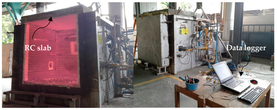
Figure 1.
Medium-scale furnace.
The heat within the chamber was controlled at the standard heating temperature according to the ISO 834 fire curve. The temperature was measured at 100 mm from the furnace wall to ensure compliance with the fire load curve. The opening of the furnace was wrapped by a fireclay rock wool sheet to avoid thermal loss. The concrete slab was placed horizontally at the top of the furnace opening. The test setup of the fire test included the position of the concrete slab and thermocouple wire connected to the data logger and computer, as shown in Figure 2.
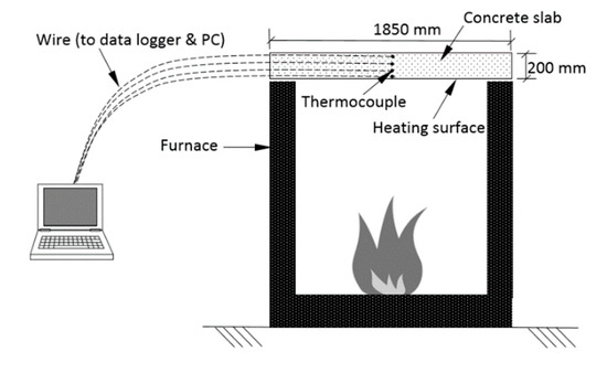
Figure 2.
Fire test setup.
Based on ISO 834-1 [41], the temperature increment within the furnace is described by the following equation:
where t is the time in min, and T(t) is the gas temperature within the furnace in °C. The measured time–temperature curve in the furnace chamber, as compared with ISO 834 curve, is presented in Figure 3. A heating duration of 120 min was used during the test to simulate a real fire scenario in tunnels according to EFNARC guidelines [49]. The fire test started at 50 °C and terminated after achieving the required fire load curve. The cooling phase was monitored based on the specified fire load. The furnace was shut down after 120 min and the specimen was left into the furnace to cool down and was removed after 1 h.
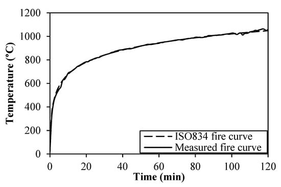
Figure 3.
Time history of the recorded fire curves.
2.5. Thermal Conductivity Test
The thermal conductivity test of PC and HVFANS concrete was carried out by using the λ-Meter EP500e tool manufactured by Lambda-Meßtechnik GmbH Dresden (Dresden, Germany) based on Malaysian Standard ISO 8302 [41]. According to the guidelines, the recommended thickness of the measured specimens should range between 10 to 200 mm to exclude the influence of heat radiation. Accordingly, the specimen size of 500 mm × 500 mm with a measured thickness of 52.93 mm and density of 2300 kg/m3 was used and prepared with a flat and dry surface. The thermal resistance (R) and thermal conductivity (K) are computed using the following equations:
where ΔT is the temperature difference, A is the surface area, Q is the total heat supplied, and d is the specimen thickness. The measurement was computed at a single temperature of 20 °C at a temperature difference of 15 K.
2.6. Coring Test
The coring tests for PC and HVFANS concrete slabs were conducted before and after the fire test according to ASTM C42 guidelines which recommended that the ratio of specimen length to its diameter (L/D) should range between 1.9 to 2.1 [50]. Therefore, the cylindrical drilled cores specimens with dimensions of (50 mm × 100 mm were tested. A total of 12 cores were drilled, whereas 4 cores were used to evaluate the percentage of free moisture content and the rest were utilised to determine the residual compressive strength and density of both slabs.
3. Results and Discussion
3.1. Results of Thermal Conductivity Test
The thermal conductivity of PC and HVFANS concrete was determined. The results demonstrated that the HVFANS concrete had a lower thermal conductivity equal to 0.35 W/mK, as compared with PC, which recorded 0.8 W/mK at similar test circumstances. This behaviour might be attributed to the existence of high-volume fly ash, whereas Bentz [24] recorded a significant reduction in the thermal conductivity, by 19%, for HVFA concrete that contained 75% fly ash, as compared with conventional concrete. Moreover, using nano-silica in concrete mixture decreased the pore size and total porosity of the concrete due to the large surface area production that may speed up the rate of the pozzolanic reaction and cause a lower conductivity [36].
3.2. Furnace Test
3.2.1. Temperature Distribution along the Slab Thickness
During the fire test, the thermal distribution of PC and HVFANS concrete slabs was recorded via four thermocouples located at different depths from the heated surface, as shown in Figure 4. At depth 30 mm, the HVFANS slab showed lower thermal distribution at all the time intervals, as compared to the PC slab, particularly after 10 to 30 min, by −51% and −44.08%, respectively. These differences were reduced with the increase of time and recorded −1.56% after 2 h of fire with a maximum temperature of 531 °C. At the depth of 60 mm, once again the HVFANS slab showed lower temperature magnitudes in all the time periods with a maximum temperature of 285 °C after 2 h. This behaviour may be attributed to the low thermal conductivity of HVFANS concrete, as compared to PC. At the depth of 90 mm, the recorded temperature of the HVFANS slab was lower than the PC slab by −13.88% after 30 min. A constant temperature equal to 120 °C was noted during 30 to 70 min for the HVFANS slab, as a result of the evaporation of free water and chemically bonded water of the calcium silicate hydrate (C–S–H) from the concrete slab [51]. The temperature started to increase slightly after 73 min until it reached up to 211 °C within 120 min. Finally, at the depth of 200 mm, the temperatures were considerably reduced for both slabs; nevertheless, the HVFANS slab still showed a lower thermal distribution at all time intervals with a maximum difference of −21.14% after 1 h and the highest temperature of 76 °C after 2 h, as shown in Figure 4d.
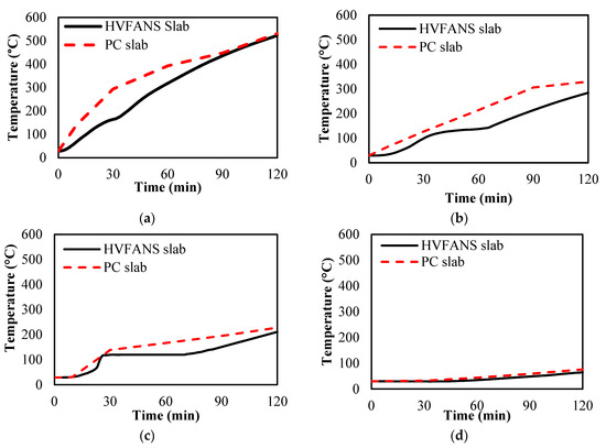
Figure 4.
Temperature distribution of PC and HVFANS slabs at depths: (a) 30 mm; (b) 60 mm; (c) 90 mm; (d) 200 mm, from the exposed surface.
Further comparison was conducted with previous slabs tested by other scholars under similar temperature magnitudes, reaching up to 1100 °C, which particularly occurred in concrete tunnels [52,53]. The results proved that HVFANS concrete slab had better performance and recorded lower temperatures particularly at a depth of 60 mm which is considered the standard depth of concrete cover and reinforcement location for these structures, as shown in Table 3.
Table 3.
Comparison of temperature recorded at depth 60 mm after 2 h heating in previous studies.
3.2.2. Concrete Spalling
The concrete spalling effect was carefully observed and recorded during the furnace test for both concrete slabs. The results showed a spalling location on the heated surface of the HVFANS concrete slab with a maximum depth of 11 mm and area of 34.3% within the temperature range of 680 to 840 °C, while the PC slab recorded the highest spalling depth of 19 mm within a lower temperature range of 480 to 700 °C, as shown in Figure 5 and Figure 6. Moreover, the outcomes were compared with previous studies using slabs fabricated from different materials and were tested by using an ISO 834 fire curve; once again, the HVFANS concrete slab showed a superior behaviour, as compared with these slabs [54,55,56,57]. No concrete spalling occurred in both concrete slabs during the cooling period. Ali et al. [58] indicated three types for concrete spalling, namely, minor, major, and severe, according to the depth of spalling. Accordingly, the spalling of HVFANS concrete could be considered minor since the fire did not reach the reinforcement depth. High-strength concrete usually contains vapour pressure in its pores and also suffers from large thermal stress. In this study, using PPF and small-size aggregate (10 mm) significantly relieved the thermal expansion and stresses induced in concrete, as reported by Maraveas and Vrakas [59].
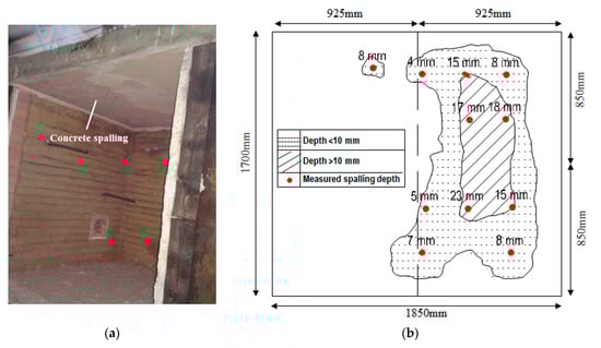
Figure 5.
Concrete spalling: (a) visual appearance and (b) coverage area.
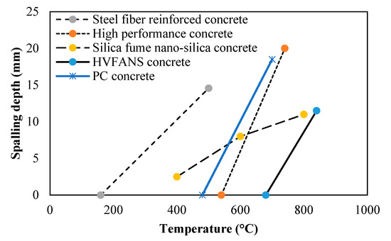
Figure 6.
Concrete spalling depth at different temperatures [53,54,56].
3.2.3. Moisture Content
The moisture content of both concrete slabs was recorded before and after the fire test. The average records of the cores for PC and HVFANS concrete before the fire were 4.95 and 5.97%, respectively. The moisture content was reduced after firing for both concrete slabs and recorded 4.10 and 5.40%. The water was vapoured out from visible cracks distributed along the width of the unexposed concrete slab surface as well as along the installation holes of the thermocouples and reinforcement within the time range between 20 to 100 min. Similar phenomena were observed by previous scholars [56,60,61,62]. Zeiml et al. [63] indicated that the cracks occurred because of the tensile thermal stress and non-uniform temperature distribution. Using nano-silica reduced the crack formation on the slab surface [36].
3.2.4. Residual Compressive Strength and Density
The average compressive strength of two cylindrical coring samples was recorded before and after the firing of PC and HVFANS concrete slabs. The results revealed that the compressive strength of both slabs was decreased after exposure to elevated temperatures reaching up to 1100 °C. However, the HVFANS slab showed superior fire resistance and recorded the lowest reduction, by −37.81%, as compared with the PC slab which recorded a reduction of −63.42%, as shown in Table 4.
Table 4.
Compressive strength ( ) of PC and HVFANS slabs before and after firing.
Moreover, the reduction and relative compressive strength (RCS) was computed for both concrete slabs by the following equations:
The results proved that the HVFANS slab had the highest RCS by 62.19%, as compared with PC which recorded only 36.58%. Ibrahim et al. [36] conducted an X-ray diffractometry (XRD) test and stated that the high residual strength at temperatures above 700 °C for the concrete containing similar proportions of fly ash and nano-silica, shown in Table 1, may be attributed to the formation of new silicate compounds from the reaction of the fly ash and nano-silica which caused a significant reduction in calcium silicate. Moreover, Ibrahim et al. [36] observed superior performance for these in terms of the pore size distribution and recorded a higher decrease, as compared to control samples, because of the great stability of the calcium silicate hydrate, as indicated in the scanning electron microscope (SEM) test.
From the above core samples, the density of PC and HVFANS concrete slabs were determined before and after the fire test according to ASTM C138 [64]. The results proved that the density of both slabs was reduced at high temperatures; however, the HVFANS slab showed better performance and recorded a reduction of −7.93%, as shown in Table 5.
Table 5.
Density ( ) (kg/m3) of PC and HVFANS slabs before and after firing.
3.2.5. Steel Bearing Capacity
A rebar tensile test was performed to determine the yield strength of steel reinforcement before and after the fire test. The yield strength of mild steel reinforcement used in the HVFANS slab almost remained constant, with a value of 276.29 MPa between temperatures of 28 to 283 °C, as shown in Figure 7. However, it was slightly decreased by 3.4% and recorded 266.68 MPa at a temperature of 300 °C.
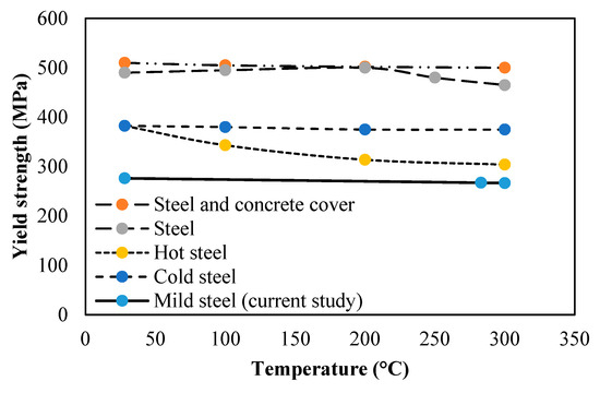
Figure 7.
Yield strength of reinforcement at different temperatures [65,66].
The mechanical properties of the steel reinforcement deteriorated when subjected to temperatures exceeding 300 °C [59]. The results proved that the cover of 60 mm used in the HVFANS concrete slab was capable to withstand elevated temperatures reaching up to 1100 °C, while this cover was not sufficient to maintain the temperature of rebar less than 300 °C, and the temperature was able to reach into the slab reinforcement and caused severe damage. Unluoglu et al. [65] and Naus [66] observed similar deterioration in the reinforcement within various percentages that ranged between 2.0 and 20.5% and stated that a thicker concrete cover could reduce the temperature of reinforcement and delay its failure which mainly depended on the peak temperature and fire duration.
4. Conclusions
The results can be summarised as follows:
- Visual inspection showed that minor spalling occurred in the concrete slab with a maximum depth of 11 mm at a duration between 10 to 30 min within a temperature range of 680 to 840 °C while severe spalling occurred in the PC slab with a depth of 19 mm within temperatures range of 480 to 700 °C;
- The coring test indicated that the residual compressive strength of the HVFANS concrete slab was reduced by −37.81% from its original compressive strength under 1100 °C, while the strength of the PC slab was reduced by −63.42% under similar circumstances;
- The temperature distribution along slab thickness indicated that the HVFANS concrete had superior performance and recorded lower temperatures than the PC slab under all the investigated depths;
- The yield strength of mild steel reinforcement into the HVFANS concrete slab almost remained constant with a value of 276.29 MPa between temperatures of 28 to 285 °C, while the strength of similar reinforcement into the PC slab was reduced to 216.29 MPa under identical conditions;
- The thermal conductivity test results proved that HVFANS concrete had excellent fire resistance with a maximum thermal conductivity value (K) of 0.35 W/mK, which is considered lower than other concrete types such as NSC and HVFA concrete types.
According to the above results, the HVFANS concrete can provide superior fire protection, as compared to plain concrete, for the structural members exposed to massive temperatures reaching up to 1100 °C. Therefore, future studies are recommended to present further information about this type of concrete.
Author Contributions
Conceptualisation, M.H.M.; methodology, M.H.M. and N.A.M.R.; investigation, M.H.M. and N.A.M.R.; formal analysis, M.H.M. and N.A.M.R.; supervision, R.H. and A.A.M.; project administration, R.H. and A.A.M.; Funding acquisition, R.H.; resources, R.H. and A.A.M.; data curation, M.H.M. and N.A.M.R.; visualisation, M.H.M. and N.A.M.R.; writing—original draft preparation, M.H.M.; writing—review and editing, M.H.M. All authors have read and agreed to the published version of the manuscript.
Funding
The authors would thank Universiti Kebangsaan Malaysia (UKM) for providing financial support through project DIP-2019-002.
Institutional Review Board Statement
Not applicable.
Informed Consent Statement
Not applicable.
Data Availability Statement
All the data is available within the manuscript.
Conflicts of Interest
The authors declare that they have no conflict of interest.
References
- Larsson, K. Fires in Tunnels and Their Effect on Rock: A Review; Luleå Tekniska Universitet: Luleå, Sweden, 2006. [Google Scholar]
- Ren, R.; Zhou, H.; Hu, Z.; He, S.; Wang, X. Statistical analysis of fire accidents in chinese highway tunnels 2000–2016. Tunn. Undergr. Space Technol. 2019, 83, 452–460. [Google Scholar] [CrossRef]
- Mussa, M.H.; Mutalib, A.A.; Hamid, R.; Naidu, S.R.; Radzi, N.A.M.; Abedini, M. Assessment of damage to an underground box tunnel by a surface explosion. Tunn. Undergr. Space Technol. 2017, 66, 64–76. [Google Scholar] [CrossRef]
- Mussa, M.H.; Mutalib, A.A.; Hamid, R.; Raman, S.N. Blast damage assessment of symmetrical box-shaped underground tunnel according to peak particle velocity (ppv) and single degree of freedom (sdof) criteria. Symmetry 2018, 10, 158. [Google Scholar] [CrossRef]
- Kaundinya, I. Protection of Road Tunnel Linings in Cases of Fire. In Proceedings of the FEHRL/FERSI/ECTRI Young Researchers Seminar, Brno, Czech Republic, 28 May 2007. [Google Scholar]
- Chalangaran, N.; Farzampour, A.; Paslar, N. Nano silica and metakaolin effects on the behavior of concrete containing rubber crumbs. CivilEng 2020, 1, 264–274. [Google Scholar] [CrossRef]
- Hosseini, S.A. Application of various types of recycled waste materials in concrete constructions. Adv. Concr. Constr. 2020, 9, 479–489. [Google Scholar]
- Krishna, D.A.; Priyadarsini, R.; Narayanan, S. Effect of elevated temperatures on the mechanical properties of concrete. Procedia Struct. Integr. 2019, 14, 384–394. [Google Scholar] [CrossRef]
- Kodur, V. Properties of concrete at elevated temperatures. ISRN Civil Eng. 2014. [Google Scholar] [CrossRef]
- Phan, L.T.; Carino, N.J. Review of mechanical properties of hsc at elevated temperature. J. Mater. Civ. Eng. 1998, 10, 58–65. [Google Scholar] [CrossRef]
- Novak, J.; Kohoutkova, A. Mechanical properties of concrete composites subject to elevated temperature. Fire Saf. J. 2018, 95, 66–76. [Google Scholar] [CrossRef]
- Kolymbas, D. Tunnelling and Tunnel Mechanics: A Rational Approach to Tunnelling; Springer Science & Business Media: New York, NY, USA, 2005. [Google Scholar]
- Ríos, J.D.; Cifuentes, H.; Leiva, C.; García, C.; Alba, M.D. Behavior of high-strength polypropylene fiber-reinforced self-compacting concrete exposed to high temperatures. J. Mater. Civ. Eng. 2018, 30, 04018271. [Google Scholar] [CrossRef]
- Amancio, F.A.; de Carvalho Rafael, M.F.; de Oliveira Dias, A.R.; Cabral, A.E.B. Behavior of concrete reinforced with polypropylene fiber exposed to high temperatures. Procedia Struct. Integr. 2018, 11, 91–98. [Google Scholar] [CrossRef]
- Eidan, J.; Rasoolan, I.; Rezaeian, A.; Poorveis, D. Residual mechanical properties of polypropylene fiber-reinforced concrete after heating. Constr. Build. Mater. 2019, 198, 195–206. [Google Scholar] [CrossRef]
- Yan, P.; Chen, B.; Afgan, S.; Haque, M.A.; Wu, M.; Han, J. Experimental research on ductility enhancement of ultra-high performance concrete incorporation with basalt fibre, polypropylene fibre and glass fibre. Constr. Build. Mater. 2021, 279, 122489. [Google Scholar] [CrossRef]
- Madhavi, T.C.; Raju, L.S.; Mathur, D. Polypropylene fiber reinforced concrete-a review. Int. J. Emerg. Technol. Adv. Eng. 2014, 4, 114–118. [Google Scholar]
- Saadun, A.; Mutalib, A.A.; Hamid, R.; Mussa, M.H. Behaviour of polypropylene fiber reinforced concrete under dynamic impact load. J. Eng. Sci. Technol. 2016, 11, 684–693. [Google Scholar]
- Farzampour, A. Compressive Behavior of Concrete under Environmental Effects. In Compressive Strength of Concrete; IntechOpen: Rijeka, Croatia, 2019; pp. 1–14. [Google Scholar]
- Wu, M.; Zhang, Y.; Ji, Y.; Liu, G.; Liu, C.; She, W.; Sun, W. Reducing environmental impacts and carbon emissions: Study of effects of superfine cement particles on blended cement containing high volume mineral admixtures. J. Clean. Prod. 2018, 196, 358–369. [Google Scholar] [CrossRef]
- Li, Y.; Liu, Y.; Gong, X.; Nie, Z.; Cui, S.; Wang, Z.; Chen, W. Environmental impact analysis of blast furnace slag applied to ordinary portland cement production. J. Clean. Prod. 2016, 120, 221–230. [Google Scholar] [CrossRef]
- Mussa, M.H.; Abdulhadi, A.M.; Abbood, I.S.; Mutalib, A.A.; Yaseen, Z.M. Late age dynamic strength of high-volume fly ash concrete with nano-silica and polypropylene fibres. Crystals 2020, 10, 243. [Google Scholar] [CrossRef]
- Flower, D.J.; Sanjayan, J.G. Green house gas emissions due to concrete manufacture. Int. J. Life Cycle Assess. 2007, 12, 282. [Google Scholar] [CrossRef]
- Bentz, D.P.; Peltz, M.A.; Duran-Herrera, A.; Valdez, P.; Juarez, C. Thermal properties of high-volume fly ash mortars and concretes. J. Build. Phys. 2011, 34, 263–275. [Google Scholar] [CrossRef]
- Gifford, P.; Ward, M. Results of laboratory tests on lean mass concrete utilizing pfa to a high level of cement replacement. Proc. Int. Sympos. 1982, 1, 221–230. [Google Scholar]
- Rashad, A.M. An exploratory study on high-volume fly ash concrete incorporating silica fume subjected to thermal loads. J. Clean. Prod. 2015, 87, 735–744. [Google Scholar] [CrossRef]
- Rashad, A.M. An investigation of high-volume fly ash concrete blended with slag subjected to elevated temperatures. J. Clean. Prod. 2015, 93, 47–55. [Google Scholar] [CrossRef]
- Shang, H.S.; Yi, T.H. Behavior of HPC with fly ash after elevated temperature. Adv. Mater. Sci. Eng. 2013. [Google Scholar] [CrossRef]
- Hemalatha, T.; Ramaswamy, A. A review on fly ash characteristics–towards promoting high volume utilization in developing sustainable concrete. J. Clean. Prod. 2017, 147, 546–559. [Google Scholar] [CrossRef]
- Rashad, A.M. A brief on high-volume class f fly ash as cement replacement—A guide for civil engineer. Int. J. Sustain. Built Environ. 2015, 4, 278–306. [Google Scholar] [CrossRef]
- Jin, C.; Wu, C.; Feng, C.; Zhang, Q.; Shangguan, Z.; Pan, Z.; Meng, S. Mechanical properties of high-volume fly ash strain hardening cementitious composite (hvfa-shcc) for structural application. Materials 2019, 12, 2607. [Google Scholar] [CrossRef] [PubMed]
- Singh, N.B. Fly ash-based geopolymer binder: A future construction material. Minerals 2018, 8, 299. [Google Scholar] [CrossRef]
- Li, G. Properties of high-volume fly ash concrete incorporating nano-sio 2. Cem. Concr. Res. 2004, 34, 1043–1049. [Google Scholar] [CrossRef]
- Ibrahim, R.K. The Strength and Micro Structures of Sustainable High Strength High-Volume Fly Ash Concrete with Nano Materials Exposed to High Temperature. Ph.D. Thesis, Department of Civil and Structural Engineering, Universiti Kebangsaan Malaysia, Bangi, Malaysia, 2013. [Google Scholar]
- Lim, S.; Mondal, P.; Cohn, I. Effects of nanosilica on thermal degradation of cement paste. In Proceedings of the NICOM 4th International Symposium on Nanotechnology in Construction, Crete, Greece, 20–22 May 2012. [Google Scholar]
- Ibrahim, R.K.; Hamid, R.; Taha, M.R. Fire resistance of high-volume fly ash mortars with nanosilica addition. Constr. Build. Mater. 2012, 36, 779–786. [Google Scholar] [CrossRef]
- Fire Resistance Tests-Elements of Buildings Construction, Part-1 General Requirements (ISO 834-1); International Organization for Standardization: Geneva, Switzerland, 1999.
- Standard, M. Portland cement (ordinary and rapid-hardening): Part 1. In Specification (Second Revision); Department of Standards Malaysia: Cyberjaya, Malaysia, 2003; p. 522. [Google Scholar]
- European Committee for Standardization. EN 450-1:2005 + A1—Fly Ash for Concrete, Part.1: Definition, Specifications and Conformity Criteria; European Committee for Standardization: Brussels, Belgium, 2008. [Google Scholar]
- Mussa, M.H.; Mutalib, A.A.; Hamid, R.; Raman, S.N. Dynamic properties of high volume fly ash nanosilica (hvfans) concrete subjected to combined effect of high strain rate and temperature. Lat. Am. J. Solids Struct. 2018, 15. [Google Scholar] [CrossRef]
- ASTM nternational. C136. Standard Test Method for Sieve Analysis of Fine and Coarse Aggregates; ASTM International: West Conshohocken, PA, USA, 2006. [Google Scholar]
- ASTM International. C128–07a Standard Test Method for Density, Relative Density (Specific Gravity), and Absorption of Fine Aggregate; ASTM International: West Conshohocken, PA, USA, 2007. [Google Scholar]
- ASTM International. C29, Standard Test Method for Bulk Density ("Unit Weight") and Voids in Aggregate; ASTM International: West Conshohocken, PA, USA, 2009. [Google Scholar]
- Coppola, L.; Lorenzi, S.; Kara, P.; Garlati, S. Performance and compatibility of phosphonate-based superplasticizers for concrete. Buildings 2017, 7, 62. [Google Scholar] [CrossRef]
- Sathyan, D.; Anand, K.B. Influence of superplasticizer family on the durability characteristics of fly ash incorporated cement concrete. Constr. Build. Mater. 2019, 204, 864–874. [Google Scholar] [CrossRef]
- Mazloom, M.; Soltani, A.; Karamloo, M.; Hassanloo, A.; Ranjbar, A. Effects of silica fume, superplasticizer dosage and type of superplasticizer on the properties of normal and self-compacting concrete. Adv. Mater. Res. 2018, 7, 45. [Google Scholar]
- American Concrete Institute. Guide for Selecting Proportions for High-Strength Concrete with Portland Cement & Fly Ash-ACI 211.4 R-93; American Concrete Institute: Farmington Hills, MI, USA, 1998. [Google Scholar]
- ASTM nternational. C192 Standard Practice for Making and Curing Concrete Test Specimens in the Laboratory (ASTM C192–07); ASTM International: West Conshohocken, PA, USA, 2007. [Google Scholar]
- EFNARC Farnham. Guidelines for Testing of Passive Fire Protection for Concrete Tunnels Linings; European Federation for Specialist Construction Chemicals and Concrete Systems; EFNARC: Farnham, UK, 2006. [Google Scholar]
- ASTM C42/C42M-20, Standard Test Method for Obtaining and Testing Drilled Cores and Sawed Beams of Concrete; ASTM International: West Conshohocken, PA, USA, 2020.
- Hou, X.; Zheng, W.; Kodur, V. Response of unbonded prestressed concrete continuous slabs under fire exposure. Eng. Struct. 2013, 56, 2139–2148. [Google Scholar] [CrossRef]
- Caner, A.; Böncü, A. Structural fire safety of circular concrete railroad tunnel linings. J. Struct. Eng. 2009, 135, 1081–1092. [Google Scholar] [CrossRef]
- Dorgarten, H.; Balthaus, H.; Dahl, J.; Billig, B. Fire resistant tunnel construction: Results of fire behaviour tests and criteria of application. Tunn. Undergr. Space Technol. 2004, 19, 314. [Google Scholar]
- Bastami, M.; Chaboki-Khiabani, A.; Baghbadrani, M.; Kordi, M. Performance of high strength concretes at elevated temperatures. Sci. Iran. 2011, 18, 1028–1036. [Google Scholar] [CrossRef]
- Arita, F.; Harada, K.; Miyamoto, K. Thermal spalling of high-performance concrete during fire. In Proceedings of the Second International Workshop Structures in Fire, Christchurch, New Zealand, 18–19 March 2002. [Google Scholar]
- Yan, Z.g.; Zhu, H.h.; Ju, J.W. Behavior of reinforced concrete and steel fiber reinforced concrete shield tbm tunnel linings exposed to high temperatures. Constr. Build. Mater. 2013, 38, 610–618. [Google Scholar] [CrossRef]
- Mussa, M.H.; Mutalib, A.A.; Hao, H. Numerical formulation of PI diagrams for blast damage prediction and safety assessment of rc panels. Struct. Eng. Mech. 2020, 75, 607–620. [Google Scholar]
- Ali, F.A.; Nadjai, A.; Glackin, P.; Silcock, G.; Abu-Tair, A. Structural performance of high strength concrete columns in fire. Fire Saf. Sci. 2003, 7, 1001–1012. [Google Scholar] [CrossRef]
- Maraveas, C.; Vrakas, A.A. Design of concrete tunnel linings for fire safety. Struct. Eng. Int. 2014, 24, 319–329. [Google Scholar] [CrossRef]
- Kim, K.H.; Jeon, S.E.; Kim, J.K.; Yang, S. An experimental study on thermal conductivity of concrete. Cem. Concr. Res. 2003, 33, 363–371. [Google Scholar] [CrossRef]
- Mutalib, A.A.; Mussa, M.H.; Hao, H. Effect of CFRP strengthening properties with anchoring systems on PI diagrams of RC panels under blast loads. Constr. Build. Mater. 2019, 200, 648–663. [Google Scholar] [CrossRef]
- Mussa, M.H.; Mutalib, A.A. Effect of geometric parameters (β and τ) on behaviour of cold formed stainless steel tubular X-joints. Int. J. Steel Struct. 2018, 18, 821–830. [Google Scholar] [CrossRef]
- Zeiml, M.; Lackner, R.; Mang, H.A. Experimental insight into spalling behavior of concrete tunnel linings under fire loading. Acta Geotech. 2008, 3, 295–308. [Google Scholar] [CrossRef]
- C138/C138M-17a, A. Standard Test Method for Density (Unit Weight), Yield, and Air Content (Gravimetric) of Concrete; ASTM International: West Conshohocken, PA, USA, 2017.
- Ünlüoğlu, E.; Topcu, I.B.; Yalaman, B. Concrete cover effect on reinforced concrete bars exposed to high temperatures. Constr. Build. Mater. 2007, 21, 1155–1160. [Google Scholar] [CrossRef]
- Naus, D. The Effect of Elevated Temperature on Concrete Materials and Structures—A Literature Review; Technical Report for Division of Engineering Technology; Office of Nuclear Regulatory Research: Rockville, MD, USA, 2006.
Publisher’s Note: MDPI stays neutral with regard to jurisdictional claims in published maps and institutional affiliations. |
© 2021 by the authors. Licensee MDPI, Basel, Switzerland. This article is an open access article distributed under the terms and conditions of the Creative Commons Attribution (CC BY) license (https://creativecommons.org/licenses/by/4.0/).