Abstract
To promote the engineering application of recycled aggregate for concrete production with good adaptability and economic efficiency, this paper performed a campaign to investigate the flexural performance of steel fiber reinforced composite-recycled aggregate concrete (SFR-CRAC) beams matched with 500 MPa longitudinal rebars. The composite-recycled aggregate has features of the full use recycled fine aggregate and small particle recycled coarse aggregate, and the continuous grading of coarse aggregate ensured by admixing the large particle natural aggregate about 35% to 45% in mass of total coarse aggregate. The properties of SFR-CRAC have been comprehensively improved by using steel fibers. With a varying volume fraction of steel fiber from 0% to 2.0%, 10 beam specimens were produced. The flexural behaviors of the beams during the complete loading procedure were experimentally studied under a four-point bending test. Of which the concrete strain at mid-span section, the appearance of cracks, the crack distribution and crack width, the mid-span deflection, the tensile strain of longitudinal rebars, and the failure patterns of the beams were measured in detail. Results indicated that the assumption of plane cross-section held true approximately, the 500 MPa longitudinal rebars worked at a high stress level within the limit width of cracks on reinforced SFR-CRAC beams at the normal serviceability, and the typical failure occurred with the yield of 500 MPa longitudinal rebars followed by the crushed SFR-CRAC in compression. The cracking resistance, the flexural capacity, and the flexural ductility of the beams increased with the volume fraction of steel fiber, while the crack width and mid-span deflection obviously decreased. Finally, by linking to those for conventional reinforced concrete beams, formulas are suggested for predicting the cracking moment, crack width, and flexural stiffness at normal serviceability, and the ultimate moment at bearing capacity of reinforced SFR-CRAC beams.
1. Introduction
Coming into 21th century, a lot of research has been attracted to solving the issue that construction waste surrounds cities in the process of large-scale urban conversion and renewal, of which the reuse of recycled aggregates made of the waste of mining extraction and the demolished old concretes became a hot point in the resource utilization of construction waste. This has spawned a new branch of eco-building materials and the renovation of concrete production equipment dealing with the recycled aggregate. Many recycling and treatment technologies are investigated to improve the morphology feature and surface defects of recycled coarse aggregate [1,2,3,4,5], the design methods for the mix proportion of concrete is modified to concern about the changes of performance due to the natural aggregate partially or fully substituted by recycled aggregate [5,6,7,8,9], and the mixing method of mixture is perfected with pre-soaked procedure to face the issue of high water absorption of recycled aggregates [5,10,11,12,13]. Generally, these researches provide a foundation for the engineering application of concrete with recycled aggregate.
Referred to the experiences of the above researches, an innovative idea of the composite-recycled aggregate (CRA) was formed, and scientific research was carried out step by step to let the engineering concrete production with CRA has good adaptability and economic efficiency. The feature of the CRA is the full use of recycled fine and coarse aggregates, of which the particle size of recycled coarse aggregate is made smaller than that of its mother aggregate in demolished old concrete, and a certain amount of large particle natural aggregate is admixed with the requirement of the continuous grading of coarse aggregate. This avoids the secondary pollution caused by waste recycled fine aggregate, and solves the defects of concrete with large particle recycled coarse aggregate. With proper mix proportion and rational process, the concrete with CRA, abbreviated as CRAC, has been successfully produced with good workability and expected mechanical properties [13,14,15,16,17]. Combined with the technology of high-performance concrete reinforced with steel fibers, steel fiber reinforced composite-recycled aggregate concrete (SFR-CRAC) was also developed to comprehensively promote the performance of CRAC [18,19,20]. Meanwhile, the research on the structural application of SFR-CRAC was also conducted. The experimental investigation of reinforced SFR-CRAC columns under large eccentric compression indicated that [21,22], the cracking resistance of the columns increased due to the increase of tensile strength of SFR-CRAC by the presence of steel fibers, the crack spacing decreased with the uniform distribution of the SFR-CRAC strains, and the crack width decreased with the lower tensile stress of the longitudinal steel bars; a higher bearing capability after the ultimate load leads to a better ductility of the columns with large lateral deformation, and the ductility increases with an increase of the volume fraction of steel fiber. Based on the principle linking those of conventional reinforced concrete columns, the predictive formulas of crack width and bearing capacity of reinforced SFR-CRAC columns were proposed.
In view of the engineering structural application, the bending performances of reinforced SFR-CRAC flexural members such as beams and plates also need to be studied [23]. This is, in fact, a basic work for the new kinds of concrete applied in structures; for example, the recycled aggregate concrete, the steel fiber reinforced expanded-shale lightweight concrete [24,25,26]. Therefore, to further verify the applicability and adaptability of SFR-CRAC for the concrete structures, the loading performances of reinforced SFR-CRAC flexural members should be confirmed with the comparison of current design methods specified in codes [23,27,28,29].
2. Research Significance
Based on the above statements, it is necessary to understand the bending performance of reinforced SFR-CRAC flexural members. Meanwhile, as the main grade of steel bar used for conventional reinforced concrete structures, the performance of 500MPa hot-rolled deformed rebar matched with SFR-CRAC also needs to be certified [23]. Therefore, this paper performed a campaign to study the bending behavior of reinforced SFR-CRAC beams, of which the volume fraction of steel fiber is selected as the main parameter. Eight reinforced SFR-CRAC beams referenced by two reinforced CRAC beams were designed and tested under the four-point bending test. The flexural performance of the test beams while the complete loading procedure was measured. The cracking resistance, crack distribution pattern and crack width, mid-span deflection and flexural ductility, and failure pattern and bearing capacity of the test beams are analyzed on the basis of the experiment. The adaptability of 500 MPa rebar used as longitudinal tensile reinforcement of SFR-CRAC beams is discussed in view of the limit crack width at normal serviceability and the ultimate moment at bearing capacity. Finally, the design method for reinforced SFR-CRAC beams is proposed in accordance with current design codes for reinforced concrete beams.
3. Experimental Work
3.1. Design of the Test Beams
Based on the principle that test beams failed with the yield of longitudinal tensile reinforcement followed by the crushed concrete in the compression zone [23,29], ten test beams with a rectangular cross-section were designed (width b = 150 mm, depth h = 300 mm, and length l = 2.7 m). The span was l0 = 2.4 m with a pure bending length of 1.0 m. Details of the test beams are presented in Figure 1. Two of them were the same as a group. Compared with the composite-recycled aggregate concrete (CRAC) in a strength grade of C40, the steel fiber reinforced composite-recycled aggregate concrete (SFR-CRAC) was designed in a strength grade of FC40 with a varying volume fraction of steel fiber vf = 0.8%, 1.2%, 1.6%, and 2.0%, respectively. The longitudinal tensile reinforcement was an HRB500 hot-rolled deformed steel bar with diameter d = 16 mm, the tested yield strength fy = 560 MPa, the ultimate tensile strength fst = 707 MPa, and the modulus of elasticity Es = 2.05 × 10⁵ MPa. The longitudinal construction reinforcement was an HPB300 hot-rolled plain steel bar with a diameter of 12 mm. The stirrups were an HPB300 hot-rolled plain steel bar with a diameter of 8 mm; the tested yield strength and the ultimate tensile strength were 425 MPa and 500 MPa. The thickness of concrete cover for longitudinal tensile rebars was cs = 25 mm, and the ratio of longitudinal tensile rebars was ρ = 1.03%.
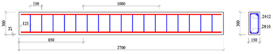
Figure 1.
Details of the test beams.
3.2. Preparation of SFR-CRAC
For the preparation of SFR-CRAC, ordinary silicate cement in a strength grade of 42.5, which was produced by Zhengzhou Tianrui Cement Co. Ltd., China, was used as the binder [16]. The additive was the high-performance polycarboxylic acid water reducer, which produced by Jiangsu Sobute New Materials Co. Ltd., China. The mix water was tap water. Steel fiber was of mill-cut type in length lf = 32 mm and equivalent diameter df = 0.8 mm, and the tensile strength was over 600 MPa, which was produced by Shanghai Harax Steel Fiber Technology Co. Ltd., China.
Due to the great impaction of the morphology of coarse aggregate on the fresh workability and the hardened performances of concrete, the production of recycled aggregate went through a three-stage process [1,3,9,30]. The primary and secondary crushing of demolished concrete blocks and crushed particles were disposed during the first and second stages by a jaw crusher, and the rational particle shape and grading of the recycled aggregate product was performed in the third stage by a vertical impact crusher. The crushers are produced by Zhengzhou Dingsheng Engineering Technology Co. Ltd. China. The coarse aggregate was composited by the recycled coarse aggregate with a particle size of 5–16 mm and the natural aggregate with a particle size of 16–25 mm. To meet the requirement of continuous particle distribution in accordance with the specifications of China codes [31,32], the amount of natural aggregate was 40% in mass of total coarse aggregate based on the optimization of the previous study [16,21,22]. The fine aggregate was the recycled fine aggregate which was the byproduct of recycled coarse aggregate; the gradation with a particle size less than 5 mm met the requirement specified in China code GB/T25176 [33]. The basic properties of aggregates are presented in Table 1, of which the identifier RA is recycled aggregate, and NA is natural aggregate. The water absorption of recycled aggregates at 10 min was over 90% for 24 h.

Table 1.
Basic properties of recycled and natural aggregates.
The mix proportion of SFR-CRAC and referenced CRAC was designed by the absolute volume method on the condition of surface-drying saturated aggregates as per China codes JG/T 472 and JGJ55 [34,35]. The water-to-cement ratio w/c = 0.49 with a kept cement dosage of 409 kg/m3, and the recycled fine aggregate was 42% in mass of total aggregates. For the mix proportion of SFR-CRAC, the mass of steel fibers was counted into the total mass of aggregates, and the dosage of additive was increased with the volume fraction of steel fiber to ensure the rational workability of fresh SFR-CRAC. The additional water was added appropriately based on the tested water absorption of recycled aggregates. After adjustment, the mix proportions were determined as presented in Table 2.
Table 2.
Mix proportion and basic mechanical properties of steel fiber reinforced composite-recycled aggregate concrete (SFR-CRAC) for test beams.
3.3. Fabrication of the Test Beams
The test beams were produced with the following procedure: (1) preparing the raw materials of SFR-CRAC and rebars, (2) fabricating the rebars to be a skeleton, (3) placing the rebar skeleton into the steel mold, (4) casting and compacting the mixture of SFR-CRAC in the steel mold, and (5) demolding and curing.
The single horizontal shaft forced mixer was used to mix the fresh mixture. The aggregates were firstly pre-soaked with the additional water in the mixer for 1 h, then the cement and half dosage of mix water were added and mixed for 30 s. During the mixing, water reducer and another half dosage of mix water were added. After that, the steel fiber was sprinkled into the mixer and mixed for 3 min.
The fresh mixture was cast into the steel mold of the test beams and compacted with vibrators which fixed to the out-sides of the steel mold. After casting and until demolding, the screed top surface was covered by a plastic film for 48 h. After demolding, the test beams were cured with sprayed water for 7 d, then placed in natural condition at least 19 d before testing. As per China standards JG/T472 and GB50152 [30,32], standard specimens of six cubes with dimensions of 150 mm and six prisms with dimensions of 150 mm × 150 mm × 300 mm were made at the same time and cured in the same condition accompanying with each group of the test beams. Three of the cubes as a group were tested for the cubic compressive strength fcu and the splitting tensile strengths fft of SFR-CRAC. Three of the prisms as a group were tested for the axial compressive strength ffc and the modulus of elasticity Ec of SFR-CRAC. Results are presented in Table 2.
3.4. Test Methods
The four-point bending test method was used in this study according to the specification of China standard GB50152 [36]. Two symmetrical concentrated loads were exerted on the top surface of the test beams. The loading device consisting of the steel frame, hydraulic jack, and distributive girder, and the loads were controlled by the load sensors. The mid-span deflection was measured by the electrical displacement meters installed at the mid-span, loading sections, and supports [26,37]. To verify the assumption of plane cross-section, six electrical strain meters were arranged along the depth of the mid-span cross-section. Cracking load was determined through the conditions that the first crack(s) appeared on the side surface of the test beams at the barycenter of longitudinal tensile rebars, and the first point changed slope at the load-deflection curve. Crack width on side surfaces of the test beams at the barycenter of longitudinal tensile rebar was measured by the electrical reading microscope with 0.02 mm precision. The strain of longitudinal tensile rebars was measured by the strain gauges with a length of 1 mm and an electric resistance of 120 Ω. The strain gauges were pasted on each of the longitudinal tensile rebars in space of 268 mm within the pure bending segment, as presented in Figure 2. All the data were collected by a data acquisition system in the lab.
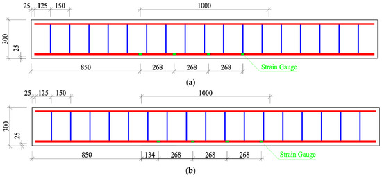
Figure 2.
Arrangement of strain gauges on: (a) one of the longitudinal tensile rebars; (b) another longitudinal tensile rebar.
4. Test Results
4.1. Strain at Mid-Span Cross-Section
Figure 3 presents the concrete strain along the depth of the mid-span section at different bending moment M. With the increase of loads, the sectional neutral axis moved up to reduce the depth of the compressive zone and enlarge the tensile zone of the cross-section. This trend was more obvious on beams with a higher volume fraction of steel fiber such as the test beams RFB-2.0a/b. The concrete strain varied approximately to be linear along the cross-section from top to bottom, which basically satisfied the assumption of plane cross-section [25,27,28,29,30]. This provides the basis of theoretical prediction of the cracking resistance, the tensile stress of longitudinal rebar, and the bearing capacity of the test beams in accordance with the principles of Materials Mechanics.
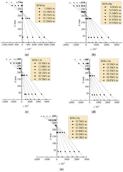
Figure 3.
Concrete strain along depth of the mid-span section: (a) RFB-0a; (b) RFB-0.8a; (c) RFB-1.2a; (d) RFB-1.6a; (e) RFB-2.0a.
4.2. Tensile Strain of Longitudinal Rebars
The average tensile strains of longitudinal rebars at or near the cracked sections within the pure bending segment of each test beam are exhibited in Figure 4. Three parts of the curves are obviously exhibited with the increase of bending moment M. The first linear part started from initial loading to the cracking of concrete. In this part, the rebars have a function to enlarge the geometrical peculiarity of the concrete section to strengthen the cracking resistance of reinforced concrete beams [38]. After that, the tensile strain of the rebar grew fast into the second part until the point of the yield of rebars. The feature point referred to the yield strain εs = fy/Es= 2732με, and different variations appeared between the reinforced SFR-CRAC beams and the reinforced CRAC beams. The strain growth on the reinforced SFR-CRAC beams became slower with the aids of steel fibers bridging cracks, and large nonlinearity appeared with the increase of the vf. This indicated that steel fiber has a function bearing tensile stress in the sectional tensile zone.
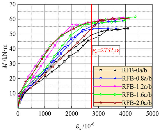
Figure 4.
Changes of the strain of longitudinal tensile rebars with moment on the pure bending sections.
The third part turned up due to the yield of the rebars; the strain quickly grew with small increased loads. This corresponds to the stress–strain relationship of the rebar after yielding. With proper reinforcement ratio, the yield strength of the rebar can be used to compute the bearing capacity of the test beams.
Based on the design principle of the ultimate states for reinforced concrete beams, the crack width and mid-span deflection at normal serviceability should be checked. This corresponds to the loading level M/Mu = 0.45–0.75 considering different combinations of dead loads and live loads on the structures. Here Mu is the ultimate moment at bearing capacity of the cross-section [23,38]. As presented in Figure 5, the tensile strain of the longitudinal rebar increases almost linearly to the loading level in this range. At the same loading level M/Mu, the tensile strain trends to decrease with the increasing vf. Therefore, by using the tensile strength of SFR-CRAC and considering the direct proportionality of stress with strain of the rebar, the predictive formula of the rebar tensile stress σs can be built by modifying that of reinforced concrete beams [23,39], that is:
where M is the moment at normal service stage; as is the distance from the bottom surface of beam to the barycenter of longitudinal tensile rebars, as = cs + d/2 in this test; fft is the tensile strength of SFR-CRAC. fft = 0 for the CRAC.
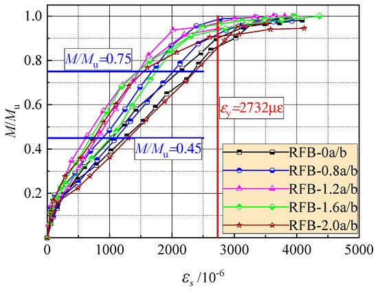
Figure 5.
Strain of the longitudinal tensile rebar at different loading levels.
Table 3 presents the test results of the rebar tensile stress σs at loading level M/Mu = 0.45–0.75. The ratios between tested and calculated values of the σs are exhibited in Figure 6. For the tested reinforced SFR-CRAC beams and the referenced reinforced CRAC beams, the average of the ratios is 0.958 and 1.005, with a dispersion coefficient of 0.098 and 0.103, respectively.
Table 3.
Main tested data of the cracking moment, ultimate moment, and the normal serviceable indices.
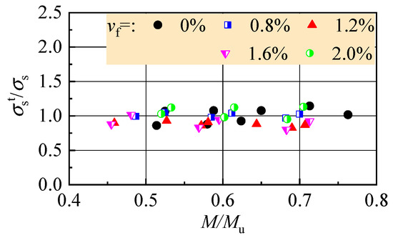
Figure 6.
Ratio of tested to calculated values of the rebar stress at normal service.
4.3. Crack Distribution and Failure Pattern
As exhibited in Figure 7, typical crack distribution appeared within the pure bending segment, and the failure turned up with the yield of longitudinal tensile rebars followed by the crushed SFR-CRAC in the compressive zone, accompanied by the rapid widening of main cracks. Table 3 presents the main tested data of the cracking moment Mcr, the ultimate moment Mu, and the average crack width wm, maximum crack width wmax and mid-span deflection af at normal service stage corresponded to the loading level M/Mu = 0.45−0.75.
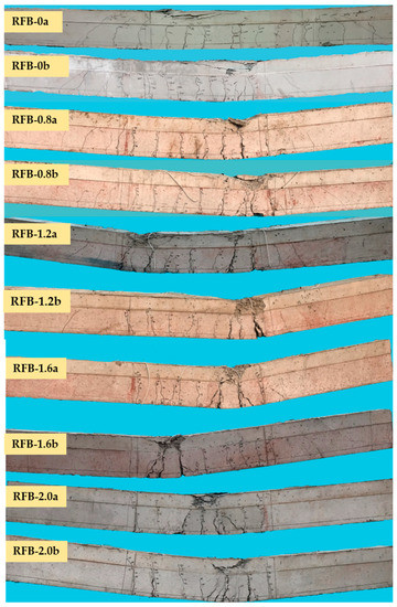
Figure 7.
Crack distribution and failure patterns of the test beams.
The initial crack appeared at a random cross-section, which controlled the cracking resistance of the test beams. Based on test data in Table 3, the moment ratio of cracking to ultimate Mcr/Mu of the test beams increased from 18% to 22% with the increase of the vf from 0% to 2.0%. This indicated a higher enhancement on cracking resistance than bearing capacity by the presence of steel fiber.
New cracks turned up between adjacent cracks until the tensile strain was no longer over the ultimate of SFR-CRAC. After that, the crack spacing became steady, and the main cracks grew in width with the increased bending moment. Due to the random appearance and the different widening of cracks, the variation of crack distribution of reinforced concrete beams at normal serviceability can be described by the average crack spacing and the enlarge coefficient of maximum width from average width [38,39]. Based on test data presented in Table 4, due to more cracks appearing on the pure bending segment, the crack spacing of reinforced SFR-CRAC beams tends to decrease with the increasing vf. By using the crack spacing of conventional reinforced concrete beams as the basis to evaluate the effectiveness of steel fibers, the average crack spacing lfcr of reinforced SFR-CRAC beams can be calculated as:
where ρte is the effective reinforcement ratio of longitudinal tensile rebars; λf is the fiber factor, the product of vf with lf/df of steel fiber.
Table 4.
Test results of crack spacing compared with the calculation at normal serviceability.
With the comparison as presented in Table 4, a good agreement is given out between the tested and the calculated values of crack spacing by the average ratio of 1.046, with a dispersion coefficient of 0.036.
The dispersion of crack width reflects the transferability of tensile stress across cracks, which can be statistically analyzed by the ratios between the width of each crack and the average width of all cracks (wi/wm) on a test beam [39,40]. Considering the main cracks on the reinforced SFR-CRAC beams, the frequency of the ratios is counted as exhibited in Figure 8. Sixty-one main cracks appeared on the test beams with 186 test data of crack width. After analysis, the frequency histogram of wi/wm fits the normal distribution. Taking the assurance rate at 95%, the enlarging coefficient of maximum width from average width τs = 0.991 + 1.645 × 0.376 = 1.61. This is slightly small compared with that τs = 1.66 for the conventional reinforced concrete beams [38]. The reduction of the enlarging coefficient means a uniform distribution of crack width on the reinforced SFR-CRAC beams.
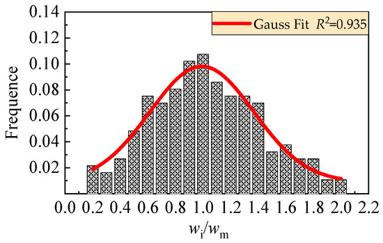
Figure 8.
Statistical analysis of distribution of crack width.
It can be seen from Table 3 that the maximum crack width was up to 0.34 mm for reinforced CRAC beams, while the tensile stress of longitudinal rebar was 46.4–83.8% of yield strength. The presence of steel fibers could reduce the crack width lower than 0.25 mm with the tensile stress of longitudinal rebars at 34.4–77.9% yield strength. This indicates the reinforced SFR-CRAC beams can satisfy a stricter limit of crack width to meet the durability of concrete structures [41]. Meanwhile, due to the increase of the ultimate moment at bearing capacity, the reinforced SFR-CRAC beams have higher loading capacity at normal serviceability. For example, compared with beams RFB-0a/b, beams RFB-2.0a/b had a 16.4% increment of the ultimate moment, with the equal increment the moment at normal serviceability can be increased by 16.4%. This benefits to the improvement of the normal loading capacity of reinforced SFR-CRAC beams on conditions satisfying both of normal serviceability and ultimate bearing capacity.
4.4. Mid-span Deflection and Flexural Ductility
As presented in Figure 9, four segments can be seen from the curves of mid-span deflection changing with the moment. The first is linear with elastic deformation of SFR-CRAC before cracking. The second is almost linear with the crack development; this belongs to the normal serviceability of the test beams. The third turns up with obvious nonlinearity due to the plastic compression and the rapid development of cracks followed with the yield of longitudinal tensile rebars. This presents to the ultimate state of bearing capacity of the test beams. The fourth exhibits the residual loading capacity with large plastic deformation after yield of longitudinal tensile rebars; the gentle slope and greater deflection reflect the beneficial effect of steel fiber on the flexural ductility, and the mid-span deflection of the test beams at failure state increases with the vf.
Figure 9.
Mid-span deflection changed with moment of the test beams.
The flexural ductility of reinforced concrete beams is always defined as the ratio of deflection δi at a post-peak moment to that δy corresponding to the yield of longitudinal tensile rebar. Of which, δ0.85, δ0.95, and δ1.0 were normally taken as the deflection at the post-peak moment of 0.85Mu, 0.95Mu, and Mu [26,42]. The flexural ductility index βi is computed as follows:
The results are presented in Table 5 and Figure 10. In spite of the dispersion of test data, nonlinear increasing of βi exists with the increase of vf no matter what level of the post-peak moment is adopted. The slight decrease of β1.0 indicates the increase of flexural stiffness at peak moment due to the enhancement of steel fiber bridging the cracks in the tensile zone. Compared to the reinforced CRAC beams, the flexural ductility indexes β0.85 and β0.95 of reinforced SFR-CRAC beams with vf = 2.0% increased by about 204% and 154% on average. The promotion of β0.85 over β0.95 implies the flexural ductility at the post-peak moment was improved significantly by the presence of steel fibers with larger vf. Moreover, the increase of flexural ductility index β0.85 with vf demonstrates the promotion of the post-peak loading sustainability of reinforced SFR-CRAC beams due to the benefits of steel fibers bridging the cracks and keeping the entirety of compression zone.
Table 5.
Calculation results of flexural ductility index of the test beams.
Figure 10.
Flexural ductility indexes of the test beams with a varying vf.
5. Discussion
5.1. Cracking Resistance
The cracking resistance of reinforced SFR-CRAC trends to increase with the vf. As presented in Figure 11, almost the same increments of cracking moment Mfcr and tensile strength fft are produced with similar growth rates of 0.19 and 0.18. This indicates the effect of steel fiber on the cracking resistance of reinforced SFR-CRAC beams depends on the enhancement of tensile strength of SFR-CRAC, and the increment of Mfcr of reinforced SFR-CRAC beams can be predicted by the increment of fft with the same vf.
Figure 11.
Comparison of the changes with vf: (a) Mfcr; (b) fft.
Based on the principle of Materials Mechanics, and considering the beneficial effect of subsistent plasticity of SFR-CRAC in the tensile zone of the cross-section, the Mfcr of reinforced SFR-CRAC beam can be predicted by the following formulas [26,38,39]:
where γ is the sectional plasticity coefficient of resistance-moment; W0 is the elastic resistance-moment to the tensile edge of transformed section.
where I0 is the inertia moment of transformed section to its centroid; y0 is the distance of centroid to compressive edge of transformed section; αE is the ratio of the modulus of elasticity of the rebar to that of SFR-CRAC; As is the sectional area of longitudinal tensile rebars.
By using Formula (5), the ratio of test value to the calculated value of Mfcr changes from 0.992 to 1.132, and the mean ratio is 1.046, with a dispersion coefficient of 0.036. A good agreement between tested and calculated values are presented in Figure 12.
Figure 12.
Test and calculated cracking moment of reinforced SFR-CRAC beams.
5.2. Crack Width
Combined with the bond-slip model of cracks on the reinforced concrete beams, steel fibers in the tensile zone improve the transferability of tensile stress of concrete across cracks, and assist the tensile rebars to confine the opening of cracks. Therefore, except for the improvement of crack distribution by shortening the crack spacing lfcr and reducing the enlarging coefficient τs of maximum crack width wmax from average crack width wm, steel fibers also adjust the uneven strain distributions of SFR-CRAC and longitudinal tensile rebar among cracks. The coefficient αc reflecting the uneven deformation of SFR-CRAC between cracks becomes bigger, and the coefficient ψ reflecting the uneven strain distribution of longitudinal tensile rebar among cracks becomes smaller. The predictive formulas for the maximum and average crack width on the side surface of reinforced SFR-CRAC beams at the barycenter of longitudinal tensile rebars can be written as follows [37,38,39]:
Based on test data of this study, αc = 0.85 for referenced reinforced CRAC beams, and αc = 0.95 for reinforced SFR-CRAC beams. The larger αc means the smaller uneven deformation of SFR-CRAC between cracks. The ratios between tested values in Table 3 and calculated values with Formula (11) of the average crack width, and Formula (10) of the maximum crack width are exhibited in Figure 13. For the referenced reinforced CRAC beams, the averaged ratios of the average crack width and the maximum crack width are 1.045 and 1.059, with a dispersion coefficient of 0.180 and 0.111, respectively. For the reinforced SFR-CRAC beams, the averaged ratios of the average crack width and the maximum crack width are 1.027 and 0.967, with a dispersion coefficient of 0.173 and 0.176, respectively.
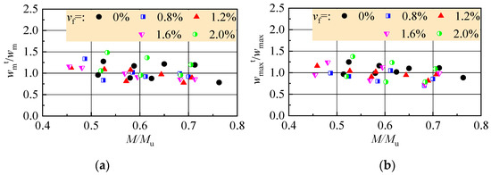
Figure 13.
Ratio of tested to calculated values: (a) average crack width; (b) maximum crack width.
5.3. Flexural Stiffness
Based on the principle of Materials Mechanics, the mid-span deflections of the reinforced SFR0CRAC beams can be computed as:
where Bs is the equivalent flexural stiffness of beam.
Figure 14 presents the tested Bst computed with aft in Table 3. Corresponding to the changes of aft, Bst decreased with the increase of load level M/Mu, and had an uptrend with vf.
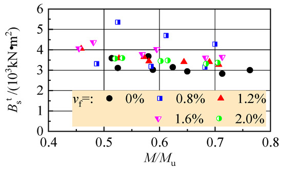
Figure 14.
Tested flexural stiffness changed with moment of the test beams.
Referring to that of steel fiber reinforced expanded-shale lightweight concrete beams [26], the equivalent flexural stiffness of reinforced SFR-CRAC beams at mid-span can be calculated as:
where αB is the coefficient reflecting the initial damages on the elastic flexural stiffness.
Based on test data of this study, αB = 0.85 for referenced reinforced CRAC beams, and αB = 0.95 for reinforced SFR-CRAC beams. This indicates the smaller initial damages of reinforced SFR-CRAC beams. The ratios of tested to calculated flexural stiffness Bst/Bs are displayed in Figure 15. For the referenced reinforced CRAC beams, the ratios change from 1.030 to 1.294, and the mean value is 1.112, with a dispersion coefficient of 0.084. For reinforced SFR-CRAC beams, the ratios change from 0.924 to 1.553, and the mean value is 1.085, with a dispersion coefficient of 0.144.
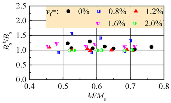
Figure 15.
Test to calculation ratios of flexural stiffness.
5.4. Flexural Capacity
Considering the beneficial effect of steel fibers in tensile zone of cross-section, and on the promise of keeping the numerical diagram of moment capacity for conventional reinforced concrete beams, as seen in Figure 16, the strengthening effect of steel fibers in tensile zone is simplified as an equivalent rectangular with the effective stress fftu at a depth of xt [25,26,27]. Based on the principle of force and moment equilibrium at the cross-section, the ultimate moment Mfu of reinforced SFR-CRAC beams can be calculated with the formulas as follows:
where ft is the tensile strength of CRAC with the same strength grade of SFR-CRAC; x is the compression depth of equivalent rectangular stress block; α1 is a coefficient of equivalent rectangular stress; β1 is a coefficient about the depth of equivalent rectangular. In this study, α1 = 1.0 and β1 = 0.75 for the strength fcu < 40 MPa [23,38].
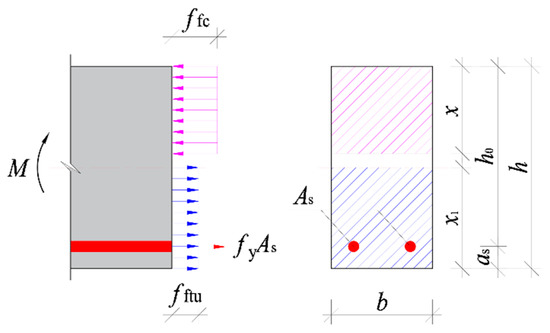
Figure 16.
Numerical diagram of the ultimate moment at the cross-section.
Combined with the test data, and resolve the formulas to get the x, and then βtu could be got. Take the mean value of βtu = 1.15. The comparison of tested and calculated values of Mfu is presented in Figure 17. A good agreement is given out with the mean ratio of tested to calculated values of 0.986, with a dispersion coefficient of 0.034.
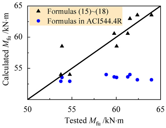
Figure 17.
Tested and calculated ultimate moment of reinforced SFR-CRAC beams.
The test data is also verified by the calculation model of ACI544.4R considering the enhancement of steel fiber in the tensile zone of the beams [28]. As presented in Figure 17, a mean ratio of tested to calculated values is 1.104, with a dispersion coefficient of 0.061. It shows that the calculated moment was obviously lower than the test value.
6. Conclusions
Based on the study of this paper, the conclusions can be drawn as follows:
- (1)
- Steel fiber reinforced composite-recycled aggregate concrete (SFR-CRAC) prepared in this study has good workability to produce the reinforced SFR-CRAC beams.
- (2)
- Similar to conventional reinforced concrete beams, the assumption of plane cross-section is valid to build the calculation models of cracking resistance, crack width, flexural stiffness, and flexural capacity of the reinforced SFR-CRAC beams.
- (3)
- The same enhancement of steel fibers on the cracking resistance of reinforced SFR-CRAC beams and the tensile strength of SFR-CRAC. The cracking moment of reinforced SFR-CRAC beams can be predicted by using the tensile strength of SFR-CRAC. The reduced crack spacing and good crack distribution pattern of reinforced SFR-CRAC benefit to minimize the crack width. This also improves the strain distribution pattern and reduces the tensile stress of longitudinal tensile rebars at cracked sections. Therefore, the 500 MPa longitudinal tensile rebars work at a high stress level with the premise of matching the limit crack width specified in the standard for reinforced SFR-CRAC beams at normal serviceability state. The flexural stiffness of reinforced SFR-CRAC beams at normal serviceability also increased with the improvement of crack distribution.
- (4)
- Designed with the rational longitudinal reinforcement ratio, the reinforced SFR-CRAC beams fail in the typical mode of the yield of 500 MPa longitudinal rebars followed by the fast widening of main cracks and the crushed SFR-CRAC in the compression zone. Good flexural ductility presents on the reinforced SFR-CRAC beams matched with 500 MPa longitudinal rebars, especially at the post-peak loading levels.
- (5)
- Considering the improvements by steel fibers and linked with those of conventional reinforced concrete beams, formulas for predicting the cracking moment, crack width, flexural stiffness, and ultimate moment of SFR-CRAC beams are proposed for the reference of design.
Author Contributions
Methodology, F.L. and X.L.; tests, data interpretation and writing—original draft, S.P., K.F., H.G., and X.L.; writing—review and funding acquisition, F.L. All authors have read and agreed to the published version of the manuscript.
Funding
This study was funded by Key Scientific and Technological Research Project of University in Henan, China (grant number 18A560013 and 16A560023), and Innovative Sci-Tech Team of Eco-Building Material and Structural Engineering of Henan Province, China (grant number YKRZ-6-066).
Acknowledgments
The authors thanks to the supervision of Shunbo Zhao as a leader of the research team.
Conflicts of Interest
The authors declare no conflicts of interest.
References
- Lotfi, S.; Eggimann, M.; Wagner, E.; Mróz, R.; Deja, J. Performance of recycled aggregate concrete based on a new concrete recycling technology. Constr. Build. Mater. 2015, 95, 243–256. [Google Scholar] [CrossRef]
- Liang, Y.-C.; Ye, Z.-M.; Vernerey, F.; Xi, Y. Development of Processing Methods to Improve Strength of Concrete with 100% Recycled Coarse Aggregate. J. Mater. Civ. Eng. 2015, 27, 04014163. [Google Scholar] [CrossRef]
- Katz, A. Treatments for the Improvement of Recycled Aggregate. J. Mater. Civ. Eng. 2004, 16, 597–603. [Google Scholar] [CrossRef]
- Qiu, J.; Tng, D.Q.S.; Yang, E. Surface treatment of recycled concrete aggregates through microbial carbonate precipitation. Constr. Build. Mater. 2014, 57, 144–150. [Google Scholar] [CrossRef]
- Elhakam, A.A.; Mohamed, A.E.; Awad, E. Influence of self-healing, mixing method and adding silica fume on mechanical properties of recycled aggregates concrete. Constr. Build. Mater. 2012, 35, 421–427. [Google Scholar] [CrossRef]
- Butler, L.; West, J.S.; Tighe, S.L. Effect of recycled concrete coarse aggregate from multiple sources on the hardened properties of concrete with equivalent compressive strength. Constr. Build. Mater. 2013, 47, 1292–1301. [Google Scholar] [CrossRef]
- Zhao, S.; Guo, Q.; Li, G.X.; Su, Y.F. Basic Mechanical Properties of Concrete with Machine-Made Sand and Recycled Coarse Aggregate. Appl. Mech. Mater. 2013, 357, 1102–1105. [Google Scholar] [CrossRef]
- Corinaldesi, V.; Moriconi, G. Influence of mineral additions on the performance of 100% recycled aggregate concrete. Constr. Build. Mater. 2009, 23, 2869–2876. [Google Scholar] [CrossRef]
- Ostrowski, K.; Stefaniuk, D.; Sadowski, Ł.; Krzywiński, K.; Gicala, M.; Różańska, M. Potential use of granite waste sourced from rock processing for the application as coarse aggregate in high-performance self-compacting concrete. Constr. Build. Mater. 2020, 238, 117794. [Google Scholar] [CrossRef]
- Brand, A.S.; Roesler, J.R.; Salas, A. Initial moisture and mixing effects on higher quality recycled coarse aggregate concrete. Constr. Build. Mater. 2012, 79, 565–573. [Google Scholar] [CrossRef]
- Wijayasundara, M.; Mendis, P.; Crawford, R.H. Integrated assessment of the use of recycled concrete aggregate replacing natural aggregate in structural concrete. J. Clean. Prod. 2017, 174, 591–604. [Google Scholar] [CrossRef]
- Li, C.Y.; Nie, P.; Li, F.L. Study on mechanical properties and water permeability of recycled aggregate porous concrete. Adv. Mater. Res. 2012, 366, 36–39. [Google Scholar] [CrossRef]
- Li, F.L.; Li, J.; Chen, S.; Zhao, W.J. Experiment of basic mechanical properties of concrete mixed with composite aggregate. Adv. Mater. Res. 2011, 168–170, 2178–2181. [Google Scholar] [CrossRef]
- Ding, X.X.; Li, C.Y.; Xu, Y.Y.; Li, F.L.; Zhao, S.B. Experimental study on long-term compressive strength development of concrete with manufactured sand. Constr. Build. Mater. 2016, 108, 67–73. [Google Scholar] [CrossRef]
- Zhao, S.; Ding, X.; Zhao, M.; Li, C.; Pei, S. Experimental study on tensile strength development of concrete with manufactured sand. Constr. Build. Mater. 2017, 138, 247–253. [Google Scholar] [CrossRef]
- Li, C.Y.; Wang, F.; Deng, X.S.; Li, Y.Z.; Zhao, S.B. Experimental study on strength development of recycled-aggregate concrete with large particle natural aggregate. Materials 2019, 12, 1891. [Google Scholar] [CrossRef]
- Zhao, M.L.; Ding, X.X.; Li, J.; Law, D. Numerical Analysis of Mix Proportion of Self-Compacting Concrete Compared to Ordinary Concrete. Key Eng. Mater. 2018, 789, 69–75. [Google Scholar] [CrossRef]
- Ding, X.X.; Zhao, M.L.; Zhou, S.Y.; Fu, Y.; Li, C.Y. Statistical analysis and preliminary study on the mix proportion design of self-compacting steel fiber reinforced concrete. Materials 2019, 12, 637. [Google Scholar] [CrossRef]
- Ding, X.X.; Li, C.Y.; Han, B.; Lu, Y.Z.; Zhao, S.B. Effects of different deformed steel-fibers on preparation and fundamental properties of self-compacting SFRC. Constr. Build. Mater. 2018, 168, 471–481. [Google Scholar] [CrossRef]
- Li, C.Y.; Shang, P.R.; Li, F.L.; Feng, M.; Zhao, S.B. Shrinkage and mechanical properties of self-compacting SFRC with calcium sulfoaluminate expansive agent. Materials 2020, 13, 588. [Google Scholar] [CrossRef]
- Li, C.Y.; Geng, H.B.; Deng, C.H.; Li, B.C.; Zhao, S.B. Experimental investigation on columns of steel fiber reinforced concrete with recycled aggregates under large eccentric compression load. Materials 2019, 3, 445. [Google Scholar] [CrossRef] [PubMed]
- Cheng, D.D.; Geng, H.B.; Li, Q.; Li, B.C.; Ma, K. Study on large eccentric compression resistance of steel fiber recycled concrete columns. Hans J. Civ. Eng. 2018, 3, 313–320. [Google Scholar] [CrossRef]
- Ministry of Housing and Urban-Rural Construction of the People’s Republic of China. Code for Design of Concrete Structures; China Building Industry Press: Beijing, China, 2010; GB50010-2010. (In Chinese) [Google Scholar]
- Xu, J.J.; Chen, Z.P.; Xue, J.Y.; Chen, Y.L.; Liu, Z.Q. A review of experimental results of steel reinforced recycled aggregate concrete members and structures in China (2010–2016). Procedia Eng. 2017, 210, 109–119. [Google Scholar] [CrossRef]
- Li, C.Y.; Zhao, S.B.; Chen, H.; Gao, D.Y. Experimental study on flexural capacity of reinforced SFRFLC superposed beams. J. Build. Struct. 2015, 2, 257–264. [Google Scholar]
- Zhao, M.S.; Su, J.Z.; Shang, P.R.; Zhao, S.B. Experimental study and theoretical prediction of flexural behaviors of reinforced SFRELC beams. Constr. Build. Mater. 2019, 208, 454–463. [Google Scholar] [CrossRef]
- China Association for Engineering Construction Standardization. Technical Specification for Steel Fiber Reinforced Concrete Structures; China Plan Press: Beijing, China, 2004; CECS38:2004. (In Chinese) [Google Scholar]
- ACI Committee 544. Design Considerations for Steel Fiber Reinforced Concrete; American Concrete Institute: Farmington Hill, MI, USA, 2009; ACI 544.4R-2009. [Google Scholar]
- Ministry of Housing and Urban-Rural Construction of the People’s Republic of China. Design Standard for Steel Fiber Reinforced Concrete Structures; China Standard Press: Beijing, China, 2020; JGJ/T465-2019. [Google Scholar]
- Ostrowski, K.; Sadowski, Ł.; Stefaniuk, D.; Wałach, D.; Gawenda, T.; Oleksik, K.; Usydus, I. The Effect of the Morphology of Coarse Aggregate on the Properties of Self-Compacting High-Performance Fibre-Reinforced Concrete. Materials 2018, 11, 1372. [Google Scholar] [CrossRef]
- Ministry of Housing and Urban-Rural Construction of the People’s Republic of China. Standard for Technical Requirements and Test Method of Sand and Crushed Stone (or Gravel) for Ordinary Concrete; China Building Industry Press: Beijing, China, 2006; JGJ 52-2006.
- Ministry of Housing and Urban-Rural Construction of the People’s Republic of China. Recycled Coarse Aggregate for Concrete; Standard Press of China: Beijing, China, 2011; GB/T 25177-2010.
- Ministry of Housing and Urban-Rural Construction of the People’s Republic of China. Recycled Fine Aggregate for Concrete and Mortar; Standard Press of China: Beijing, China, 2011; GB/T 25176-2010.
- Ministry of Housing and Urban-Rural Construction of the People’s Republic of China. Steel Fiber Reinforced Concrete; China Standard Press: Beijing, China, 2015; JG/T472-2015.
- Ministry of Housing and Urban-Rural Construction of the People’s Republic of China. Specification for Mix Proportion Design of Ordinary Concrete; China Building Industry Press: Beijing, China, 2011; JGJ 55-2011.
- Ministry of Housing and Urban-Rural Construction of the People’s Republic of China. Standard of Test Methods of Concrete Structures; China Building Industry Press: Beijing, China, 2012; GB/T50152-2012.
- Li, X.K.; Li, C.Y.; Zhao, M.L.; Yang, H.; Zhou, S.Y. Testing and prediction of shear performance for steel fiber reinforced expanded-shale lightweight concrete beams without web reinforcements. Materials 2019, 12, 1594. [Google Scholar] [CrossRef]
- Zhao, S.B. Design Principle of Concrete Structures, 2nd ed.; Tongji University Press: Shanghai, China, 2013. [Google Scholar]
- Zhao, S.B.; Guan, J.F.; Li, X.K. Simulation Testing and Optimal Design of Reinforced Concrete Structures; China Water Power Press: Beijing, China, 2011. [Google Scholar]
- Zhao, S.B.; Guan, J.F.; Zhang, X.P.; Cheng, X.T. Experimental study and statistical analysis of crack patterns of reinforced concrete beams. Eng. Mech. 2008, 12, 141–146. [Google Scholar]
- Ministry of Housing and Urban-Rural Construction of the People’s Republic of China. Code for Durability Design of Concrete Structures; China Building Industry Press: Beijing, China, 2008; GB50476-2008.
- European Committee for Standardization. Design of Structures for Earthquake Resistance; Part 1: General Rules, Seismic Actions and Rules for Buildings; European Committee for Standardization: Brussels, Belgium, 2004; Eurocode 8. EN 1998-1. [Google Scholar]


© 2020 by the authors. Licensee MDPI, Basel, Switzerland. This article is an open access article distributed under the terms and conditions of the Creative Commons Attribution (CC BY) license (http://creativecommons.org/licenses/by/4.0/).