Abstract
This paper presents, for the first time, the mechanical model and theoretical analysis of free vibration of a spinning functionally graded graphene nanoplatelets reinforced composite (FG-GPLRC) porous double-bladed disk system. The nanocomposite rotor is made of porous metal matrix and graphene nanoplatelet (GPL) reinforcement material with different porosity and nanofillers distributions. The effective material properties of the system are graded in a layer-wise manner along the thickness directions of the blade and disk. Considering the gyroscopic effect, the coupled model of the double-bladed disk system is established based on Euler–Bernoulli beam theory for the blade and Kirchhoff’s plate theory for the disk. The governing equations of motion are derived by employing the Lagrange’s equation and then solved by employing the substructure mode synthesis method and the assumed modes method. A comprehensive parametric analysis is conducted to examine the effects of the distribution pattern, weight fraction, length-to-thickness ratio, and length-to-width ratio of graphene nanoplatelets, porosity distribution pattern, porosity coefficient, spinning speed, blade length, and disk inner radius on the free vibration characteristics of the FG-GPLRC double-bladed disk system.
1. Introduction
Spinning bladed disk rotor systems are the core components in many rotary machines in helicopter rotor, ship power propulsion system, engineering agitator, and so on [1,2,3,4,5,6]. By adopting the finite element method, Ma et al. [7] studied the vibration characteristics of bladed disk structure subject to rubbing force at the blade tip. Battiato et al. [8] experimentally investigated the vibration response of the spinning bladed disk system. Bai et al. [9] employed an extremum response surface method-based improved substructural component modal synthesis to study the vibration behavior of a mistuned bladed disk structure. These previous studies showed that a continuous increase in the spinning speed frequently leads to excessive vibration of the system.
It has been well accepted that the use of advanced materials is one of the effective ways to improve the mechanical performance of the bladed disk rotor system to avoid undesired vibration. Owing to its superior mechanical properties, graphene and its derivatives such as graphene nanoplatelets have attracted huge attention from both research and industry communities with numerous efforts on the applications of graphene-based nanomaterials in different fields. Rafiee et al. [10] experimentally found that GPLs have distinct advantages as reinforcing nanofillers over carbon nanotubes at a very low content, which has also been theoretically confirmed [11,12,13,14]. Compared with single-layer graphene, GPLs has comparable elastic modulus, less agglomeration, better dispersion, and much lower cost; hence, they have been widely used in many high-performance composite structures with greatly enhanced structural stiffness. Feng et al. [15] investigated the nonlinear free vibration of GPL reinforced beams. By using the finite element method, Tam et al. [16] and Zhao et al. [17] studied the vibration characteristics of GPL-reinforced beams, with a particular focus on the effects of open edge cracks and trapezoidal plates, respectively. Guo et al. [18] presented a theoretical study on the nonlinear bending of GPL-reinforced plates by employing the element-free IMLS-Ritz method. Wu et al. [19] and Song et al. [20] investigated the vibration behavior of FG annular plates and cracked beams reinforced by GPLs in thermal environments. The in-plane and out-of-plane free vibration performance of an FG-GPLRC arch was discussed by Yang et al. [21].
Due to its light weight and low density, porous metal foam is one of the most promising advanced engineering materials [22,23,24]. Based on the sinusoidal shear deformation theory, Wang et al. [25] investigated free vibrations of FG porous cylindrical shells. Ebrahimi et al. [26] studied the nonlinear vibration of FG porous Timoshenko beams. Wang et al. [27] conducted the vibration analysis of FG porous plates in thermal environments. Both the classical and first-order shear deformation plate theories are used by Kim et al. [28] to study the vibration behavior of FG porous microplates. Recent studies [29,30] also showed that incorporating GPLs into FG porous structures is another avenue for the development of advanced composite structures that are lightweight yet very strong.
It should be noted that all of the existing research works available in the open literature are for a single FG-GPLRC beam, plate, or shell only; no research work has been conducted on the mechanical performance of an FG-GPLRC assembly consisting of two or more structural elements. This paper makes the first attempt to model and analyze the free vibration of a spinning FG porous double-bladed disk system reinforced with GPLs. Based on Euler–Bernoulli beam theory and Kirchhoff’s plate theory, the equations of motion governing the coupled vibration are derived by employing Lagrange’s equation. Then, the substructure mode synthesis method and the assumed modes method are adopted to solve the equations of motion. Special attention is given to the effects of the spinning speed, GPL distribution pattern, GPL weight fraction, length-to-thickness ratio and length-to-width ratio of GPLs, porosity distribution pattern, porosity coefficient, blade length, and disk inner radius on the free vibration of the rotor. The obtained results are of practical significance for the design of FG-GPLRC porous double-bladed disk systems.
2. Theoretical Formulations
2.1. Modeling
The theoretical model of a double-bladed disk system is shown in Figure 1. The two same blades are connected at Qk (k = 1, 2) on the outer edge of the disk in opposite directions with the inner edge of the disk clamped. As can be seen, the inner radius, outer radius, and thickness of the disk are a, b and hD, respectively; the length, width, and thickness of the blades are LB, WB, and hB, respectively.
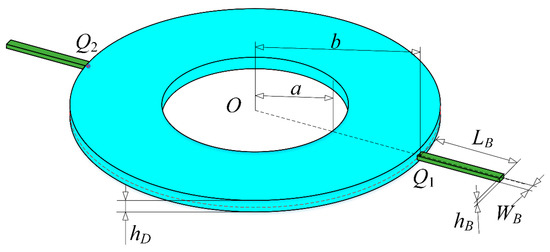
Figure 1.
A spinning double-bladed disk system.
To describe the motion and deformation of the coupled rotor, four different coordinate systems as shown in Figure 2 are defined, where O-xyz is the global system fixed at O; O0-x0rθ is a cylindrical coordinate system spinning at Ω along the x0-axis; O1-x1y1z1 is a rectangular coordinate system spinning at Ω along the x1-axis; O2-x2y2z2 is a rectangular coordinate system fixed at Qk spanned by a deflection angle along the y1-axis with respect to O1-x1y1z1.
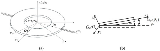
Figure 2.
Coordinate systems: (a) for the disk, (b) for the kth blade.
2.2. Material Properties
The double-bladed disk system is made of a porous metal matrix and GPL reinforcement. Three porosity distribution patterns are considered as shown in Figure 3 for the disk (XPD, UPD, OPD) and two blades (XPB, UPB, OPB). According to the open-cell scheme [31], the specific expressions of material properties are determined by:
where subscripts D and B stand for the disk and blades, respectively; ED(B), ρD(B), and μD(B) are the effective Young’s modulus, mass density, and Poisson’s ratio, respectively; ED0(B0), ρD0(B0), and μD0(B0) are the Young’s modulus, mass density, and Poisson’s ratio of the GPL-reinforced material without pores, respectively; eD0(B0), e*D0(B0), and αD(B) are the porosity coefficients with respect to the three porosity distributions, respectively; eDm(Bm), e*Dm(Bm), and α′D(B) are the mass density coefficients with respect to the three porosity distributions, respectively.
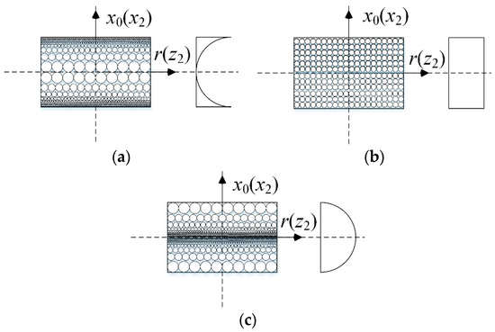
Figure 3.
Porosity distribution patterns in the disk and blades: (a) Pattern XPD (XPB), (b) Pattern UPD (UPB), (c) Pattern OPD (OPB).
Applying the typical mechanical property relationship
gives the relations of the porosity coefficients and mass density coefficients:
Due to the equal mass in different distributions, it can be obtained as:
Thus, the porosity and mass density coefficients can be given as listed in Table 1.

Table 1.
Variation of porosity coefficients.
Moreover, according to the modified Halpin–Tsai model [32], ED0(B0) can be expressed as:
in which EGPL and EM are the Young’s modulus of GPLs and the matrix, respectively. The geometry factors ξlD(lB) and ξwD(wB) of GPLs in the disk and blades are given as:
where lD(B), wD(B), and tD(B) are the GPL’s average length, width, and thickness in the disk and blades, respectively.
Based on the rule of mixture, ρD0(B0) and μD0(B0) are:
in which ρGPL and ρM are the Young’s modulus of GPLs and the matrix, respectively; μGPL and μM are the Poisson’s ratio of the GPLs and the matrix, respectively.
Since the manufacturing of an ideal FG-GPLRC with a smooth change in material composition is impossible due to the limitation of current manufacturing technology, a multilayer structure with both GPL and porosity distributions varying from layer to layer is adopted to achieve an approximate gradient. Each layer has the same thickness and evenly distributed pores and GPLs. As shown in Figure 4, the layer numbers of the disk and blades are ND and NB, respectively.
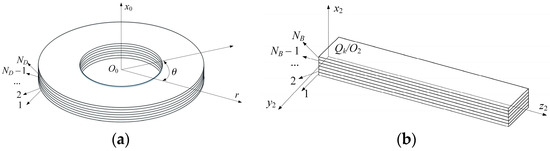
Figure 4.
Nanocomposite structures: (a) for the disk, (b) for the kth blade.
Three GPL distributions shown in Figure 5 are considered in the present study. It can be found that Pattern X provides the maximum GPL volume fraction around the surfaces of the disk and blades, while Pattern O gives the minimum one. Meanwhile, Pattern U is the uniform distribution of GPLs.
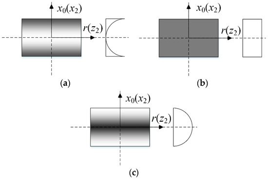
Figure 5.
Graphene nanoplatelet (GPL) distribution patterns in the disk and blades: (a) Pattern XGD (XGB), (b) Pattern UGD (UGB), and (c) Pattern OGD (OGB).
For different GPL distributions, the GPL volume fraction can be written as:
where q = 1, 2, and 3 are corresponding to the porosity pattern XPD(PB), UPD(PB), and OPD(PB); sq1D(q1B), sq2D(q2B), and sq3D(q3B) are the coefficients of GPL volume fraction in the disk and blades, which can be calculated from:
in which:
The total GPL volume fraction VTGPLD(GPLB) is determined by:
where WGPLD(GPLB) is the GPL weight fraction.
2.3. Energy Functions
The energy method is adopted to obtain the equations of motion. Thus, the kinetic energy and potential energy need to be given in the first place.
The velocity of an arbitrary point in the disk is:
Thus, the kinetic energy of the disk can be obtained as:
Considering the gyroscopic effect, on the basis of Kirchhoff’s plate theory, the total potential energy of the disk is:
in which:
where:
Similarly, the velocity of an arbitrary point in the kth blade (k = 1, 2) is:
in which:
Therefore, the kinetic energy of the kth blade can be derived as:
The total kinetic energy of the blades is:
According to Euler–Bernoulli beam theory, the strain of the kth blade is:
The deformation potential energy of the kth blade can be written as:
The centrifugal force of the kth blade is:
Thus, the centrifugal potential energy of the kth blade is
Finally, the total potential energy of the blades is:
2.4. Equations of Motion
The motion of each structure component in the double-bladed disk system is approximated by the weighted superposition of admissible functions. The displacements of the disk can be expressed as
in which QD(t) and ΦD(r) are the generalized coordinate vector and mode function vector of the disk, respectively:
where M is the total mode number of the disk; the specific mode function Rj(r) is:
in which J1 and N1 are Bessel functions of the first kind and second kind; I1 and K1 are modified Bessel functions of the first kind and second kind; Aj, Bj, Cj, Dj and βj are the coefficients determined by the boundary conditions of the disk, respectively.
In addition, the displacements of the kth blade are:J
where (QUk, QVk) and (ΦUk, ΦVk) are the generalized coordinate vector and mode function vector of the kth blade, respectively. Their specific expressions are:
in which Nk and Pk are the total mode numbers of the kth blade along the x3-axis direction (uB) and y3-axis direction (vB); the specific mode function Ykj(z3) is:
and αkj can be calculated from:
Substituting the energy expressions in Section 2.3 into the Lagrange equation
gives the governing equations of coupled motion of the FG-GPLRC blade–disk system:
where
The specific expressions of each element in the mass matrix M, gyroscopic matrix G, and stiffness matrix K are given in Appendix A.
Due to the gyroscopic matrix G caused by rotation, the coupled governing equations cannot be solved directly by the eigenvalue method. For free vibration analysis, Equation (37) needs to be converted into the state form by introducing:
in which the state vector p(t) and state matrix B can be determined by:
where E is the unity matrix.
Setting
and substituting Equation (43) into Equation (41) yields:
where i = (−1)0.5.
Thus, the natural frequencies ω of the blade–disk system can be obtained by solving the eigenvalue problem.
In addition, the backward travelling wave frequency ωb and forward travelling wave frequency ωf can be obtained as:
3. Results and Discussion
In this section, the free vibration behavior of the spinning FG-GPLRC porous double-bladed disk system is studied comprehensively. Unless otherwise stated, the structural parameters are a = 0.4 m, b = 0.8 m, hD = 0.03m, lB = 0.4 m, W = 0.02 m and hB = 0.01 m; the material parameters are EGPL = 1010 GPa, EM = 130 GPa, ρGPL = 1062.5 kg/m3, ρM = 8960 kg/m3, μGPL = 0.186, μM = 0.34, WGPLD = WGPLB = 1%, LD/tD = LB/tB = 100 and LD/BD = LB/BB = 2, e0D = e0B = 0.1. Moreover, the porosity distributions pattern XPD, XPB and GPL distribution patterns XGD and XGB are considered in the following analysis.
3.1. Convergence and Comparison Study
Before parametric analysis, the convergence regarding the vibration mode number and GPL layer number used in the analysis is investigated firstly. As displayed in Table 2 and Table 3, convergent results for the first three frequencies can be achieved at (M = 5, N1 = N2 = 16, P1 = P2 = 13) and (ND = NB = 16), which will be adopted in the following calculations.
Table 2.
Frequencies ω (rad/s) of the functionally graded graphene nanoplatelets reinforced composite (FG-GPLRC) porous double-bladed disk system with different mode numbers (Ω = 0 rad/s).
Table 3.
Frequencies ω (rad/s) of the FG-GPLRC porous double-bladed disk system with different layer numbers (Ω = 0 rad/s).
Since there are no suitable data in the open literatures for direct comparison, the finite element method using commercial software ABAQUS is employed to further verify the present modeling and vibration analysis. Table 4 and Figure 6 show the comparison of frequencies and vibration modes between theoretical (MATLAB) and FE (ABAQUS) results with different spinning speeds, respectively. Here, GPL distributions UGD and UGB and porosity distribution patterns UPD and UPB are considered. Very good agreement is observed, which indicates that the present analysis is accurate.
Table 4.
Frequencies ω (rad/s) of the FG-GPLRC blade–disk system: comparison between theoretical and finite element results.
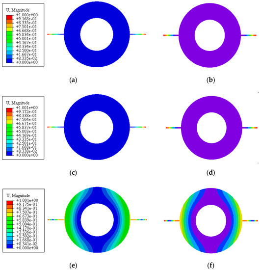
Figure 6.
Vibration modes of the double-bladed disk system: (a,c,e) First three mode obtained by ABAQUS, (b,d,f) First three mode obtained by MATLAB.
3.2. Free Vibration Analysis
In what follows, the effects of the material and structural parameters on the free vibration of the double-bladed disk are examined in detail. Figure 7 depicts the changes of first three traveling wave frequencies of the double-bladed disk system with spinning speed for different distributions of GPLs and porosity in the disk, where the distributions of GPLs and porosity in the blades remain XGB and XPB; different color lines stand for different GPL distributions; different type lines stand for different porosity distributions; two different marks in the lines stand for backward and forward traveling wave frequencies. As can be seen, the first forward traveling wave frequency decreases first and then rises, while the first backward traveling wave frequency increases monotonously. The second and third forward traveling wave frequencies are decreased continuously, while the second and third backward traveling wave frequencies grow on and on. Another observation is that the porosity distribution XPD and GPL distribution XGD provide the largest frequencies compared to other porosity and GPL distributions. It indicates that dispersing more GPLs around the surfaces of the disk is effective to improving the mechanical performance of the double-bladed disk system. Meanwhile, the non-uniform porosity distribution XPD can help to achieve the highest structural stiffness. It can be found that the GPL distribution patterns in the disk have a greater influence on the traveling wave frequencies than porosity distribution patterns. Moreover, the third traveling wave frequency is affected markedly by the GPL and porosity distribution in the disk, while the first two traveling wave frequencies are impacted little. This is because the vibration mode corresponding to the third frequency contains obvious disk vibration, as shown in Figure 6.
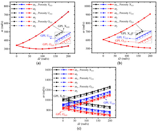
Figure 7.
Effects of graphene nanoplatelet (GPL) and porosity distribution in the disk on the traveling wave frequencies of the double-bladed system: (a) First frequency, (b) Second frequency, (c) Third frequency.
Figure 8 plots the changes of first three traveling wave frequencies of the double-bladed disk system with spinning speed for different distributions of GPLs and porosity in the blades, where the distributions of GPLs and porosity in the disk remain XGD and XPD. It can be seen that the rotor system with porosity distribution XPB and GPL distribution XGB has largest traveling wave frequencies.
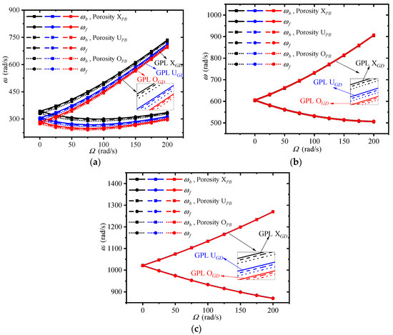
Figure 8.
Effects of GPL and porosity distribution in the disk on the traveling wave frequencies of the double-bladed system: (a) First frequency, (b) Second frequency, (c) Third frequency.
This implies that adding more GPLs around the surfaces of the blades has an obvious advantage to enhance the rotor stiffness. It can be told that the non-uniform pattern XPB is the best candidate among the presented porosity distributions. The traveling wave frequencies are more sensitive to the GPL distribution patterns in the blades than porosity distributions. In addition, the GPL and porosity distribution in the blades mostly affect the first traveling wave frequency, which is because the vibration mode corresponding to the first frequency is mainly reflected by the blades’ displacements along their thickness direction.
Since the variations of forward and backward traveling frequencies exhibit quite a similar trend, only the backward traveling frequencies under two typical spinning speeds—0 rad/s and 100 rad/s—are listed in Table 5, Table 6, Table 7 and Table 8.
Table 5.
Effect of GPL weight fraction on the backward traveling frequencies (rad/s) of the double-bladed system at different spinning speeds (rad/s).
Table 6.
Effect of GPL length-to-thickness ratio on the backward traveling frequencies (rad/s) of the double-bladed system at different spinning speeds (rad/s).
Table 7.
Effect of GPL length-to-width ratio on the backward traveling frequencies (rad/s) of the double-bladed system at different spinning speeds (rad/s).
Table 8.
Effect of porosity coefficient on the backward traveling frequencies (rad/s) of the double-bladed system at different spinning speeds (rad/s).
Table 5 shows the first three traveling wave frequencies of the double-bladed disk system for different GPL weight fractions, where (p = 0, q = f), (p = f, q = 0), and (p = q = f) stand for only blades are reinforced, only disk is reinforced, and both blades and disk are equally reinforced by GPLs. A considerable rise in the traveling wave frequencies is observed as the GPL weight fraction increases, which indicates that dispersing more GPLs at a low total content can achieve better mechanical performance of the double-bladed disk system. In addition, the first two frequencies are mainly influenced by the GPL weight fraction in the blades, while the third frequency is mostly affected by that in the disk.
Table 6 lists the first three traveling wave frequencies of the double-bladed disk system for different GPL length-to-thickness ratios. A higher GPL length-to-thickness ratio leads to increased traveling wave frequencies. For the same content of GPLs, larger values of GPL length-to-thickness ratio mean thinner GPLs. Thus, it can be noted that adopting thinner GPLs is effective in improving the vibration behavior of double-bladed disk system. Similar to the GPL weight fraction, the first two frequencies are more sensitive to the GPL length-to-thickness ratio in the blades.
Table 7 gives the first three traveling wave frequencies of the double-bladed disk system for different GPL length-to-width ratios, where GPL length remains constant. Actually, lower GPL length-to-width ratios represent GPLs with larger surface areas. It is obvious that the traveling wave frequencies decrease with the increase of the GPL length-to-width ratio. This is because larger surface contact areas between the matrix and GPLs lead to better load transfer capacity. In addition, the first two frequencies and third frequency are primarily impacted by the GPL length-to-width ratio in the blades and disk, respectively.
Table 8 shows the first three traveling wave frequencies of the double-bladed disk system for different porosity coefficients. It is seen that the traveling wave frequencies are reduced in general with an increase in the porosity coefficient. A greater porosity coefficient means more and larger pores in the matrix, which weaken the stiffness of the double-bladed disk system, and the first two frequencies and third frequency are mainly determined by the porosity coefficient in the blades and disk, respectively. However, an interesting phenomenon occurs in third frequency (p = 0, q = f): the frequency has a slight rise when the porosity coefficient in the blades increases solely.
Figure 9 plots the changes of first three traveling wave frequencies of the double-bladed disk system with spinning speeds for different disk inner radiuses and blade lengths, where the disk outer radius keeps constant. Increasing the disk inner radius and decreasing the blade length results in the rise of the traveling wave frequencies. It implies that a larger disk inner radius and shorter blade length in comparison with the disk outer radius should be designed to achieve better structural stiffness. Moreover, it can be found that the disk inner radius majorly influences the third frequency, while the blade length chiefly affects the first two frequencies.

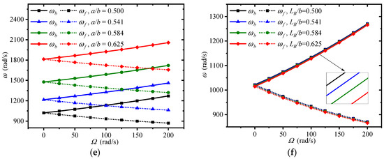
Figure 9.
Effects of disk inner radius and blade length on the traveling wave frequencies of the double-bladed system: (a,b) First frequency, (c,d) Second frequency, (e,f) Third frequency.
4. Conclusions
In this paper, the coupled free vibration behavior of a spinning FG-GPLRC porous double-bladed disk system has been investigated for the first time. Based on Euler–Bernoulli beam theory and Kirchhoff plate theory, the equations of motion are derived by adopting the Lagrange equation method, which are solved by the substructure mode synthesis method and the assumed modes method. It is found from numerical results that using non-uniform porosity patterns XPD and XPB and dispersing more GPLs near the surfaces of the disk and blades are the most effective way to improve the structural stiffness and mechanical performance of the double-bladed disk system. The first traveling wave frequency is primarily influenced by the GPL and porosity distribution in the blades, while the third traveling wave frequency is remarkedly affected by those in the disk. A better reinforcement effect can be achieved when thinner GPLs with larger surface areas are used. In general, the traveling wave frequencies become lower at a higher porosity. However, the third-order frequency increases slightly when only the porosity in the blades increases. In addition, the first two frequencies are considerably influenced by the weight fraction, length-to-thickness ratio, and length-to-width ratio of GPLs, porosity coefficient, and the length of the blades, while the third-order frequency is mainly affected by those factors and the inner radius of the disk.
Author Contributions
Conceptualization, T.Z. and J.Y.; methodology, T.Z. and Y.M.; software, Y.M.; validation, H.Z.; formal analysis, H.Z.; investigation, T.Z. and Y.M.; resources, T.Z.; data curation, Y.M.; writing—original draft preparation, T.Z.; writing—review and editing, J.Y.; visualization, Y.M.; supervision, J.Y.; project administration, T.Z. and H.Z.; funding acquisition, T.Z. and H.Z. All authors have read and agreed to the published version of the manuscript.
Funding
This project is funded by the National Science Foundation of China (No. 51805076, No. U1708255 and No. 51775093).
Conflicts of Interest
The authors declare no conflict of interest.
Appendix A
The specific expressions of each element in the mass matrix M, gyroscopic matrix G, and stiffness matrix K.
References
- Chen, Y.G.; Zhai, J.Y.; Han, Q.K. Vibration and damping analysis of the bladed disk with damping hard coating on blades. Aerosp. Sci. Technol. 2016, 58, 248–257. [Google Scholar] [CrossRef]
- Zhao, T.Y.; Yuan, H.Q.; Li, B.B.; Li, Z.J.; Liu, L.M. Analytical solution for rotational rub-impact plate under thermal shock. J. Mech. 2016, 32, 297–311. [Google Scholar] [CrossRef]
- AI-Khudairi, O.; Hadavinia, H.; Little, C.; Gillmore, G.; Greaves, P.; Dyer, K. Full-scale fatigue testing of a wind turbine blade in flapwise direction and examining the effect of crack propagation on the blade performance. Materials 2017, 10, 1152. [Google Scholar] [CrossRef] [PubMed]
- Wieland, B.; Ropte, S. Process modeling of composite materials for wind-turbine rotor blades: Experiments and numerical modeling. Materials 2017, 10, 1157. [Google Scholar] [CrossRef]
- Zhao, T.Y.; Yuan, H.Q.; Yang, W.J.; Sun, H.G. Genetic particle swarm parallel algorithm analysis of optimization arrangement on mistuned blades. Eng. Optim. 2017, 49, 2095–2116. [Google Scholar] [CrossRef]
- Zhao, T.Y.; Li, H.X.; Sun, H.G. Parallel intelligent algorithm analysis of optimization arrangement on mistuned blades based on compute unified device architecture. Proc. Inst. Mech. Eng. Part G J. Aerosp. Eng. 2019, 233, 2207–2218. [Google Scholar] [CrossRef]
- Ma, H.; Wang, D.; Tai, X.Y.; Wen, B.C. Vibration response analysis of blade-disk dovetail structure under blade tip rubbing condition. J. Vib. Control 2017, 23, 252–271. [Google Scholar] [CrossRef]
- Battiato, G.; Firrone, C.M.; Berruti, T.M. Forced response of rotating bladed disks: Blade tip-timing measurements. Mech. Syst. Signal Process. 2017, 85, 912–926. [Google Scholar] [CrossRef]
- Bai, B.; Li, H.; Zhang, W.; Cui, Y.C. Application of extremum response surface method-based improved substructure component modal synthesis in mistuned turbine bladed disk. J. Sound Vib. 2020, 472, 115210. [Google Scholar] [CrossRef]
- Rafiee, M.A.; Rafiee, J.; Wang, Z.; Song, H.H.; Yu, Z.Z.; Koratkar, N. Enhanced mechanical properties of nanocomposites at low graphene content. ACS Nano 2009, 3, 3884–3890. [Google Scholar] [CrossRef]
- Liu, D.Y.; Kitipornchai, S.; Chen, W.Q.; Yang, J. Three-dimensional buckling and free vibration analyses of initially stressed functionally graded graphene reinforced composite cylindrical shell. Compos. Struct. 2018, 189, 560–569. [Google Scholar] [CrossRef]
- Reddy, R.M.R.; Karunasena, W.; Lokuge, W. Free vibration of functionally graded-GPL reinforced composite plates with different boundary conditions. Aerosp. Sci. Technol. 2018, 78, 147–156. [Google Scholar] [CrossRef]
- Zhao, T.Y.; Wang, Y.X.; Pan, H.G.; Gao, X.S.; Cai, Y. Analytical solution for vibration characteristics of rotating graphene nanoplatelet-reinforced plates under rub-impact and thermal shock. Adv. Compos. Lett. 2020, 29. [Google Scholar] [CrossRef]
- Amirabadi, H.; Farhatnia, F.; Eftekhari, S.A.; Hosseini-Ara, R. Free vibration analysis of rotating functionally graded GPL-reinforced truncated thick conical shells under different boundary conditions. Mech. Based Des. Struct. Mach. 2020. [Google Scholar] [CrossRef]
- Feng, C.; Kitipornchai, S.; Yang, J. Nonlinear free vibration of functionally graded polymer composite beams reinforced with graphene nanoplatelets (GPLs). Eng. Struct. 2017, 140, 110–119. [Google Scholar] [CrossRef]
- Tam, M.F.; Yang, T.Z.; Zhao, S.Y.; Yang, J. Vibration and buckling characteristics of functionally graded graphene nanoplatelets reinforced composite beams with open edge cracks. Materials 2019, 12, 1412. [Google Scholar] [CrossRef]
- Zhao, Z.; Feng, C.; Wang, Y.; Yang, J. Bending and vibration analysis of functionally graded trapezoidal nanocomposite plates reinforced with graphene nanoplatelets (GPLs). Compos. Struct. 2017, 180, 799–808. [Google Scholar] [CrossRef]
- Guo, H.L.; Cao, S.Q.; Yang, T.Z.; Chen, Y.S. Vibration of laminated composite quadrilateral plates reinforced with graphene nanoplatelets using the element-free IMLS-Ritz method. Int. J. Mech. Sci. 2018, 142, 610–621. [Google Scholar] [CrossRef]
- Wu, H.L.; Zhu, J.; Kitipornchai, S.; Wang, Q.; Ke, L.L.; Yang, J. Large amplitude vibration of functionally graded graphene nanocomposite annular plates in thermal environments. Compos. Struct. 2020, 239, 112047. [Google Scholar] [CrossRef]
- Song, M.T.; Gong, Y.H.; Yang, J.; Zhu, W.D.; Kitipornchai, S. Nonlinear free vibration of cracked functionally graded graphene platelet-reinforced nanocomposite beams in thermal environments. J. Sound Vib. 2020, 468, 115115. [Google Scholar] [CrossRef]
- Yang, Z.C.; Zhao, S.Y.; Yang, J.; Lv, J.G.; Liu, A.R.; Fu, J.Y. In-plane and out-of-plane free vibrations of functionally graded composite arches with graphene reinforcements. Mech. Adv. Mater. Struct. 2020. [Google Scholar] [CrossRef]
- Wattanasakulpong, N.; Ungbhakorn, V. Linear and nonlinear vibration analysis of elastically restrained ends FGM beams with porosities. Aerosp. Sci. Technol. 2014, 32, 111–120. [Google Scholar] [CrossRef]
- Wang, Y.Q.; Zu, J.W. Large-amplitude vibration of sigmoid functionally graded thin plates with porosities. Thin Walled Struct. 2017, 119, 911–924. [Google Scholar] [CrossRef]
- Ebrahimi, F.; Ghasemi, F.; Salari, E. Investigating thermal effects on vibration behavior of temperature-dependent compositionally graded Euler beams with porosities. Meccanica 2016, 51, 223–249. [Google Scholar] [CrossRef]
- Wang, Y.W.; Wu, D.F. Free vibration of functionally graded porous cylindrical shell using a sinusoidal shear deformation theory. Aerosp. Sci. Technol. 2017, 66, 83–91. [Google Scholar] [CrossRef]
- Ebrahimi, F.; Zia, M. Large amplitude nonlinear vibration analysis of functionally graded Timoshenko beams with porosities. Acta Astronaut. 2015, 116, 117–125. [Google Scholar] [CrossRef]
- Wang, Y.Q.; Zu, J.W. Vibration behaviors of functionally graded rectangular plates with porosities and moving in thermal environment. Aerosp. Sci. Technol. 2017, 69, 550–562. [Google Scholar] [CrossRef]
- Kim, J.; Zur, K.K.; Reddy, J.N. Bending, free vibration, and buckling of modified couples stress-based functionally graded porous micro-plates. Compos. Struct. 2019, 209, 879–888. [Google Scholar] [CrossRef]
- Chen, D.; Yang, J.; Kitipornchai, S. Nonlinear vibration and postbuckling of functionally graded graphene reinforced porous nanocomposite beams. Compos. Sci. Technol. 2017, 142, 235–245. [Google Scholar] [CrossRef]
- Dong, Y.H.; Li, Y.H.; Chen, D.; Yang, J. Vibration characteristics of functionally graded graphene reinforced porous nanocomposite cylindrical shells with spinning motion. Compos. Part B Eng. 2018, 145, 1–13. [Google Scholar] [CrossRef]
- Kitipornchai, S.; Chen, D.; Yang, J. Free vibration and elastic buckling of functionally graded porous beams reinforced by graphene platelets. Mater. Des. 2017, 116, 656–665. [Google Scholar] [CrossRef]
- Zhao, S.Y.; Zhao, Z.; Yang, Z.C.; Ke, L.L.; Kitipornchai, S.; Yang, J. Functionally graded graphene reinforced composite structures: A review. Eng. Struct. 2020, 210, 110339. [Google Scholar] [CrossRef]
Publisher’s Note: MDPI stays neutral with regard to jurisdictional claims in published maps and institutional affiliations. |
© 2020 by the authors. Licensee MDPI, Basel, Switzerland. This article is an open access article distributed under the terms and conditions of the Creative Commons Attribution (CC BY) license (http://creativecommons.org/licenses/by/4.0/).