Characterization and Optimization of Elastomeric Electrodes for Dielectric Elastomer Artificial Muscles


Abstract
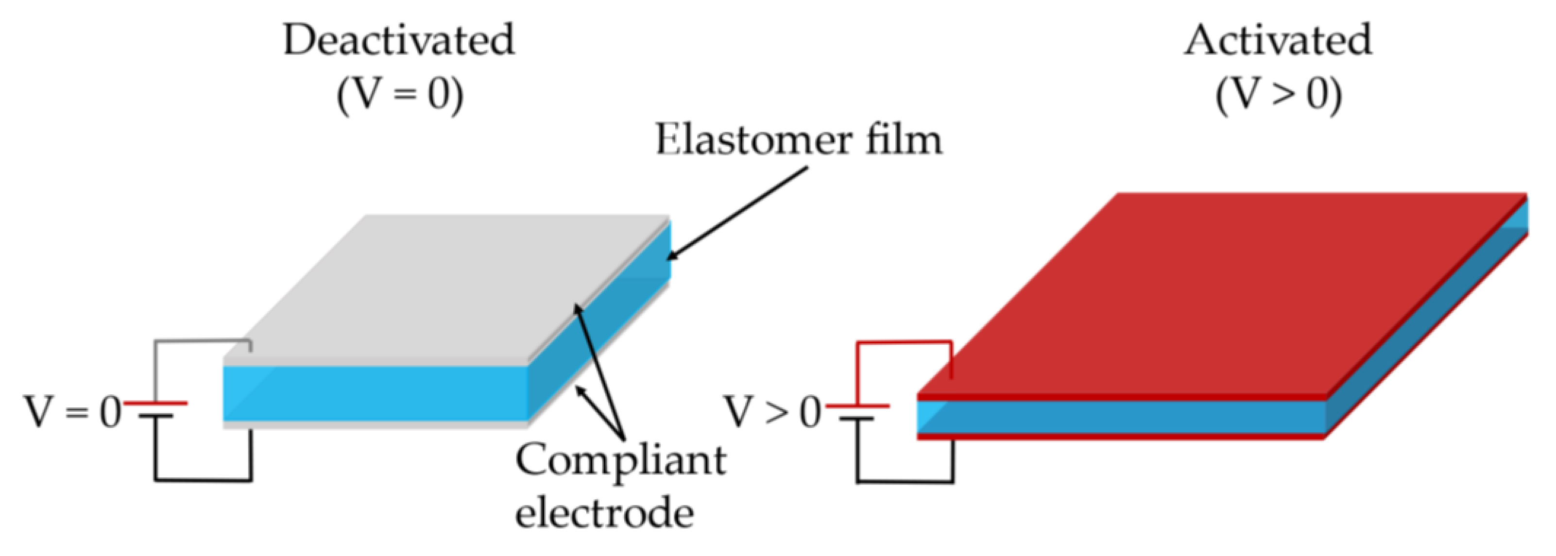
1. Introduction
2. Materials and Methods
2.1. Materials
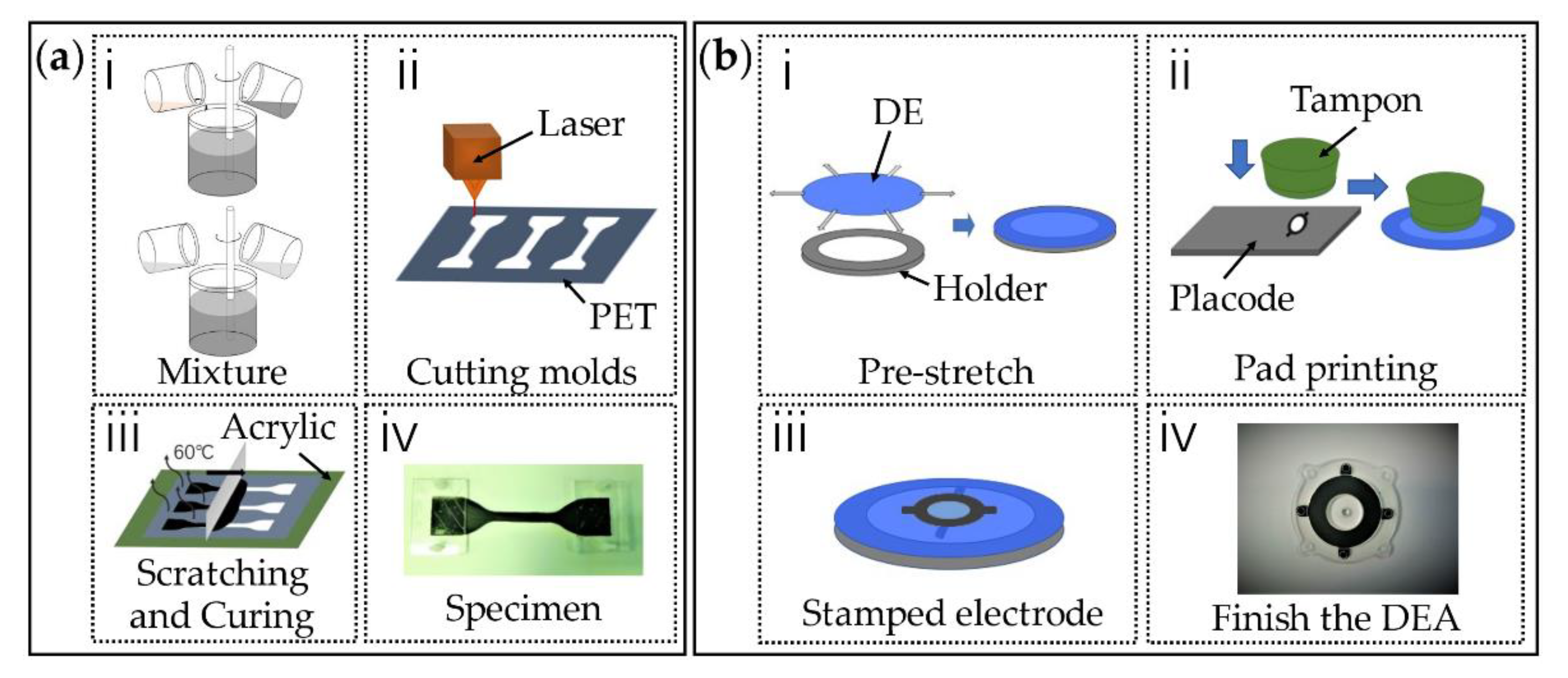
2.2. Preparation of Specimen
2.3. Testing Methods
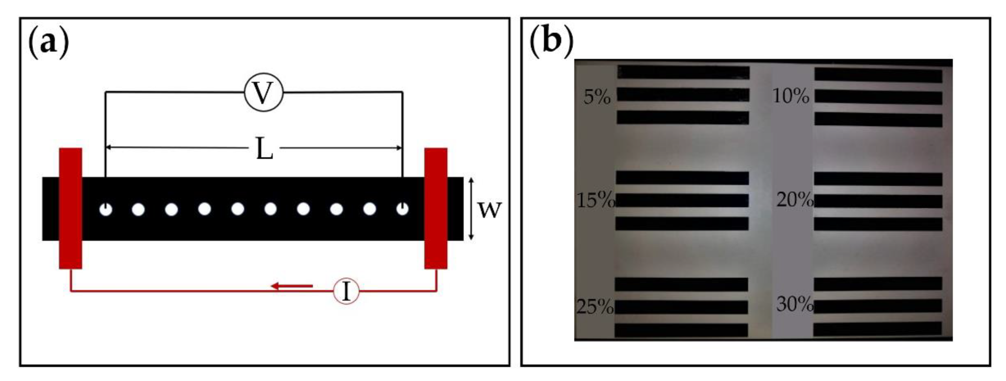
2.3.1. Electrical Conductivity Test
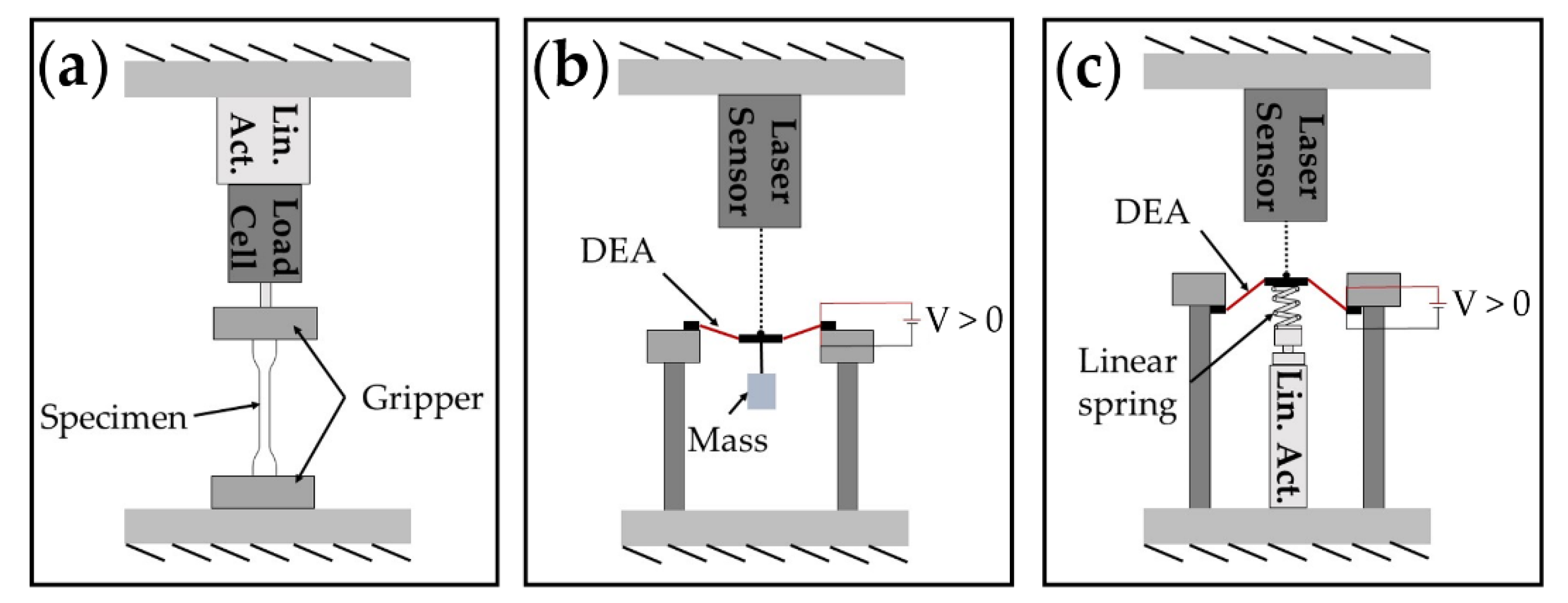
2.3.2. Uniaxial Tensile Test and Dielectric Elastomer Actuator (DEA) Actuation Test
3. Results
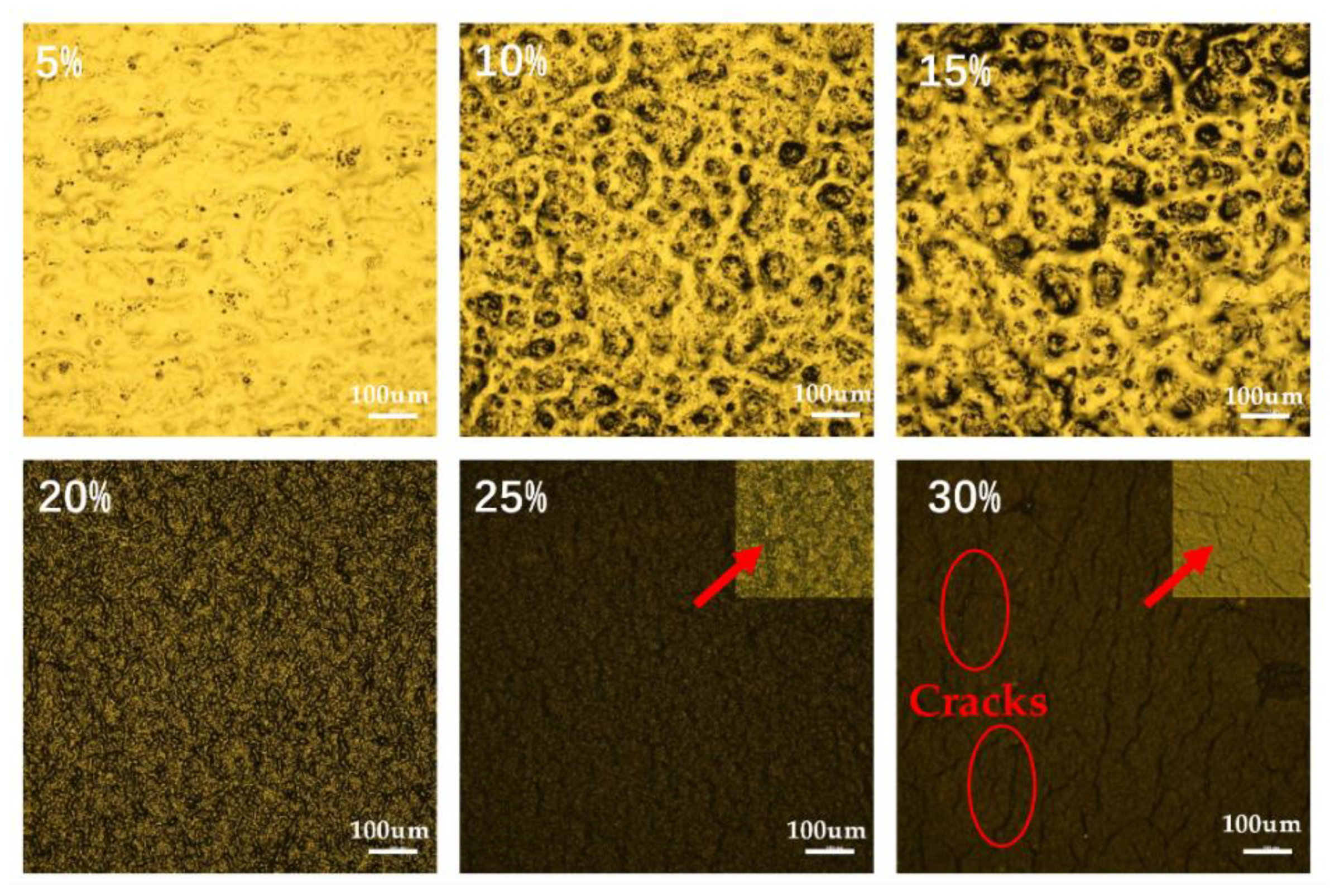
3.1. Morphology Characterization
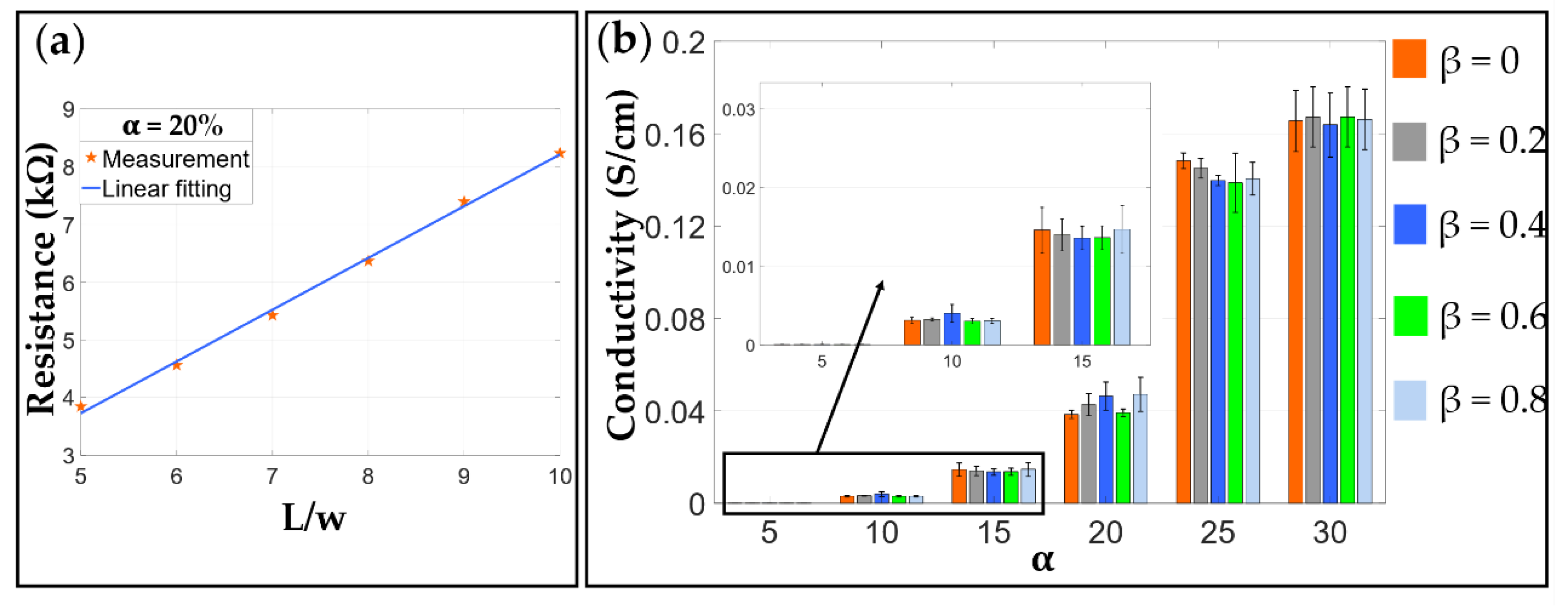
3.2. Electrical Characterization
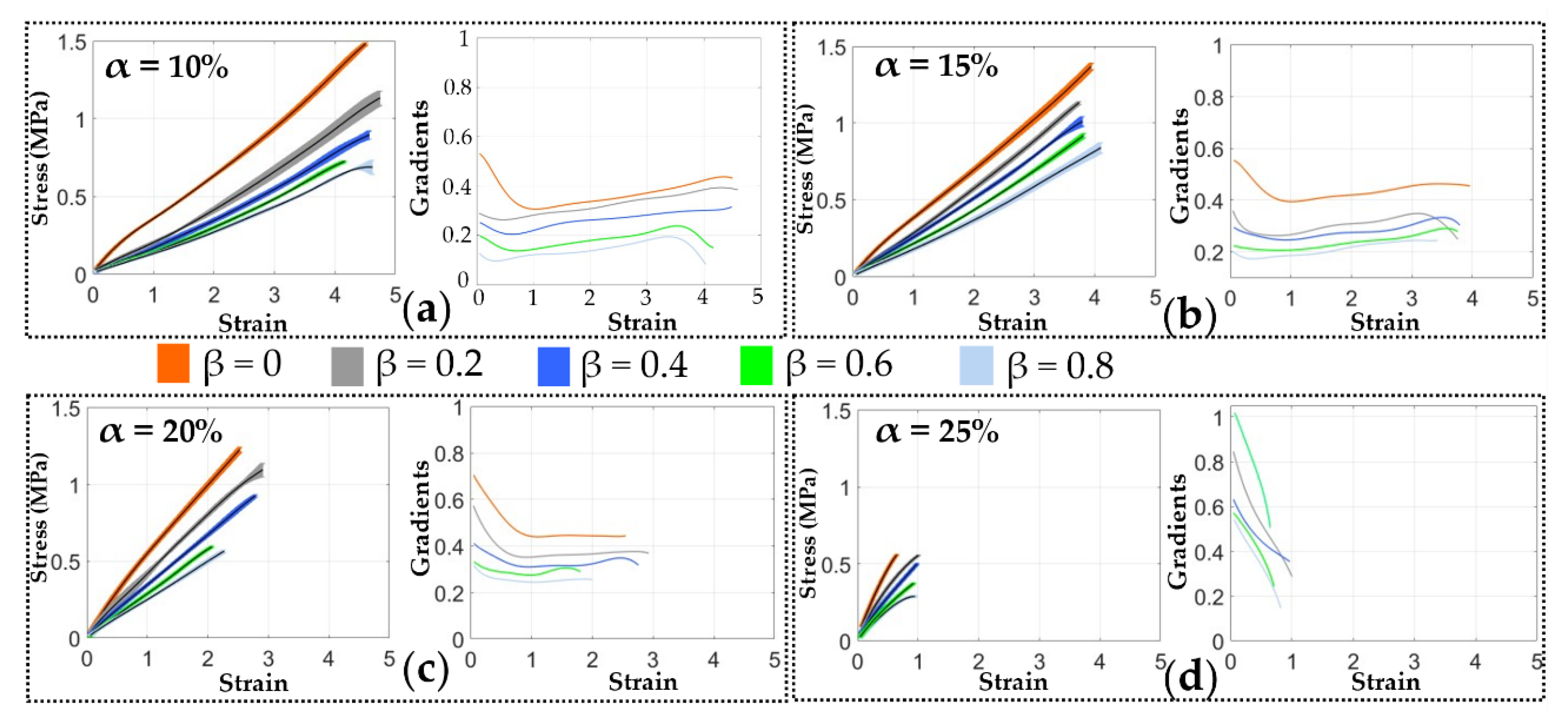
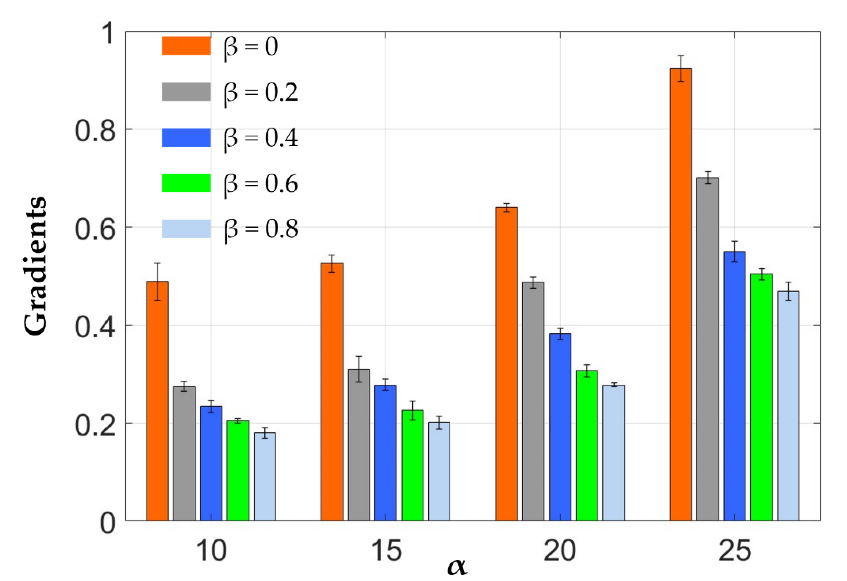
3.3. Mechanical Characterization
4. Discussion
5. Conclusions
- Increasing the CB ratio increases the electrical conductivity of the electrode and the stiffness of the elastomeric electrode but reduces the elongation at break ratio.
- Increasing the Ecoflex 20 to RT 625 ratio can decrease the stiffness of the elastomeric electrode yet shows no clear effects on the elongation at break ratio.
- Adding Ecoflex 20 to the electrode formula can significantly increase the pot life of the electrode mixture.
- In quasi-static actuation scenarios, electrode stiffness plays the most important role in DEA’s output performance.
- In high-frequency actuation scenarios, electrode conductivity is the key factor determining the DEA’s output performance.
- The research is the first to analyze the influence of electrode stiffness and conductivity on DEA output performances in different application scenarios.
- The research developed an optimization method for elastomeric electrode formulas based on different application scenarios (e.g., α = 10 wt.%, β = 0.8:1 for quasi-static and α = 25 wt.%, β = 0.8:1 for high-frequency cases).
Supplementary Materials
Author Contributions
Funding
Conflicts of Interest
References
- Pelrine, R.; Kornbluh, R.; Pei, Q.B.; Joseph, J. High-speed electrically actuated elastomers with strain greater than 100%. Science 2000, 287, 836–839. [Google Scholar] [CrossRef]
- Gu, G.Y.; Zhu, J.; Zhu, L.M.; Zhu, X. A survey on dielectric elastomer actuators for soft robots. Bioinspiration Biomim. 2017, 12, 011003. [Google Scholar] [CrossRef]
- Huang, J.; Shian, S.; Suo, Z.; Clarke, D.R. Maximizing the Energy Density of Dielectric Elastomer Generators Using Equi-Biaxial Loading. Adv. Funct. Mater. 2013, 23, 5056–5061. [Google Scholar] [CrossRef]
- Koh, S.J.A.; Keplinger, C.; Li, T.; Bauer, S.; Suo, Z. Dielectric Elastomer Generators: How Much Energy Can Be Converted? IEEE/ASME Trans. Mechatron. 2011, 16, 33–41. [Google Scholar] [CrossRef]
- Gao, X.; Cao, C.; Guo, J.; Conn, A. Elastic Electroadhesion with Rapid Release by Integrated Resonant Vibration. Adv. Mater. Technol. 2019, 4, 1800378. [Google Scholar] [CrossRef]
- Cao, C.-J.; Hill, T.L.; Conn, A.T.; Li, B.; Gao, X. Nonlinear Dynamics of a Magnetically Coupled Dielectric Elastomer Actuator. Phys. Rev. Appl. 2019, 12, 044033. [Google Scholar] [CrossRef]
- Bar-Cohen, Y.; Yu, L.; Gonzalez, L.B.; Hvilsted, S.; Skov, A.L. Soft silicone based interpenetrating networks as materials for actuators. In Proceedings of the SPIE Smart Structures and Materials + Nondestructive Evaluation and Health Monitoring, San Diego, CA, USA, 9–13 March 2014. [Google Scholar]
- Chen, Y.; Zhao, H.; Mao, J.; Chirarattananon, P.; Helbling, E.F.; Hyun, N.P.; Clarke, D.R.; Wood, R.J. Controlled flight of a microrobot powered by soft artificial muscles. Nature 2019, 575, 324–329. [Google Scholar] [CrossRef] [PubMed]
- Cao, C.; Gao, X.; Conn, A.T. A Magnetically Coupled Dielectric Elastomer Pump for Soft Robotics. Adv. Mater. Technol. 2019, 4, 1900128. [Google Scholar] [CrossRef]
- Cao, C.; Gao, X.; Conn, A.T. A compliantly coupled dielectric elastomer actuator using magnetic repulsion. Appl. Phys. Lett. 2019, 114, 011904. [Google Scholar] [CrossRef]
- Ji, X.B.; Liu, X.C.; Cacucciolo, V.; Imboden, M.; Civet, Y.; El Haitami, A.; Cantin, S.; Perriard, Y.; Shea, H. An autonomous untethered fast soft robotic insect driven by low-voltage dielectric elastomer actuators. Sci. Robot. 2019, 4, eaaz6451. [Google Scholar] [CrossRef] [PubMed]
- Cao, C.; Gao, X.; Burgess, S.; Conn, A.T. Power optimization of a conical dielectric elastomer actuator for resonant robotic systems. Extrem. Mech. Lett. 2020, 35, 100619. [Google Scholar] [CrossRef]
- Shintake, J.; Rosset, S.; Schubert, B.; Floreano, D.; Shea, H. Versatile Soft Grippers with Intrinsic Electroadhesion Based on Multifunctional Polymer Actuators. Adv. Mater. 2016, 28, 231–238. [Google Scholar] [CrossRef] [PubMed]
- Bozlar, M.; Punckt, C.; Korkut, S.; Zhu, J.; Chiang Foo, C.; Suo, Z.; Aksay, I.A. Dielectric elastomer actuators with elastomeric electrodes. Appl. Phys. Lett. 2012, 101, 091907. [Google Scholar] [CrossRef]
- Matysek, M.; Lotz, P.; Winterstein, T.; Schlaak, H.F. Dielectric Elastomer Actuators for Tactile Displays. In Proceedings of the World Haptics 2009: Third Joint Eurohaptics Conference and Symposium on Haptic Interfaces for Virtual Environment and Teleoperator Systems, Salt Lake City, UT, USA, 18–20 March 2009; pp. 290–295. [Google Scholar]
- Luo, M.; Liu, L.; Liu, C.; Li, B.; Cao, C.; Gao, X.; Li, D. A single-chamber pneumatic soft bending actuator with increased stroke-range by local electric guidance. IEEE Trans. Ind. Electron. 2020, 2020, 1. [Google Scholar] [CrossRef]
- Cao, C.; Hill, T.L.; Conn, A.T. On the nonlinear dynamics of a circular dielectric elastomer oscillator. Smart Mater. Struct. 2019, 28, 075020. [Google Scholar] [CrossRef]
- Kuhnel, D.T.; Rossiter, J.M.; Faul, C.F.J. Laser-Scribed Graphene Oxide Electrodes for Soft Electroactive Devices. Adv. Mater. Technol. 2019, 4, 1800232. [Google Scholar] [CrossRef]
- Bannych, A.; Katz, S.; Barkay, Z.; Lachman, N. Preserving Softness and Elastic Recovery in Silicone-Based Stretchable Electrodes Using Carbon Nanotubes. Polymers 2020, 12, 1345. [Google Scholar] [CrossRef]
- Huang, J.-C. Carbon black filled conducting polymers and polymer blends. Adv. Polym. Technol. 2002, 21, 299–313. [Google Scholar] [CrossRef]
- Rosset, S.; Shea, H.R. Flexible and stretchable electrodes for dielectric elastomer actuators. Appl. Phys. A 2012, 110, 281–307. [Google Scholar] [CrossRef]
- Rosset, S.; De Saint-Aubin, C.; Poulin, A.; Shea, H.R. Assessing the degradation of compliant electrodes for soft actuators. Rev. Sci. Instrum. 2017, 88, 105002. [Google Scholar] [CrossRef]
- De Saint-Aubin, C.A.; Rosset, S.; Schlatter, S.; Shea, H. High-cycle electromechanical aging of dielectric elastomer actuators with carbon-based electrodes. Smart Mater. Struct. 2018, 27, 074002. [Google Scholar] [CrossRef]
- Schlatter, S.; Rosset, S.; Shea, H. Inkjet printing of carbon black electrodes for dielectric elastomer actuators. In Proceedings of the SPIE Smart Structures and Materials + Nondestructive Evaluation and Health Monitoring, Portland, OR, USA, 25–29 March 2017; Volume 2017, p. 10163. [Google Scholar]
- Zhang, J.; Sheng, J.; Liu, X.; Liu, L.; Zhao, J.; Chen, H. Temperature effect on electromechanical properties of polyacrylic dielectric elastomer: An experimental study. Smart Mater. Struct. 2020, 29, 047002. [Google Scholar] [CrossRef]
- Zhang, J.; Liu, X.; Liu, L.; Yang, Z.; Li, P.; Chen, H. Modeling and experimental study on dielectric elastomers incorporating humidity effect. EPL (Europhys. Lett.) 2020, 129, 57002. [Google Scholar] [CrossRef]
- Zhang, J.; Liu, L.; Chen, H. Electromechanical properties of soft dissipative dielectric elastomer actuators influenced by electrode thickness and conductivity. J. Appl. Phys. 2020, 127, 184902. [Google Scholar] [CrossRef]
- Lau, G.-K.; Lim, H.-T.; Teo, J.-Y.; Chin, Y.-W. Lightweight mechanical amplifiers for rolled dielectric elastomer actuators and their integration with bio-inspired wing flappers. Smart Mater. Struct. 2014, 23, 025021. [Google Scholar] [CrossRef]
- McCoul, D.; Hu, W.; Gao, M.; Mehta, V.; Pei, Q. Recent Advances in Stretchable and Transparent Electronic Materials. Adv. Electron. Mater. 2016, 2, 1500407. [Google Scholar] [CrossRef]
- Gao, X.; Shi, Z.; Liu, C.; Yang, G.; Sevostianov, I.; Silberschmidt, V.V. Inelastic behaviour of bacterial cellulose hydrogel: In aqua cyclic tests. Polym. Test. 2015, 44, 82–92. [Google Scholar] [CrossRef]
- Carpi, F.; A Anderson, I.; Bauer, S.; Frediani, G.; Gallone, G.; Gei, M.; Graaf, C.; Jean-Mistral, C.; Kaal, W.; Kofod, G.; et al. Standards for dielectric elastomer transducers. Smart Mater. Struct. 2015, 24, 105025. [Google Scholar] [CrossRef]
- Tang, C.; Ma, W.; Li, B.; Jin, M.; Chen, H. Cephalopod-Inspired Swimming Robot Using Dielectric Elastomer Synthetic Jet Actuator. Adv. Eng. Mater. 2019, 22, 1901130. [Google Scholar] [CrossRef]
- Yang, T.; Xiao, Y.; Zhang, Z.; Liang, Y.; Li, G.; Zhang, M.; Li, S.; Wong, T.W.; Wang, Y.; Li, T.; et al. A soft artificial muscle driven robot with reinforcement learning. Sci. Rep. 2018, 8, 14518. [Google Scholar] [CrossRef]
- Xu, C.; Stiubianu, G.T.; Gorodetsky, A.A. Adaptive infrared-reflecting systems inspired by cephalopods. Science 2018, 359, 1495–1500. [Google Scholar] [CrossRef] [PubMed]
- Linnebach, P.; Rizzello, G.; Seelecke, S. Design and validation of a dielectric elastomer membrane actuator driven pneumatic pump. Smart Mater. Struct. 2020, 29. [Google Scholar] [CrossRef]


| Conductivity (S/cm) | α | ||||
|---|---|---|---|---|---|
| 10% | 15% | 20% | 25% | ||
| β | 0 | 0.0031 0.0004 | 0.0145 0.0035 | 0.0384 0.0021 | 0.1482 0.0041 |
| 0.2 | 0.0032 0.0002 | 0.0139 0.0024 | 0.0427 0.0058 | 0.1449 0.0051 | |
| 0.4 | 0.0039 0.0013 | 0.0135 0.0018 | 0.0463 0.0075 | 0.1397 0.0027 | |
| 0.6 | 0.0030 0.0004 | 0.0135 0.0019 | 0.0401 0.0019 | 0.1387 0.0157 | |
| 0.8 | 0.0030 0.0003 | 0.0146 0.0037 | 0.0471 0.0090 | 0.1404 0.0086 | |
| Tensile Modulus (MPa) | α | ||||
|---|---|---|---|---|---|
| 10% | 15% | 20% | 25% | ||
| β | 0 | 0.489 0.038 | 0.526 0.018 | 0.640 0.008 | 0.026 |
| 0.2 | 0.285 0.010 | 0.310 0.026 | 0.487 0.011 | 0.701 0.013 | |
| 0.4 | 0.234 0.012 | 0.278 0.012 | 0.382 0.012 | 0.550 0.021 | |
| 0.6 | 0.205 0.005 | 0.226 0.019 | 0.297 0.012 | 0.504 0.011 | |
| 0.8 | 0.180 0.011 | 0.201 0.013 | 0.278 0.004 | 0.469 0.019 | |
| Samples | α | β | Conductivity (S/cm) | Tensile Modulus (MPa) |
|---|---|---|---|---|
| Formula (1) | 10 | 0.2:1 | 0.0032 | 0.285 |
| Formula (2) | 20 | 0.2:1 | 0.0427 | 0.487 |
| Formula (3) | 20 | 0.6:1 | 0.0401 | 0.297 |
Publisher’s Note: MDPI stays neutral with regard to jurisdictional claims in published maps and institutional affiliations. |
© 2020 by the authors. Licensee MDPI, Basel, Switzerland. This article is an open access article distributed under the terms and conditions of the Creative Commons Attribution (CC BY) license (http://creativecommons.org/licenses/by/4.0/).
Share and Cite
Ma, G.; Wu, X.; Chen, L.; Tong, X.; Zhao, W. Characterization and Optimization of Elastomeric Electrodes for Dielectric Elastomer Artificial Muscles. Materials 2020, 13, 5542. https://doi.org/10.3390/ma13235542
Ma G, Wu X, Chen L, Tong X, Zhao W. Characterization and Optimization of Elastomeric Electrodes for Dielectric Elastomer Artificial Muscles. Materials. 2020; 13(23):5542. https://doi.org/10.3390/ma13235542
Chicago/Turabian StyleMa, Guangqiang, Xiaojun Wu, Lijin Chen, Xin Tong, and Weiwei Zhao. 2020. "Characterization and Optimization of Elastomeric Electrodes for Dielectric Elastomer Artificial Muscles" Materials 13, no. 23: 5542. https://doi.org/10.3390/ma13235542
APA StyleMa, G., Wu, X., Chen, L., Tong, X., & Zhao, W. (2020). Characterization and Optimization of Elastomeric Electrodes for Dielectric Elastomer Artificial Muscles. Materials, 13(23), 5542. https://doi.org/10.3390/ma13235542