Development of Self-Healing Cement Slurry through the Incorporation of Dual-Encapsulated Polyacrylamide for the Prevention of Water Ingress in Oil Well

 ,
, 
Abstract
:
1. Introduction
2. Materials and Methods
2.1. Materials
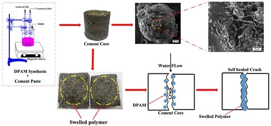
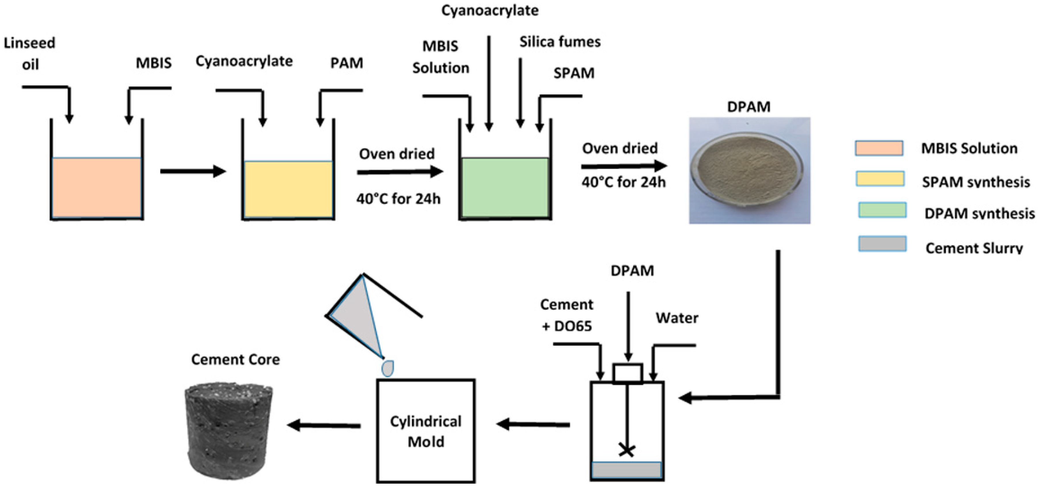
2.2. Synthesis of Dual Coated SAP and Cement Core
2.3. Water-Absorption Test
2.4. Characterization
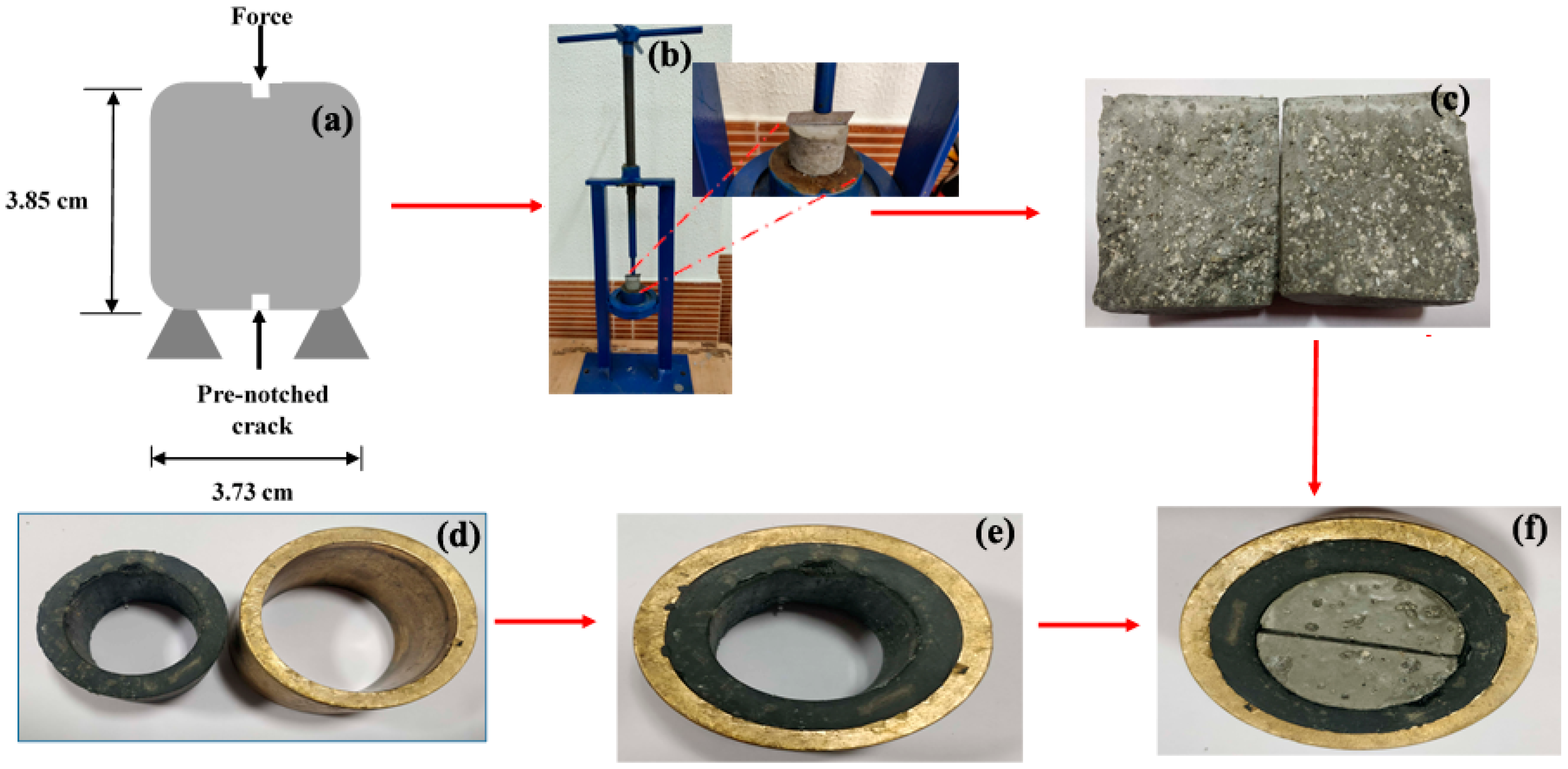
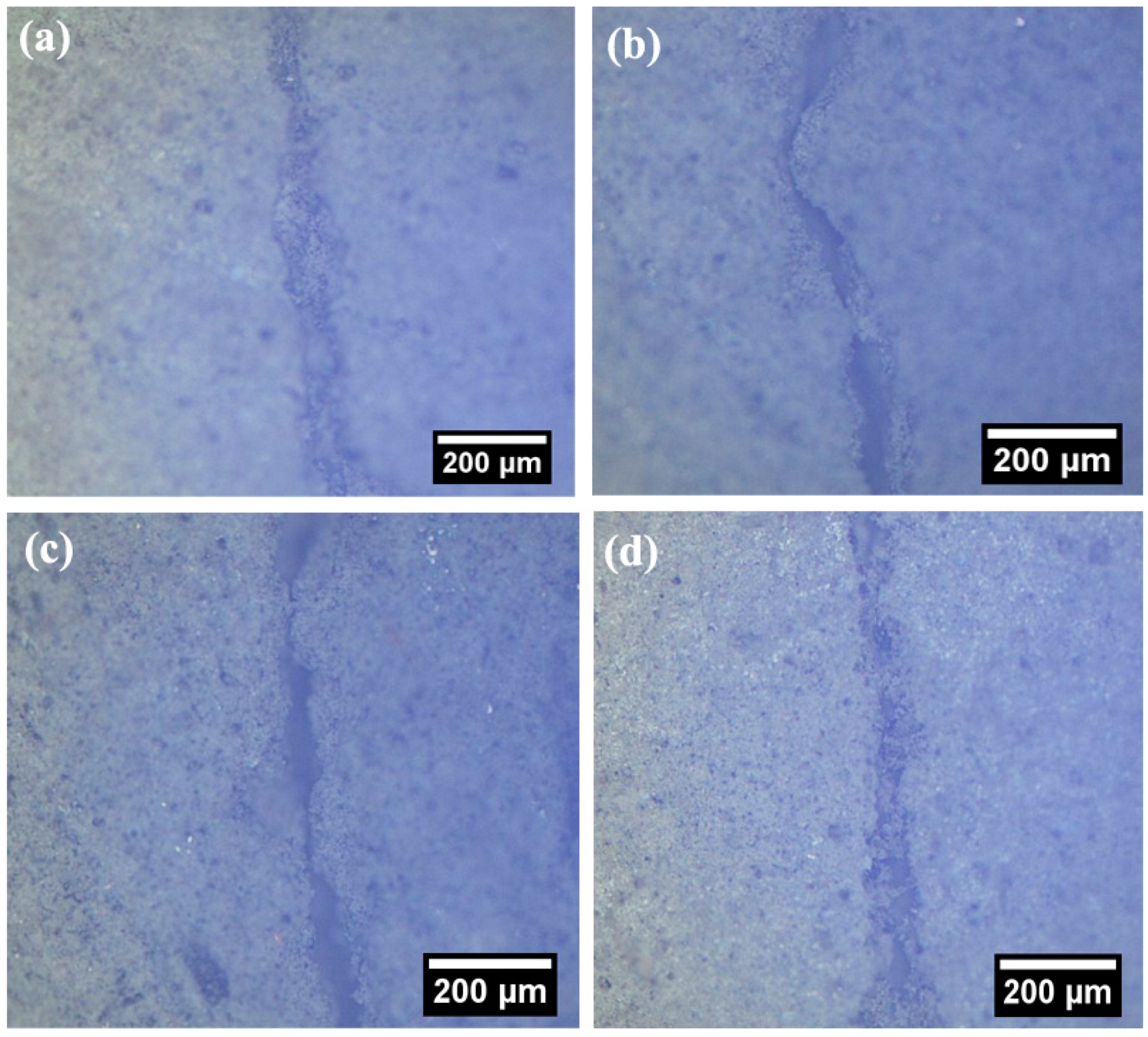
2.5. Water-Flow Test through the Microcracked Specimen
2.6. Investigation on Swelling, Rheological, and Mechanical Properties
3. Results and Discussion
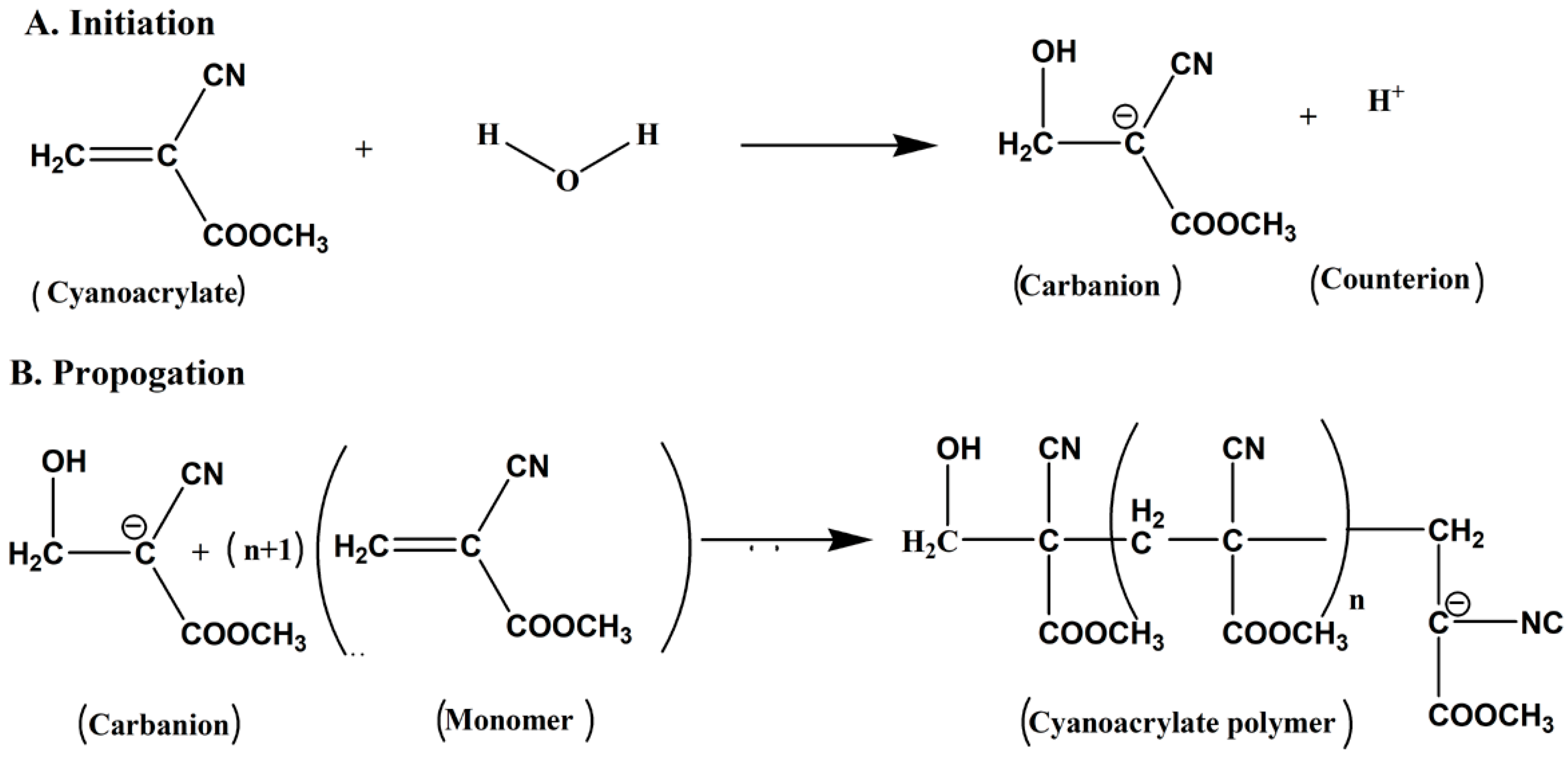
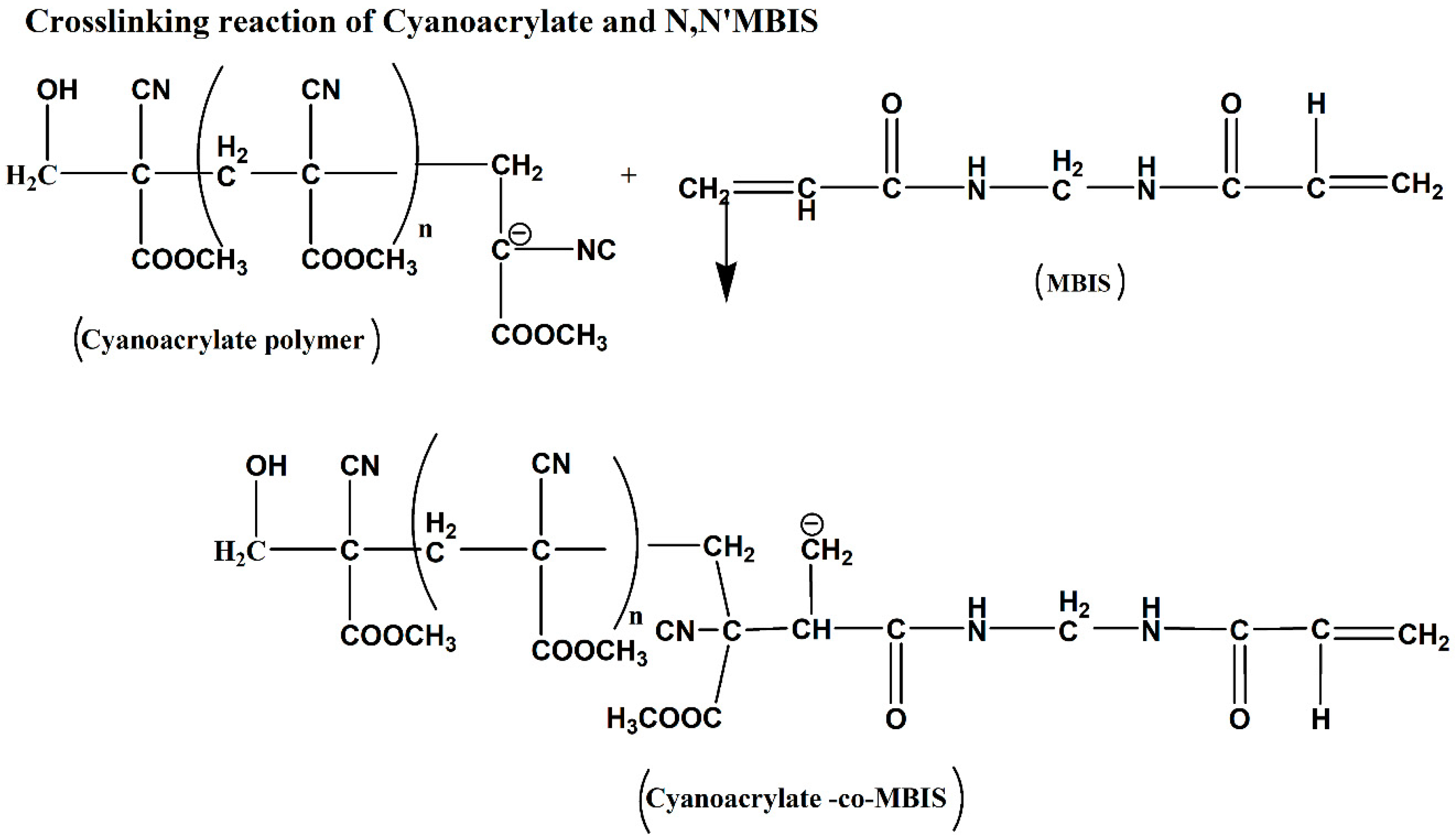
3.1. Polymer Synthesis Mechanism
3.2. Characterization of PAM, SPAM, and DPAM
3.2.1. FTIR Analysis
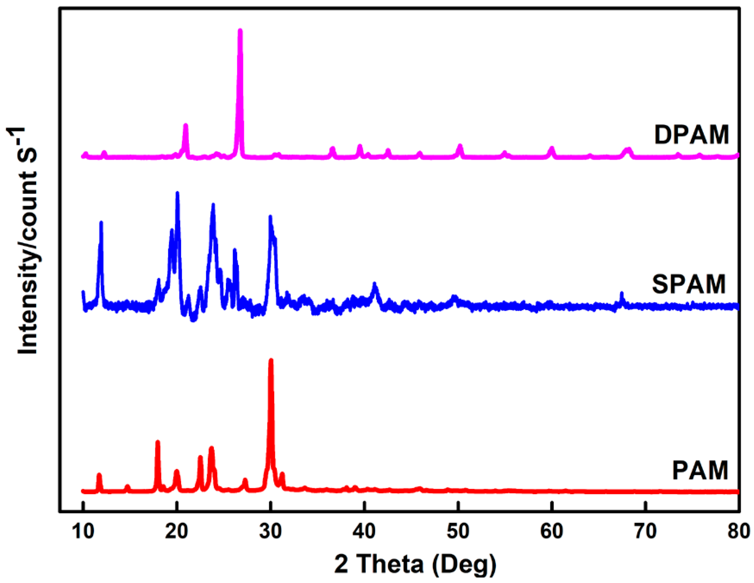
3.2.2. XRD Analysis
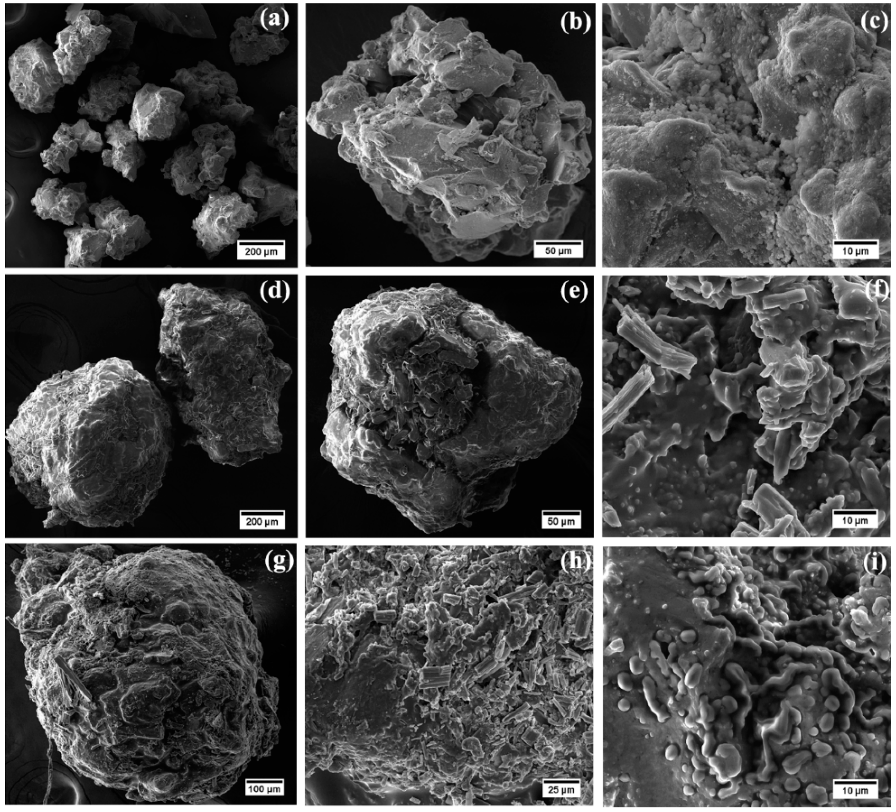
3.2.3. SEM Analysis
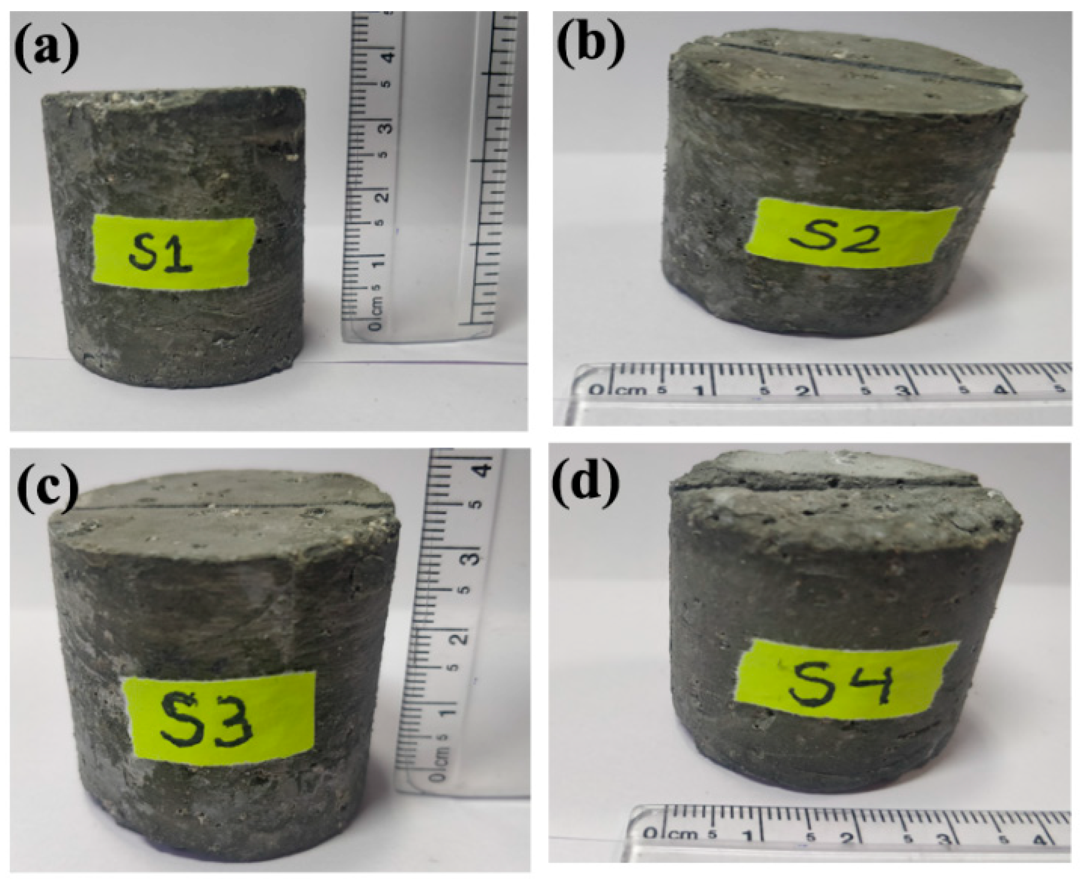
3.3. Characterization of Cement and Cement Core
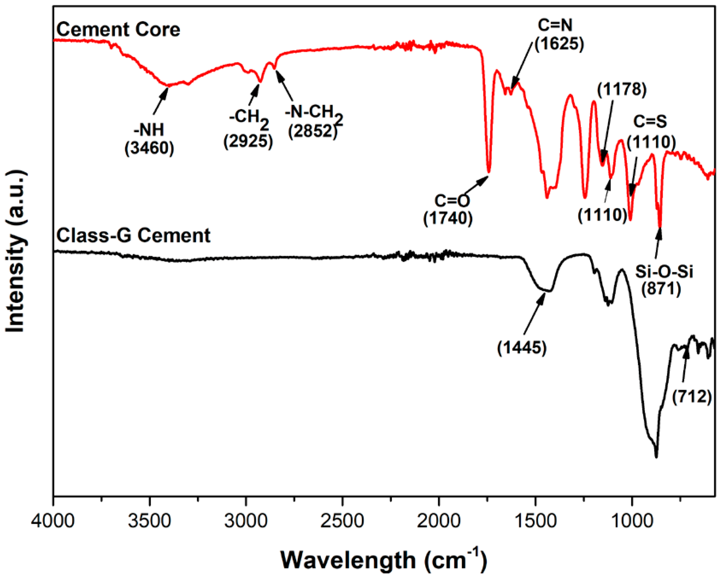
3.3.1. FTIR Analysis
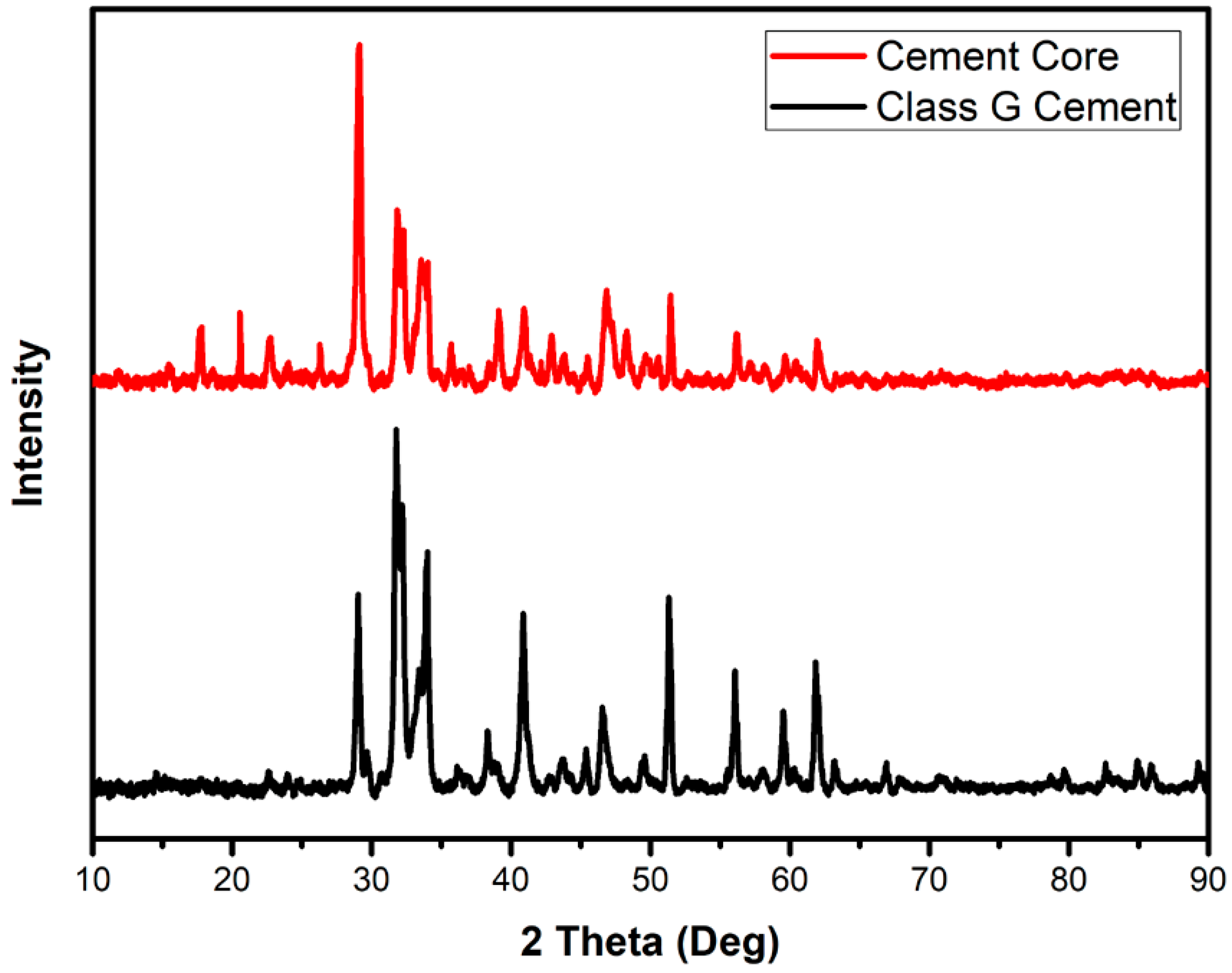
3.3.2. XRD Analysis
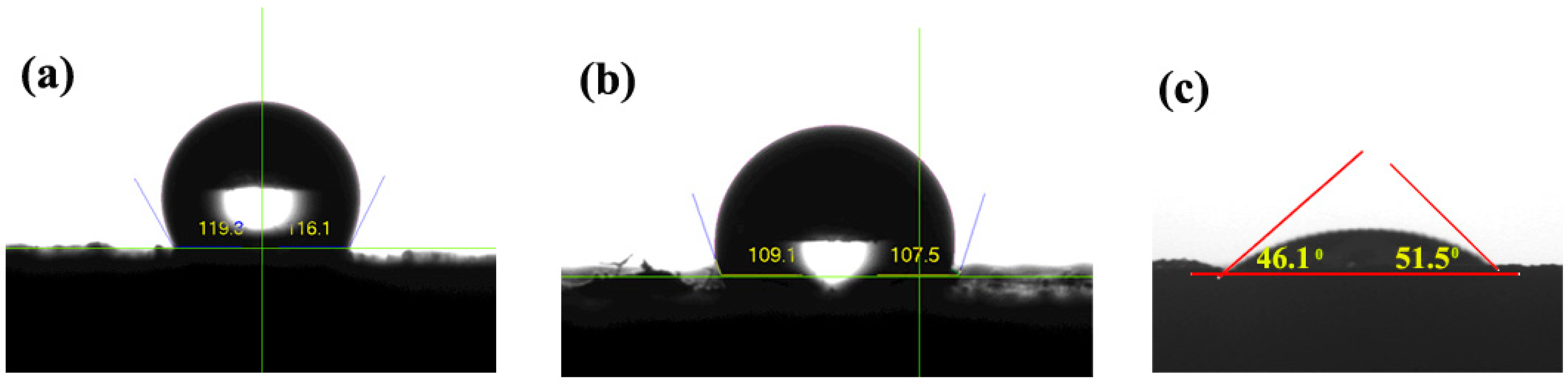
3.3.3. Contact Angle Measurement
3.4. Investigation of Water Absorption of PAM, SPAM, and DPAM
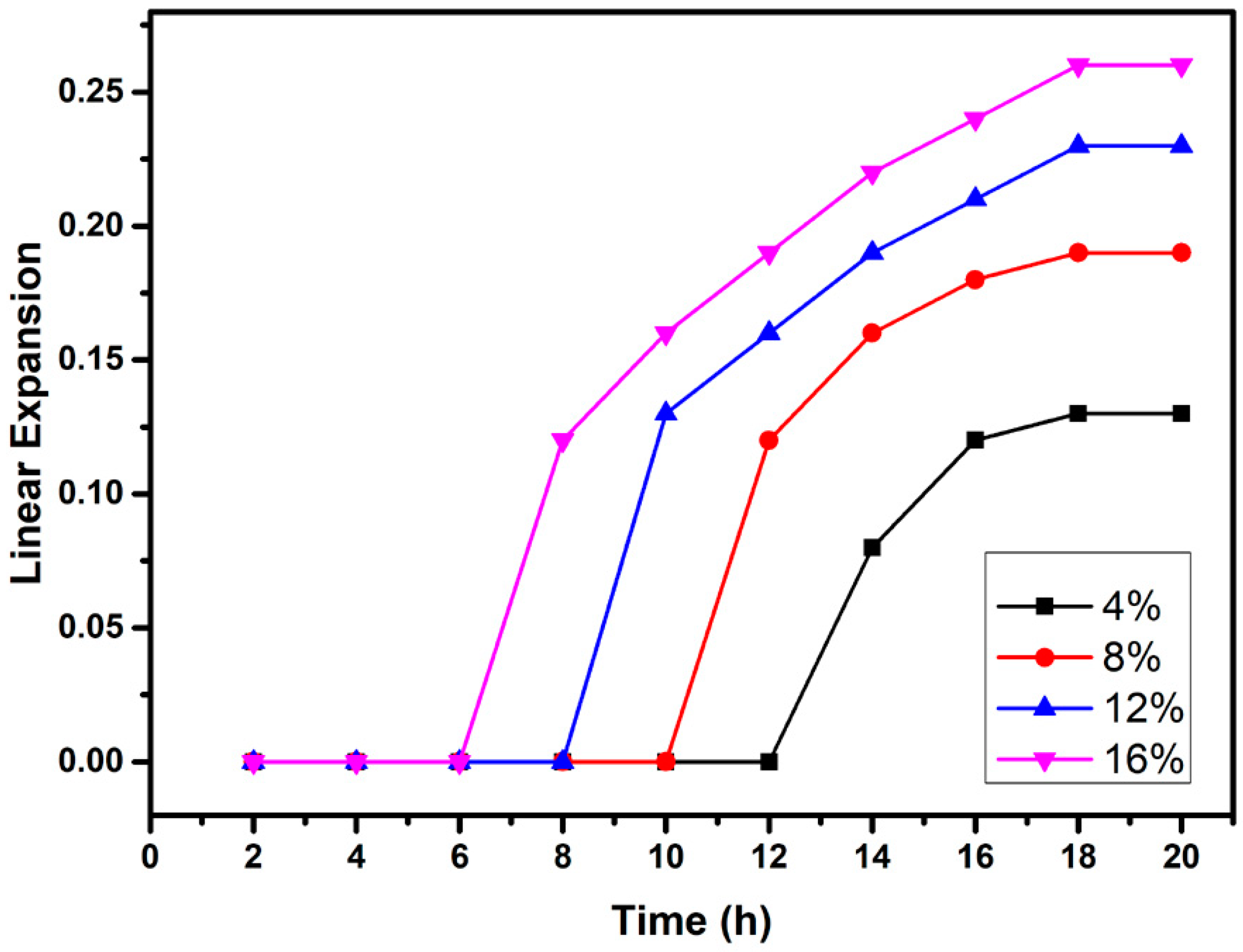
3.5. Linear Expansion
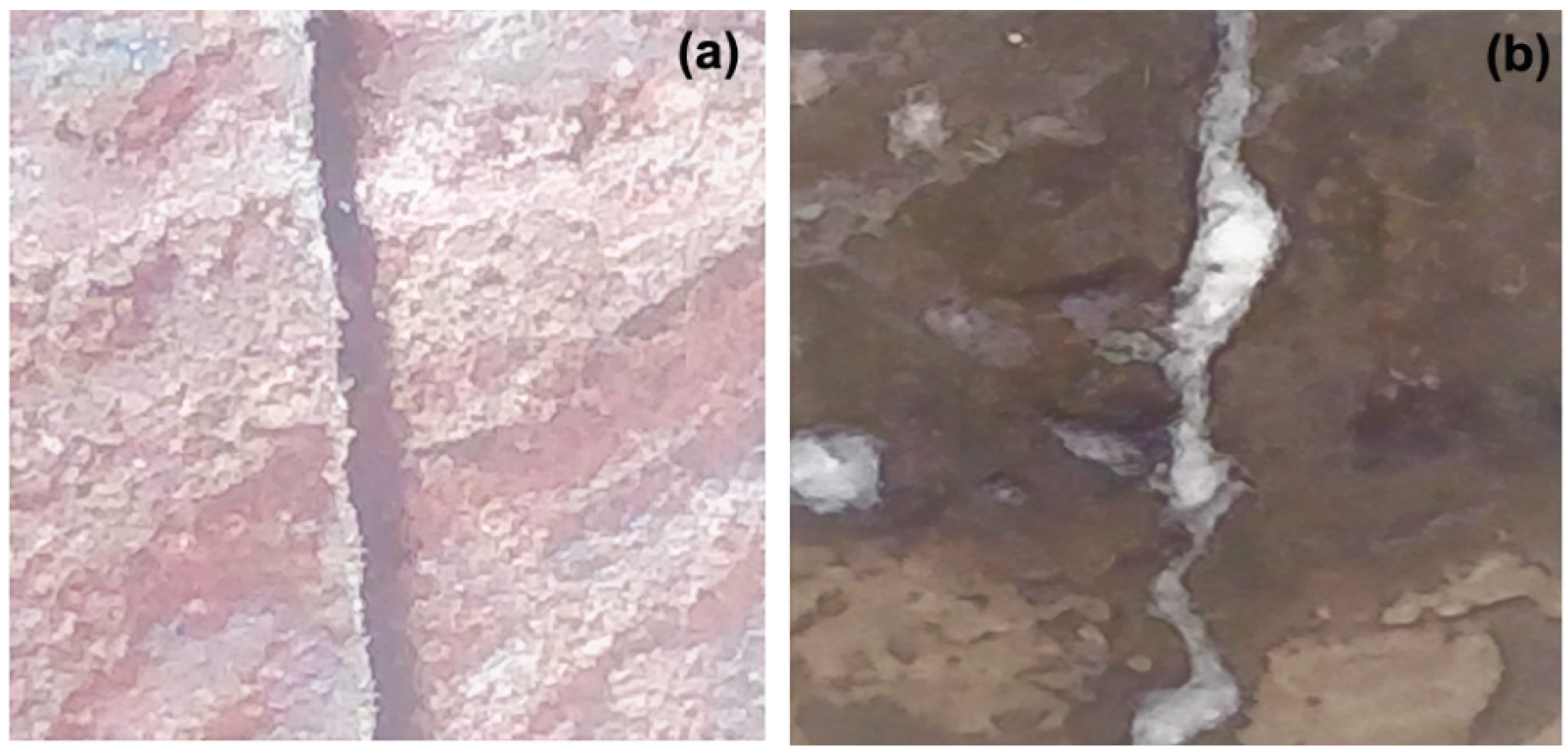
3.6. Water-Flow Measurement
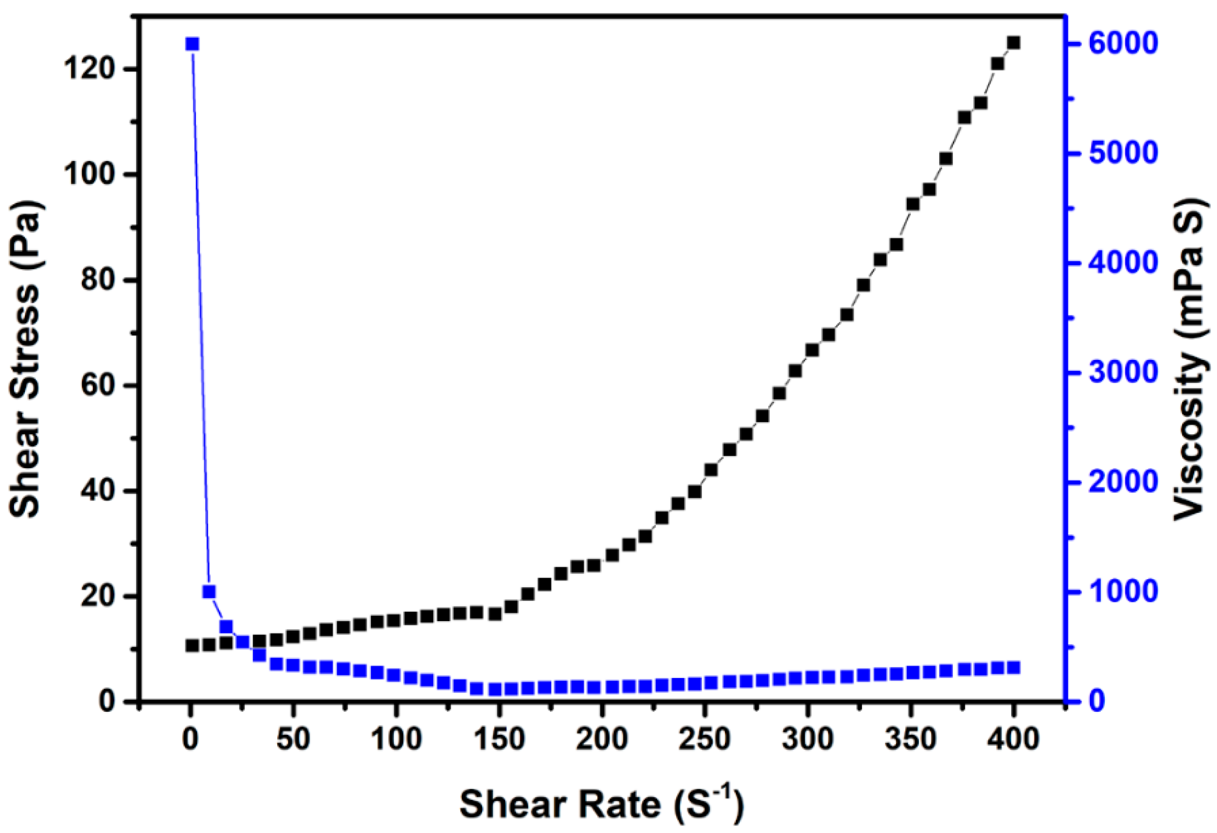
3.7. Rheological Behavior
3.8. Compressive Strength
4. Conclusions
- The synthesized DPAM start absorbing water after 6 h of exposure, thereby increases its stability during cement slurry transportation into the oil well, thus justifies its impregnation in the cement slurry.
- The DPAM absorbs water about 250% of its own weight after 26 h time of exposure. Moreover, it can also absorb water about 40% of its own weight under a maximum oil well salinity of 270,000 ppm.
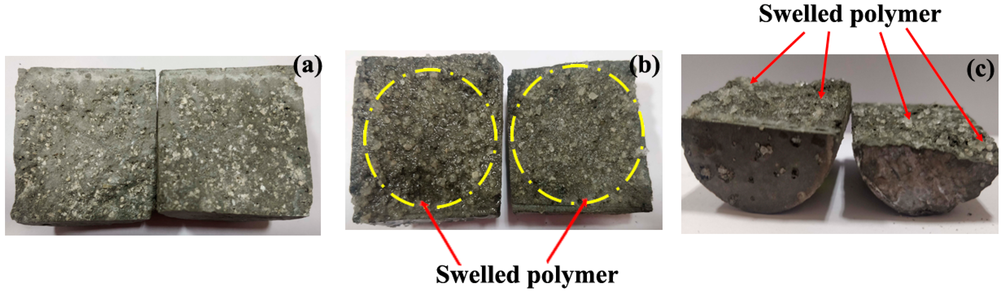
- The synthesized cement core with 16% dosage of DPAM possessed better self-healing capability within 12 h.
- With increase in dosage of DPAM in the cement core the linear expansion increases with a maximum of 0.26 mm/mm.
- The cement core with 4% dosage of DPAM has shown a maximum compressive strength of 21.6 MPa.
Author Contributions
Funding
Acknowledgments
Conflicts of Interest
References
- Bois, A.-P.; Garnier, A.; Rodot, F.; Sain-Marc, J.; Aimard, N. How To Prevent Loss of Zonal Isolation Through a Comprehensive Analysis of Microannulus Formation. SPE Drill. Complet. 2011, 26, 13–31. [Google Scholar] [CrossRef]
- Azenha, M.; Faria, R.; Ferreira, D. Identification of early-age concrete temperatures and strains: Monitoring and numerical simulation. Cem. Concr. Compos. 2009, 31, 369–378. [Google Scholar] [CrossRef]
- Briffaut, M.; Benboudjema, F.; Torrenti, J.M.; Nahas, G. Effects of early-age thermal behaviour on damage risks in massive concrete structures. Eur. J. Environ. Civ. Eng. 2012, 16, 589–605. [Google Scholar] [CrossRef]
- Ghantous, R.M.; Poyet, S.; L’Hostis, V.; Tran, N.C.; François, R. Effect of crack openings on carbonation-induced corrosion. Cem. Concr. Res. 2017, 95, 257–269. [Google Scholar] [CrossRef]
- Levine, D.C.; Thomas, E.W.; Bezner, H.P.; Tolle, G.C. Annular Gas Flow After Cementing: A Look At Practical Solutions. In Proceedings of the SPE Annual Technical Conference and Exhibition, Las Vegas, NV, USA, 23–26 September 1979; Society of Petroleum Engineers: Richardson, TX, USA, 1979. [Google Scholar] [CrossRef]
- Sabins, F.L.; Tinsley, J.M.; Sutton, D.L. Transition Time of Cement Slurries Between the Fluid and Set States. Soc. Pet. Eng. J. 2007, 22, 875–882. [Google Scholar] [CrossRef]
- Bourgoyne, A.T.; Scott, S.L.; Regg, J.B. Sustained Casing Pressure in Offshore Producing Wells. In Proceedings of the Offshore Technology Conference, Houston, TX, USA, 3–6 May 1999. [Google Scholar] [CrossRef]
- Ingraffea, A.R.; Wells, M.T.; Santoro, R.L.; Shonkoff, S.B.C. Assessment and risk analysis of casing and cement impairment in oil and gas wells in Pennsylvania, 2000–2012. Proc. Natl. Acad. Sci. USA 2014, 111, 10955–10960. [Google Scholar] [CrossRef] [Green Version]
- Stone, C.H.; Fleckenstein, W.W.; Eustes, A.W. An Assessment of the Probability of Subsurface Contamination of Aquifers from Oil and Gas Wells in the Wattenberg Field, Modified for Water-Well Location. SPE Prod. Oper. 2018, 34, 001–017. [Google Scholar] [CrossRef]
- Ma, C.; Deng, J.; Wu, R.; Yu, B.; Zhou, Y.; Lin, S. A novel self-healing spacer fluid for sustained casing pressure mitigation. J. Pet. Sci. Eng. 2018, 163, 722–730. [Google Scholar] [CrossRef]
- Liu, H.; Huang, H.; Wu, X.; Peng, H.; Li, Z.; Hu, J.; Yu, Q. Effects of external multi-ions and wet-dry cycles in a marine environment on autogenous self-healing of cracks in cement paste. Cem. Concr. Res. 2019, 120, 198–206. [Google Scholar] [CrossRef]
- Qiu, J.; Ruan, S.; Unluer, C.; Yang, E.H. Autogenous healing of fiber-reinforced reactive magnesia-based tensile strain-hardening composites. Cem. Concr. Res. 2019, 115, 401–413. [Google Scholar] [CrossRef]
- Chen, J.; Ye, G. A Lattice Boltzmann single component model for simulation of the autogenous self-healing caused by further hydration in cementitious material at mesoscale. Cem. Concr. Res. 2019, 123, 105782. [Google Scholar] [CrossRef]
- Granger, S.; Loukili, A.; Pijaudier-cabot, G.; Chanvillard, G. Experimental characterization of the self-healing of cracks in an ultra high performance cementitious material: Mechanical tests and acoustic emission analysis. Cem. Concr. Res. 2007, 37, 519–527. [Google Scholar] [CrossRef] [Green Version]
- Aliko-Benítez, A.; Doblaré, M.; Sanz-Herrera, J.A. Chemical-diffusive modeling of the self-healing behavior in concrete. Int. J. Solids Struct. 2015, 69–70, 392–402. [Google Scholar] [CrossRef]
- Abid, K.; Gholami, R.; Choate, P.; Nagaratnam, B.H. A review on cement degradation under CO2-rich environment of sequestration projects. J. Nat. Gas Sci. Eng. 2015, 27, 1149–1157. [Google Scholar] [CrossRef] [Green Version]
- Lepech, M.D.; Li, V.C. Water permeability of engineered cementitious composites. Cem. Concr. Compos. 2009, 31, 744–753. [Google Scholar] [CrossRef]
- Bhaskar, S.; Anwar, K.M.; Lachemi, M.; Wolfaardt, G.; Otini, M. Effect of self-healing on strength and durability of zeolite-immobilized bacterial cementitious mortar composites. Cem. Concr. Compos. 2017, 82, 23–33. [Google Scholar] [CrossRef]
- Bundur, Z.B.; Amiri, A.; Ersan, Y.C.; Boon, N.; De Belie, N. Impact of air entraining admixtures on biogenic calcium carbonate precipitation and bacterial viability. Cem. Concr. Res. 2017, 98, 44–49. [Google Scholar] [CrossRef]
- Achal, V.; Mukerjee, A.; Sudhakara Reddy, M. Biogenic treatment improves the durability and remediates the cracks of concrete structures. Constr. Build. Mater. 2013, 48, 1–5. [Google Scholar] [CrossRef]
- Ruan, S.; Qiu, J.; Weng, Y.; Yang, Y.; Yang, E.; Chu, J.; Unluer, C. Cement and Concrete Research The use of microbial induced carbonate precipitation in healing cracks within reactive magnesia cement-based blends. Cem. Concr. Res. 2019, 115, 176–188. [Google Scholar] [CrossRef]
- Vijay, K.; Murmu, M.; Deo, S.V. Bacteria based self healing concrete – A review. Constr. Build. Mater. 2017, 152, 1008–1014. [Google Scholar] [CrossRef]
- Han, S.; Choi, E.K.; Park, W.; Yi, C.; Chung, N. Effectiveness of expanded clay as a bacteria carrier for self-healing concrete. Appl. Biol. Chem. 2019, 62, 19. [Google Scholar] [CrossRef]
- Wang, J.Y.; De Belie, N.; Verstraete, W. Diatomaceous earth as a protective vehicle for bacteria applied for self-healing concrete. J. Ind. Microbiol. Biotechnol. 2012, 39, 567–577. [Google Scholar] [CrossRef] [PubMed]
- Belie, N. De Application of modified-alginate encapsulated carbonate producing bacteria in concrete: A promising strategy for crack self-healing. Front. Microbiol. 2015, 6, 1–14. [Google Scholar] [CrossRef] [Green Version]
- Van Tittelboom, K.; De Belie, N. Self-healing in cementitious materials-a review. Materials 2013, 6, 2182–2217. [Google Scholar] [CrossRef] [Green Version]
- Mignon, A.; Snoeck, D.; Dubruel, P.; Van Vlierberghe, S.; De Belie, N. Crack mitigation in concrete: Superabsorbent polymers as key to success? Materials 2017, 10, 237. [Google Scholar] [CrossRef] [Green Version]
- Liu, H.; Bu, Y.; Sanjayan, J.G.; Nazari, A.; Shen, Z. The application of coated superabsorbent polymer in well cement for plugging the microcrack. Constr. Build. Mater. 2016, 104, 72–84. [Google Scholar] [CrossRef]
- Jang, S.-J.; Yun, H.-D.; Kim, S.-W.; Park, W.-S.; Kobayashi, K. Properties of strain-hardening cement composites with superabsorbent polymer particles. Mag. Concr. Res. 2019, 71, 437–448. [Google Scholar] [CrossRef]
- Lee, H. Potential of superabsorbent polymer for self-sealing cracks in concrete. Adv. Appl. Ceram. 2009, 109. [Google Scholar] [CrossRef] [Green Version]
- Snoeck, D.; Steuperaert, S.; Van Tittelboom, K.; Dubruel, P.; De Belie, N. Visualization of water penetration in cementitious materials with superabsorbent polymers by means of neutron radiography. Cem. Concr. Res. 2012, 42, 1113–1121. [Google Scholar] [CrossRef]
- Snoeck, D.; Van Tittelboom, K.; Steuperaert, S.; Dubruel, P.; Belie, N. De Self-healing cementitious materials by the combination of microfibres and superabsorbent polymers. J. Intell. Mater. Syst. Struct. 2014, 25. [Google Scholar] [CrossRef] [Green Version]
- Lee, H.X.D.; Wong, H.S.; Buenfeld, N.R. Self-sealing of cracks in concrete using superabsorbent polymers. Cem. Concr. Res. 2016, 79, 194–208. [Google Scholar] [CrossRef] [Green Version]
- Boughton, L.D.; Pavlich, J.P.; Wahl, W.W. The Use Of Dispersants In Cement Slurries To Improve Placement Techniques. In Proceedings of the Fall Meeting of the Society of Petroleum Engineers of AIME, Los Angeles, CA, USA, 7–8 October 1962; Society of Petroleum Engineers: Richardson, TX, USA, 1962. [Google Scholar] [CrossRef]
- Baloch, H.; Usman, M.; Rizwan, S.A.; Hanif, A. Properties enhancement of super absorbent polymer (SAP) incorporated self-compacting cement pastes modified by nano silica (NS) addition. Constr. Build. Mater. 2019, 203, 18–26. [Google Scholar] [CrossRef]
- Al-Sharrad, M.; Prakash, R.; Trudvang, C.F.; Al-Mai, N.; Hajjeyah, A.A.; Al-Failakawi, A.H. Assuring optimum production and enhanced operational efficiency through transient simulation a case study in north Kuwait jurassic fields. In Proceedings of the SPE Asia Pacific Oil & Gas Conference and Exhibition, Perth, Australia, 25–27 October 2016. [Google Scholar] [CrossRef]
- Baldoni-Andrey, P.; Lesage, N.; Segues, B.; Pedenaud, P.; Dehaene, P.L. Impact of high salinity of produced water on the technical feasibility of biotreatment for E&P onshore applications. In Proceedings of the SPE International Health, Safety & Environment Conference, Abu Dhabi, United Arab Emirates, 2–4 April 2006. [Google Scholar] [CrossRef]
- Yang, J.; Wang, F.; Liu, Z.; Liu, Y.; Hu, S. Early-state water migration characteristics of superabsorbent polymers in cement pastes. Cem. Concr. Res. 2019, 118, 25–37. [Google Scholar] [CrossRef]
- Cavanagh, P.H.; Johnson, C.R.; Le Roy-Delage, S.; DeBruijn, G.G.; Cooper, I.; Guillot, D.J.; Bulte, H.; Dargaud, B. Self-Healing Cement—Novel Technology to Achieve Leak-Free Wells. In Proceedings of the SPE/IADC Drilling Conference, Amsterdam, The Netherlands, 20–22 February 2007. [Google Scholar] [CrossRef]
- Dumitrescu, A.M.; Lisa, G.; Iordan, A.R.; Tudorache, F.; Petrila, I.; Borhan, A.I.; Palamaru, M.N.; Mihailescu, C.; Leontie, L.; Munteanu, C. Ni ferrite highly organized as humidity sensors. Mater. Chem. Phys. 2015, 156, 170–179. [Google Scholar] [CrossRef]
- Sabhapondit, A.; Borthakur, A.; Haque, I. Characterization of acrylamide polymers for enhanced oil recovery. J. Appl. Polym. Sci. 2003, 87, 1869–1878. [Google Scholar] [CrossRef]
- Vinodh, R.; Babu, C.M.; Abidov, A.; Ravikumar, R.; Palanichamy, M.; Choi, E.Y.; Jang, H.T. Synthesis and Characterization of 1-octyl 2-cyano Acrylate for Wound Healing Applications. Int. J. Bio-Sci. Bio-Technol. 2016, 8, 339–350. [Google Scholar] [CrossRef] [Green Version]
- Parmar, K.R.; Dora, D.T.K.; Pant, K.K.; Roy, S. An ultra-light flexible aerogel-based on methane derived CNTs as a reinforcing agent in silica-CMC matrix for efficient oil adsorption. J. Hazard. Mater. 2019, 375, 206–215. [Google Scholar] [CrossRef]
- Liu, H.; Bu, Y.; Sanjayan, J.; Shen, Z. Effects of chitosan treatment on strength and thickening properties of oil well cement. Constr. Build. Mater. 2015, 75, 404–414. [Google Scholar] [CrossRef]
- Trezza, M.A. Hydration study of ordinary portland cement in the presence of zinc ions. Mater. Res. 2007, 10, 331–334. [Google Scholar] [CrossRef]
- Rai, U.S.; Singh, R.K. Effect of polyacrylamide on the different properties of cement and mortar. Mater. Sci. Eng. A 2005, 392, 42–50. [Google Scholar] [CrossRef]
- Law, K.-Y. Definitions for Hydrophilicity, Hydrophobicity, and Superhydrophobicity: Getting the Basics Right. J. Phys. Chem. Lett. 2014, 5, 686–688. [Google Scholar] [CrossRef] [PubMed]
- Lu, Z.; Kong, X.; Yang, R.; Zhang, Y.; Jiang, L.; Wang, Z.; Wang, Q.; Liu, W.; Zeng, M.; Zhou, S.; et al. Oil swellable polymer modified cement paste: Expansion and crack healing upon oil absorption. Constr. Build. Mater. 2016, 114, 98–108. [Google Scholar] [CrossRef]
- Snoeck, D.; Jensen, O.M.; De Belie, N. The influence of superabsorbent polymers on the autogenous shrinkage properties of cement pastes with supplementary cementitious materials. Cem. Concr. Res. 2015, 74, 59–67. [Google Scholar] [CrossRef]
- Snoeck, D.; Van den Heede, P.; Van Mullem, T.; De Belie, N. Water penetration through cracks in self-healing cementitious materials with superabsorbent polymers studied by neutron radiography. Cem. Concr. Res. 2018, 113, 86–98. [Google Scholar] [CrossRef]
- Sugama, T.; Pyatina, T. Self-healing, re-adhering, and carbon-steel corrosion mitigating properties of fly ash-containing calcium aluminum phosphate cement composite at 300 °C hydrothermal temperature. Cem. Concr. Compos. 2019, 99, 1–16. [Google Scholar] [CrossRef]
- Lv, L.; Guo, P.; Liu, G.; Han, N.; Xing, F. Light induced self-healing in concrete using novel cementitious capsules containing UV curable adhesive. Cem. Concr. Compos. 2020, 105, 103445. [Google Scholar] [CrossRef]


| Components | SiO2 | CaO | Fe2O3 | Al2O3 | SO3 | MgO | K2O | Na2O | Other |
|---|---|---|---|---|---|---|---|---|---|
| (wt.%) | 22.84 | 63.72 | 5.02 | 3.46 | 1.69 | 1.30 | 0.46 | 0.89 | 22.84 |
| Sl. No. | Specimen No. | Weight of Cement (g) | DPAM (wt.%) | DO 65 (wt.%) | Water (wt.%) |
|---|---|---|---|---|---|
| 1 | S1 | 500 | 4 | 0.2 | 44 |
| 2 | S2 | 500 | 8 | 0.2 | 44 |
| 3 | S3 | 500 | 12 | 0.2 | 44 |
| 4 | S4 | 500 | 16 | 0.2 | 44 |
| 5 | Neat Cement (NC) | 500 | 0 | 0.2 | 44 |
| Sl. No. | Type of Cement and Additives | Water-Absorption Capacity of Polymer (G/g) | Linear Expansion of Cement (µm/m) | Compressive Strength (MPa) | Reference |
|---|---|---|---|---|---|
| 1 | Class-G Oil well cement, SAP, Calcium carbonate | 12.5 (within 35 min) | Not studied | 24.4 | Liu et al. [23] |
| 2 | Cement, SAP | 163 | 100–200 | Not studied | Snoeck et al. [49] |
| 3 | Cement with fly ash, SAP | 2.59 | 20 | 10.6 | Lee et al. [33] |
| 4 | Cement, Fly ash, SAP | 8 (after 2 h) | Not studied | 15 | Snoeck et al. [50] |
| 5 | SAP, poly-carboxylate ether, ordinary Portland cement | 27.5 (within 15 min) | 100 | 54 | Baloch et al. [35] |
| 6 | Cement, chitosen, PAM, Class-G oil well cement | 4.8 (within 5 h) | Not studied | 38–41 | Liu et al. [44] |
| 7 | Portland Cement, 5%SAP | 0.08 | Not studied | 28.74 Mpa | Rai and Singh [46] |
| 8 | Class F Fly ash, CAC, sodium hexametaphosphate | Not studied | 180 | 25 | Sugama and Pyatina [51] |
| 9 | Epoxy acrylate, OPC, Cellulose | Not studied | 900 | 7 (Flexural strength) | Lv et al. [52] |
| 10 | Class-G oil-well cement, DPAM | 2.5 (after 26 h) | 260 | 21.6 | Present work |
© 2020 by the authors. Licensee MDPI, Basel, Switzerland. This article is an open access article distributed under the terms and conditions of the Creative Commons Attribution (CC BY) license (http://creativecommons.org/licenses/by/4.0/).
Share and Cite
Richhariya, G.; Dora, D.T.K.; Parmar, K.R.; Pant, K.K.; Singhal, N.; Lal, K.; Kundu, P.P. Development of Self-Healing Cement Slurry through the Incorporation of Dual-Encapsulated Polyacrylamide for the Prevention of Water Ingress in Oil Well. Materials 2020, 13, 2921. https://doi.org/10.3390/ma13132921
Richhariya G, Dora DTK, Parmar KR, Pant KK, Singhal N, Lal K, Kundu PP. Development of Self-Healing Cement Slurry through the Incorporation of Dual-Encapsulated Polyacrylamide for the Prevention of Water Ingress in Oil Well. Materials. 2020; 13(13):2921. https://doi.org/10.3390/ma13132921
Chicago/Turabian StyleRichhariya, G., D.T.K. Dora, K.R. Parmar, K.K. Pant, N. Singhal, K. Lal, and P.P. Kundu. 2020. "Development of Self-Healing Cement Slurry through the Incorporation of Dual-Encapsulated Polyacrylamide for the Prevention of Water Ingress in Oil Well" Materials 13, no. 13: 2921. https://doi.org/10.3390/ma13132921
APA StyleRichhariya, G., Dora, D. T. K., Parmar, K. R., Pant, K. K., Singhal, N., Lal, K., & Kundu, P. P. (2020). Development of Self-Healing Cement Slurry through the Incorporation of Dual-Encapsulated Polyacrylamide for the Prevention of Water Ingress in Oil Well. Materials, 13(13), 2921. https://doi.org/10.3390/ma13132921