Study on Strength and Stiffness of WC-Co-NiCr Graded Samples

Abstract
1. Introduction
2. Preparation of Samples
3. Methods of Material Properties and Composition
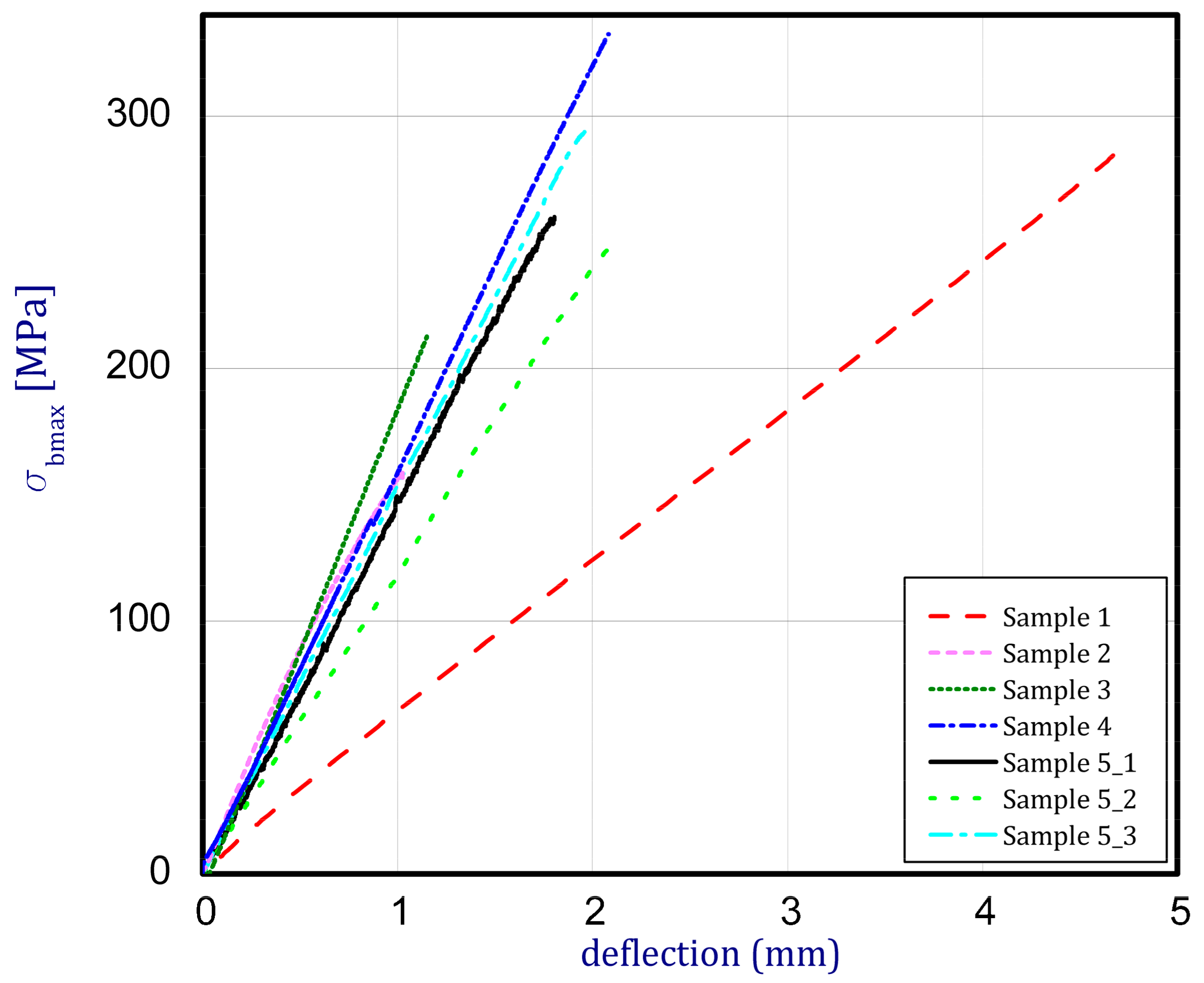
3.1. Bending Test
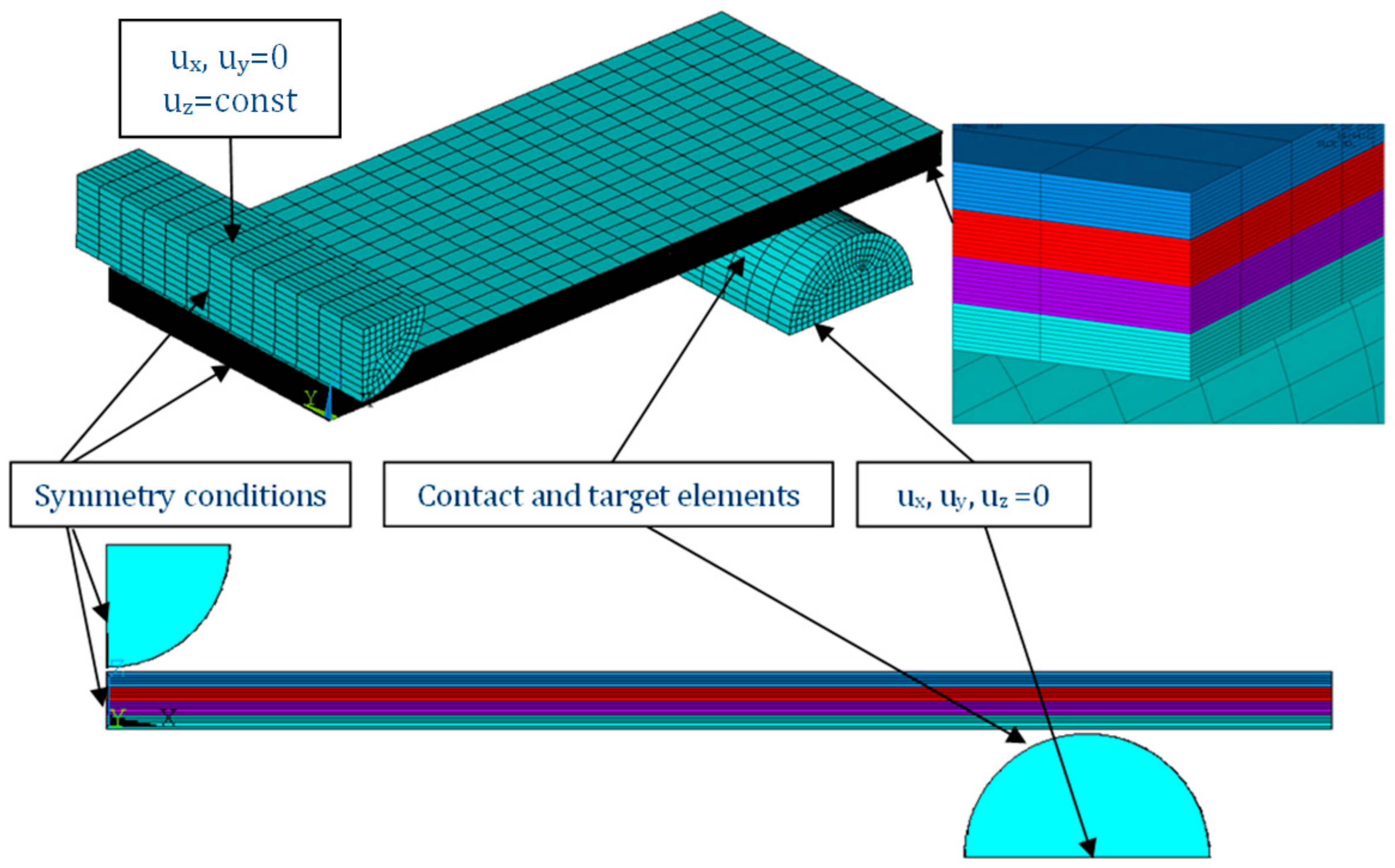
3.2. FE Analysis
3.3. Microscopic Examinations
3.4. Indentation Method
4. Results
4.1. Bending Test
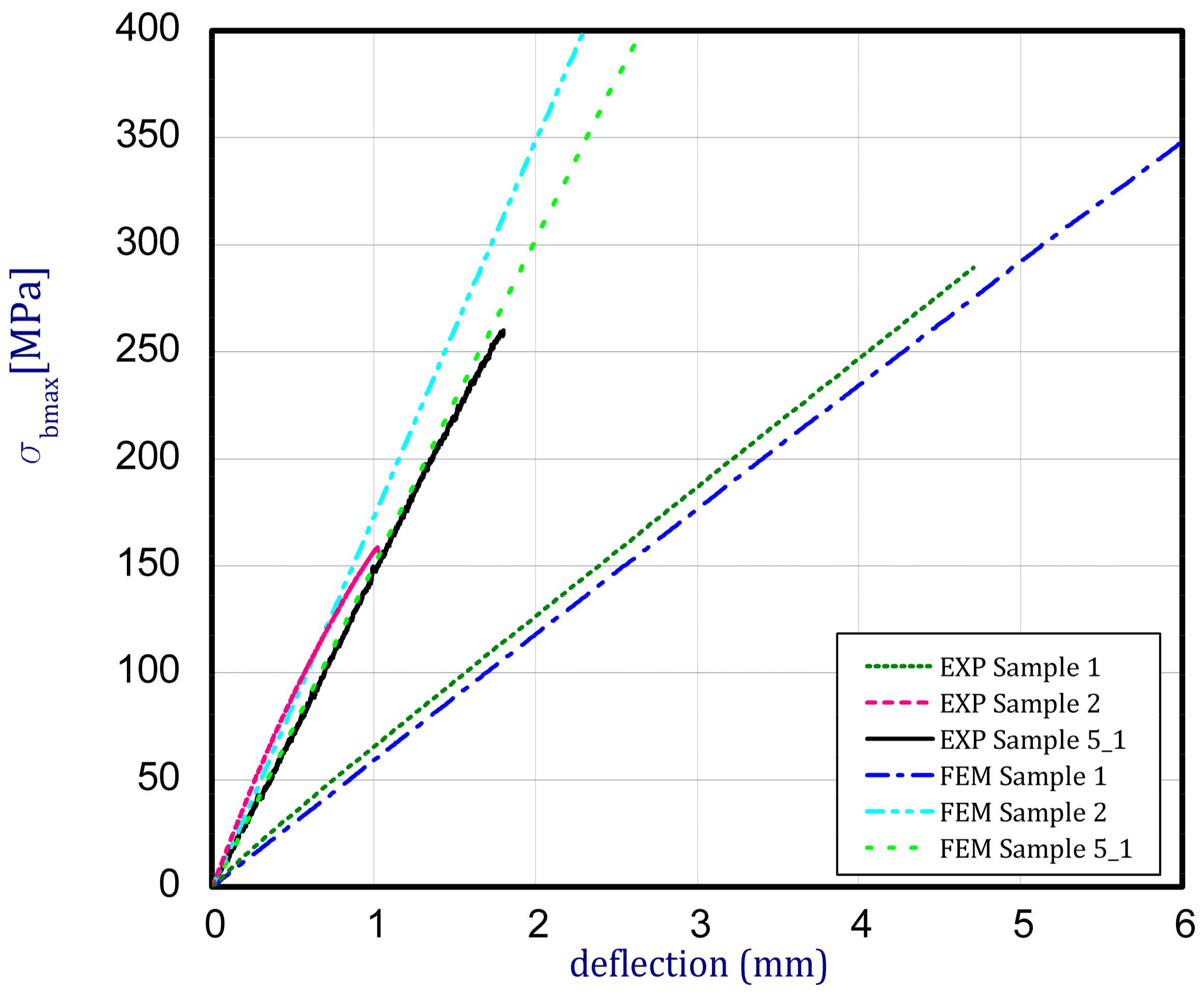
4.2. Validation of FE Model
4.3. Microscopic Examinations
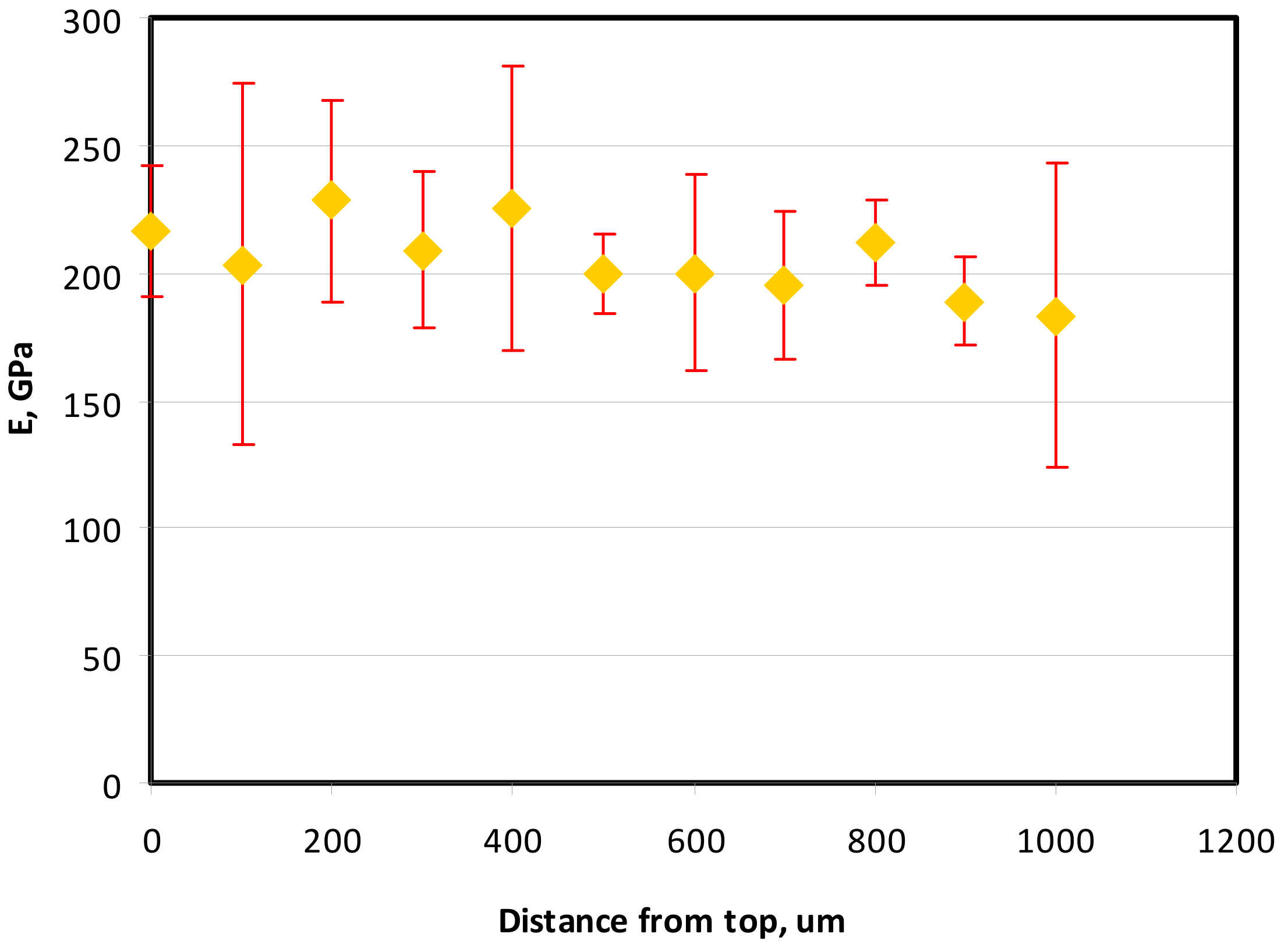
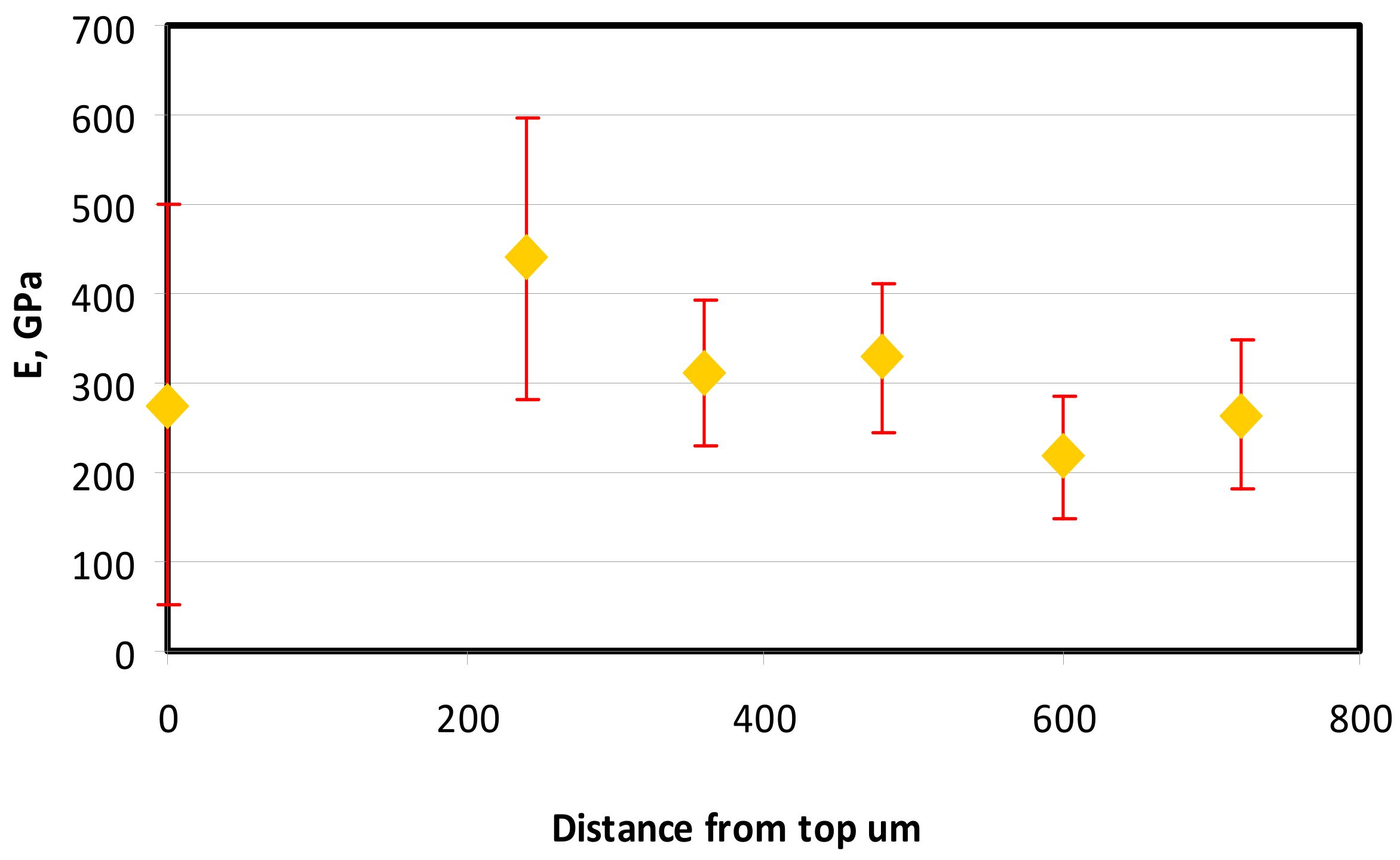
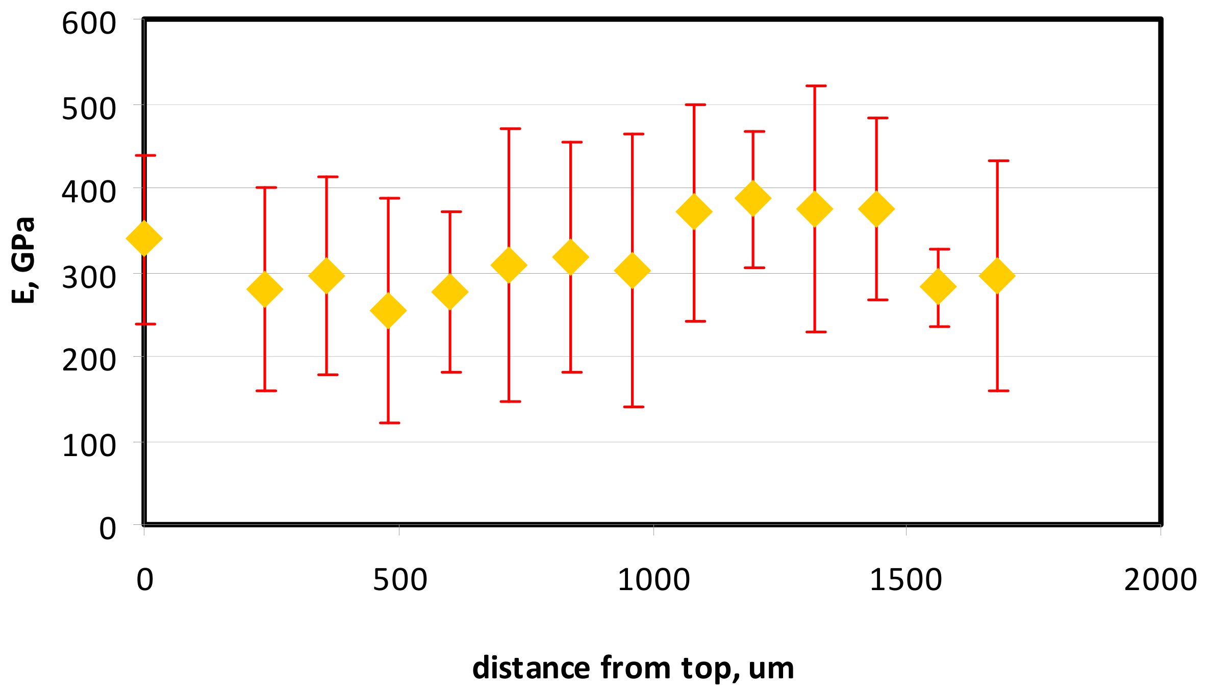
4.4. Indentation Results
5. Summary
- the employed method of manufacturing multi-layer thin-walled samples enables building a functionally graded material by the use of different components and elements;
- Young’s moduli measured during bending tests differ from those measured by the indentation technique;
- based on the obtained results, real material properties and distributions should be verified depending on method, obtained thicknesses of layers and composition;
- the method of indentation can be employed to give some results of elasticity but cannot be used as a basic test in determining total material properties;
- the paper includes preliminary investigation on thin-walled FGM samples from the point of a proposed technique as a detonation gun layer deposition method and applied constituents comprising a structure of FGM. It should be underlined that the present method can be further developed with consideration of other compositions and a greater number of layers.
Funding
Acknowledgments
Conflicts of Interest
References
- Koizumi, M. FGM activities in Japan. Compos. Part B 1997, 28, 1–4. [Google Scholar] [CrossRef]
- Koizumi, M.; Niino, M. Overview of FGM Research in Japan. MRS Bull. 1995, 20, 19–21. [Google Scholar] [CrossRef]
- Sasaki, M.; Wang, Y.; Hirano, T.; Hirai, T. Design of SiC/C functionally gradient material and its preparation by chemical vapor deposition. J. Ceram. Soc. Jpn. 1989, 97, 539–543. [Google Scholar] [CrossRef][Green Version]
- Kayser, W.A.; Ilschner, B. FGM research activities in Europe. MRS Bull. 1995, 20, 22–26. [Google Scholar] [CrossRef]
- Huang, X.L.; Shen, H.S. Nonlinear vibration and dynamic response of functionally graded plates in thermal environments. Int. J. Solids Struct. 2004, 41, 2403–2427. [Google Scholar] [CrossRef]
- Wattanasakulpong, N.; Prusty, G.B.; Kelly, D.W. Thermal buckling and elastic vibration of third-order shear deformable functionally graded beams. Int. J. Mech. Sci. 2011, 53, 734–743. [Google Scholar] [CrossRef]
- Shi, G. A new simple third-order shear deformation theory of plates. Int. J. Solids Struct. 2007, 44, 4399–4417. [Google Scholar] [CrossRef]
- Yang, J.; Shen, H.S. Nonlinear bending analysis of shear deformable functionally graded plates subjected to thermo-mechanical loads under various boundary conditions. Compos. Part B Eng. 2003, 34, 103–115. [Google Scholar] [CrossRef]
- Samsam Shariat, B.A.; Eslami, M.R. Thermal buckling of imperfect functionally graded plates. Int. J. Solids Struct. 2006, 43, 4082–4096. [Google Scholar] [CrossRef]
- Yin, S.H.; Hale, J.S.; Yu, T.T.; Bui, Q.T.; Bordas, S.P.A. Isogeometric locking-free plate element: A simple first order shear deformation theory for functionally graded plates. Compos. Struct. 2015, 118, 121–138. [Google Scholar] [CrossRef]
- Bhardwaj, G.; Singh, I.V.; Mishra, B.K.; Bui, Q.T. Numerical simulation of functionally graded cracked plates using NURBS based XIGA under different loads and boundary conditions. Compos. Struct. 2015, 126, 347–359. [Google Scholar] [CrossRef]
- Czechowski, L.; Kowal-Michalska, K. Static and dynamic buckling of rectangular functionally graded plates subjected to thermal loading. Strength Mater. 2013, 45, 666–673. [Google Scholar] [CrossRef]
- Kolakowski, Z.; Mania, R.J. Dynamic response of thin FG plates with a static unsymmetrical stable postbuckling path. Thin Walled Struct. 2015, 86, 10–17. [Google Scholar] [CrossRef]
- Kołakowski, Z.; Teter, A. Static interactive buckling of functionally graded columns with closed cross-sections subjected to axial compression. Compos. Struct. 2015, 123, 257–262. [Google Scholar] [CrossRef]
- Kołakowski, Z.; Teter, A. Load carrying capacity of functionally graded columns with open cross-sections under static compression. Compos. Struct. 2015, 129, 1–7. [Google Scholar] [CrossRef]
- Czechowski, L. Analysis of dynamic response of functionally graded plate due to temperature pulse load. Compos. Struct. 2017, 160, 625–634. [Google Scholar] [CrossRef]
- Bui, T.Q.; Do, T.V.; Ton, L.H.T.; Doan, D.H.; Tanaka, D.H.S.; Pham, D.T.; Nguyen-Van, T.-A.; Yu, T.; Hirose, S. On the high temperature mechanical behaviors analysis of heated functionally graded plates using FEM and a new third-order shear deformation plate theory. Compos. Part B 2016, 92, 218–224. [Google Scholar] [CrossRef]
- Praveen, G.N.; Reddy, J.N. Nonlinear transient thermal elastic analysis of functionally graded ceramic-metal plates. Int. J. Solid Struct. 1998, 35, 4457–4476. [Google Scholar] [CrossRef]
- Show, B.K.; Veerababu, R.; Balamuralikrishnan, R.; Malakondaiah, G. Effect of vanadium and titanium modification on the microstructure and mechanical properties of a microalloyed HSLA steel. Mater. Sci. Eng. 2010, A527, 1595–1604. [Google Scholar] [CrossRef]
- Yu, W.; Qian, Y.J.; Wu, H.B.; Yang, Y.H. Effect of heat treatment process on properties of 1000 MPa ultra-high strength steel. J. Iron Steel Res. Int. 2011, 18, 64–69. [Google Scholar] [CrossRef]
- Rubio, W.M.; Paulino, G.H.; Silva, E.C.N. Analysis, manufacture and characterization of Ni/Cu functionally graded structures. Mater. Des. 2012, 41, 255–265. [Google Scholar] [CrossRef]
- Hangai, Y.; Morita, T.; Utsunomiya, T. Functionally graded aluminum foam consisting of dissimilar aluminum alloys fabricated by sintering and dissolution process. Mater. Sci. Eng. 2017, A696, 544–551. [Google Scholar] [CrossRef]
- Naebe, M.; Shirvanimoghaddam, K. Functionally graded materials: A review of fabrication and properties. Appl. Mater. Today 2016, 5, 223–245. [Google Scholar] [CrossRef]
- Liu, H.; Wang, Z.; Wang, Y.; Li, H. Effect of technological parameters on the process performance of pure Al2O3 layer of Ni–Al2O3 FGMs by self-induced EDM. Int. J. Adv. Manuf. Technol. 2017, 90, 3633–3641. [Google Scholar] [CrossRef]
- Radhika, N.; Kamireddy, T.; Rahul, K.; Shivashankar, A. Fabrication of Cu-Sn-Ni /SiC FGM for Automotive Applications: Investigation of its Mechanical and Tribological Properties. Silicon 2018, 10, 1705–1716. [Google Scholar]
- Matejíceka, J.; Boldyryevaa, H.; Brozek, V.; Sachr, P.; Chráska, T.; Pala, Z. W–steel and W–WC–steel composites and FGMs produced by hotpressing. Fusion Eng. Des. 2015, 100, 364–370. [Google Scholar] [CrossRef]
- Sun, J.; Zhao, J.; Chen, M.; Wang, X.; Zhong, X.; Hou, G. Determination of microstructure and mechanical properties of functionally graded WC-TiC-Al2O3-GNPs micro-nano composite tool materials via two step sintering. Ceram. Int. 2017, 43, 9276–9284. [Google Scholar] [CrossRef]
- Morin, C.; LeGallet, S.; Ariane, M.; Bernard, F. Spark Plasma Sintering tool design for preparing alumina-based Functionally Graded Materials. Ceram. Int. 2016, 42, 3056–3063. [Google Scholar] [CrossRef]
- Cai, Y.; Cheng, Y.; Yin, H.; Yin, X.; Tian, Y.; Chen, J.; Wang, N. Preparation and mechanical properties of Ti3SiC2/SiC functionally graded materials. Ceram. Int. 2017, 43, 6648–6658. [Google Scholar] [CrossRef]
- Martínez-Pañeda, E. On the Finite Element Implementation of Functionally Graded Materials. Materials 2019, 12, 287. [Google Scholar] [CrossRef]
- Senderowski, C.; Bojar, Z. Gas detonation spray forming of Fe-Al coatings in the presence of interlayer. Surf. Coat. Technol. 2008, 202, 3538–3548. [Google Scholar] [CrossRef]
- Senderowski, C.; Bojar, Z.; Wołczyński, W.; Pawłowski, A. Microstructure characterization of D-gun sprayed Fe-Al intermetallic coatings. Intermetallics 2010, 18, 1405–1409. [Google Scholar] [CrossRef]
- Talak, T.L.; Yakovleva, M.S.; Astakhov, E.A.; Letsko, A.I. Structure and properties of detonation gun sprayed coatings from the synthesized FeAlSi/Al2O3 powder. Surf. Coat. Technol. 2018, 353, 93–104. [Google Scholar] [CrossRef]
- Ke, P.L.; Wu, Y.N.; Wang, Q.M.; Gong, J.; Sun, C.; Wen, L.S. Study on thermal barrier coatings deposited by detonation gun spraying. Surf. Coat. Technol. 2005, 208, 2271–2276. [Google Scholar] [CrossRef]
- Saravanan, P.; Selvarajan, V.; Rao, D.S.; Joshi, S.V.; Sundararajan, G. Influence of process variables on the quality of detonation gun sprayed alumina coatings. Surf. Coat. Technol. 2000, 123, 44–54. [Google Scholar] [CrossRef]
- ISO. European Standard PN-EN ISO 7438:2016-03, Metallic Materials—Bending Test; ISO: Geneva, Switzerland, 2016. [Google Scholar]
- User’s Guide ANSYS® 18.2. Available online: http://www.pmt.usp.br/academic/martoran/notasmodelosgrad/ANSYS%20Fluent%20Users%20Guide.pdf (accessed on 16 November 2019).
- Pharr, G.M.; Oliver, W.C.; Brotzen, F.R. On the generality of the relationship among contact stiffness, contact area, and elastic modulus during indentation. J. Mater. Res. 1992, 7, 613–617. [Google Scholar] [CrossRef]
- Kumar, A.; Jayakumar, T.; Raj, B.; Ray, K.K. Correlation between ultrasonic shear wave velocity and Poisson’s ratio for isotropic solid materials. Acta Mater. 2003, 51, 2417–2426. [Google Scholar] [CrossRef]


| Sample 1 | Sample 2 | Sample 3 | Sample 4 | Sample 5_1 (From Left) Sample 5_2 Sample 5_3 | |
|---|---|---|---|---|---|
| View of samples |  |  |  |  |  |
| Composition of main constituents | 100% NiCr | 100% WC–Co | 50% NiCr 50% WC–Co | 75% NiCr 25%WC-Co | Multilayer material (FGM): 1st layer—100% NiCr 2nd layer—25% WC–Co —75% NiCr 3rd layer—75% WC–Co —25% NiCr 4th layer—100% WC–Co |
| Dimensions: thickness (mm) width (mm) length (mm) | 1.2 19.2 120 | 2.0 19.6 122 | 1.6 20.0 121 | 2.35 19.8 125 | 2.1–2.3 mm (each layer circa 0.525–0.575 mm) 19.1–20.0 112.2–120 |
| Number of Sample | Maximum Bending Force (N) | Young’s Modulus (GPa) | Ultimate Strength in Bending (MPa) |
|---|---|---|---|
| Sample 1 | 66.7 | 51.2 | 289.5 |
| Sample 2 | 103.8 | 93.0 | 156.5 |
| Sample 3 | 150.5 | 75.0 | 213.9 |
| Sample 4 | 302.4 | 70.0 | 332.6 |
| Sample 5_1 | 230.2 | 72.0 | 260.1 |
| Sample 5_2 | 172.7 | 59.5 | 248.0 |
| Sample 5_3 | 219.3 | 77.1 | 292.0 |
| Number of Sample | Young’s Modulus (GPa) | Poisson’s Ratio [39] (MPa) |
|---|---|---|
| Sample 1 | 50 | 0.3 |
| Sample 2 | 90 | 0.25 |
| Sample 5_1 | 1st layer—50 | 0.3 |
| 2nd layer—70 | 0.27 | |
| 3rd layer—80 | 0.28 | |
| 4th layer—90 | 0.25 |
 |  Average content of elements (from 14 points): Ni—40.5% C—35.2% Cr—14.4% Others—9.9% |  |
 |  | |
 |  |
 |  Average content of elements (from 11 points): C—72.4% W—18.3% Co—8.5% Others—0.8% |  |
 |  | |
 |  |
 |  Content of elements (from 23 points): Ni—0–90.8% C—8–35.2% Cr—0.4–5% Others—9.9% C—72.4% W—0–89.3% Co—8.5% Others—0.8% |  |
 |  | |
 |  |
© 2019 by the author. Licensee MDPI, Basel, Switzerland. This article is an open access article distributed under the terms and conditions of the Creative Commons Attribution (CC BY) license (http://creativecommons.org/licenses/by/4.0/).
Share and Cite
Czechowski, L. Study on Strength and Stiffness of WC-Co-NiCr Graded Samples. Materials 2019, 12, 4166. https://doi.org/10.3390/ma12244166
Czechowski L. Study on Strength and Stiffness of WC-Co-NiCr Graded Samples. Materials. 2019; 12(24):4166. https://doi.org/10.3390/ma12244166
Chicago/Turabian StyleCzechowski, Leszek. 2019. "Study on Strength and Stiffness of WC-Co-NiCr Graded Samples" Materials 12, no. 24: 4166. https://doi.org/10.3390/ma12244166
APA StyleCzechowski, L. (2019). Study on Strength and Stiffness of WC-Co-NiCr Graded Samples. Materials, 12(24), 4166. https://doi.org/10.3390/ma12244166