The Martensitic Transformation and Mechanical Properties of Ti6Al4V Prepared via Selective Laser Melting

 , ,
, ,  ,
,  and
and
Abstract
1. Introduction
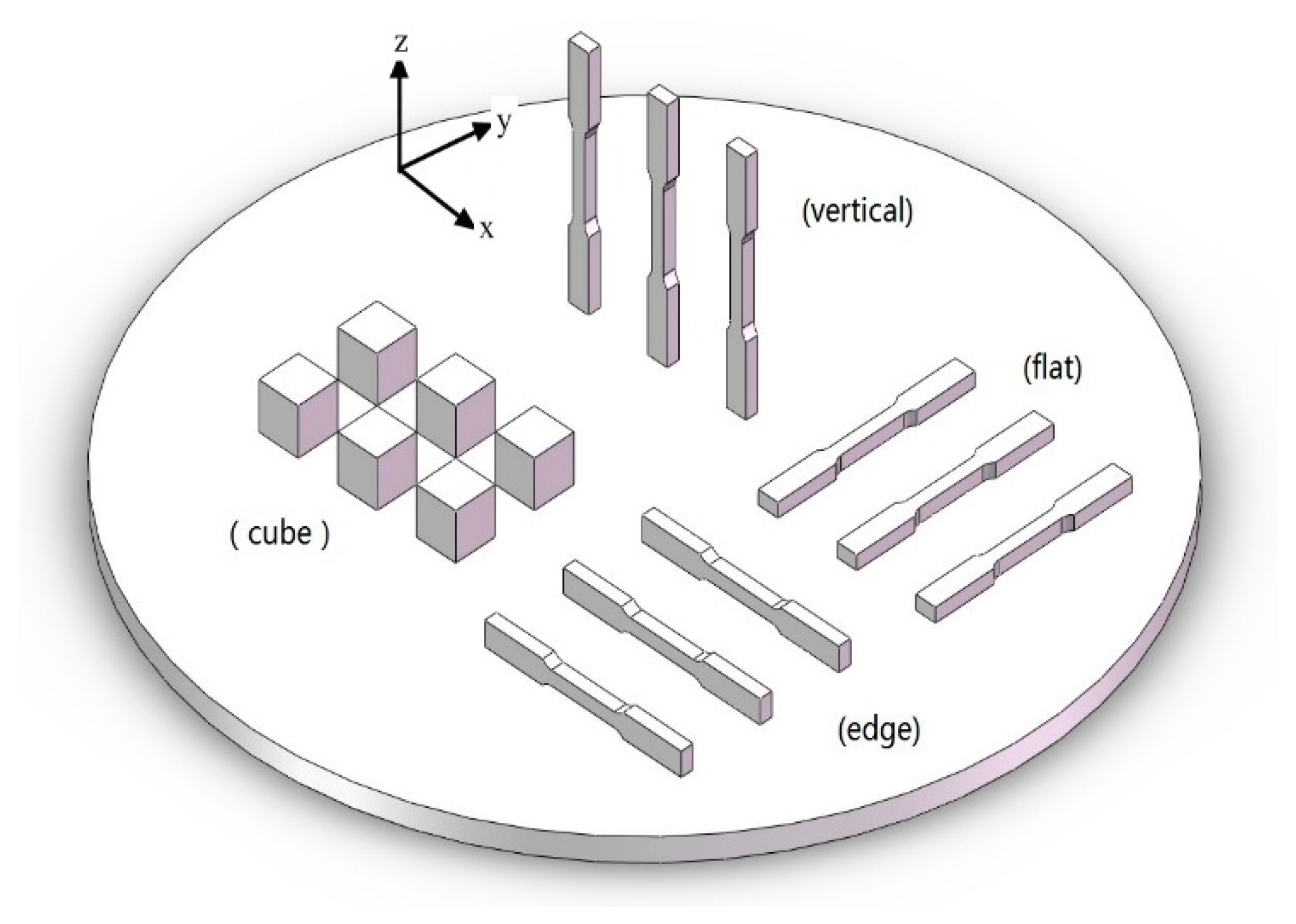
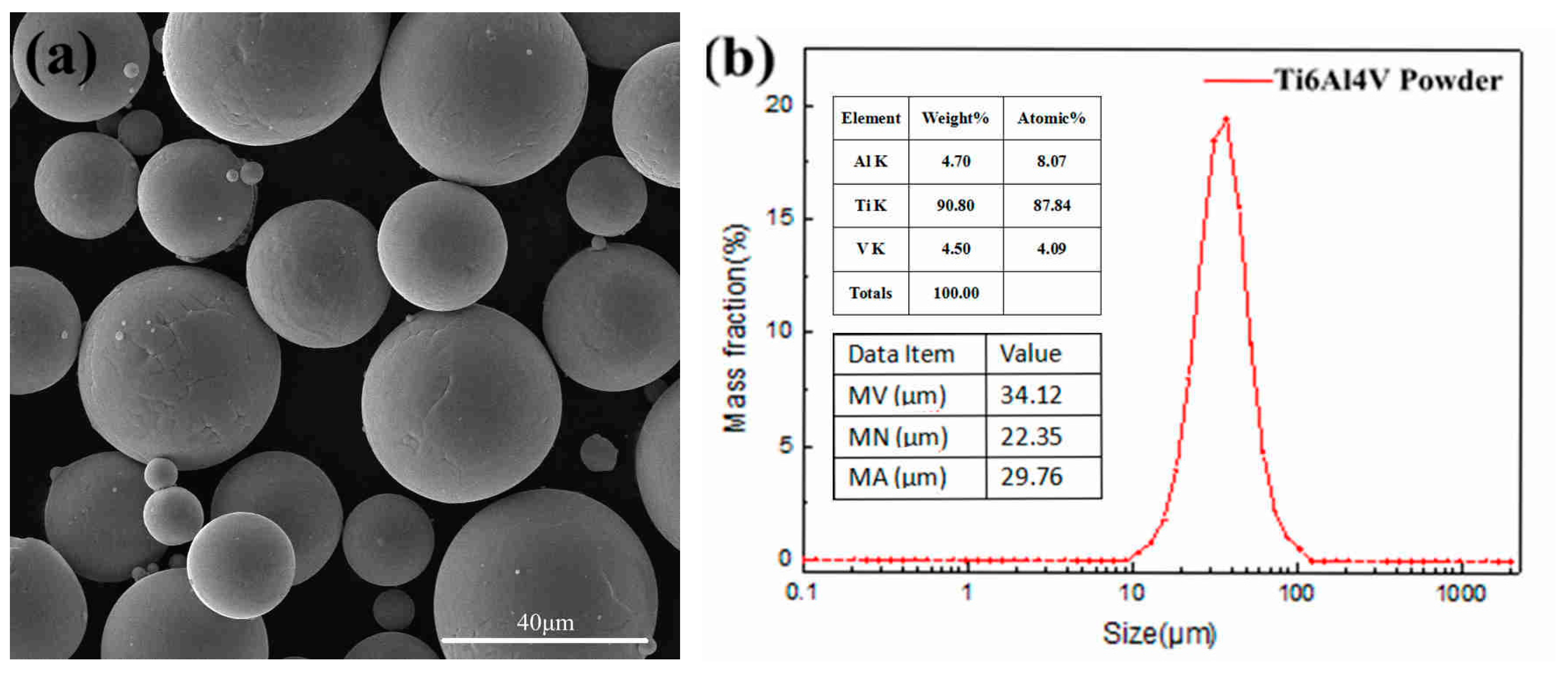
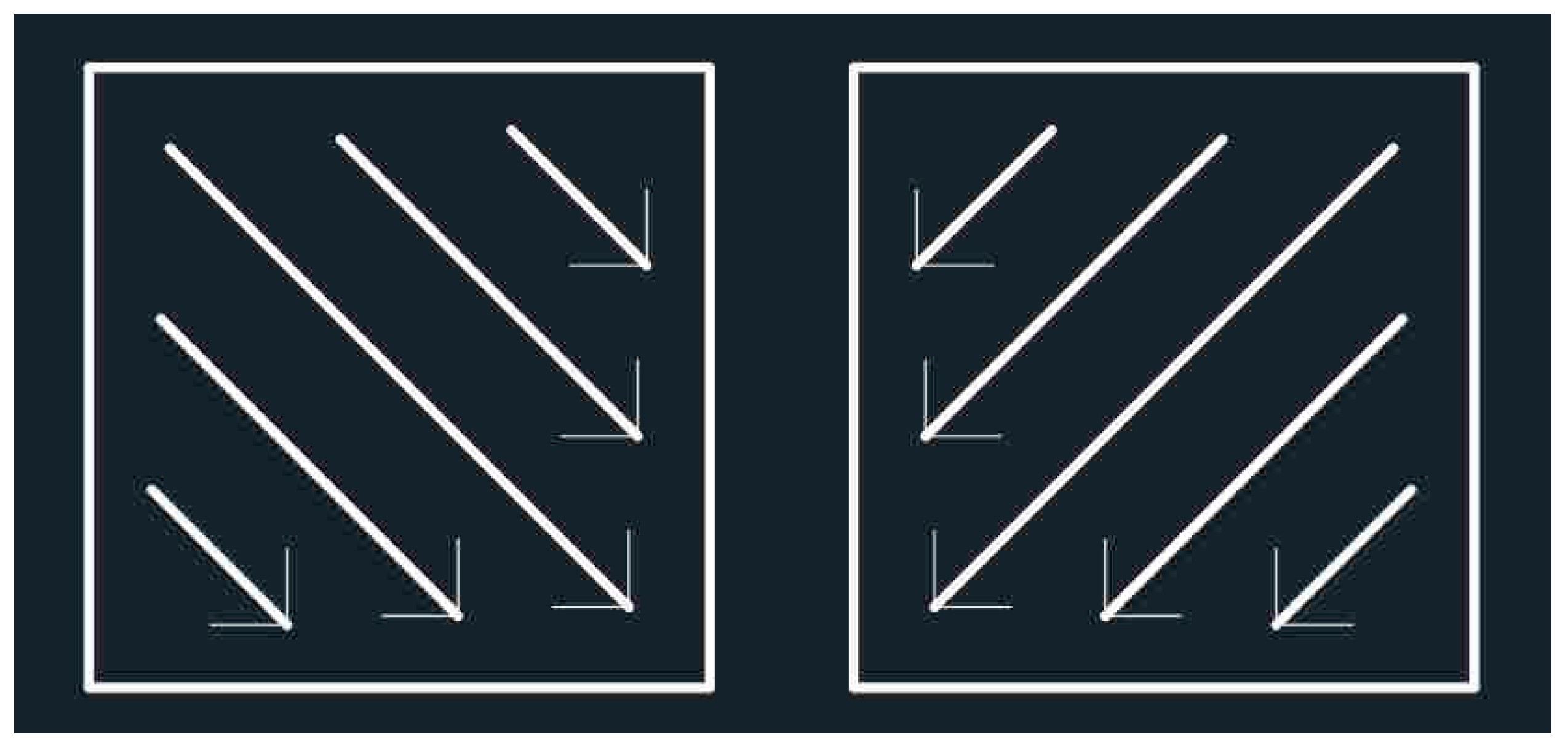
2. Material Preparation and Methods
3. Results and Discussion
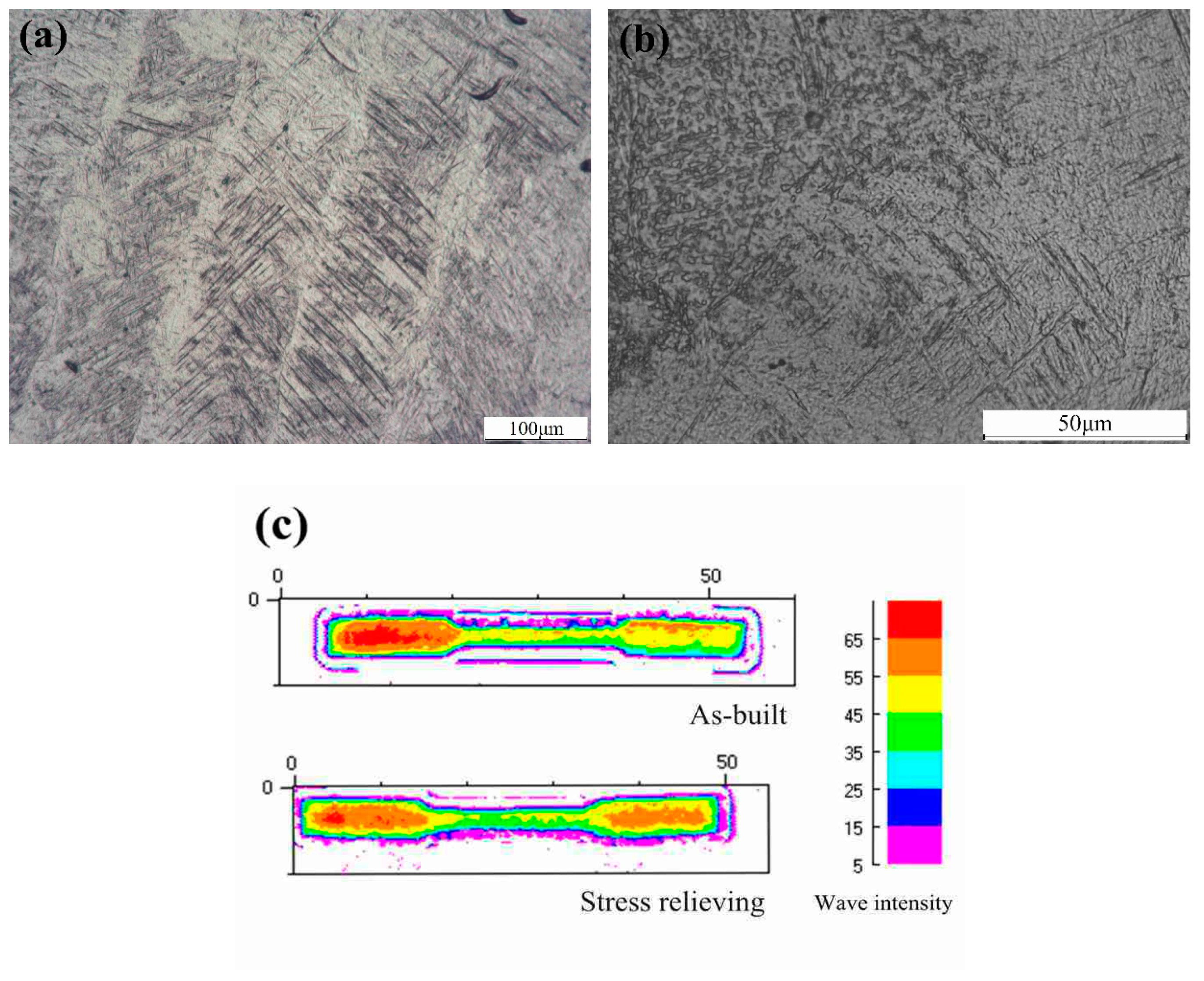
3.1. Microstructure
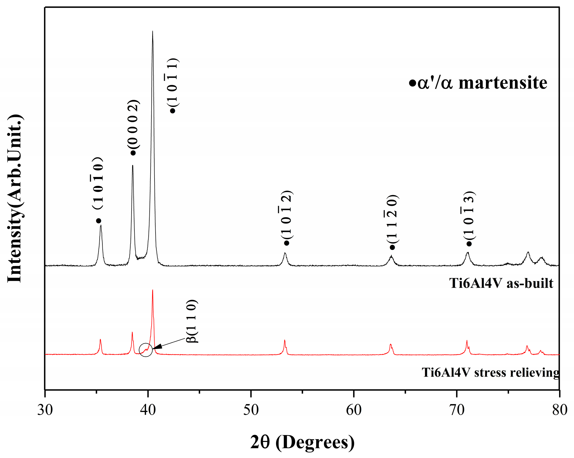
3.1.1. XRD Analysis
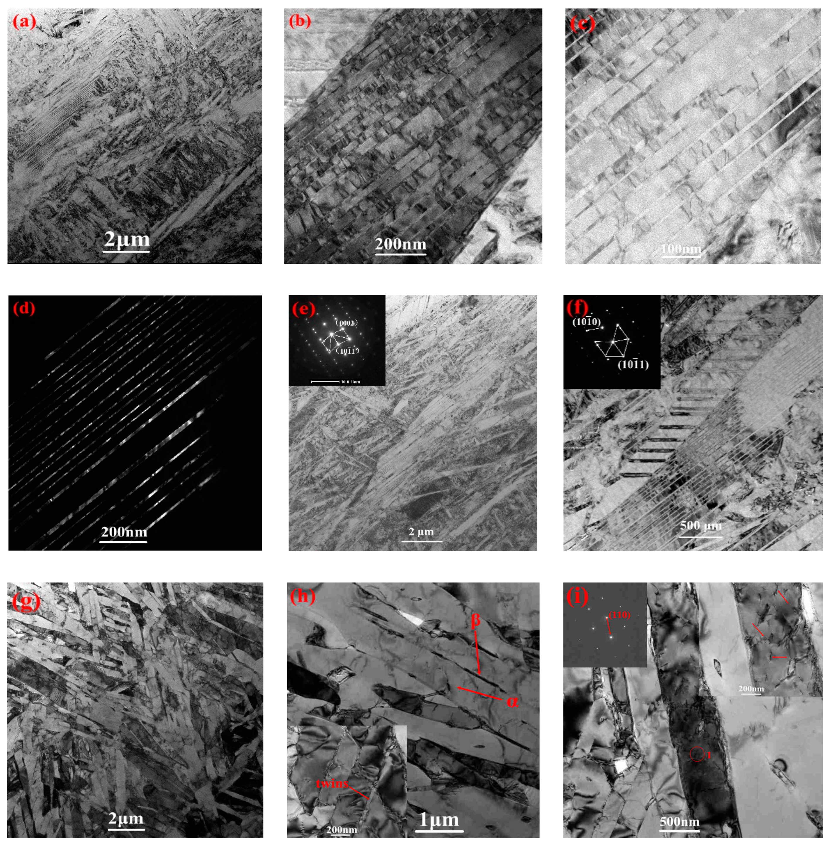
3.1.2. Microstructural Mechanism
3.2. Mechanical Properties
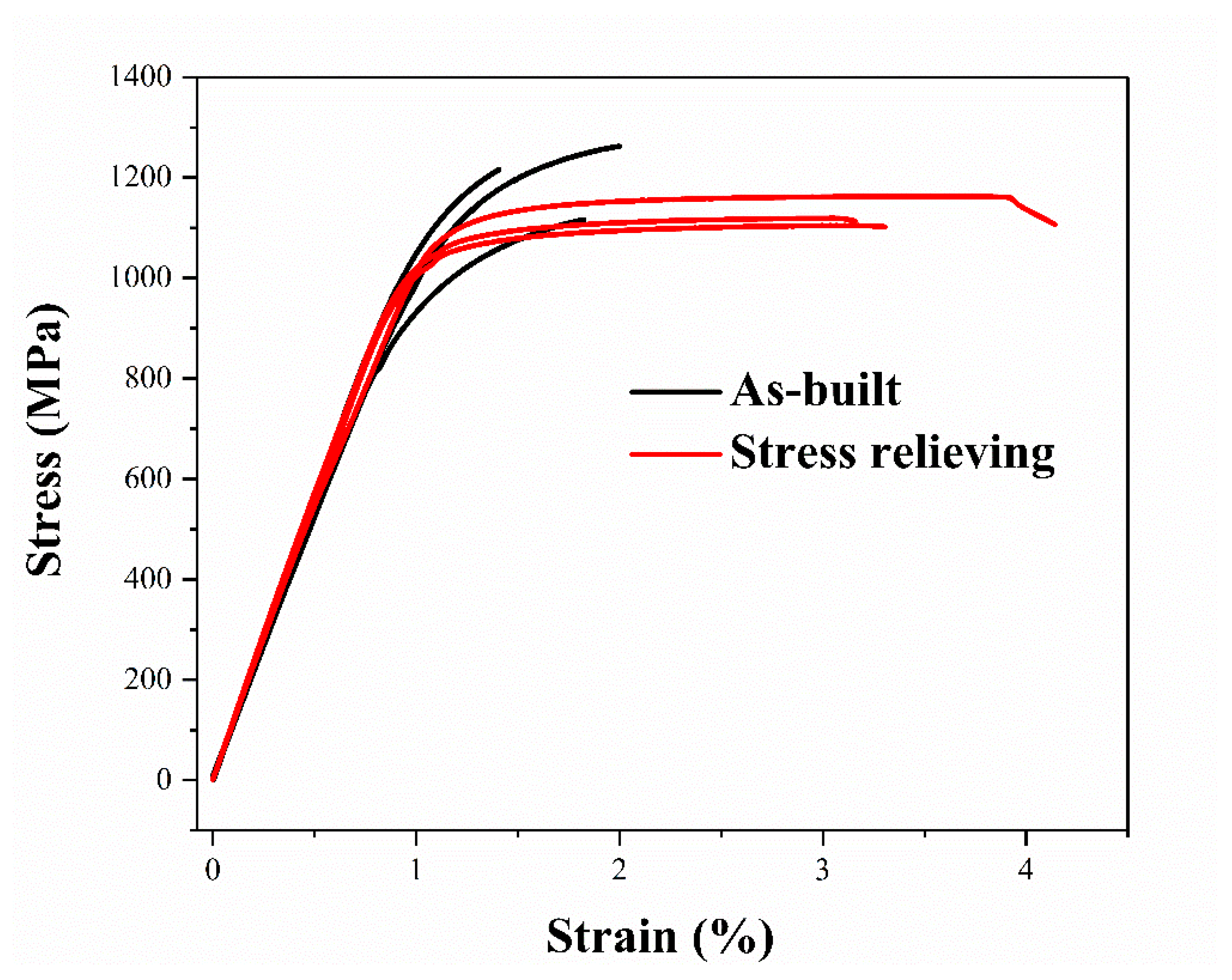
3.2.1. Tensile Properties
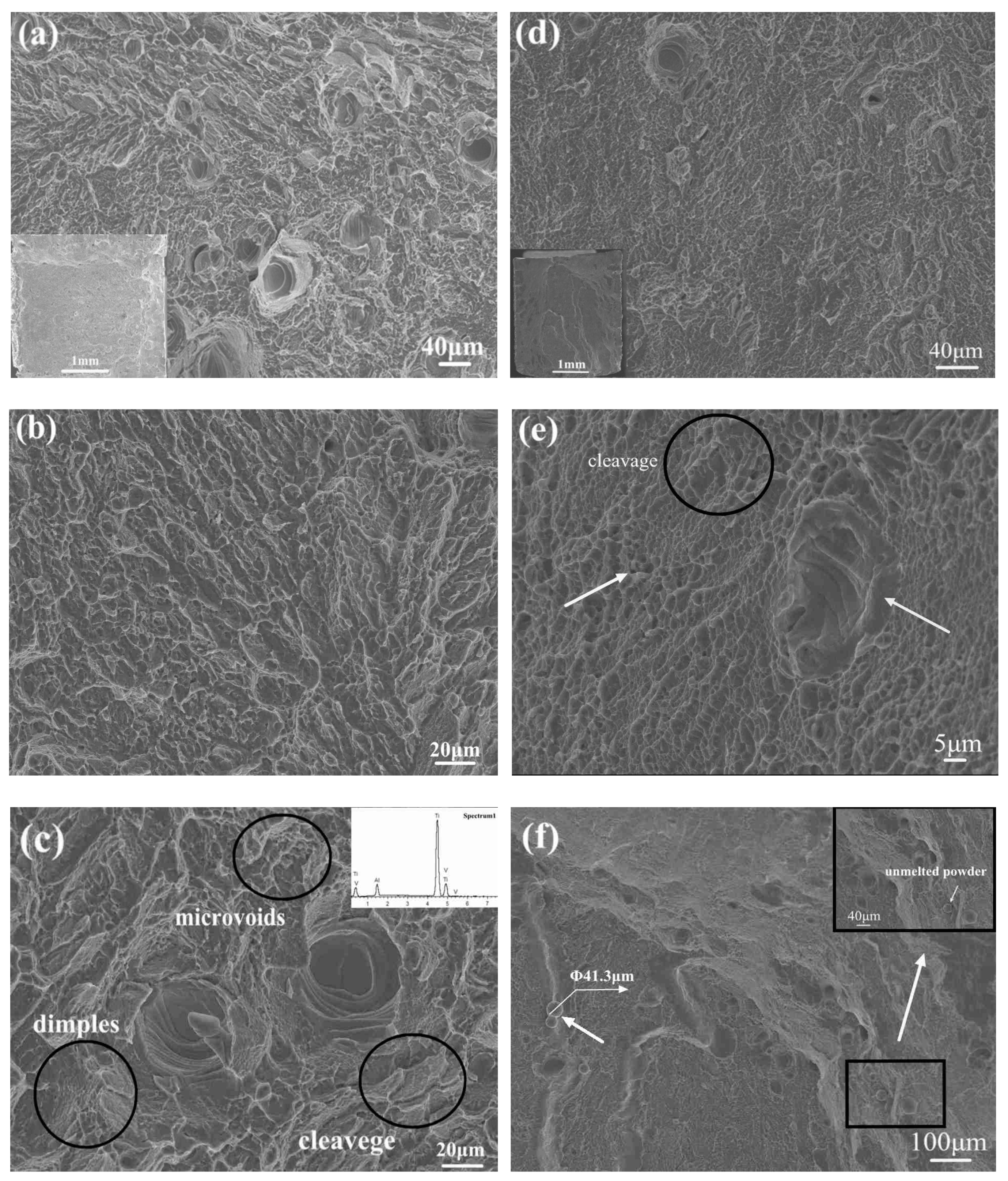
3.2.2. Tensile Fracture Mechanisms
4. Conclusions
- (1)
- After stress relieving, the β phase was observed in XRD pattern, OM metallograph and TEM images, and the composition of α’ phase reduced, indicating that the α’ phase decomposed during annealing treatment.
- (2)
- The width of the coarse β phase may have a further relationship with the width of laser scan track.
- (3)
- In as-built samples, the high dislocation density, twinning and stacking faults were detected, and the typical () twinning plane were marked where the clearly dislocation lines were discovered. In stress-relieved samples, a fully disordered α + β phase filled in the TEM images, and there were neither high density of dislocation nor stacking faults. Only fine dislocation lines and a little twinning remained.
- (4)
- α’ phase resulted in an increase in tensile strength and hardness and a decrease in plasticity. The poor plasticity was ascribed to the print mode, remained support structures and large thermal stresses.
Author Contributions
Funding
Acknowledgments
Conflicts of Interest
References
- Yadroitsev, I.; Thivillon, L.; Bertrand, P.; Smurov, I. Strategy of manufacturing components with designed internal structure by selective laser melting of metallic powder. Appl. Surf. Sci. 2007, 254, 980–983. [Google Scholar] [CrossRef]
- Ikeshoji, T.T.; Nakamura, K.; Yonehara, M.; Imai, K.; Kyogoku, H. Selective laser melting of pure copper. JOM 2018, 70, 396–400. [Google Scholar] [CrossRef]
- Herzog, D.; Seyda, V.; Wycisk, E.; Emmelmann, C. Additive manufacturing of metals. Acta Mater. 2016, 117, 371–392. [Google Scholar] [CrossRef]
- Demir, A.G.; Previtali, B. Additive manufacturing of cardiovascular CoCr stents by selective laser melting. Mater. Des. 2017, 119, 338–350. [Google Scholar] [CrossRef]
- Beese, A.M.; Carroll, B.E. Review of mechanical properties of Ti-6Al-4V made by laser-based additive manufacturing using powder feedstock. JOM 2016, 68, 724–734. [Google Scholar] [CrossRef]
- Azizi, H.; Zurob, H.; Bose, B.; Ghiaasiaan, S.R.; Wang, X.; Coulson, S.; Duz, V.; Phillion, A.B. Additive manufacturing of a novel Ti-Al-V-Fe alloy using selective laser melting. Addit. Manuf. 2018, 21, 529–535. [Google Scholar] [CrossRef]
- Tan, S.; Li, D.; Liu, H.; Liao, X.; Jiang, L. Microstructure and mechanical properties of 80Ni20Cr alloy manufactured by laser 3D printing technology. Chin. J. Nonferr. Met. 2017, 27. (In Chinese) [Google Scholar] [CrossRef]
- Dutta, B.; Froes, F.S. The additive manufacturing (AM) of titanium alloys. Met. Powder Rep. 2017, 72, 96–106. [Google Scholar] [CrossRef]
- Sutton, A.T.; Kriewall, C.S.; Leu, M.C.; Newkirk, J.W. Powder characterisation techniques and effects of powder characteristics on part properties in powder-bed fusion processes. Virtual Phys. Prototyp. 2017, 12, 3–29. [Google Scholar] [CrossRef]
- Wang, D.; Dou, W.; Yang, Y. Research on selective laser melting of Ti6Al4V: Surface morphologies, optimized processing zone, and ductility improvement mechanism. Metals 2018, 8, 471. [Google Scholar] [CrossRef]
- Bobbio, L.D.; Qin, S.; Dunbar, A.; Michaleris, P.; Beese, A.M. Characterization of the strength of support structures used in powder bed fusion additive manufacturing of Ti-6Al-4V. Addit. Manuf. 2017, 14, 60–68. [Google Scholar] [CrossRef]
- Buchanan, C.; Matilainen, V.P.; Salminen, A.; Gardner, L. Structural performance of additive manufactured metallic material and cross-sections. J. Constr. Steel Res. 2017, 136, 35–48. [Google Scholar] [CrossRef]
- Ma, C.P.; Guan, Y.C.; Zhou, W. Laser polishing of additive manufactured Ti alloys. Opt. Lasers Eng. 2017, 93, 171–177. [Google Scholar] [CrossRef]
- Alfaify, A.Y.; Hughes, J.; Ridgway, K. Critical evaluation of the pulsed selective laser melting process when fabricating Ti64 parts using a range of particle size distributions. Addit. Manuf. 2018, 19, 197–204. [Google Scholar] [CrossRef]
- Gong, H.; Rafi, K.; Gu, H.; Starr, T.; Stucker, B. Analysis of defect generation in Ti-6Al-4V parts made using powder bed fusion additive manufacturing processes. Addit. Manuf. 2014, 1, 87–98. [Google Scholar] [CrossRef]
- Khorasani, A.; Gibson, I.; Awan, U.S.; Ghaderi, A. The effect of SLM process parameters on density, hardness, tensile strength and surface quality of Ti-6Al-4V. Addit. Manuf. 2019, 25, 176–186. [Google Scholar] [CrossRef]
- Kudzal, A.; McWilliams, B.; Hofmeister, C.; Kellogg, F.; Yu, J.; Taggart-Scarff, J.; Liang, J. Effect of scan pattern on the microstructure and mechanical properties of powder bed fusion additive manufactured 17-4 stainless steel. Mater. Des. 2017, 133, 205–215. [Google Scholar] [CrossRef]
- Neikter, M.; Woracek, R.; Maimaitiyili, T.; Scheffzük, C.; Strobl, M.; Antti, M.L.; Åkerfeldt, P.; Pederson, R.; Bjerkén, C. Alpha texture variations in additive manufactured Ti-6Al-4V investigated with neutron diffraction. Addit. Manuf. 2018, 23, 225–234. [Google Scholar] [CrossRef]
- Zhao, X.; Li, S.; Zhang, M.; Liu, Y.; Sercombe, T.B.; Wang, S.; Hao, Y.; Yang, R.; Murr, L.E. Comparison of the microstructures and mechanical properties of Ti-6Al-4V fabricated by selective laser melting and electron beam melting. Mater. Des. 2016, 95, 21–31. [Google Scholar] [CrossRef]
- Simonelli, M.; Tse, Y.Y.; Tuck, C. Effect of the build orientation on the mechanical properties and fracture modes of SLM Ti-6Al-4V. Mater. Sci. Eng. A 2014, 616, 1–11. [Google Scholar] [CrossRef]
- Krakhmalev, P.; Fredriksson, G.; Yadroitsava, I.; Kazantseva, N.; Du Plessis, A.; Yadroitsev, I. Deformation behavior and microstructure of Ti6Al4V manufactured by SLM. Phys. Procedia 2016, 83, 778–788. [Google Scholar] [CrossRef]
- Sallica-Leva, E.; Caram, R.; Jardini, A.L.; Fogagnolo, J.B. Ductility improvement due to martensite α′ decomposition in porous Ti-6Al-4V parts produced by selective laser melting for orthopedic implants. J. Mech. Beha. Biomed. Mater. 2016, 54, 149–158. [Google Scholar] [CrossRef] [PubMed]
- Vrancken, B.; Thijs, L.; Kruth, J.P.; Van Humbeeck, J. Heat treatment of Ti6Al4V produced by Selective Laser Melting: Microstructure and mechanical properties. J. Alloys Compd. 2012, 541, 177–185. [Google Scholar] [CrossRef]
- Simonelli, M.; Tse, Y.Y.; Tuck, C. On the texture formation of selective laser melted Ti-6Al-4V. Metall. Mater. Trans. A 2014, 45, 2863–2872. [Google Scholar] [CrossRef]
- Zhao, Z.Y.; Li, L.; Bai, P.K.; Jin, Y.; Wu, L.Y.; Li, J.; Guan, R.G.; Qu, H.Q. The Heat treatment influence on the microstructure and hardness of TC4 titanium alloy manufactured via selective laser melting. Materials 2018, 11, 1318. [Google Scholar] [CrossRef] [PubMed]
- Rafi, H.K.; Karthik, N.V.; Gong, H.; Starr, T.L.; Stucker, B.E. Microstructures and mechanical properties of Ti6Al4V parts fabricated by selective laser melting and electron beam melting. J. Mater. Eng. Perform. 2013, 22, 3872–3883. [Google Scholar] [CrossRef]
- Xu, W.; Brandt, M.; Sun, S.; Elambasseril, J.; Liu, Q.; Latham, K.; Xia, K.; Qian, M. Additive manufacturing of strong and ductile Ti-6Al-4V by selective laser melting via in situ martensite decomposition. Acta Mater. 2015, 85, 74–84. [Google Scholar] [CrossRef]
- Vrancken, B.; Cain, V.; Knutsen, R.; Van Humbeeck, J. Residual stress via the contour method in compact tension specimens produced via selective laser melting. Scr. Mater. 2014, 87, 29–32. [Google Scholar] [CrossRef]
- Yadroitsava, I.; Grewar, S.; Hattingh, D.; Yadroitsev, I. Residual stress in SLM Ti6Al4V alloy specimens. Mater. Sci. Forum 2015, 828, 305–310. [Google Scholar] [CrossRef]
- Tiferet, E.; Rivin, O.; Ganor, M.; Ettedgui, H.; Ozeri, O.; Caspi, E.N.; Yeheskel, O. Structural investigation of selective laser melting and electron beam melting of Ti-6Al-4V using neutron diffraction. Addit. Manuf. 2016, 10, 43–46. [Google Scholar] [CrossRef]
- Simonelli, M.; Tse, Y.Y.; Tuck, C. Microstructure of Ti-6Al-4V produced by selective laser melting. J. Phys. Conf. Ser. 2012, 371, 012084. [Google Scholar] [CrossRef]
- Liu, J.; To, A.C. Quantitative texture prediction of epitaxial columnar grains in additive manufacturing using selective laser melting. Addit. Manuf. 2017, 16, 58–64. [Google Scholar] [CrossRef]
- Mantri, S.A.; Banerjee, R. Microstructure and micro-texture evolution of additively manufactured β-Ti alloys. Addit. Manuf. 2018, 23, 86–98. [Google Scholar] [CrossRef]
- Yamanaka, K.; Saito, W.; Mori, M.; Matsumoto, H.; Chiba, A. Preparation of weak-textured commercially pure titanium by electron beam melting. Addit. Manuf. 2015, 8, 105–109. [Google Scholar] [CrossRef]
- Liu, Z.C.; Ren, H.P.; Ji, Y.P. The New Theory of Solid State Phase Transformation; Science Press: Beijing, China, 2015. (In Chinese) [Google Scholar]
- Britton, T.B.; Dunne, F.P.E.; Wilkinson, A.J. On the mechanistic basis of deformation at the microscale in hexagonal close-packed metals. Proc. R. Soc. A Math. Phys. Eng. Sci. 2015, 471, 20140881. [Google Scholar] [CrossRef]
- Prashanth, K.G.; Damodaram, R.; Maity, T.; Wang, P.; Eckert, J. Friction welding of selective laser melted Ti6Al4V parts. Mater. Sci. Eng. A 2017, 704, 66–71. [Google Scholar] [CrossRef]
- Hartunian, P.; Eshraghi, M. Effect of Build Orientation on the Microstructure and Mechanical Properties of Selective Laser-Melted Ti-6Al-4V Alloy. J. Manuf. Mater. Process. 2018, 2, 69. [Google Scholar] [CrossRef]


| Process Parameters | Values |
|---|---|
| Laser power (W) | 135 |
| Layer thickness (μm) | 30 |
| Exposure time (μs) | 400 |
| Scan speed (mm/s) | 800 |
| Laser spot size (μm) | 52 |
| Element | Ti | Al | V | O |
|---|---|---|---|---|
| Ti6Al4V | 89.84 | 6.25 | 3.90 | <0.1 |
| Samples | Phase | ||
|---|---|---|---|
| α’/% | α/% | β/% | |
| As-built | 28.50 | 71.50 | 0 |
| Stress relieving | 9.90 | 79.55 | 10.55 |
| Parameters | Elastic Modulus (GPa) | Yield Strength (MPa) | Ultimate Tensile Strength (MPa) | Fracture Stress (MPa) | Fracture Elongation (%) | Hardness (HV) |
|---|---|---|---|---|---|---|
| As-built | 107 ± 4 | 1142 ± 17 | 1235 ± 37 | 1235 ± 37 | 1.3 ± 0.5 | 395 ± 21 |
| Stress relieving | 114 ± 2 | 1057 ± 25 | 1130 ± 30 | 1129 ± 30 | 2.8 ± 0.4 | 390 ± 18 |
© 2019 by the authors. Licensee MDPI, Basel, Switzerland. This article is an open access article distributed under the terms and conditions of the Creative Commons Attribution (CC BY) license (http://creativecommons.org/licenses/by/4.0/).
Share and Cite
He, J.; Li, D.; Jiang, W.; Ke, L.; Qin, G.; Ye, Y.; Qin, Q.; Qiu, D. The Martensitic Transformation and Mechanical Properties of Ti6Al4V Prepared via Selective Laser Melting. Materials 2019, 12, 321. https://doi.org/10.3390/ma12020321
He J, Li D, Jiang W, Ke L, Qin G, Ye Y, Qin Q, Qiu D. The Martensitic Transformation and Mechanical Properties of Ti6Al4V Prepared via Selective Laser Melting. Materials. 2019; 12(2):321. https://doi.org/10.3390/ma12020321
Chicago/Turabian StyleHe, Junjie, Duosheng Li, Wugui Jiang, Liming Ke, Guohua Qin, Yin Ye, Qinghua Qin, and Dachuang Qiu. 2019. "The Martensitic Transformation and Mechanical Properties of Ti6Al4V Prepared via Selective Laser Melting" Materials 12, no. 2: 321. https://doi.org/10.3390/ma12020321
APA StyleHe, J., Li, D., Jiang, W., Ke, L., Qin, G., Ye, Y., Qin, Q., & Qiu, D. (2019). The Martensitic Transformation and Mechanical Properties of Ti6Al4V Prepared via Selective Laser Melting. Materials, 12(2), 321. https://doi.org/10.3390/ma12020321