On the Influence of Capillary-Based Structural Health Monitoring on Fatigue Crack Initiation and Propagation in Straight Lugs

 ,
,
Abstract
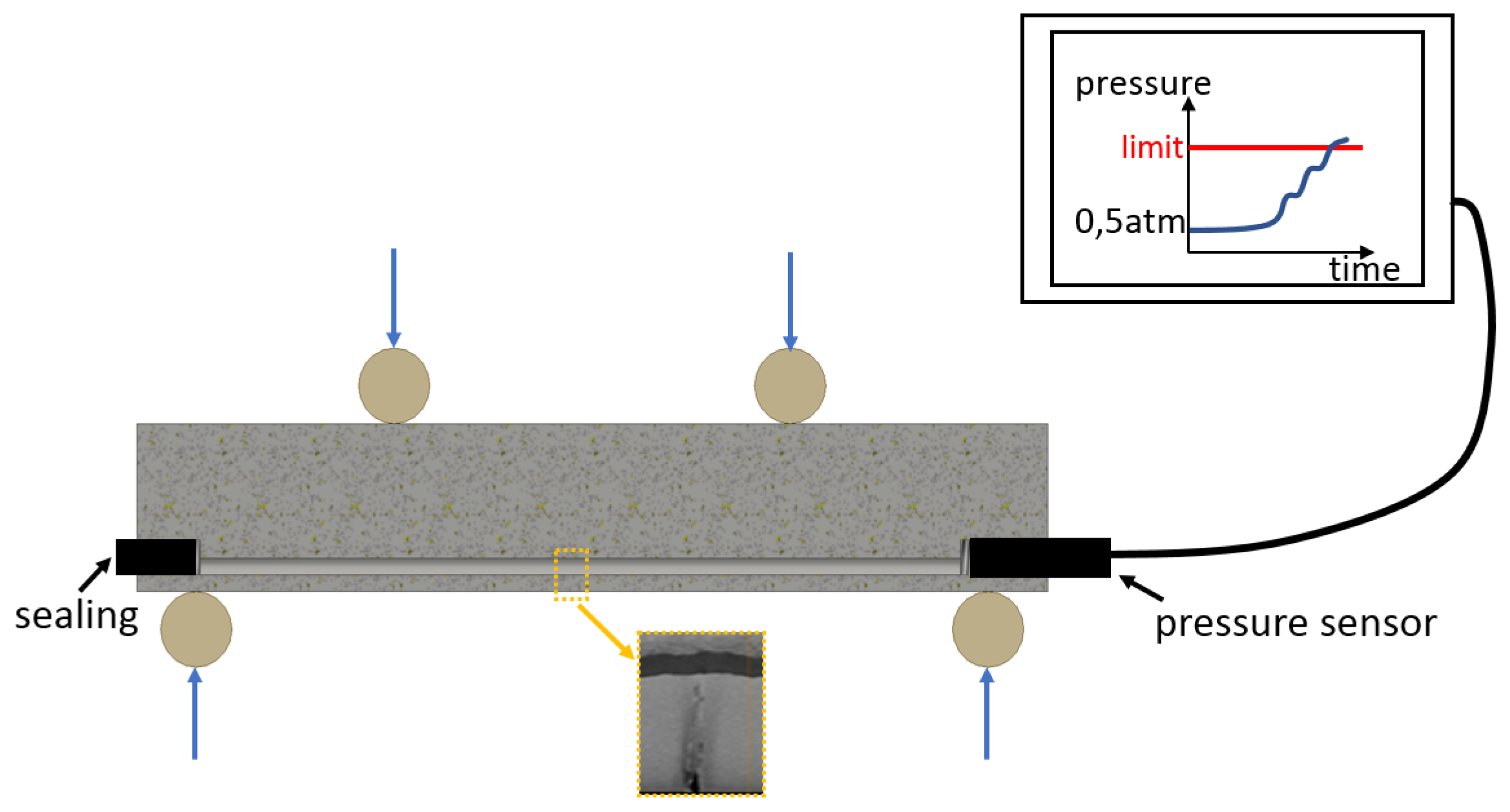
1. Introduction
2. Crack Initiation Considerations
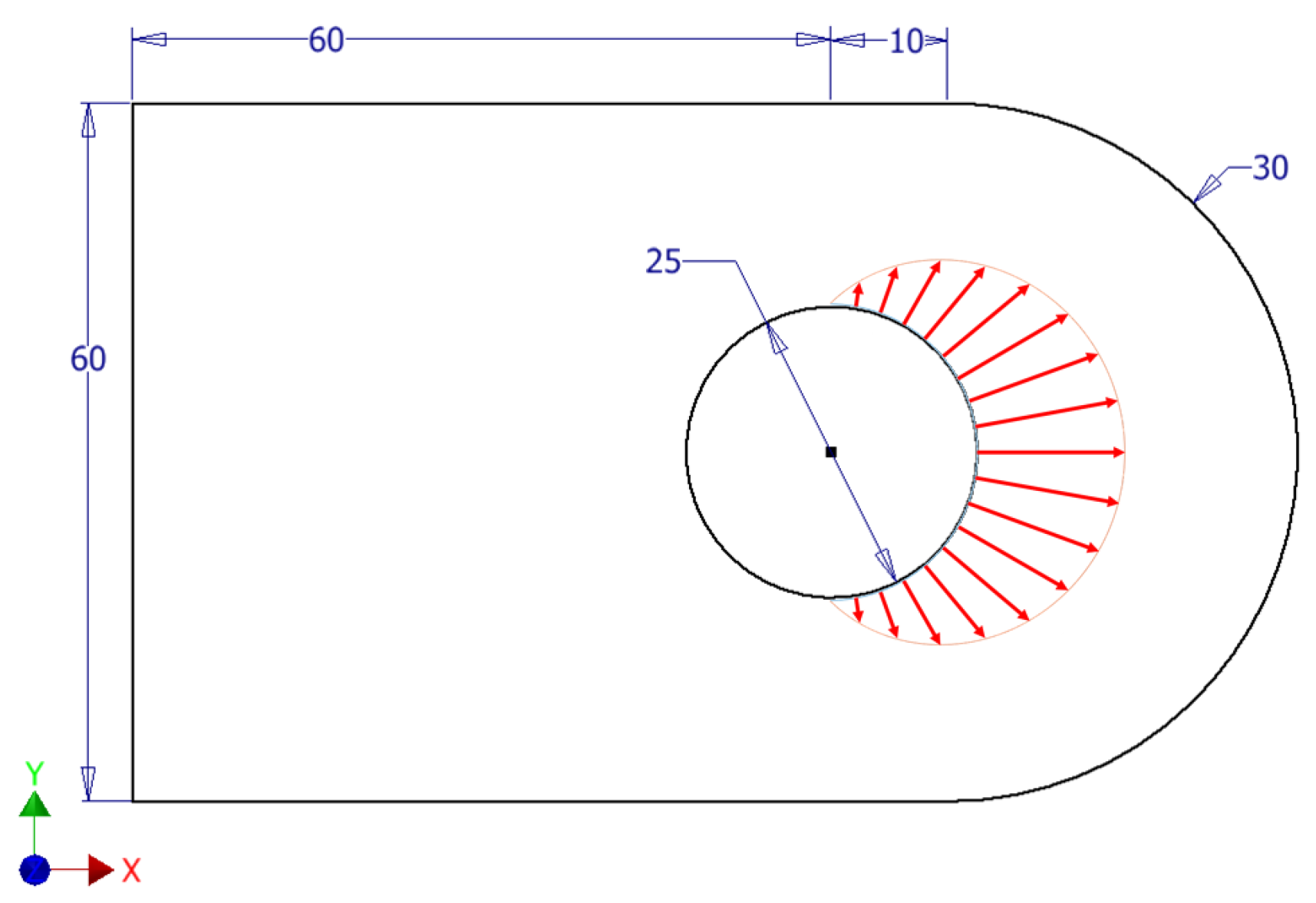
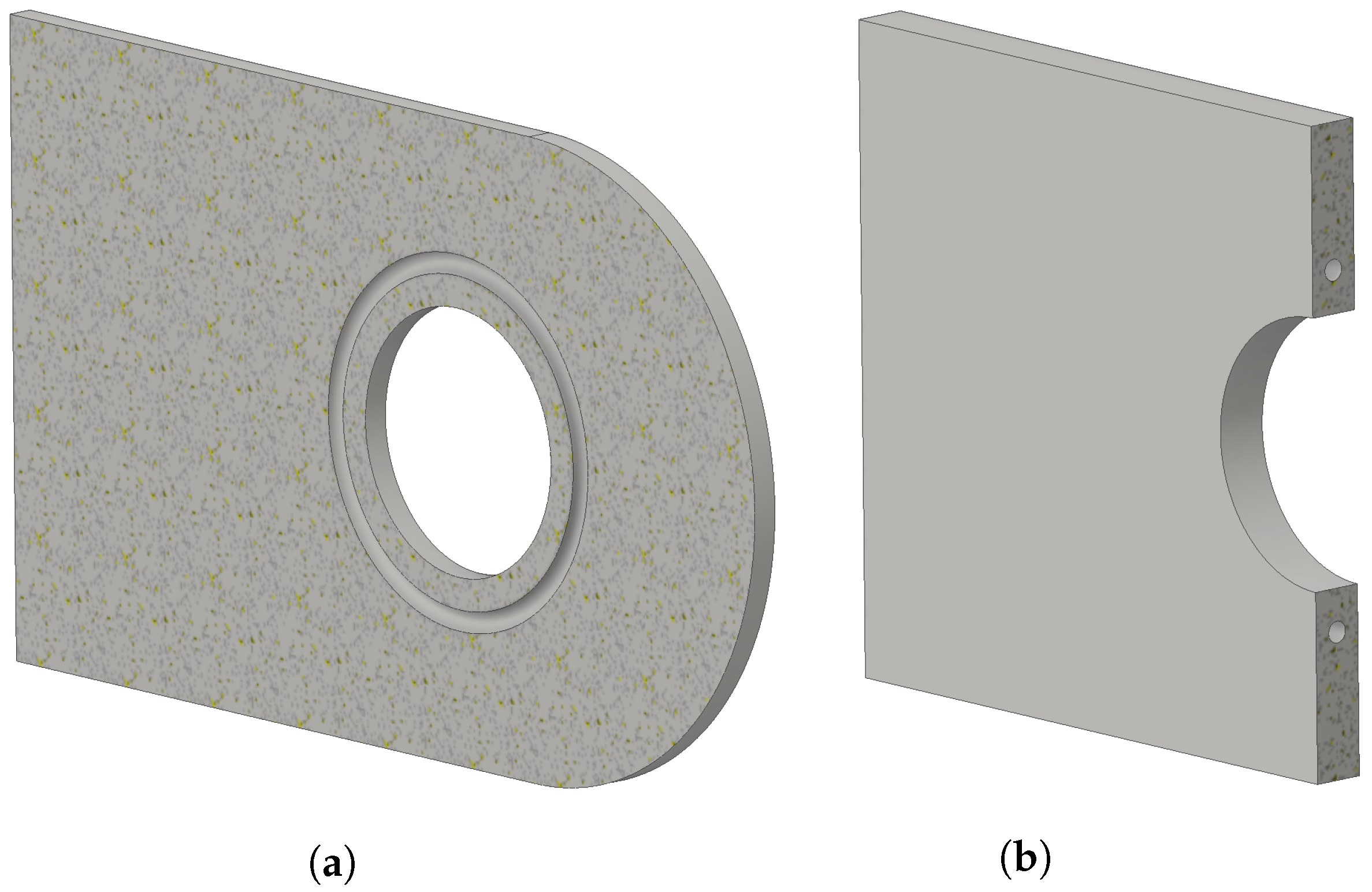
2.1. Numerical Framework
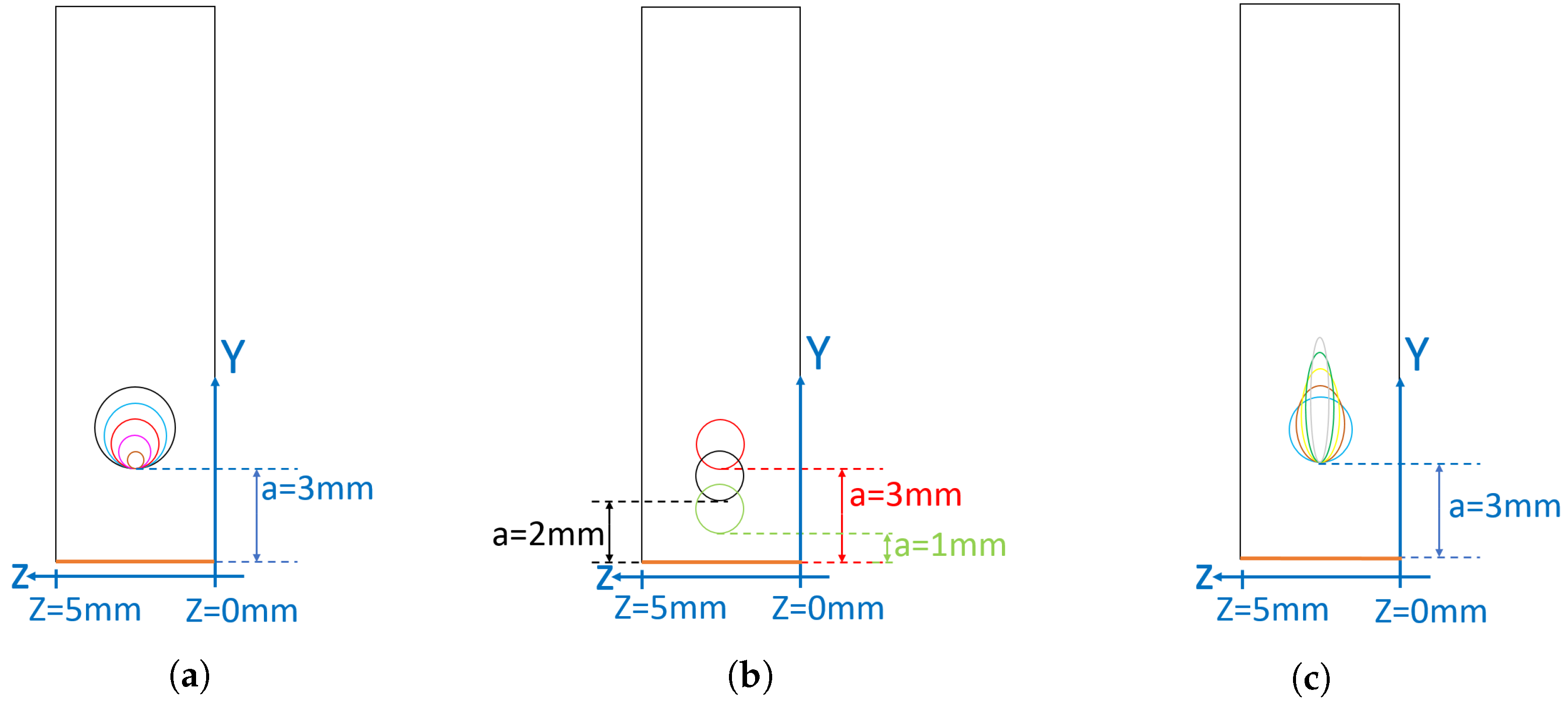
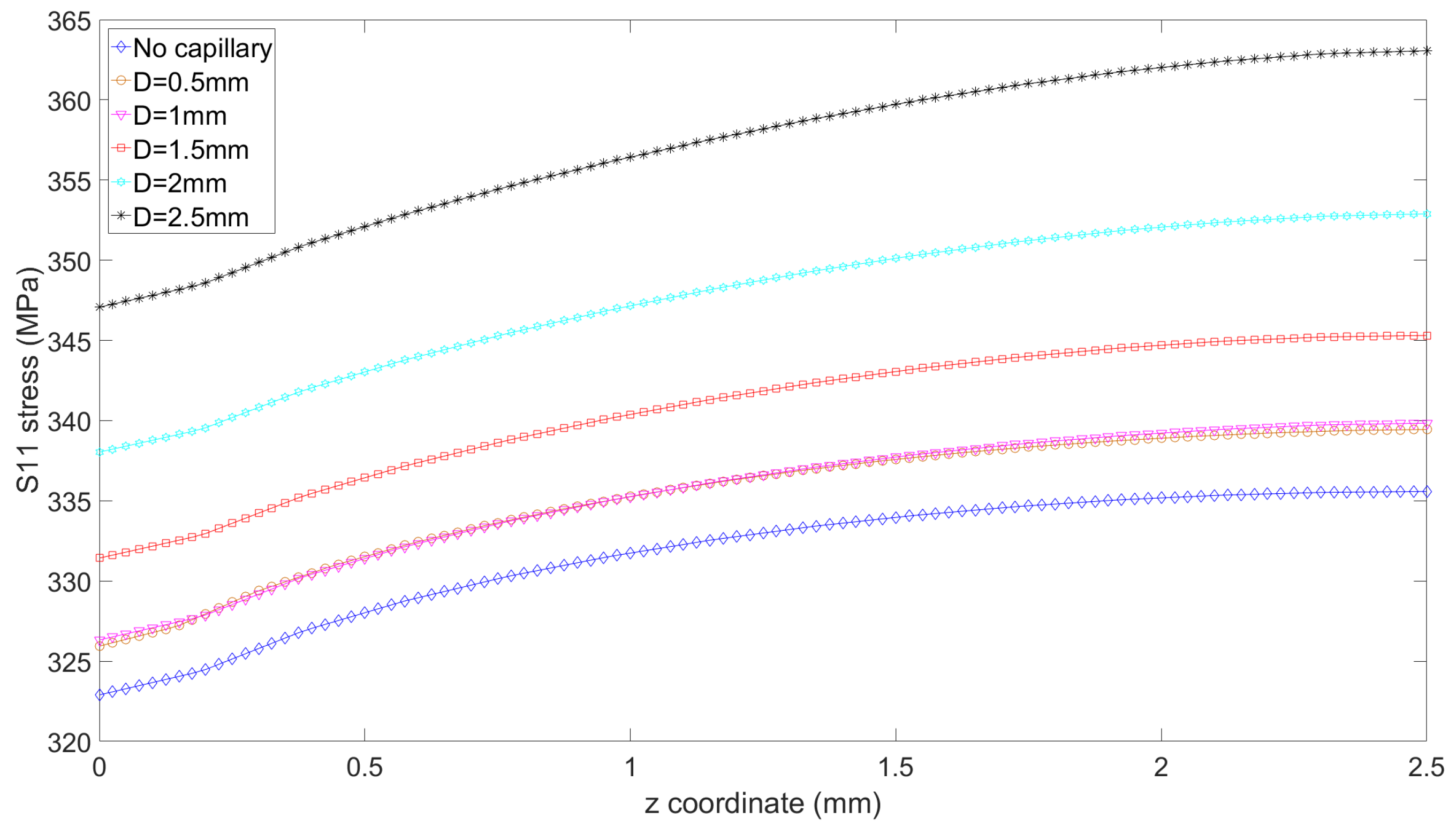
2.2. Circular Capillary—Influence of Diameter
2.3. Circular Capillary—Influence of Edge-to-Edge Distance
2.4. Elliptical Capillary—Influence of Ellipse Aspect Ratio
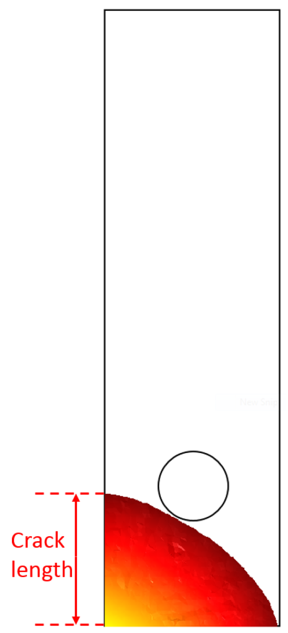
3. Crack Propagation Considerations
3.1. Numerical Framework
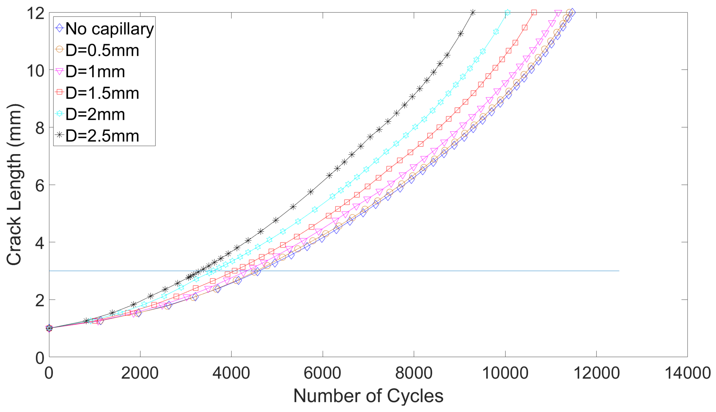
3.2. Influence of Capillary Diameter on Crack Growth Life
3.3. Influence of Capillary Shape on the Crack Growth Life
4. Conclusions
Author Contributions
Funding
Acknowledgments
Conflicts of Interest
References
- Suresh, S. Fatigue of Materials; Cambridge University Press: Cambridge, UK, 1998. [Google Scholar]
- Noels, L. Fracture Mechanics Online Class. Available online: http://www.ltas-cm3.ulg.ac.be/FractureMechanics/?p=welcome (accessed on 4 August 2019).
- Federal Aviation Administration. Lessons Learned from Civil Aviations Accidents: De Havilland DH-106 Comet 1. Available online: https://lessonslearned.faa.gov/ll_main.cfm?TabID=1&LLID=28&LLTypeID=0 (accessed on 4 August 2019).
- Findlay, S.J.; Harrrison, N.D. Why Aircraft Fail. Mater. Today 2002, 5, 18–25. [Google Scholar] [CrossRef]
- Gorelik, M. Additive Manufacturing in the Context of Structural Integrity. Int. J. Fatigue 2017, 94, 168–177. [Google Scholar] [CrossRef]
- De Baere, D.; Strantza, M.; Hinderdael, M.; Devesse, W.; Guillaume, P. Effective Structural Health Monitoring with Additive Manufacturing. In Proceedings of the 7th European Workshop on Structural Health Monitoring, Nantes, France, 8–11 July 2014; pp. 2314–2321. [Google Scholar]
- De Baere, D.; Hinderdael, M.; Moonens, M.; Jardon, Z.; Lison, M.; Strantza, M.; Guillaume, P. Additive Manufactured Metallic Smart Structures to Monitor the Mechanical Behavior In Situ. Proceeding 2018, 2, 500. [Google Scholar] [CrossRef]
- Deraemaeker, A.; Worden, K. New Trends in Vibration Based Structural Health Monitoring; CISM Lecture Notes Volume 520; Springer: Vienna, Austria, 2010. [Google Scholar]
- Ahmed, S.; Thostenson, E.T.; Schumacher, T.; Doshi, S.M.; McConnell, J.R. Integration of Carbon Nanotube Sensing Skins and Carbonfiber Composites for Monitoring and Structural Repair of Fatigue Cracked Metal Structures. Compos. Struct. 2018, 203, 182–192. [Google Scholar] [CrossRef]
- Abot, J.L. Structural Health Monitoring Using Carbon Nanotube Yarns: Sensing Concept and Applications in Composites. In Proceedings of the 5th International Symposium on Sensor Science (I3S 2017), Barcelona, Spain, 27–29 September 2017; Volume 1, p. 852. [Google Scholar]
- Roach, D. Real Time Crack Detection Using Mountable Comparative Vacuum Monitoring Sensors. Smart Struct. Syst. 2009, 5, 317–328. [Google Scholar] [CrossRef]
- Farrar, C.R.; Worden, K. An Introduction to Structural Health Monitoring. Philos. Trans. R. A Math. Phys. Eng. Sci. 2007, 365, 303–315. [Google Scholar] [CrossRef] [PubMed]
- De Baere, D. Structural Health Monitoring Using Hollow Cavity Structure. European Patent EP2801809A1, 12 November 2014. [Google Scholar]
- Moonens, M.; Wyart, E.; Hinderdael, M.; De Baere, D.; Guillaume, P. Numerical Simulation of Fatigue Crack Growth in Straight Lugs Equipped with Efficient Structural Health Monitoring. Procedia Struct. Integr. 2018, 13. [Google Scholar] [CrossRef]
- Engels, G.P.; Thomas, M.C. Helicopter Blade Crack Detection System. U.S. Patent US5205710A, 27 April 1993. [Google Scholar]
- Strantza, M.; De Baere, D.; Rombouts, M.; Maes, G.; Guillaume, P.; Van Hemelrijck, D. Feasibility Study on Integrated Structural Health Monitoring Produced by Metal Three-Dimensional Printing. Struct. Health-Monit. Int. J. 2015, 14, 622–632. [Google Scholar] [CrossRef]
- Yadollahi, Y.; Shamsaei, N. Additive Manufacturing of Fatigue Resistant Materials: Challenges and Opportunities. Int. J. Fatigue 2017, 98, 14–31. [Google Scholar] [CrossRef]
- Leuders, S.; Thone, M.; Riemer, A.; Niendorf, T.; Troster, T.; Richard, H.A.; Maier, H.J. On the Mechanical Behavior of Titanium Alloy TiAl6V4 Manufactured by Selective Laser Melting: Fatigue Resistance and Crack Growth Performance. Int. J. Fatigue 2013, 48, 300–307. [Google Scholar] [CrossRef]
- Reschetnik, W.; Bruggemann, J.-P.; Aydinoz, M.E.; Grydin, O.; Hoyer, K.-P.; Kullmer, G.; Richard, H.A. Fatigue Crack Growth Behavior of Additively Processed EN AW-7075 Aluminium Alloy. Procedia Struct. Integr. 2016, 2, 3040–3048. [Google Scholar] [CrossRef]
- Riemer, A.; Richard, H.A. Crack Propagation in Additive Manufactured Materials and Structures. Procedia Struct. Integr. 2016, 2, 1229–1236. [Google Scholar] [CrossRef]
- Strantza, M. Additive Manufacturing as a Tool for Structural Health Monitoring of Metallic Structures. Ph.D. Thesis, Vrije Universiteit Brussel, Brussels, Belgium, 2016. [Google Scholar]
- Gunther, G.; Leuders, S.; Koppa, P.; Troster, T.; Henkel, S.; Biermann, H.; Niendorf, T. On the Effect of Internal Channels and Surface Roughness on the High-Cycle Fatigue Performance of Ti-6Al-4V Processed by SLM. Mater. Des. 2018, 143, 1–11. [Google Scholar] [CrossRef]
- Ambrogio, G.; Gagliardi, F.; Muzzupappa, M.; Filice, L. Additive-Incremental Forming Hybrid Manufacturing Technique to Improve Customized Part Performance. J. Manuf. Process. 2019, 37, 386–391. [Google Scholar] [CrossRef]
- Lauwers, B.; Klocke, F.; Klink, A.; Tekkaya, A.E.; Neugebauer, R.; Mcintosh, D. Hybrid Processes in Manufacturing. CIRP Ann. 2014, 63, 561–583. [Google Scholar] [CrossRef]
- Lhuissier, P.; de Formanoir, C.; Martin, G.; Dendievel, R.; Godet, S. Geometrical Control of Lattice Structures Produced by EBM through Chemical Etching: Investigations at the Scale of Individual Struts. Mater. Des. 2016, 110, 485–493. [Google Scholar] [CrossRef]
- Hinderdael, M.; De Baere, D.; Guillaume, P. Fatigue Performance of Powder Bed Fused Ti-6Al-4V Component with Integrated Chemically Etched Capillary for Structural Health Monitoring Application. Proceedings 2018, 2, 499. [Google Scholar] [CrossRef]
- Hinderdael, M.; De Baere, D.; Moonens, M.; Vafadari, R.; Guillaume, P. Effect of Surface Roughness on Fatigue Crack Initiation in Additive Manufactured Components with Integrated Capillary for SHM Application. In Proceedings of the International Committee on Aeronautical Fatigue and Structural Integrity, Nagoya, Japan, 5–9 June 2017. [Google Scholar]
- Schijve, J. Fatigue of Structures and Materials; Kluwer Academic Publishers: Dordrecht, The Netherlands, 2001. [Google Scholar]
- Schijve, J.; Hoeymakers, A.H.W. Fatigue Crack Growth in Lugs. Fatigue Eng. Mater. Struct. 1979, 1, 185–201. [Google Scholar] [CrossRef]
- Boljanovic, S.; Maksimovic, S. Fatigue Crack Growth Modelling of Attachment Lugs. Int. J. Fatigue 2014, 58, 66–74. [Google Scholar] [CrossRef]
- Paris, P.C.; Gomez, M.P.; Anderson, W.E. A Rational Analytic Theory of Fatigue. Trend Eng. 1961, 13, 9–14. [Google Scholar]
- Paris, P.C.; Erdogan, F. A Critical Analysis of Crack Propagation Laws. J. Basic Eng. 1963, 85, 528–533. [Google Scholar] [CrossRef]
- Wyart, E. Three-Dimensional Crack Analysis in Aeronautical Structures using the Substructured Finite Element/Extended Finite Element Method. Ph.D. Thesis, Université Catholique de Louvain, Ottignies-Louvain-la-Neuve, Belgium, 2007. [Google Scholar]
- Duflot, M. A Study of the Representation of Cracks with Level Sets. Int. J. Numer. Methods Eng. 2007, 70, 1261–1302. [Google Scholar] [CrossRef]
- Moës, N.; Dolbow, J.; Belytschko, T. A Finite Element Method for Crack Growth without Re-meshing. Int. J. Numer. Methods Eng. 1999, 46, 131–150. [Google Scholar] [CrossRef]
- Geuzaine, C.; Remacle, J.-F. Gmsh: A Three Dimensional Finite Element Mesh Generator with Built-in Pre- and Post-processing Facilities. Int. J. Numer. Methods Eng. 2009, 79, 1309–1331. [Google Scholar] [CrossRef]


| D (mm) | (MPa) | (MPa) | |
|---|---|---|---|
| Reference | 336 | - | - |
| 0.5 | 339 | +0.9% | 198 |
| 1 | 340 | +1.2% | 204 |
| 1.5 | 345 | +2.6% | 214 |
| 2 | 352 | +4.8% | 226 |
| 2.5 | 363 | +8.0% | 245 |
| a (mm) | (MPa) | (MPa) | |
|---|---|---|---|
| Reference | 336 | - | - |
| 1 | 351 | +4.5% | 260 |
| 2 | 347 | +3.3% | 226 |
| 3 | 345 | +2.7% | 214 |
| AR | (MPa) | (MPa) | |
|---|---|---|---|
| Reference | 336 | - | - |
| 1 (circular) | 352 | +4.8% | 226 |
| 1.56 | 350 | +4.2% | 199 |
| 2.25 | 349 | +3.9% | 183 |
| 3.06 | 348 | +3.6% | 176 |
| 4.0 | 347 | +3.3% | 174 |
| D (mm) | (% of ) | |||
|---|---|---|---|---|
| Reference | 11,470 | - | - | - |
| 0.5 | 11,400 | −0.6% | 4500 | 61 |
| 1 | 11,160 | −2.7% | 4470 | 60 |
| 1.5 | 10,630 | −7.3% | 4070 | 62 |
| 2 | 10,050 | −12.4% | 3605 | 64 |
| 2.5 | 9290 | −19% | 3380 | 63 |
| D (mm) | (% of ) | |||
|---|---|---|---|---|
| Reference | 27,490 | - | - | - |
| 0.5 | 27,220 | −1% | 19,970 | 26 |
| 1 | 27,080 | −1.5% | 19,100 | 29 |
| 1.5 | 26,180 | −4.8% | 18,100 | 31 |
| 2 | 24,130 | −12.2% | 16,870 | 30 |
| 2.5 | 22,520 | −18% | 15,070 | 33 |
| AR (-) | |||
|---|---|---|---|
| 1 | 10,050 | - | 3605 |
| 1.56 | 9920 | −1.3% | 3805 |
| 2.25 | 9860 | −1.9% | 3900 |
| 3.06 | 9860 | −1.9% | 3990 |
| 4 | 9820 | −2.3%% | 4030 |
© 2019 by the authors. Licensee MDPI, Basel, Switzerland. This article is an open access article distributed under the terms and conditions of the Creative Commons Attribution (CC BY) license (http://creativecommons.org/licenses/by/4.0/).
Share and Cite
Moonens, M.; Wyart, E.; De Baere, D.; Hinderdael, M.; Ertveldt, J.; Jardon, Z.; Arroud, G.; Guillaume, P. On the Influence of Capillary-Based Structural Health Monitoring on Fatigue Crack Initiation and Propagation in Straight Lugs. Materials 2019, 12, 2965. https://doi.org/10.3390/ma12182965
Moonens M, Wyart E, De Baere D, Hinderdael M, Ertveldt J, Jardon Z, Arroud G, Guillaume P. On the Influence of Capillary-Based Structural Health Monitoring on Fatigue Crack Initiation and Propagation in Straight Lugs. Materials. 2019; 12(18):2965. https://doi.org/10.3390/ma12182965
Chicago/Turabian StyleMoonens, Marc, Eric Wyart, Dieter De Baere, Michaël Hinderdael, Julien Ertveldt, Zoé Jardon, Galid Arroud, and Patrick Guillaume. 2019. "On the Influence of Capillary-Based Structural Health Monitoring on Fatigue Crack Initiation and Propagation in Straight Lugs" Materials 12, no. 18: 2965. https://doi.org/10.3390/ma12182965
APA StyleMoonens, M., Wyart, E., De Baere, D., Hinderdael, M., Ertveldt, J., Jardon, Z., Arroud, G., & Guillaume, P. (2019). On the Influence of Capillary-Based Structural Health Monitoring on Fatigue Crack Initiation and Propagation in Straight Lugs. Materials, 12(18), 2965. https://doi.org/10.3390/ma12182965