1. Introduction:
Wear is a severe problem in a vast majority of industrial applications, leading to reduced durability of engineering components and increased frequency of replacement shutdowns. Protective coatings of carbide-based compositions have been extensively employed to enhance wear resistance, and the popular processing routes to produce them have included physical vapor deposition (PVD), chemical vapor deposition (CVD), thermal spray, etc. [
1]. Among these, thermal spraying offers unique advantages such as the ability to spray thicker protective layers, faster deposition rates, and cost efficiency. Historically, atmospheric plasma spraying (APS), high velocity oxy-fuel (HVOF) spraying, and more recently high-velocity air-fuel (HVAF) spraying techniques have progressively become the thermal spray methods of choice for depositing carbide-based coatings [
2]. A significant limitation of these techniques is their inability to process fine powders due to considerable feeding-related challenges [
3], although employing such feedstock can potentially result in improved tribological performance of the coatings [
4].
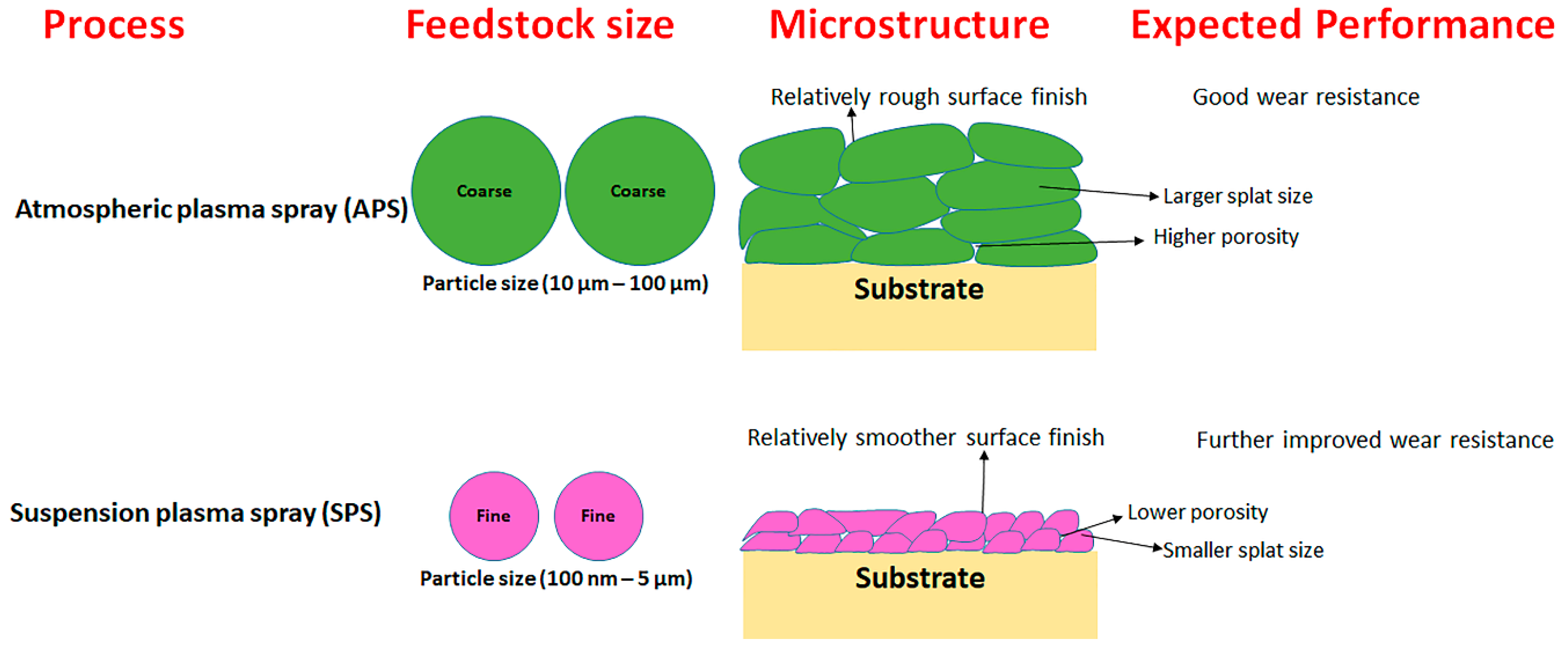
Suspension plasma spraying (SPS) is an advancement in APS, enabling spraying of fine feedstock (100 nm–5 µm diameter) [
5], and has already shown promise for yielding thermal barrier coatings (TBCs) with improved performance compared to APS [
6]. SPS coatings can similarly enhance wear performance due to unique microstructural features inherently associated with the process, such as the smaller splat size, fine scale porosity, low surface roughness, etc. An illustrative description of distinct microstructures resulting from the thermal spraying of different feedstock sizes, as well as their likely influence on wear performance, is shown in
Figure 1. Yet, the predominant focus of SPS research so far has been on TBCs. In particular, there have been very few prior efforts to deposit pure carbide coatings by SPS, which are ideal candidates for mitigating wear. Recently, Mubarok et al. reported SPS-processed SiC coatings, which exhibited excellent carbide phase retention post spraying [
7]. Berghaus et al. reported similar findings (minimal oxidation) for SPS-processed WC-Co coatings, demonstrating the capability of SPS to minimize the in-flight oxidation of carbide feedstock [
8]. The reason for the minimal oxidation of carbides in SPS-processed coatings compared to APS can be attributed to the presence of a solvent (ethanol or water) which consumes a considerable part of the plasma energy during its evaporation, thus minimizing feedstock decomposition.
Recognizing the above, the present study specifically deals with titanium carbide (TiC) and chromium carbide (Cr3C2) coatings (without any metal or alloy binder) produced by SPS. To the best of our knowledge, no prior attempts have been made to deposit TiC- and Cr3C2-based coatings via the SPS route. The SPS carbide coatings were comprehensively characterized using SEM, XRD, porosity, hardness, etc. The tribological behavior of the coatings under erosive, sliding, and abrasive wear modes was also evaluated.
2. Experimental Work
SSAB Domex® 350LA (low-alloyed steel, SSAB AB, Stockholm, Sweden) substrates were grit blasted to provide a surface roughness of approximately 3 µm Ra prior to spraying. Two experimental water-based suspensions, comprising 40 wt.% TiC and Cr
3C
2, respectively, were produced by the Treibacher Industrie AG (Althofen, Austria) for this work. Water-based suspensions were chosen due to their higher surface tension versus ethanol, which promotes the formation of relatively denser coatings [
9]. Particle size analysis of the liquid feedstock was performed using CILAS 1064 equipment (CILAS, Orleans, France). An Axial III plasma torch (Mettech Corp., Vancouver, Canada) was employed to deposit the coatings. The spray parameters used for SPS deposition of both the coatings are given in
Table 1. A gas mixture comprising argon, nitrogen, and hydrogen was used as the primary gas.
The surface morphology and cross-sectional microstructure of the coatings were analyzed using a scanning electron microscope (HITACHI TM-3000, Tokyo, Japan) in back-scattered electron (BSE) mode. Surface roughness was examined using a stylus-based profilometer (MITUTOYO SURFTEST-301, Kawasaki, Tokyo, Japan). Micro-hardness measurements were performed on the cross section of coatings (HMV-2 series, SHIMADZU Corp., Tokyo, Japan). Hardness testing was performed using a load of 980.7 mN (HV
0.1) and the dwell time was kept at 15 s. Ten independent measurements were made, and their mean and standard deviation values are reported herein. Porosity measurements were made using ImageJ software (version 1.52p, University of Wisconsin, Wisconsin, US)) [
10] by considering fifteen different cross-sectional SEM micrographs at 5000× magnification. XRD analysis of the top surface of as-sprayed coatings was performed using a high-energy intensity micro X-ray diffractometer (RAPID-II-D/MAX, Rigaku Corp., Tokyo, Japan). A slow scan rate comprising a step size of 0.01° and time of 10 s per step was utilized.
The as-sprayed specimens were polished to a surface roughness <1 µm on the Ra scale prior to wear testing. Three different wear tests (erosion, sliding, and abrasion) were performed in this work. The erosion test (TR-470, DUCOM, Bengaluru, India) was performed at room temperature according to the ASTM G76-13 standard [
11] at an impingement angle of 90°. Alumina of approximately 50 ± 10 µm mean particle size was used as the erodent media. During the test, the air pressure was maintained at 0.5 bar and the specimens (1-inch diameter coupons) were exposed to the erosion test for 10 min. The abrasive-wear test was performed as per ASTM G65 standard [
12] using a dry abrasion test rig from DUCOM (DUCOM instruments, Bangalore, India, 2019) with 80 mesh silica sand particles at a load of 5 kg. The speed of the wheel was kept at 245 ± 5 rpm and the abrasive flow rate was kept at 350 g/min. For the sliding-wear tests, specimens of size 10 mm ×10 mm × 4 mm were cut from the coated plates. Sliding wear tests were performed as per ASTM G99 standard [
13] by employing a coated pin (sintered WC-6Co) of diameter 6 mm, at a load of 5 kgf sliding against a disc rotated at 5 m/s velocity. The duration of this test was three hours and twenty minutes. In each of the above wear tests, the weight loss was measured using a high-accuracy weighing balance (Sartorius, Cubis® II, Sartorius Gmbh, Göttingen, Germany), accuracy: 0.01 mg). Three samples were used for erosion tests, while only one specimen was used for sliding- and abrasive-wear tests.
3. Results and Discussion
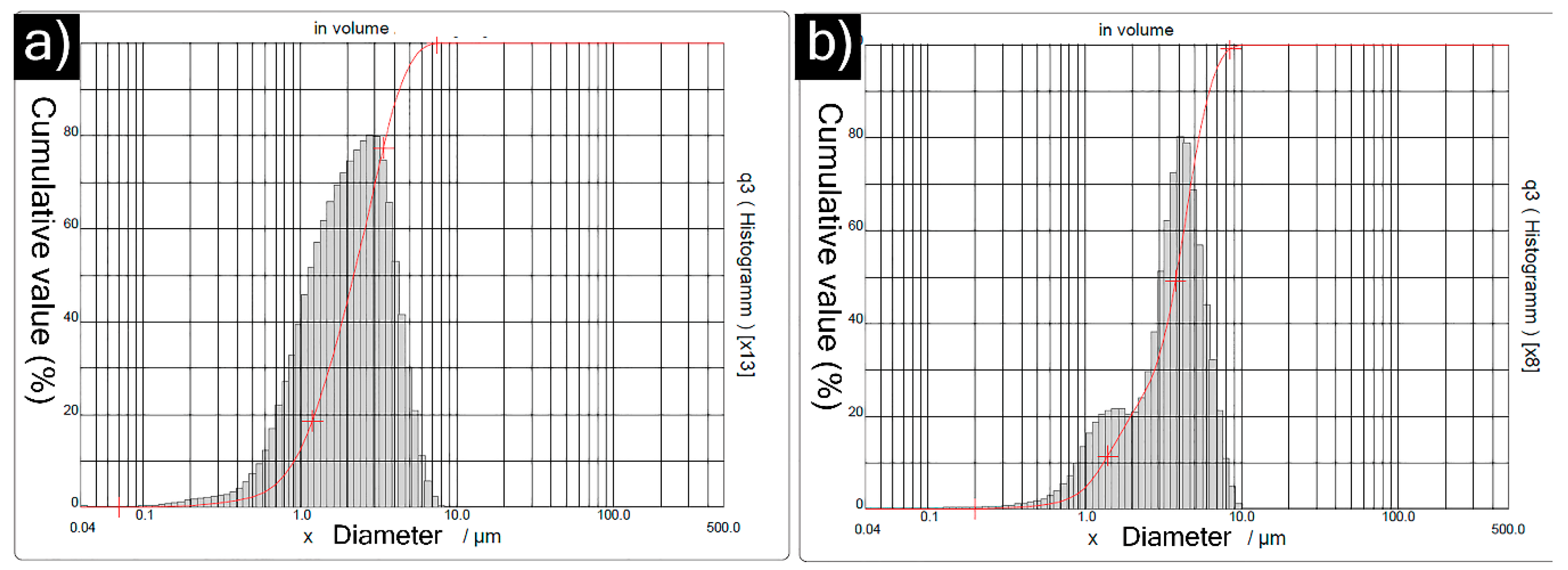
The particle size distribution of titanium carbide and chromium carbide feedstock is shown in
Figure 2a,b respectively. The median (D
50) particle size of titanium carbide was approximately 2.21 µm, and the D
90 was approximately 4.30 µm. The median (D
50) particle size of chromium carbide was 3.84 µm and D
90 was 6.25 µm. The particle size of chromium carbide was only slightly larger than that of titanium carbide, which is not expected to significantly influence splat size in the deposited coatings.
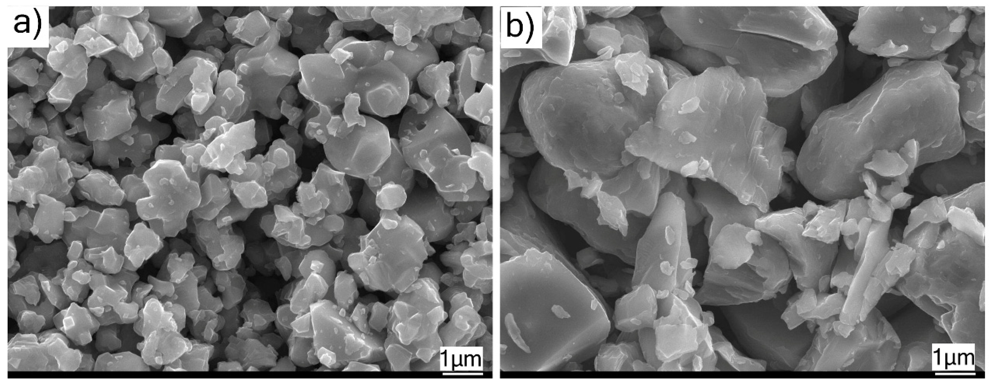
The SEM micrographs of TiC and Cr
3C
2 powders revealed that they were both comprised of irregularly shaped particles (see
Figure 3a,b). The Cr
3C
2 particles were clearly seen to be relatively coarser than the TiC particles, confirming the accompanying particle size distribution results, according to
Figure 3b.
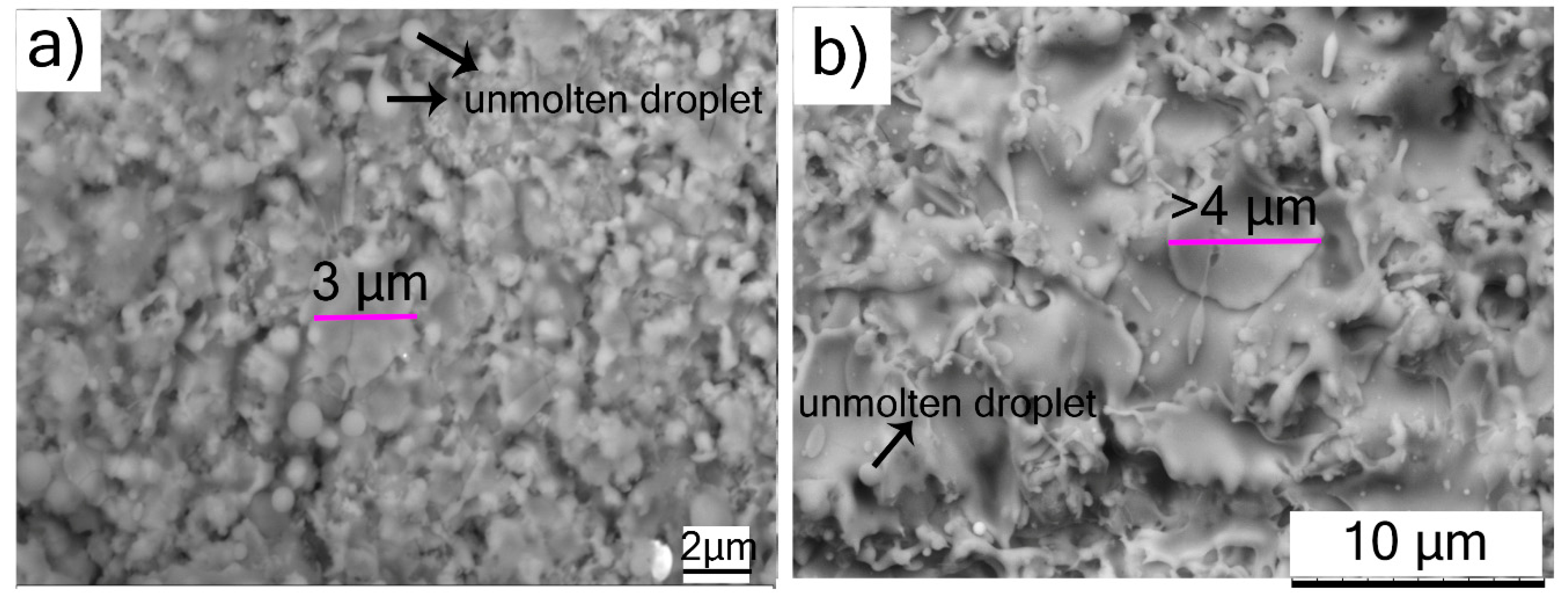
The top surface views of SPS-processed TiC and Cr
3C
2 coatings in
Figure 4 show fine-structured splats in the size range 3–4 µm, as compared to conventional powder-derived splats, which are at least an order of magnitude larger. The reason for the finer splat size in SPS can be directly attributed mainly to the considerably smaller particles in the feedstock. Moreover, the relatively lower droplet momentum in the case of SPS ensures that the droplets flatten to a lesser extent on impact with the substrate compared to conventional spray processes such as APS. This results in a much-refined microstructure in the case of the suspension-derived SPS coatings in comparison to the powder-derived APS coatings. The top-view SEM micrograph of the TiC coating shows unmolten spherical particles (see
Figure 4a). The Cr
3C
2 coating also showed fewer unmolten particles than those observed in TiC coating (
Figure 4b). The reason for lower unmolten particles in Cr
3C
2 (melting point: ~1800 °C [
14]) than TiC could be attributed to the significantly lower melting point of Cr
3C
2 compared to TiC (melting point: ~3100 °C). Furthermore, in both the SPS-processed coatings, the top surface morphology did not resemble the cauliflower-like microstructure as reported elsewhere for SPS-processed YSZ coatings, which accompanies the columnar microstructures desired for TBC applications [
6].
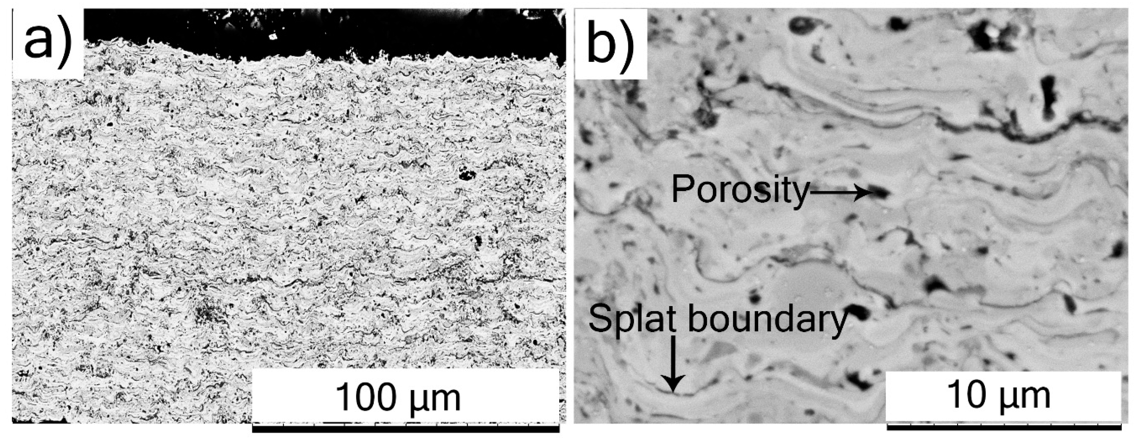
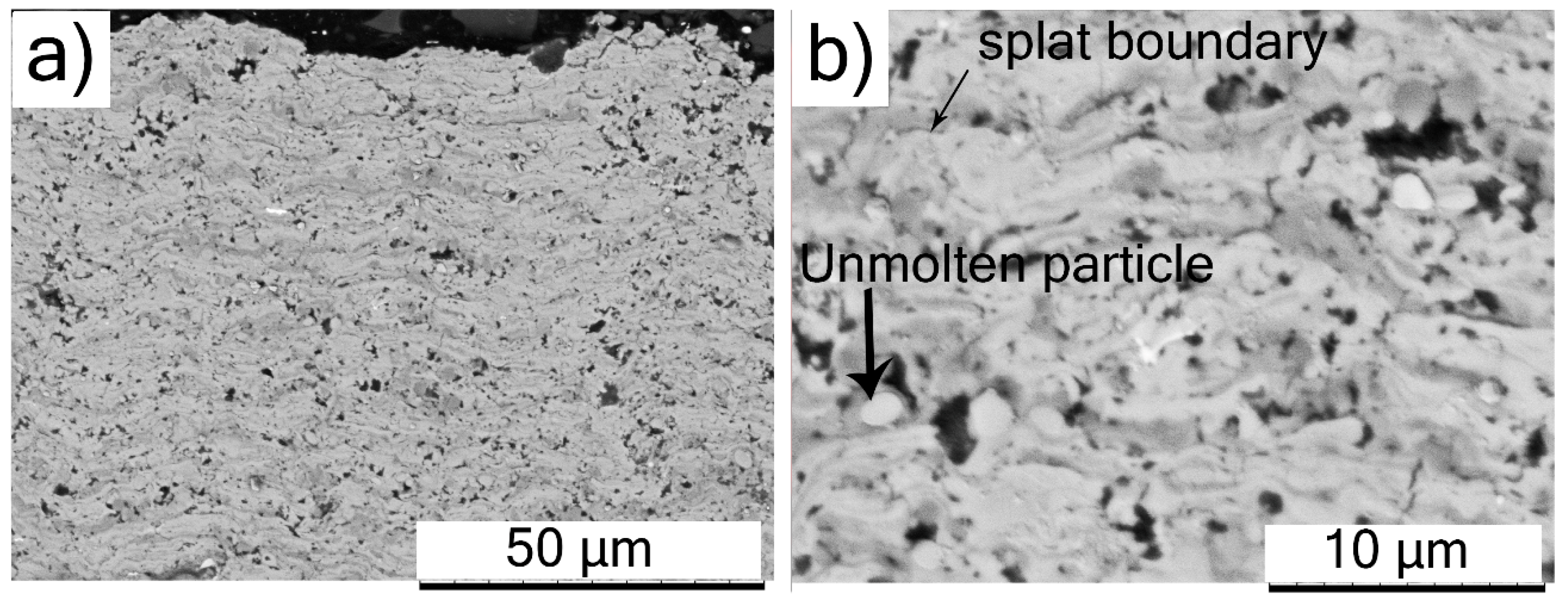
The low-magnification cross-sectional SEM micrograph of an SPS-processed TiC coating is shown in
Figure 5a, and reveals a largely homogeneous microstructure. The corresponding high-magnification cross-sectional SEM micrograph is more revealing, and shows uniformly distributed porosity with very few unmelted particles (
Figure 5b). Furthermore, the splat boundaries between successive splats could be discerned, but no inter-pass porosity was obvious, suggesting reasonably good inter-splat cohesion. Additionally, the cross-sectional SEM micrographs did not show any delamination cracks or separation at the splat boundaries, indicating good coating integrity.
The cross-sectional SEM micrograph of the Cr
3C
2 coating at low-magnification in
Figure 6a also showed uniform distribution of porosity. The high-magnification cross-sectional SEM micrograph in
Figure 6b shows inter-splat boundaries between successive splats. At certain locations, the splat boundaries in the Cr
3C
2 coating were observed to reveal separation between splats, indicating relatively poor cohesion. Notwithstanding the very promising results exhibited by the Cr
3C
2 coating as discussed subsequently, the above microstructural examination suggests that there clearly exists room for further optimization of coating quality by modifying suspension formulation and/or manipulating spray parameters.
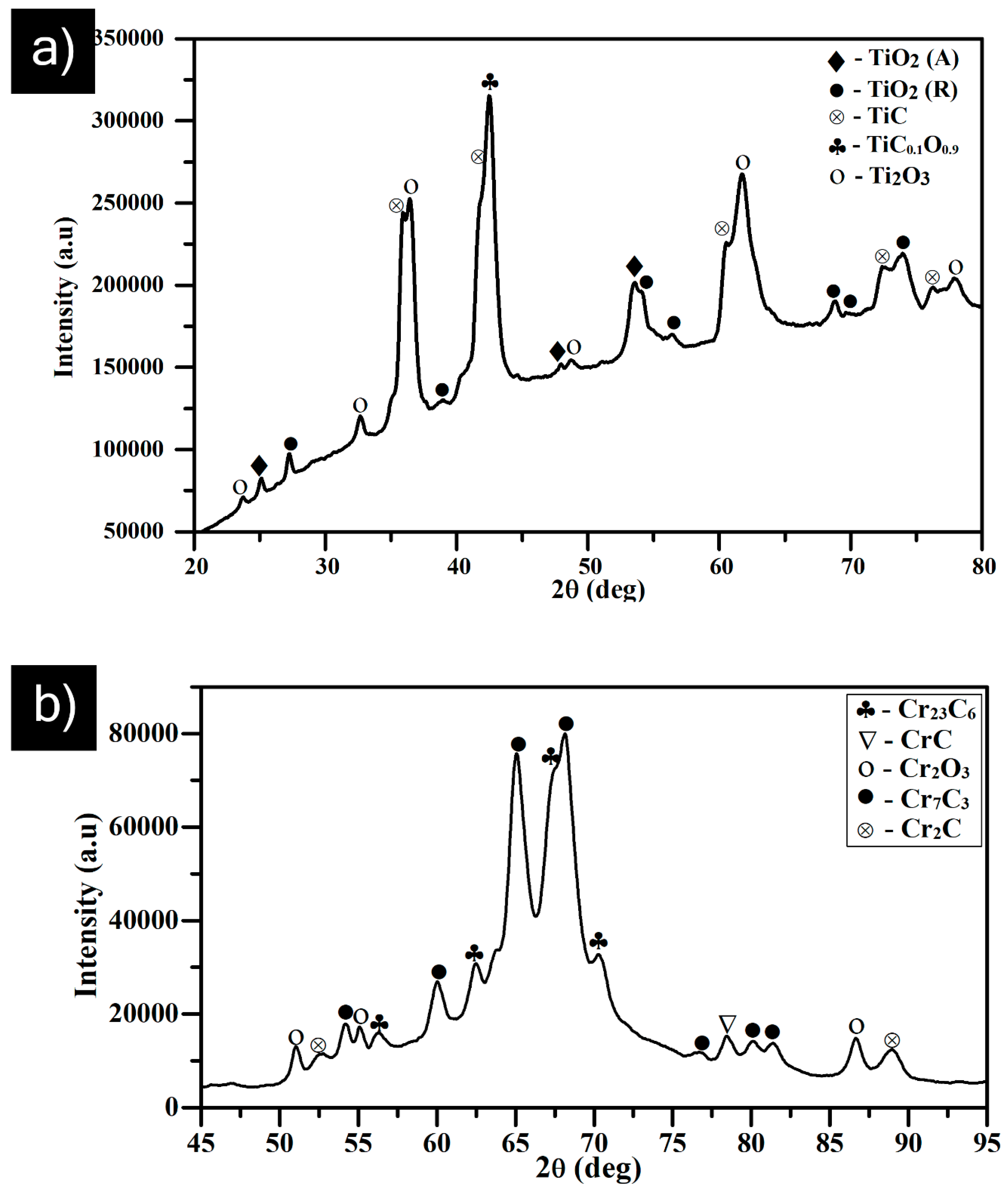
Phase analysis of both transition metal carbide coatings by micro-XRD revealed varying extents of oxidation and decarburization occurring in-flight, to show different levels of sub-carbides and oxides in
Figure 7a,b. Among various carbide materials, TiC is known for its difficulty in melting and is quite stable over a wide compositional range, between TiC
0.97 and TiC
0.50. It is highly challenging to retain the carbides during plasma spraying [
15,
16]. However, in the present case, the strongest peaks corresponded to titanium oxy-carbide and TiC phases (
Figure 7a). This implies minimal decarburization, although considerable amounts of titanium oxides were noted to have formed during the SPS deposition process. The predominant presence of carbide phases can potentially provide better wear resistance by reducing the friction coefficient between the sliding contacts, which was confirmed from the sliding wear results (
Table 2). Furthermore, the XRD pattern of the SPS TiC coating in
Figure 7a suggests that there could be some amorphous phase formation. Li et al. have reported similar findings related to amorphous phase content in tungsten-carbide-based coatings deposited by HVOF [
17].
Similarly, plasma/HVOF spraying of Cr
3C
2 typically results in phase transformation into Cr
7C
3 and Cr
23C
6. It has also been previously reported that Cr
7C
3 forms as a rim over Cr
3C
2 particles [
15]. On the other hand, the completely molten chromium carbide (melting point: 1811 °C [
14]) preferably precipitates in the form of stable M
23C
6-type carbides of Cr
23C
6, which are relatively smaller in grain size [
18]. Accordingly, Cr
7C
3 and Cr
23C
6 phases were detected in case of SPS Cr
3C
2 coatings along with non-stoichiometric CrC phases and oxides of chromium, as shown in
Figure 7b.
The TiC coating (12.9 ± 2.2 µm) showed a higher surface roughness (Ra) in as-sprayed condition than the Cr
3C
2 coating (4.6 ± 1.2 µm). It should be mentioned that the TiC feedstock had a relatively lower median particle size (D
50) and lower splat size in the as-sprayed condition than did Cr
3C
2. Furthermore, both the coatings were deposited using identical spray parameters. One possible explanation for the observed difference in Ra values could be the difference in the degree of in-flight melting of powder particles because of their vastly different melting temperatures. TiC (melting point: 3100 °C) has a higher melting temperature than Cr
3C
2 (melting point: 1800 °C), which could result in a higher degree of melting in the case of Cr
3C
2 than TiC. As discussed previously, some unmolten TiC particles were also noted in the coating, which could have contributed to higher surface roughness, suggesting need for further feedstock and process optimization. However, it is also pertinent to mention that the surface roughness of the SPS-processed Cr
3C
2 coating in this work was lower than that previously reported for HVOF-processed Cr
3C
2-based coating [
19]. For wear application, it is desirable to produce coatings with low surface roughness. Therefore, SPS seems to be a promising processing method to achieve coatings with low surface roughness due to its finer splats compared to APS, HVOF, etc.
The porosity content of both SPS processed carbide coatings was comparable and measured to be in the range of 6–9%, which is higher than ideally desired for wear applications. However, this preliminary attempt at depositing carbide coatings via SPS constitutes a useful basis to minimize porosity content and further improve coating quality through process optimization. The micro-hardness values for SPS-processed Cr
3C
2 (920 ± 70 HV
0.1) and TiC (980 ± 60 HV
0.1) coatings were found to be lower than the bulk hardness values for TiC (2850 HV
0.1) [
20] and Cr
3C
2 (1834 HV
0.1) specimens [
21,
22]. This could be attributed to the features such as pores and inter-splat boundaries that are typical of thermally sprayed coatings. Regardless of the above, the wear performance of these coatings was suggestive of considerable promise, as discussed below.
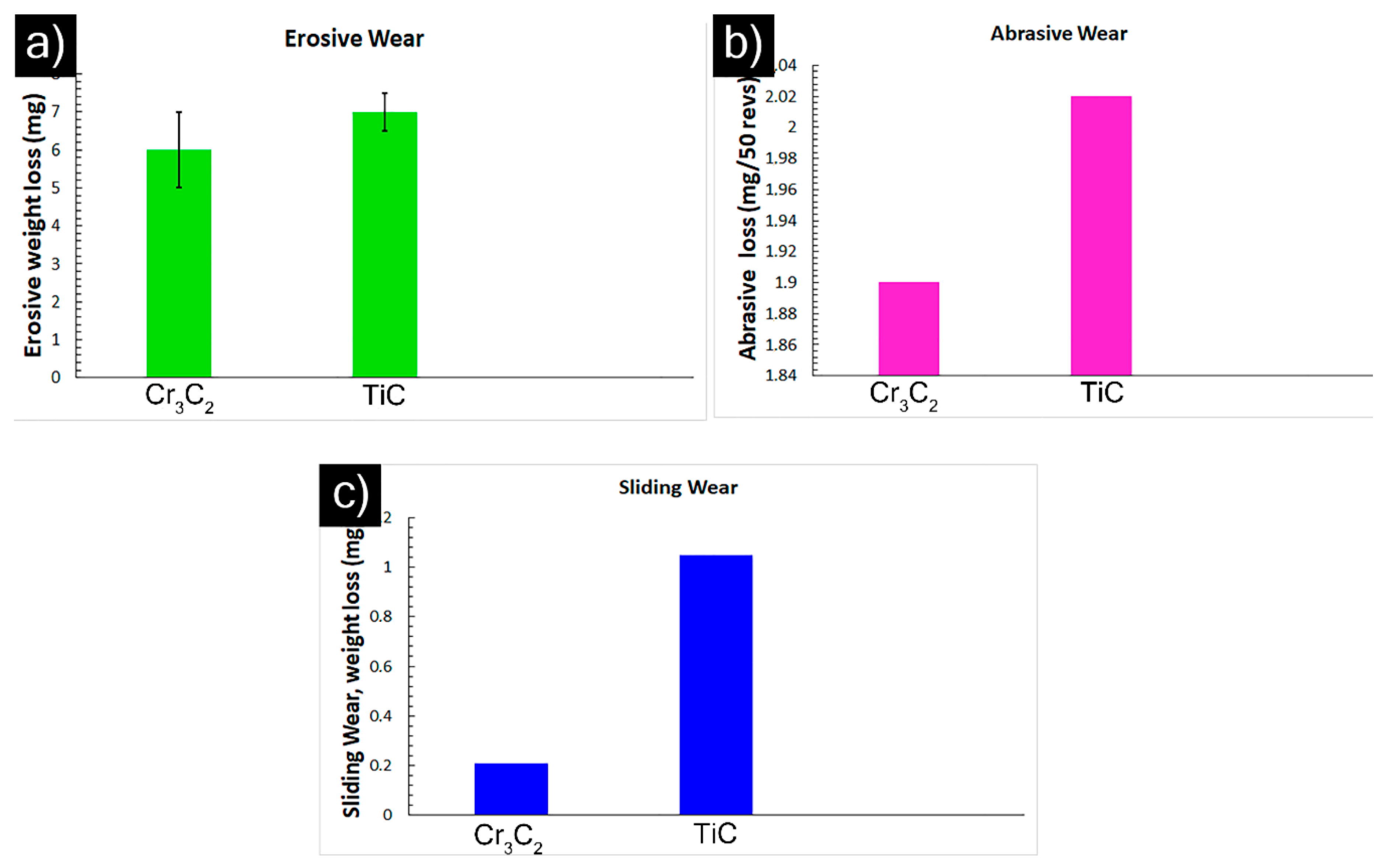
In the wear tests performed under identical test conditions, SPS-processed Cr
3C
2 showed superior erosive and sliding wear resistance to the SPS-processed TiC coating (
Figure 8a,c and
Table 2). However, the abrasion test results showed comparable performance for the investigated coatings, according to
Figure 8b. Note that the hardness for the TiC coating was higher than that of the Cr
3C
2 coating. Furthermore, the cross-sectional SEM micrograph of Cr
3C
2 showed few regions of poor cohesion between the splats. However, its erosion and sliding wear performance was superior to that of TiC. On the other hand, such fine-structured splats in the SPS-processed carbide coatings (in case of both Cr
3C
2 and TiC) could favor improved performance under all wear modes compared to a microstructure with relatively larger splats (APS) for an identical composition. Similar findings related to improved wear resistance compared to conventional coatings was reported by Liang et al. in the case of nanostructured coatings, and the reason was attributed to their enhanced mechanical properties (higher hardness, higher cohesive strength, higher toughness, etc.) [
23]. The above results from our preliminary study with carbide suspensions show considerable promise and clearly motivate further, more detailed, investigations. Process optimization and the investigation of different suspension properties (e.g., carbide particle size, solid loading, etc.) and their influence on wear behavior are logical next steps. Furthermore, examining the worn surfaces of the coatings and worn debris (for sliding wear) using SEM/EDS would provide further insights into the wear mechanisms responsible for material removal under different wear modes. These will be performed as a continuation of the present study.

 ,
, 


