A Study of Calcium-Silicate-Hydrate/Polymer Nanocomposites Fabricated Using the Layer-By-Layer Method


Abstract
:1. Introduction
2. Experiments
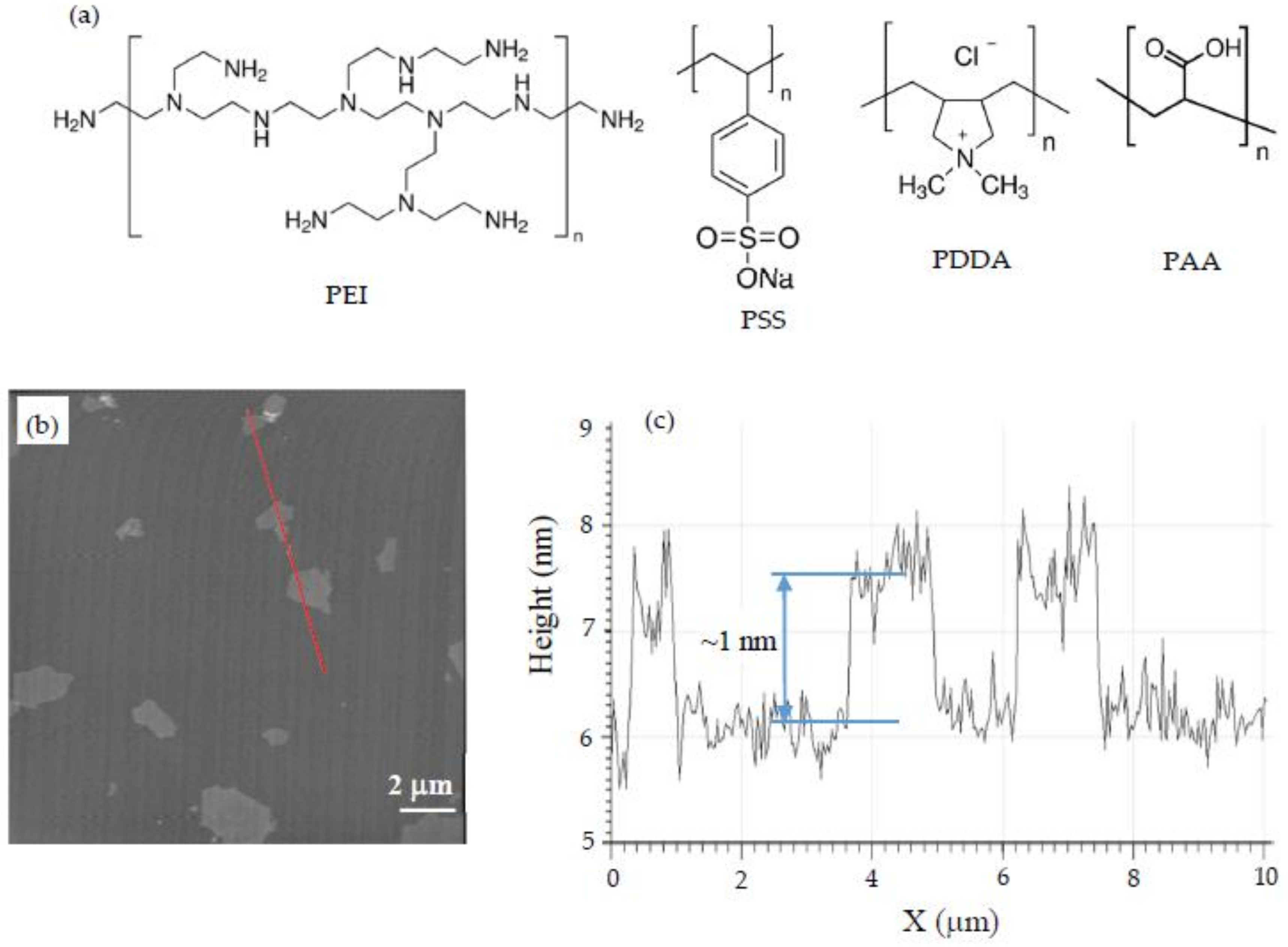
2.1. Materials
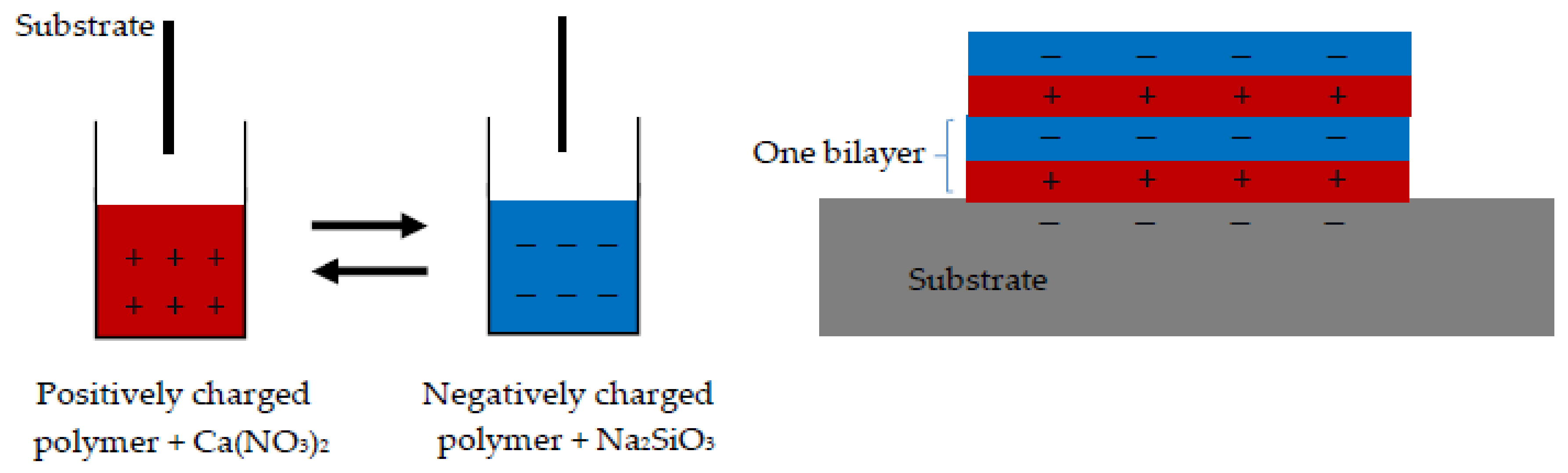
2.2. Sample Preparation
2.3. AFM Imaging
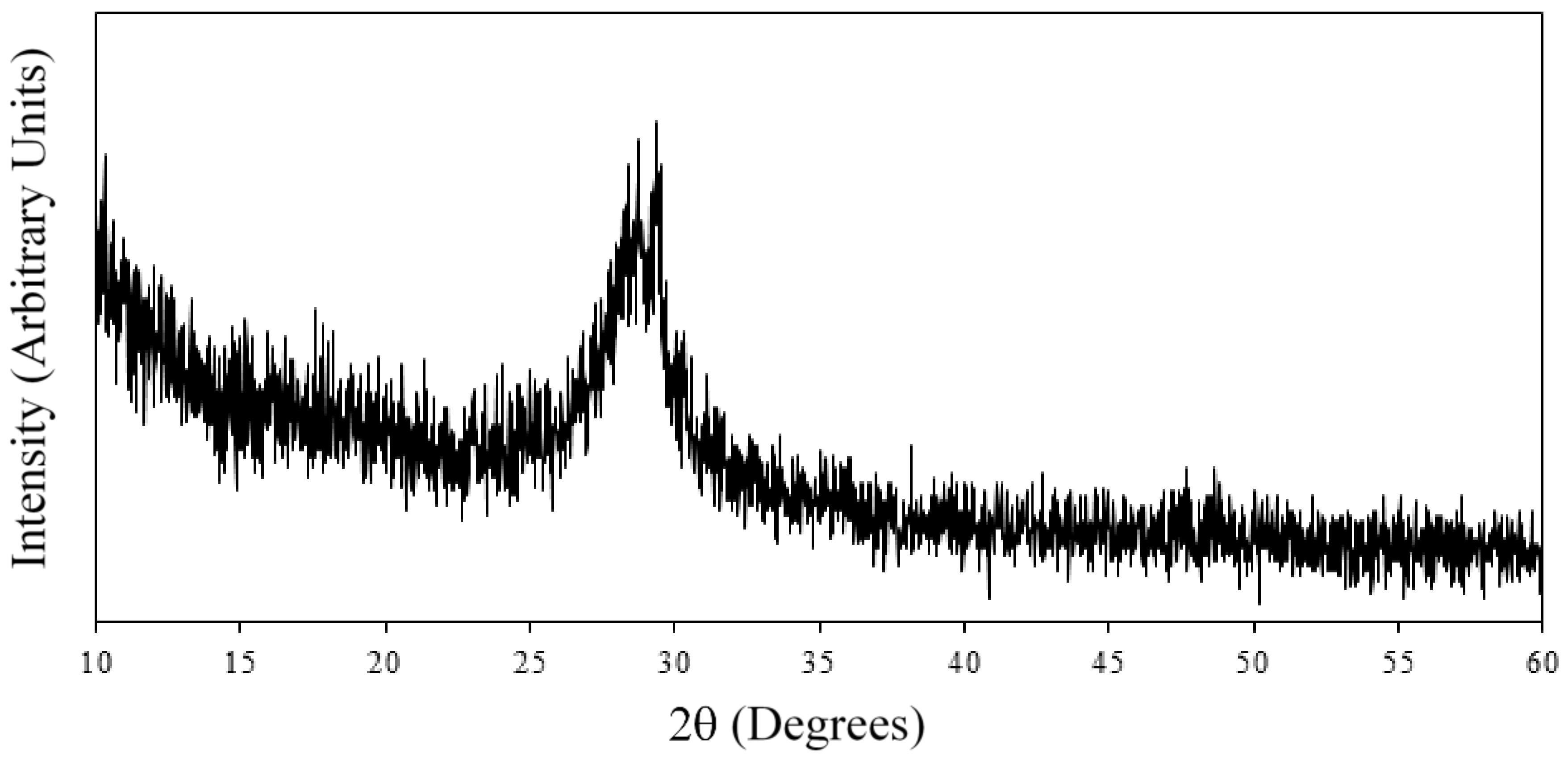
2.4. X-ray Diffraction (XRD)
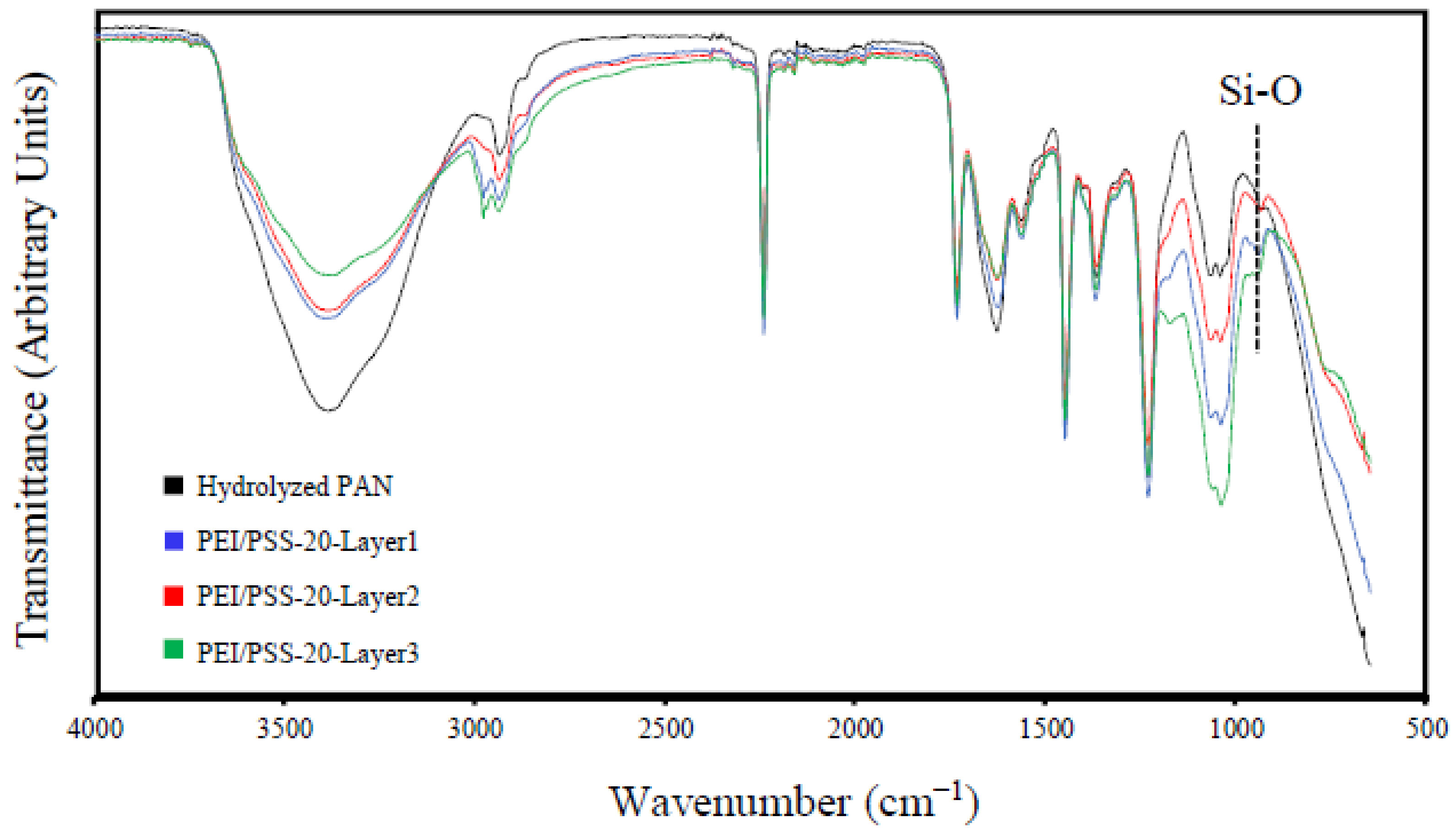
2.5. Fourier Transform Infrared Spectroscopy
2.6. Zeta Potential Measurement
2.7. AFM Nanoindentation
3. Results and Discussion
3.1. Characterization
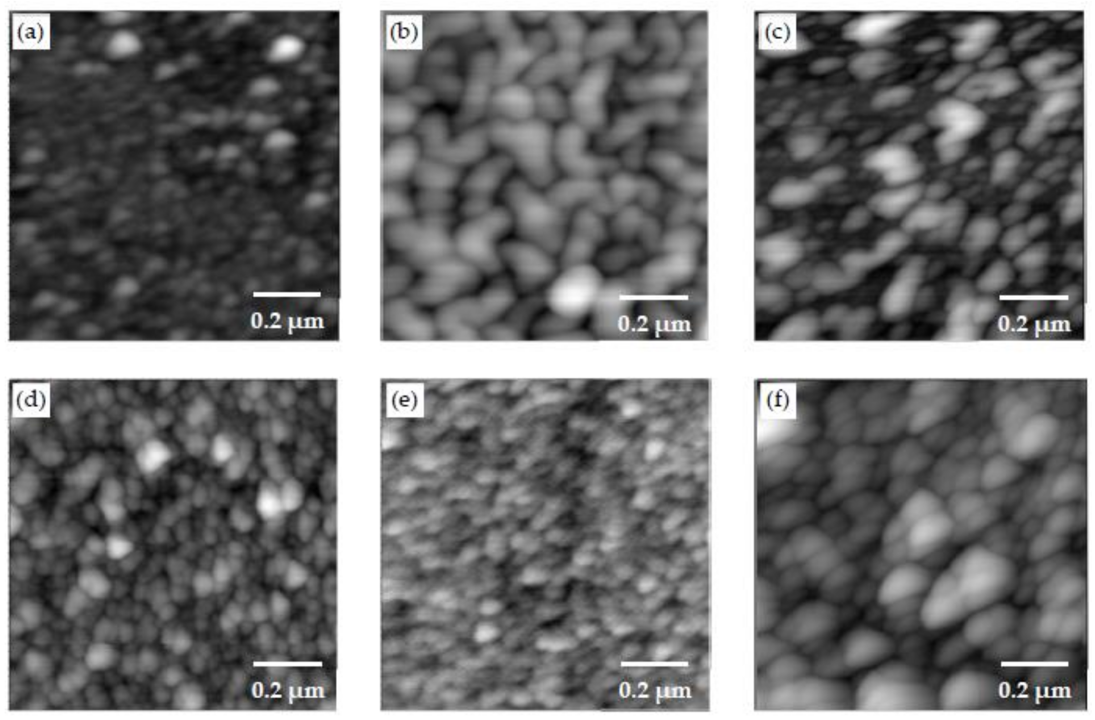
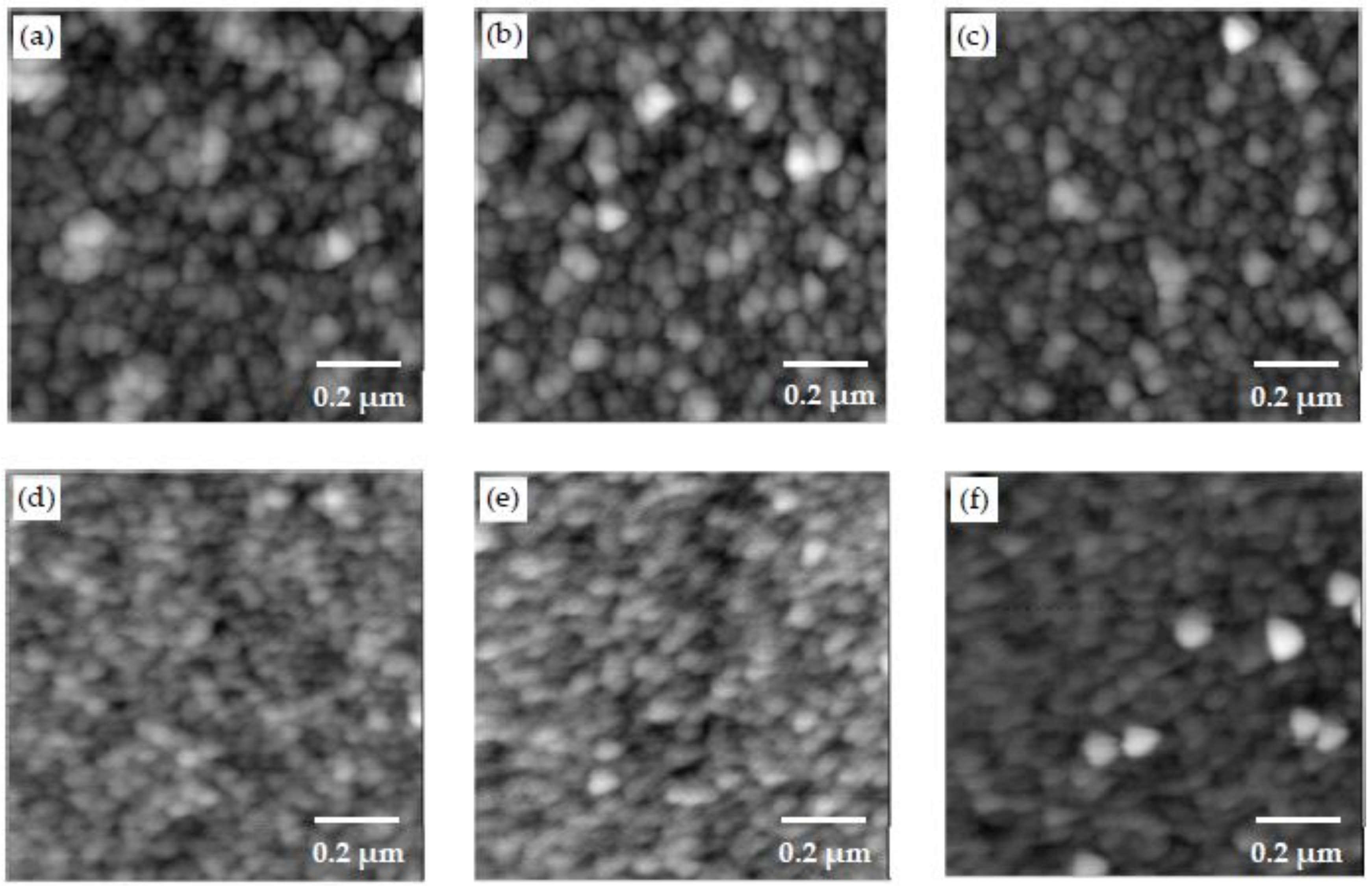
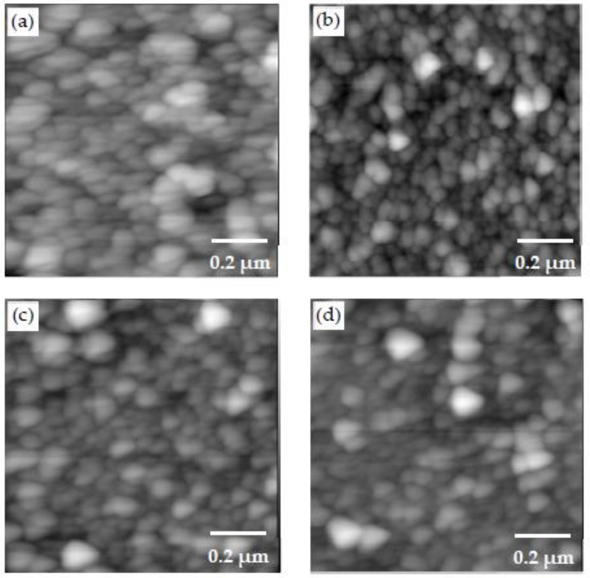
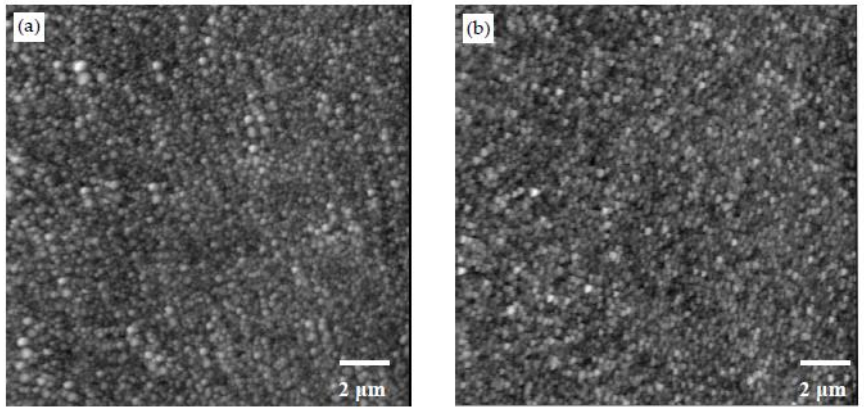
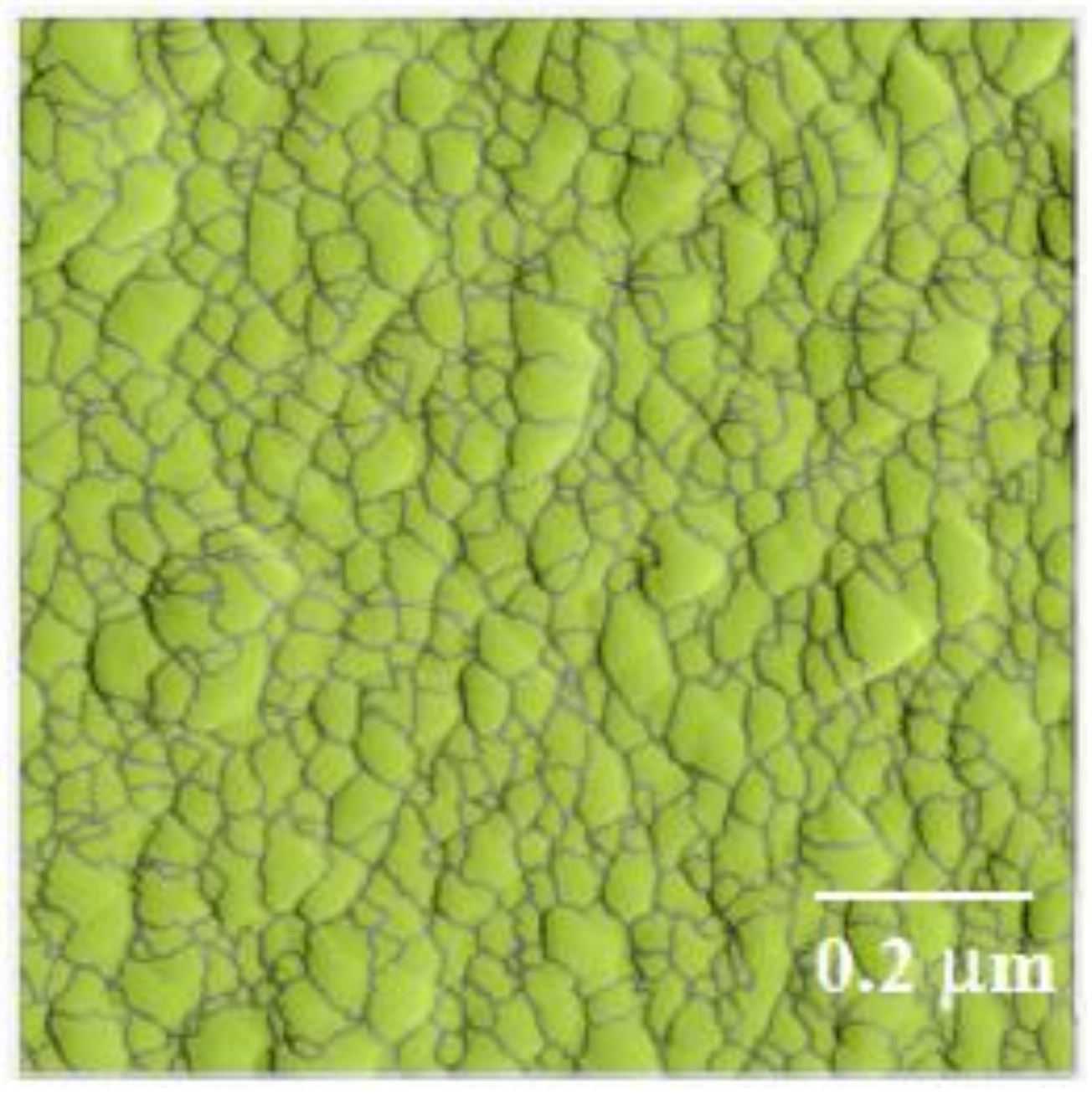
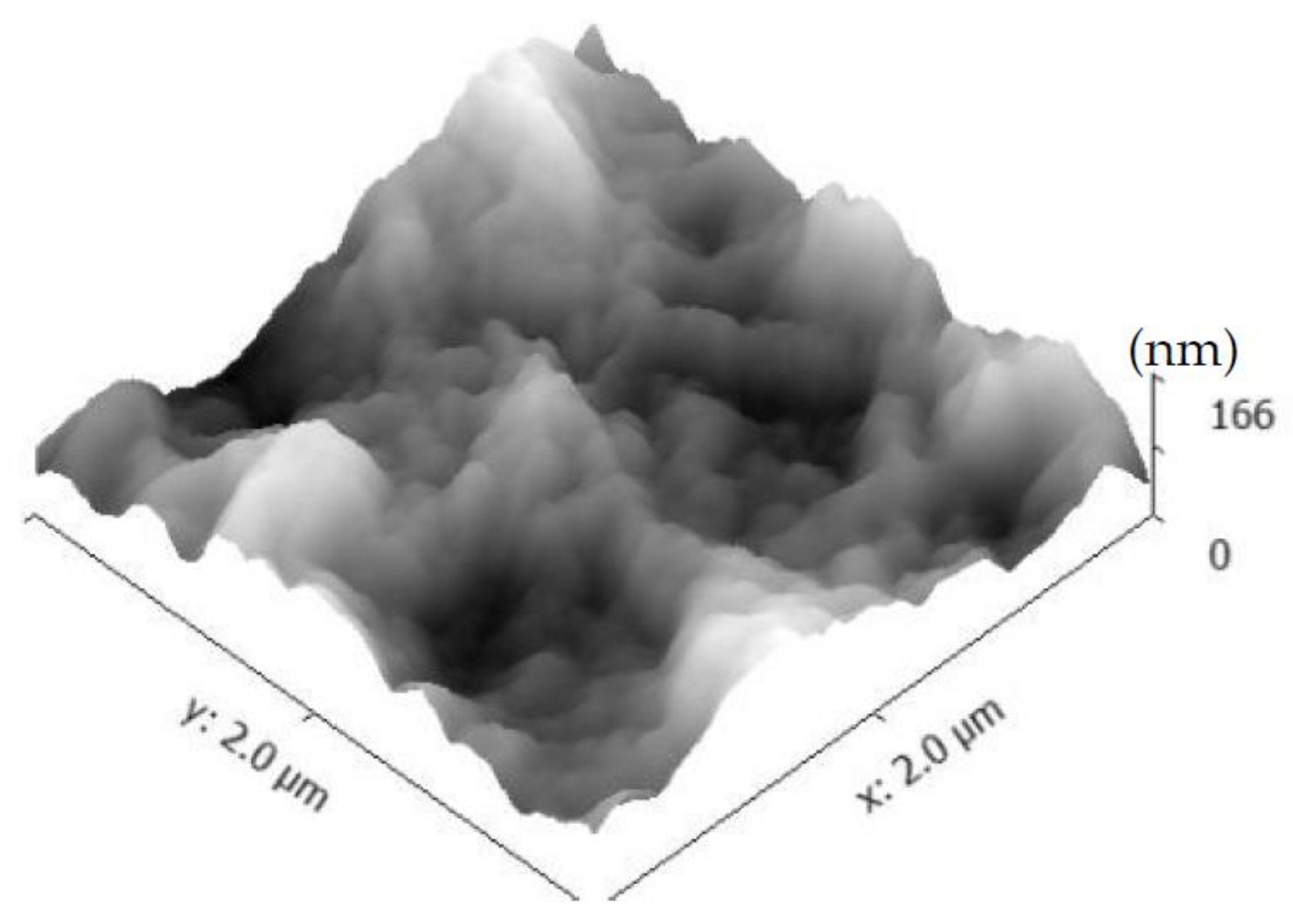
3.2. Morphology Examination
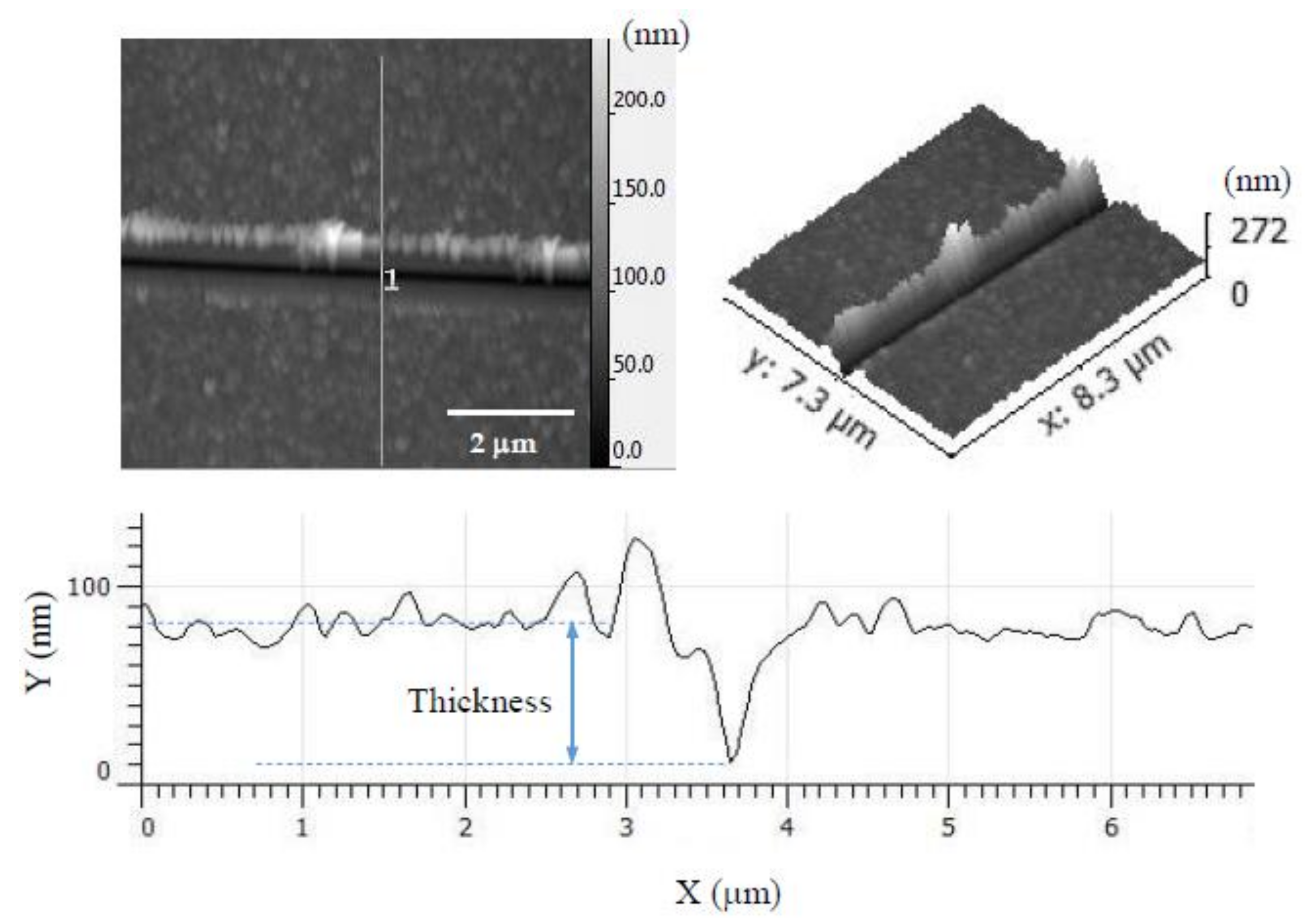
3.3. AFM Nanoindentation
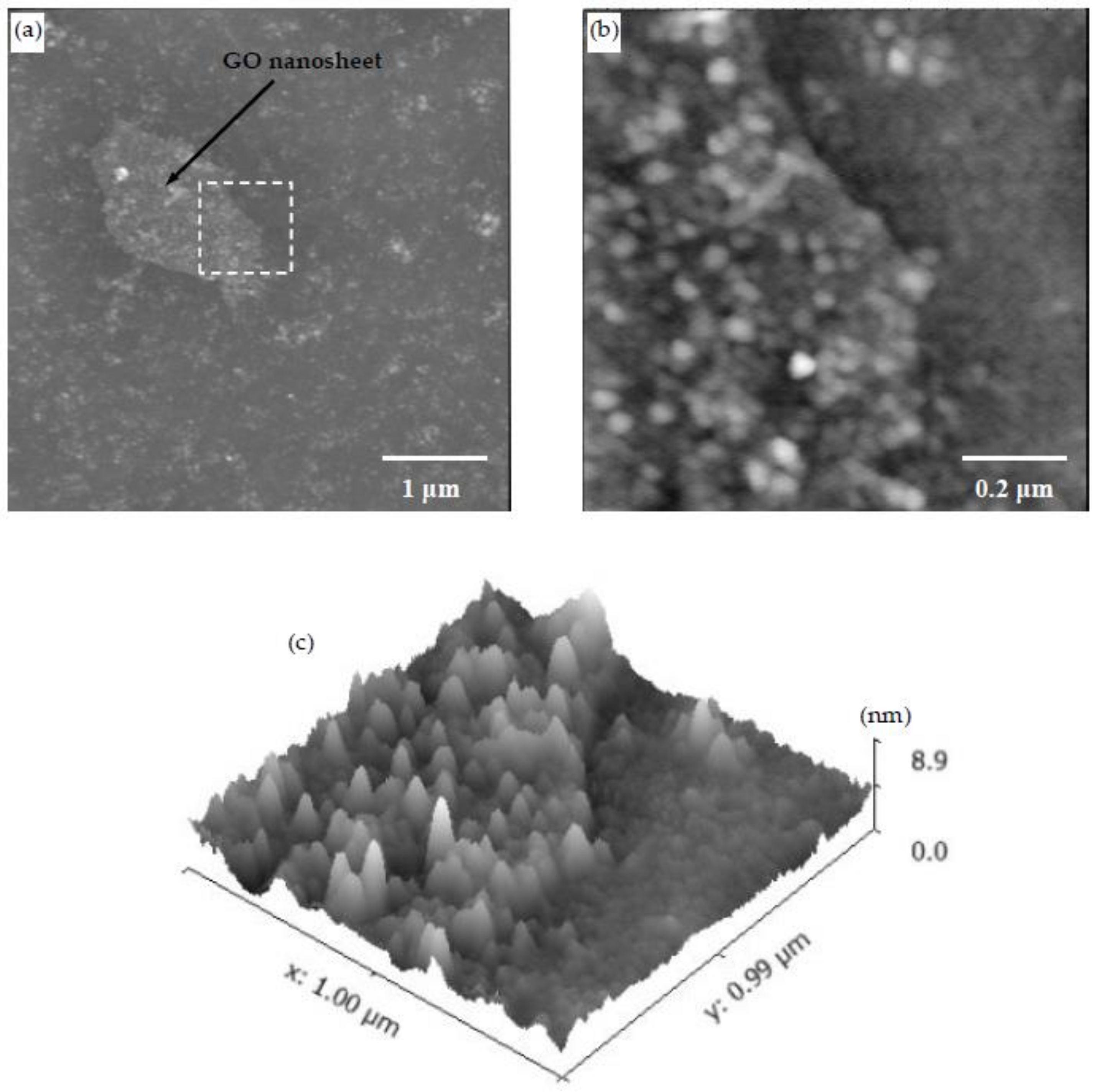
3.4. CSH/Polymer/GO Nanocomposite
4. Conclusions
- Different morphologies were observed in samples made with different polymers, and this indicated the potential influence of polymers on the microstructure of CSH/polymer nanocomposites.
- An increase in the pH level was shown to result in samples with higher roughness and larger CSH particles.
- The change in C/S ratio in the range examined in this study did not appear to show a noticeable effect on the morphology of CSH/polymer fabricated by the LBL method. Further investigations are necessary to provide more insights into the effect of C/S.
- The Young’s modulus of CSH/polymer nanocomposites obtained from AFM nanoindentation was measured to be in the range of the Young’s modulus values of powder CSH/polymer reported in the literature [8,11]. In spite of observed differences in the morphology of PEI/PSS-CSH and PDDA/PAA-CSH, the nanoscale Young’s modulus of these nanocomposites did not exhibit significant differences.
- It was shown that GO nanosheets seemed to increase the nucleation of CSH particles as inferred from the higher density of CSH particles on a GO nanosheet compared to regions outside of the GO nanosheet.
Acknowledgments
Author Contributions
Conflicts of Interest
References
- Tong, T.; Fan, Z.; Liu, Q.; Wang, S.; Tan, S.; Yu, Q. Investigation of the effects of graphene and graphene oxide nanoplatelets on the micro- and macro-properties of cementitious materials. Constr. Build. Mater. 2016, 106, 102–114. [Google Scholar] [CrossRef]
- Raki, L.; Beaudoin, J.; Alizadeh, R.; Makar, J.; Sato, T. Cement and Concrete Nanoscience and Nanotechnology. Materials (Basel) 2010, 3, 918–942. [Google Scholar] [CrossRef]
- Alizadeh, R.; Beaudoin, J.J.; Raki, L. Mechanical properties of calcium silicate hydrates. Mater. Struct. 2011, 44, 13–28. [Google Scholar] [CrossRef]
- Pellenq, R.J.M.; Lequeux, N.; van Damme, H. Engineering the bonding scheme in C-S-H: The iono-covalent framework. Cem. Concr. Res. 2008, 38, 159–174. [Google Scholar] [CrossRef]
- Jones, C.A.; Grasley, Z.C.; Ohlhausen, J.A. Measurement of elastic properties of calcium silicate hydrate with atomic force microscopy. Cem. Concr. Compos. 2012, 34, 468–477. [Google Scholar] [CrossRef]
- Nonat, A. The structure and stoichiometry of C-S-H. Cem. Concr. Res. 2004, 34, 1521–1528. [Google Scholar] [CrossRef]
- Matsuyama, H.; Young, J.F. Intercalation of Polymers in Calcium Silicate Hydrate: A New Synthetic Approach to Biocomposites? Chem. Mater. 1999, 11, 16–19. [Google Scholar] [CrossRef]
- Pelisser, F.; Gleize, P.J.P.; Peterson, M. Synthesis of calcium silicate hydrate/polymer complexes: Part I. Anionic and nonanionic polymers. J. Mater. Res. 1999, 14, 3379–3388. [Google Scholar]
- Matsuyama, H.; Young, J.F. Synthesis of calcium silicate hydrate/polymer complexes: Part II. Cationic polymers and complex formation with different polymers. J. Mater. Res. 1999, 14, 3389–3396. [Google Scholar] [CrossRef]
- Mojumdar, S.C.; Raki, L. Preparation and properties of calcium silicate hydrate-poly(vinyl alcohol) nanocomposite materials. J. Therm. Anal. Calorim. 2005, 82, 89–95. [Google Scholar] [CrossRef]
- Pelisser, F.; Gleize, P.J.P.; Mikowski, A. Effect of poly(diallyldimethylammonium chloride) on nanostructure and mechanical properties of calcium silicate hydrate. Mater. Sci. Eng. A 2010, 527, 7045–7049. [Google Scholar] [CrossRef]
- Alizadeh, R.; Beaudoin, J.J.; Raki, L.; Terskikh, V. C–S–H/polyaniline nanocomposites prepared by in situ polymerization. J. Mater. Sci. 2010, 46, 460–467. [Google Scholar] [CrossRef]
- Merlin, F.; Lombois, H.; Joly, S.; Lequeux, N.; Halary, J.-L.; van Damme, H. Cement-polymer and clay-polymer nano- and meso-composites: Spotting the difference. J. Mater. Chem. 2002, 12, 3308–3315. [Google Scholar] [CrossRef]
- Khoshnazar, R.; Beaudoin, J.J.; Raki, L.; Alizadeh, R. Interaction of 2-, 3- and 4-nitrobenzoic acid with the structure of calcium-silicate-hydrate. Mater. Struct. 2014, 49, 499–506. [Google Scholar] [CrossRef]
- Pelisser, F.; Gleize, P.J.P.; Mikowski, A. Structure and micro-nanomechanical characterization of synthetic calcium-silicate-hydrate with Poly(Vinyl Alcohol). Cem. Concr. Compos. 2014, 48, 1–8. [Google Scholar] [CrossRef]
- Tang, Z.; Kotov, N.A.; Magonov, S.; Ozturk, B. Nanostructured artificial nacre. Nat. Mater. 2003, 2, 413–418. [Google Scholar] [CrossRef] [PubMed]
- Das, P.; Walther, A. Ionic supramolecular bonds preserve mechanical properties and enable synergetic performance at high humidity in water-borne, self-assembled nacre-mimetics. Nanoscale 2013, 5, 9348. [Google Scholar] [CrossRef] [PubMed]
- Minet, J.; Abramson, S.; Bresson, B.; Franceschini, A.; van Damme, H.; Lequeux, N. Organic calcium silicate hydrate hybrids: A new approach to cement based nanocomposites. J. Mater. Chem. 2006, 16, 1379. [Google Scholar] [CrossRef]
- Minet, J.; Abramson, S.; Bresson, B.; Sanchez, C.; Montouillout, V.; Lequeux, N. New layered calcium organosilicate hybrids with covalently linked organic functionalities. Chem. Mater. 2004, 16, 3955–3962. [Google Scholar] [CrossRef]
- Khoshnazar, R.; Beaudoin, J.J.; Raki, L.; Alizadeh, R. Durability and mechanical properties of C-S-H/nitrobenzoic acid composite systems. Mater. Struct. 2016, 49, 5315–5325. [Google Scholar] [CrossRef]
- Khoshnazar, R.; Beaudoin, J.J.; Raki, L.; Alizadeh, R. Characteristics and Engineering Performance of C-S-H/Aminobenzoic Acid Composite Systems. J. Adv. Concr. Technol. 2015, 13, 415–420. [Google Scholar] [CrossRef]
- Li, Y.; Liu, F.; Sun, J. A facile layer-by-layer deposition process for the fabrication of highly transparent superhydrophobic coatings. Chem. Commun. 2009, 19, 2730–2732. [Google Scholar] [CrossRef] [PubMed]
- Xu, J.; Wang, Z.; Wen, L.; Zhou, X.; Xu, J.; Yang, S. Dynamics of the layer-by-layer assembly of a poly(acrylic acid)–lanthanide complex colloid and poly(diallyldimethyl ammonium). Soft Matter 2016, 12, 867–875. [Google Scholar] [CrossRef] [PubMed]
- Zhang, L.; Li, Y.; Sun, J.; Shen, J. Mechanically stable antireflection and antifogging coatings fabricated by the layer-by-layer deposition process and postcalcination. Langmuir 2008, 24, 10851–10857. [Google Scholar] [CrossRef] [PubMed]
- Guo, H.; Ma, Y.; Sun, P.; Cui, S.; Qin, Z.; Liang, Y. Self-cleaning and antifouling nanofiltration membranes—superhydrophilic multilayered polyelectrolyte/CSH composite films towards rejection of dyes. RSC Adv. 2015, 5, 63429–63438. [Google Scholar] [CrossRef]
- Guo, H.; Sun, P.; Liang, Y.; Ma, Y.; Qin, Z.; Cui, S. In-situ fabrication of polyelectrolyte-CSH superhydrophilic coatings via layer-by-layer assembly. Chem. Eng. J. 2014, 253, 198–206. [Google Scholar] [CrossRef]
- Tang, Z.; Wang, Y.; Podsiadlo, P.; Kotov, N.A. Biomedical applications of layer-by-layer assembly: From biomimetics to tissue engineering. Adv. Mater. 2006, 18, 3203–3224. [Google Scholar] [CrossRef]
- Ariga, K.; Hill, J.P.; Ji, Q. Layer-by-layer assembly as a versatile bottom-up nanofabrication technique for exploratory research and realistic application. Phys. Chem. Chem. Phys. 2007, 9, 2319–2340. [Google Scholar] [CrossRef] [PubMed]
- Xiao, F.-X.; Pagliaro, M.; Xu, Y.-J.; Liu, B. Layer-by-layer assembly of versatile nanoarchitectures with diverse dimensionality: A new perspective for rational construction of multilayer assemblies. Chem. Soc. Rev. 2016, 45. [Google Scholar] [CrossRef] [PubMed]
- Fou, A.C.; Onitsuka, O.; Ferreira, M.; Rubner, M.F.; Hsieh, B.R. Fabrication and properties of light-emitting diodes based on self-assembled multilayers of poly(phenylene vinylene). J. Appl. Phys. 1996, 79, 7501. [Google Scholar] [CrossRef]
- Cheung, J.H.; Stockton, W.B.; Rubner, M.F. Molecular-Level Processing of Conjugated Polymers. 3. Layer-by-Layer Manipulation of Polyaniline via Electrostatic Interactions. Macromolecules 1997, 30, 2712–2716. [Google Scholar] [CrossRef]
- Lvov, Y.; Yamada, S.; Kunitake, T. Non-linear optical effects in layer-by-layer alternate films of polycations and an azobenzene-containing polyanion. Thin Solid Films 1997, 300, 107–112. [Google Scholar] [CrossRef]
- Liu, S.; Montazami, R.; Liu, Y.; Jain, V.; Lin, M.; Heflin, J.R.; Zhang, Q.M. Layer-by-layer self-assembled conductor network composites in ionic polymer metal composite actuators with high strain response. Appl. Phys. Lett. 2009, 95, 023505. [Google Scholar] [CrossRef]
- Khopade, A.J.; Caruso, F. Surface-modification of polyelectrolyte multilayer-coated particles for biological applications. Langmuir 2003, 19, 6219–6225. [Google Scholar] [CrossRef]
- Tong, W.; Song, X.; Gao, C. Layer-by-layer assembly of microcapsules and their biomedical applications. Chem. Soc. Rev. 2012, 41, 6103–6124. [Google Scholar] [CrossRef] [PubMed]
- Kim, B.S.; Choi, J.W. Polyelectrolyte multilayer microcapsules: Self-assembly and toward biomedical applications, Biotechnol. Bioprocess Eng. 2007, 12, 323–332. [Google Scholar] [CrossRef]
- Shukla, A.; Almeida, B. Advances in cellular and tissue engineering using layer-by-layer assembly, Wiley Interdiscip. Rev. Nanomed. Nanobiotechnol. 2014, 6, 411–421. [Google Scholar] [CrossRef] [PubMed]
- Guduric, V.; Metz, C.; Siadous, R.; Bareille, R.; Levato, R.; Engel, E.; Fricain, J.C.; Devillard, R.; Luzanin, O.; Catros, S. Layer-by-layer bioassembly of cellularized polylactic acid porous membranes for bone tissue engineering. J. Mater. Sci. Mater. Med. 2017, 28, 78. [Google Scholar] [CrossRef] [PubMed]
- Lee, T.; Min, S.H.; Gu, M.; Jung, Y.K.; Lee, W.; Lee, J.U.; Seong, D.G.; Kim, B. Layer-by-Layer Assembly for Graphene-Based Multilayer Nanocomposites: Synthesis and Applications. Chem. Mater. 2015, 27, 3785–3796. [Google Scholar] [CrossRef]
- Babak, F.; Abolfazl, H.; Alimorad, R.; Parviz, G. Preparation and Mechanical Properties of Graphene Oxide: Cement Nanocomposites. Sci. World J. 2014, 2014. [Google Scholar] [CrossRef] [PubMed]
- Lv, S.; Ma, Y.; Qiu, C.; Sun, T.; Liu, J.; Zhou, Q. Effect of graphene oxide nanosheets of microstructure and mechanical properties of cement composites. Constr. Build. Mater. 2013, 49, 121–127. [Google Scholar] [CrossRef]
- Alkhateb, H.; Al-Ostaz, A.; Cheng, D.A.H.; Li, X. Materials Genome for Graphene-Cement Nanocomposites. J. Nanomech. Micromech. 2013, 3, 67–77. [Google Scholar] [CrossRef]
- Sedaghat, A.; Ram, M.K.; Zayed, A.; Kamal, R.; Shanahan, N. Investigation of Physical Properties of Graphene-Cement Composite for Structural Applications. Open J. Compos. Mater. 2014, 4, 12–21. [Google Scholar] [CrossRef]
- Li, W.; Li, X.; Chen, S.J.; Long, G.; Liu, Y.M.; Duan, W.H. Effects of nanoalumina and graphene oxide on early-age hydration and mechanical properties of cement paste. J. Mater. Civ. Eng. 2017, 29, 1–9. [Google Scholar] [CrossRef]
- Cheng, Y.; Xu, C.; Shen, P.K.; Jiang, S.P. Effect of nitrogen-containing functionalization on the electrocatalytic activity of PtRu nanoparticles supported on carbon nanotubes for direct methanol fuel cells. Appl. Catal. B Environ. 2014, 158–159, 140–149. [Google Scholar] [CrossRef]
- Sigma-Aldrich. Available online: www.sigmaaldrich.com (accessed on 15 March 2018).
- Hertz, H. On the contact of elastic solids. J. Reine Angew. Math. 1881, 92, 156–171. [Google Scholar]
- Grangeon, S.; Claret, F.; Linard, Y.; Chiaberge, C. X-ray diffraction: A powerful tool to probe and understand the structure of nanocrystalline calcium silicate hydrates. Acta Crystallogr. Sect. B Struct. Sci. Cryst. Eng. Mater. 2013, 69, 465–473. [Google Scholar] [CrossRef] [PubMed]
- Grangeon, S.; Claret, F.; Roosz, C.; Sato, T.; Gaboreau, S.; Linard, Y. Structure of Nanocrystalline Calcium Silicate Hydrates: Insights from X-Ray Diffraction, Synchrotron X-Ray Absorption and Nuclear Magnetic Resonance. J. Appl. Crystallogr. 2016, 49, 771–783. [Google Scholar] [CrossRef] [PubMed]
- Yu, P.; Kirkpatrick, R.J.; Poe, B.; McMillan, P.F.; Cong, X. Structure of calcium silicate hydrate (C-S-H): Near-, mid-, and far-infrared spectroscopy. J. Am. Ceram. Soc. 1999, 82, 742–748. [Google Scholar] [CrossRef]
- Dev, V.R.G.; Venugopal, J.R.; Senthilkumar, M.; Gupta, D.; Ramakrishna, S. Prediction of Water Retention Capacity of Hydrolysed Electrospun Polyacrylonitrile Fibers Using Statistical Model and Artificial Neural Network. J. Appl. Polym. Sci. 2013, 113, 3397–3405. [Google Scholar]
- Zhang, J.; Lu, Z.; Wu, M.; Wu, Q.; Yang, J. Facile fabrication of poly(acrylic acid) hollow nanogels via in situ Pickering miniemulsion polymerization. Polym. Chem. 2015, 6, 6125–6128. [Google Scholar] [CrossRef]
- Shiratori, S.S.; Rubner, M.F. PH-Dependent Thickness Behavior of Sequentially Adsorbed Layers of Weak Polyelectrolytes. Macromolecules 2000, 33, 4213–4219. [Google Scholar] [CrossRef]
- Nečas, D.; Klapetek, P. Gwyddion: An Open-Source Software for SPM Data Analysis. Open Phys. 2012, 10, 181–188. [Google Scholar] [CrossRef]
- Wilson John, Synthesis, Properties and Analysis of PolyDADMAC for Water Purification. Ph.D. Thesis, Stellenbosch University, Stellenbosch, South Africa, 2008.
- Matsuyama, H.; Young, J.F. Effects of pH on Precipitation of Quasi-Crystalline Calcium Silicate Hydrate in Aqueous Solution. Adv. Cem. Res. 2000, 12, 29–33. [Google Scholar] [CrossRef]
- Picker, A. Influence of Polymers on Nucleation and Assembly of Calcium Silicate Hydrates. Ph.D. Thesis, University of Konstanz, Konstanz, Germany, 2013. [Google Scholar]
- Delhorme, M.; Labbez, C.; Turesson, M.; Lesniewska, E.; Woodward, C.E.; Jönsson, B. Aggregation of Calcium Silicate Hydrate Nanoplatelets. Langmuir 2016, 32, 2058–2066. [Google Scholar] [CrossRef] [PubMed]
- Pelisser, F.; Jean, P.; Gleize, P.; Mikowski, A. Effect of the Ca/Si Molar Ratio on the Micro/nanomechanical Properties of Synthetic C-S-H Measured by Nanoindentation. J. Phys. Chem. C 2012, 116, 17219–17227. [Google Scholar] [CrossRef]
- Milton, G.W. The Theory of Composites; Cambridge University Press: Cambridge, UK, 2002. [Google Scholar]
- Kim, J.J.; Foley, E.M.; Reda Taha, M.M. Nano-mechanical characterization of synthetic calcium-silicate-hydrate (C-S-H) with varying CaO/SiO2 mixture ratios. Cem. Concr. Compos. 2013, 36, 65–70. [Google Scholar] [CrossRef]


| Solution | pH | Zeta Potential (mV) | Size (nm) |
|---|---|---|---|
| PEI-Ca2+ | 10.5 | 10.0 | 85.7 |
| PSS-SO32− | 11.7 | −42.9 | 63.4 |
| PEI/PSS | 10.5 | −28.3 | 60.9 |
| PEI/PSS-CSH | 10.8 | −39.3 | 205.0 |
| PDDA-Ca2+ | 8.7 | 44.0 | 482.7 |
| PAA-SO32− | 11.5 | −53.5 | 20.1 |
| PDDA/PAA | 2.9 | 70.4 | 323.9 |
| PDDA/PAA-CSH | 10.1 | −15.4 |
| Sample Label | Ra (nm) 5 μm by 5 μm | Ra (nm) 1 μm by 1 μm |
|---|---|---|
| PEI/PSS | 1.47 | 1.18 |
| PEI/PSS-CSH | 4.77 | 4.1 |
| PDDA/PAA | 7.95 | 6.85 |
| PDDA/PAA-CSH | 0.85 | 0.873 |
| PEI/PAA | 8.12 | 9.75 |
| PEI/PAA-CSH | 23.2 | 19.7 |
| Sample Label | Ra (nm) 5 μm by 5 μm | Ra (nm) 1 μm by 1 μm | Number of Particles 1 μm by 1 μm | Mean Area of the Particles (nm2) |
|---|---|---|---|---|
| PEI/PSS-CSH(10) | 7.5 | 6.13 | 720 | 1000 |
| PEI/PSS-CSH | 4.77 | 4.1 | 770 | 980 |
| PEI/PSS-CSH(40) | 4.42 | 3.82 | 791 | 950 |
| PDDA/PAA-CSH(10) | 1.03 | 1 | 640 | 1190 |
| PDDA/PAA-CSH | 0.85 | 0.873 | 678 | 1110 |
| PDDA/PAA-CSH(40) | 0.91 | 0.99 | 709 | 1060 |
| Sample Label | Ra (nm) 5 μm by 5 μm | Ra (nm) 1 μm by 1 μm | Number of Particles 1 μm by 1 μm | Mean Area of the Particles (nm2) |
|---|---|---|---|---|
| PDDA/PAA-CSH | 0.85 | 0.873 | 678 | 1110 |
| PDDA/PAA-CSH-HighpH | 1.46 | 1.39 | 394 | 2060 |
| Sample Label | Ra (nm) 5 μm by 5 μm | Ra (nm) 1 μm by 1 μm | Number of Particles 1 μm by 1 μm | Mean Area of the Particles (nm2) |
|---|---|---|---|---|
| PEI/PSS-CSH-0.7 | 4.42 | 4.33 | 800 | 980 |
| PEI/PSS-CSH | 4.77 | 4.1 | 770 | 980 |
| PEI/PSS-CSH-1.5 | 4.35 | 4.08 | 717 | 1060 |
| PEI/PSS-CSH-2.3 | 4.00 | 4.03 | 711 | 1070 |
| Sample Label | E (GPa) Before Heat Treatment | Thickness (nm) | E (GPa) After Heat Treatment | Thickness (nm) |
|---|---|---|---|---|
| PEI/PSS-CSH | 10.9 | 200 | 14.3 | 80 |
| PDDA/PAA-CSH | 11.9 | 180 | 11.0 | 80 |
© 2018 by the authors. Licensee MDPI, Basel, Switzerland. This article is an open access article distributed under the terms and conditions of the Creative Commons Attribution (CC BY) license (http://creativecommons.org/licenses/by/4.0/).
Share and Cite
Kamali, M.; Ghahremaninezhad, A. A Study of Calcium-Silicate-Hydrate/Polymer Nanocomposites Fabricated Using the Layer-By-Layer Method. Materials 2018, 11, 527. https://doi.org/10.3390/ma11040527
Kamali M, Ghahremaninezhad A. A Study of Calcium-Silicate-Hydrate/Polymer Nanocomposites Fabricated Using the Layer-By-Layer Method. Materials. 2018; 11(4):527. https://doi.org/10.3390/ma11040527
Chicago/Turabian StyleKamali, Mahsa, and Ali Ghahremaninezhad. 2018. "A Study of Calcium-Silicate-Hydrate/Polymer Nanocomposites Fabricated Using the Layer-By-Layer Method" Materials 11, no. 4: 527. https://doi.org/10.3390/ma11040527
APA StyleKamali, M., & Ghahremaninezhad, A. (2018). A Study of Calcium-Silicate-Hydrate/Polymer Nanocomposites Fabricated Using the Layer-By-Layer Method. Materials, 11(4), 527. https://doi.org/10.3390/ma11040527