3.1. Preparation Mechanism
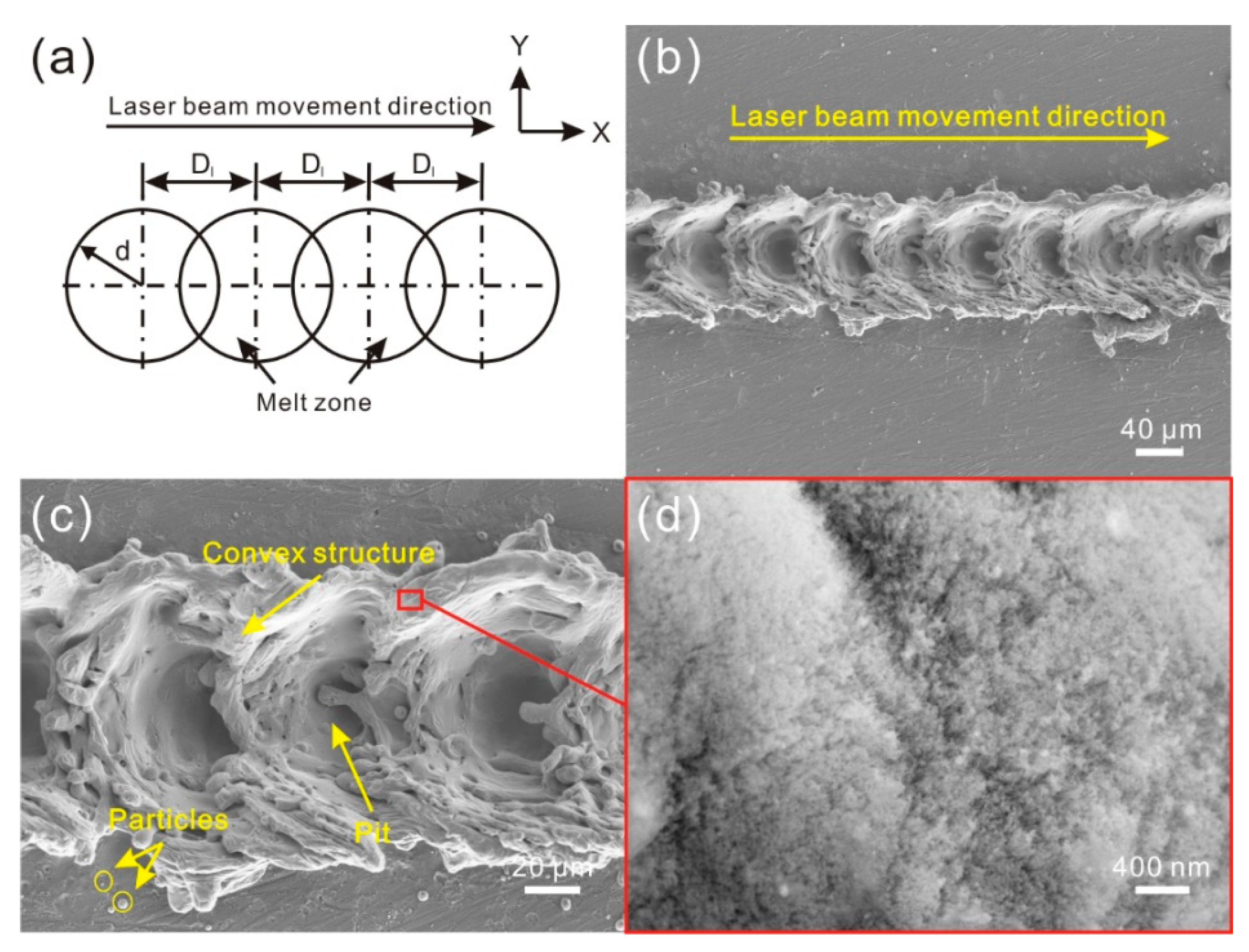
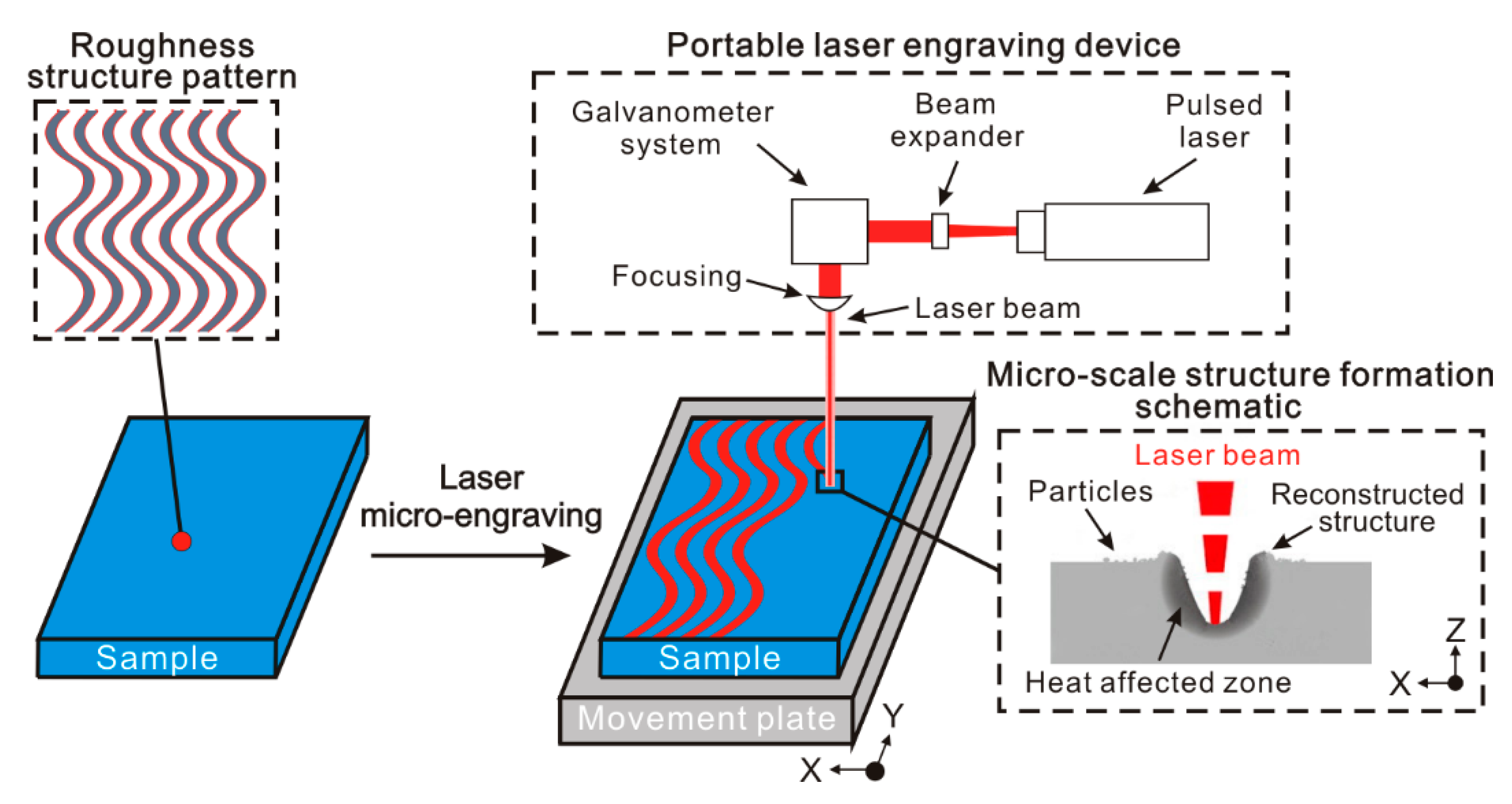
The treatment process and schematic of the micro-scale roughness structure construction approach are shown in
Figure 1. Before treatment, according to the macroscopic morphology of the prepared roughness structure, the roughness structure pattern was designed. Due to the open-end design of the pattern, a roughness structure with complicated morphology can easily be prepared on the surface by this method. During laser micro-engraving treatment, laser beam will travel along with the pattern at a constant speed. From the micro-scale structure formation schematic, it can be easily found that the material of surface layer is melted rapidly when the laser beam continuously irradiates the surface, leading to the formation of a molten pool. Then, some melted material in the molten pool is vaporized and removed, which results in the formation of a concave structure and heat-affected zone. Simultaneously, because of the laser beam impact force, a part of melted material is squeezed out from concave structure and piles up together, which forms the reconstructed structure (convex structure). Furthermore, due to the different pressure between vaporized material and atmospheric, blasting and splashing phenomenon occurs in the molten pool. The splashing melted material will form particles in the air. These particles are randomly distributed on the reconstructed structure and untreated surface. Since the diameter of the laser beam used for portable laser engraving device is about 80 μm, the as-prepared structure is micro-scale in structure. Furthermore, the portable laser engraving device which is generally used to engrave the label of items is cheap and common. The efficiency of treatment is very high as well, for the scanning speed can be as high as 1 m/s. Therefore, the micro-scale roughness structure construction approach is convenient, low-cost and high-efficient. More importantly, because of no requirement for the thickness and area of the treated material, it is suitable for engineering application.
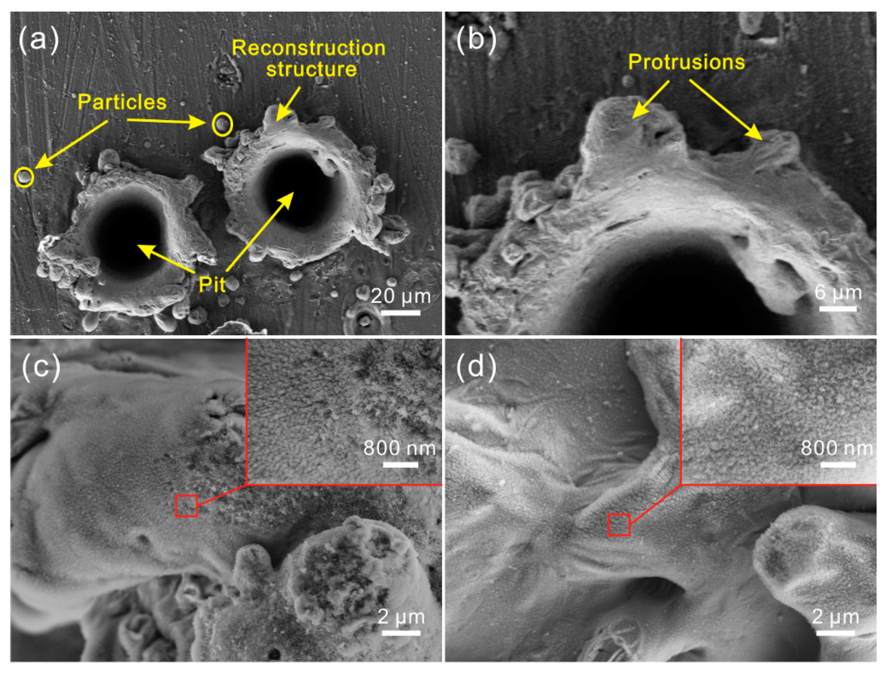
The SEM image of the Al alloy surface after laser micro-engraving (laser beam pulse frequency of 10,000 Hz, laser beam scanning speed of 0 m/s) is shown in
Figure 2a. Clearly, due to no movement of the laser beam, a circular pit was constructed on the Al alloy. Around the pit, irregular reconstruction convex structures could be easily observed. Moreover, some spherical particles were randomly distributed on the convex structure surface. From the high-magnification SEM image shown in
Figure 2b, it was seen that some irregular protrusions were formed on the convex structure surface. Additionally, fold could be observed easily on the circular pit, which indicated that the formation of the pit was not mainly due to the material vaporization, but rather, the melted material squeeze induced by laser beam impact force. As shown in
Figure 2c,d, it was obvious that the surfaces of the convex structure and pit were covered with a myriad of regular flocculent nanostructures, indicating that laser micro-engraving treatment not only constructs microstructure on Al alloy surface, but also forms nanostructure.
3.2. Morphology Evolution
According to the treatment process, the laser beam travels along a track which is set up at a constant speed during the treatment. Because of the pulse laser used for laser micro-engraving, as the laser beam moves, successive hemispherical molten pools with a constant distance form on the surface by each laser beam irradiation, which finally results in the formation of strip microstructure. As the distance of each molten pool changes, the morphology of the microstructure may greatly be affected. In the following, the strip microstructures with different molten pool spacing prepared by laser micro-engraving were investigated.
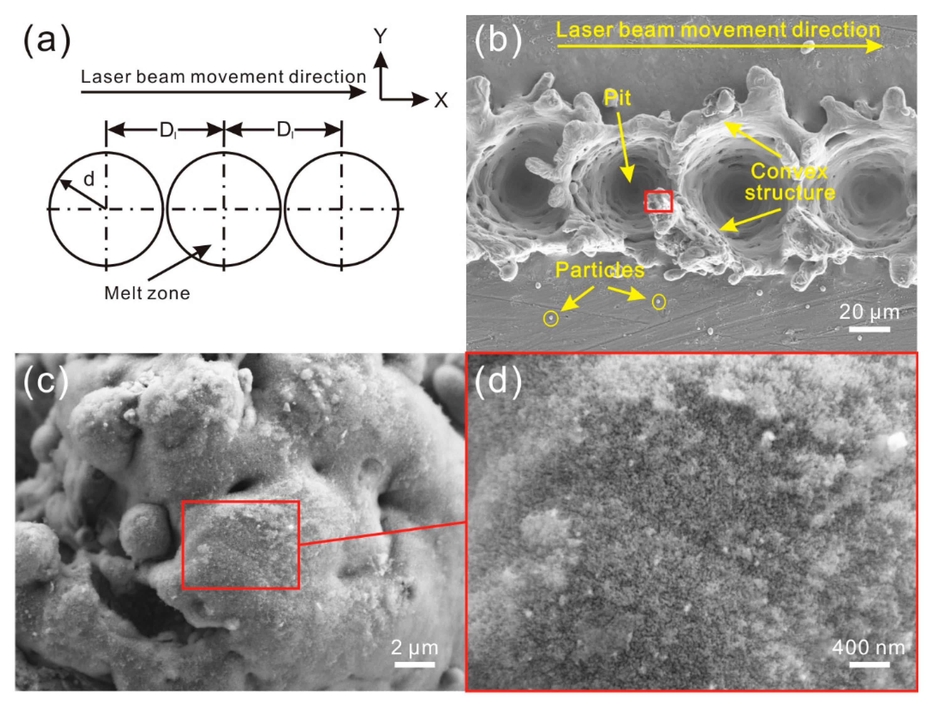
When each molten pool did not overlap with others (D
1 ≥ 2d) (
Figure 3a), as shown in
Figure 3b, successive and circular pits were constructed along the direction of laser beam movement on Al alloy surface. Each pit was individual and maintained the same diameter. Similar to the microstructure shown in
Figure 2a, the pits were surrounded by the irregular convex structure. Moreover, some particles with different sizes could be observed. From the high-magnification SEM images shown in
Figure 3c,d, flocculent nanostructure was formed on the microstructure surface.
With the decrease of distance of the molten pools, the molten pools come into contact with each other. When each molten pool overlaps with others one time (d ≤ D
1 < 2d) (
Figure 4a), the morphology of the treated surface is as shown in
Figure 4b. Though successive circular pits were prepared on the Al alloy surface, each pit contacted with the neighboring pit. As shown in
Figure 4c, the pits were still surrounded by convex structure. However, along the direction of laser beam movement, the convex structure where was in the overlap zone was much lower than the structure on both side of the pits. It indicates that the overlap of molten pool leads the melted material of previous reconstructed structure in the overlap zone to be squeezed to the two flanks of the pits by the laser beam impact force induced by follow-up laser beam. From the high-magnification SEM image shown in
Figure 4d, a similar phenomenon could be observed. Flocculent nanostructure was covered densely on the microstructure surface.
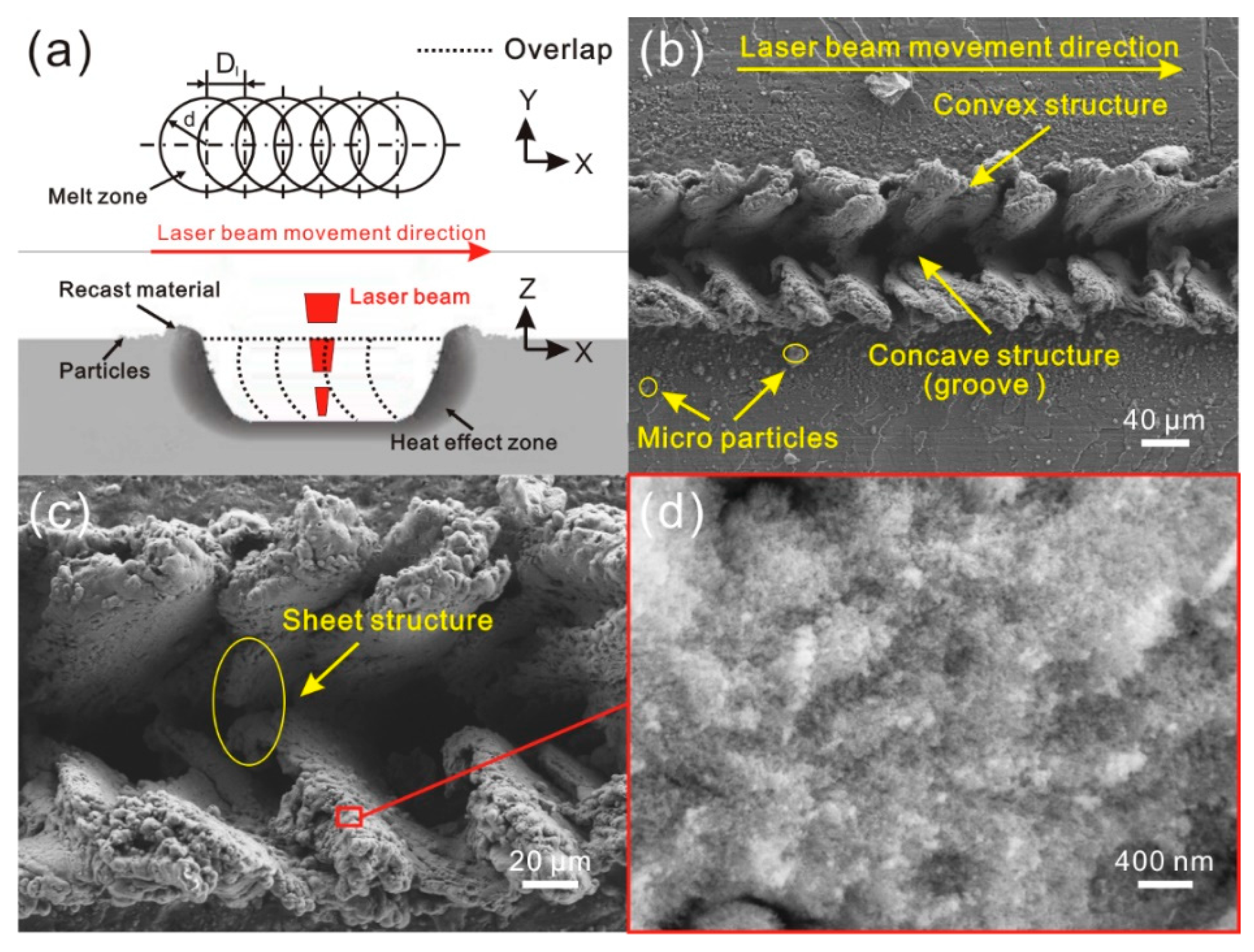
As the distance of molten pools further reduced, the overlap degree of molten pools increased. As shown in
Figure 5a, when each molten pool overlapped with others for more than one time (0 < D
1 < d), the microstructure on Al alloy surface showed great change (
Figure 5b). Strip groove was formed instead of successive circular pits on the surface. Moreover, the reconstructed sheet convex structures were arranged parallel to each other along the direction of laser beam movement. The angle between the sheet convex structure and strip groove was about 30°. Additionally, the number of the particles covered on the convex structures increased dramatically. As shown in
Figure 5c, the sheet microstructure constructed by the remainder of the melted material that was not squeezed out appeared at the bottom of the strip groove, further indicating that the formation of the depression structure is mainly due to the melted material squeeze induced by laser beam impact force. As the distance of molten pool reduces, the times of laser beam impact (per unit area) increase. The effect of the laser beam impact on melted material is similar to plowing, leading to the aforementioned change of as-prepared microstructure. Meanwhile, the degree of blasting and splashing of the melted material also improves. From the high-magnification SEM image shown in
Figure 5d, the strip groove surface was covered with flocculent nanostructure, indicating that the nanostructure can be formed on the Al alloy surface under different laser parameters (laser beam pulse frequency and laser beam scanning speed).
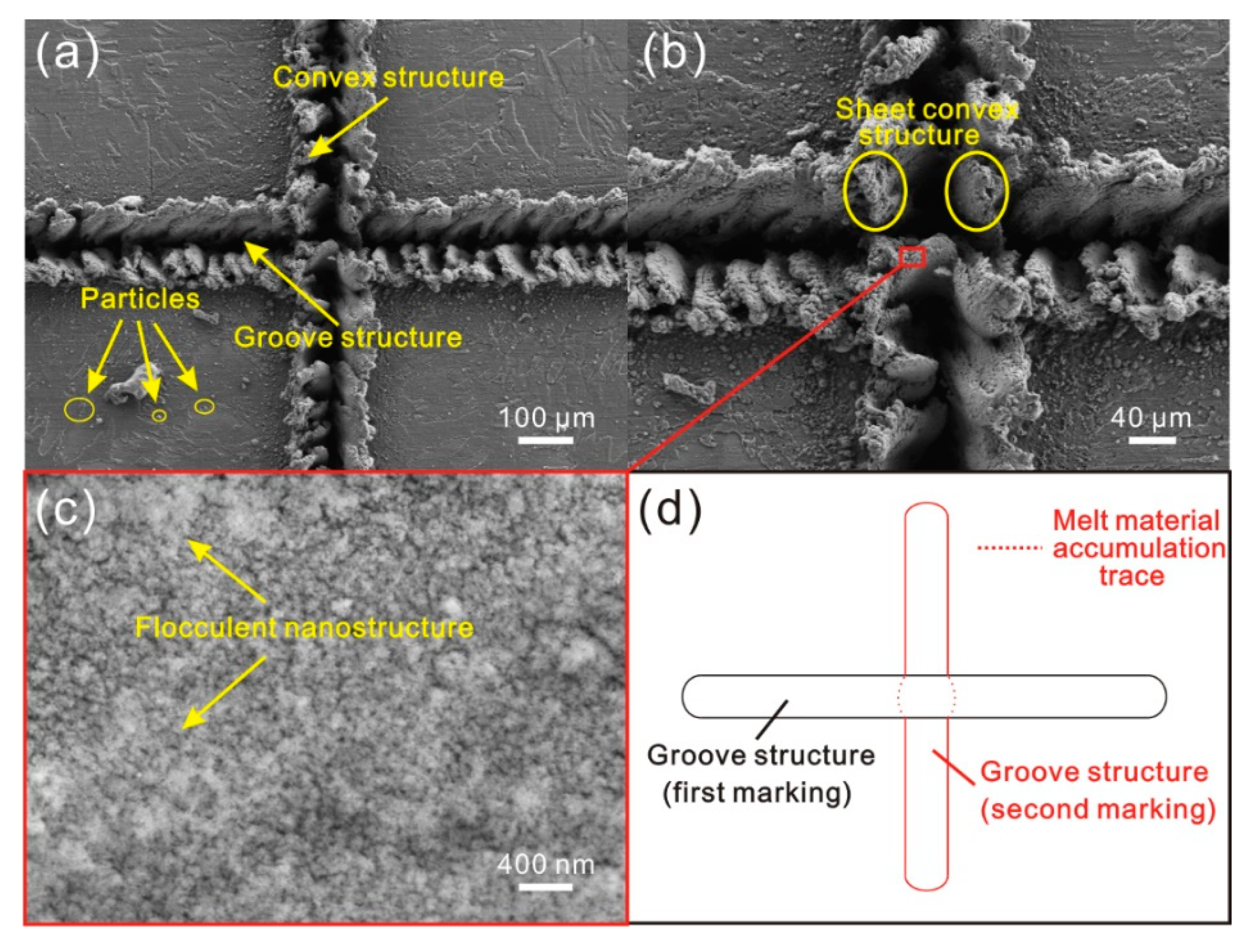
In the following, the cross microstructure composed of strip microstructures was also investigated. The morphology of the cross microstructure is shown in
Figure 6. Because of the same parameters, the strip grooves and convex structure were the same as the microstructures shown in
Figure 6b. However, at the intersection area of the two strip grooves, the irregular sheet microstructure that was perpendicular to the horizontal strip groove was constructed. Moreover, compared with the other area, the untreated surface near the intersection area was covered with a much larger number of particles. As shown in
Figure 6c, there were numerous flocculent nanostructures on the sheet microstructure surface. From the schematic of the preparation of cross microstructure shown in
Figure 6d, it could be found that the melted material accumulated at the intersection area was affected by laser beam impact force again during the second laser micro-engraving treatment (constructing vertical strip groove). The melted material was squeezed into the horizontal strip groove, resulting in the formation of sheet convex microstructure. At the same time, due to the effect of the laser beam on the material at of the intersection area, the degree of blasting and splashing of the melted material increased.
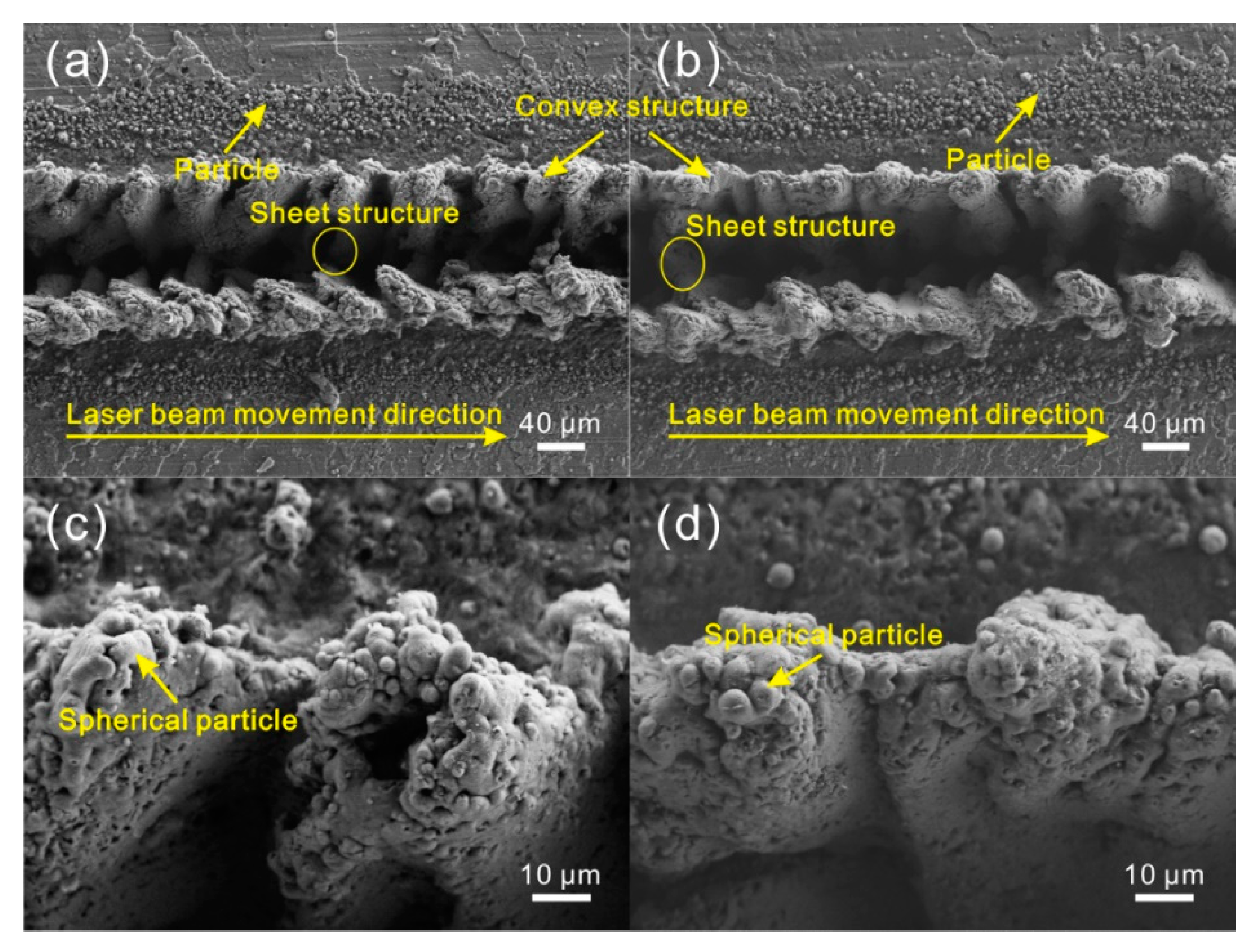
The following part investigated the influence of laser micro-engraving times on the morphology of treated strip microstructure. When the laser micro-engraving times increased to 2 (
Figure 7a,c), compared with the microstructure shown in
Figure 5b,c (laser micro-engraving of 1 time), the morphology almost had no obvious change. The width of the strip grooves still remained about 60 μm. However, the size of the sheet microstructure at the bottom of groove decreased with the increase of laser micro-engraving times. It was difficult to observe the sheet structure. Furthermore, the convex structures became smaller and more individual than before. The number of the particles covered on the convex structure increased significantly. As the laser micro-engraving times further increased, the strip grooves remained unchanged (
Figure 7b,d). But the sheet microstructure at the bottom of groove disappeared. Additionally, humps were formed on the both sides of the strip groove. Due to the increase of laser micro-engraving times, the number of particles covered on the microstructure surface further increased.
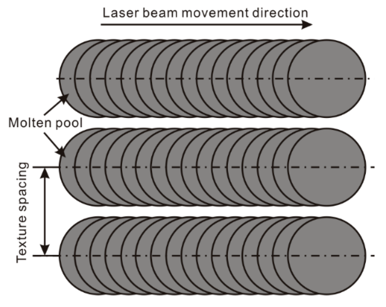
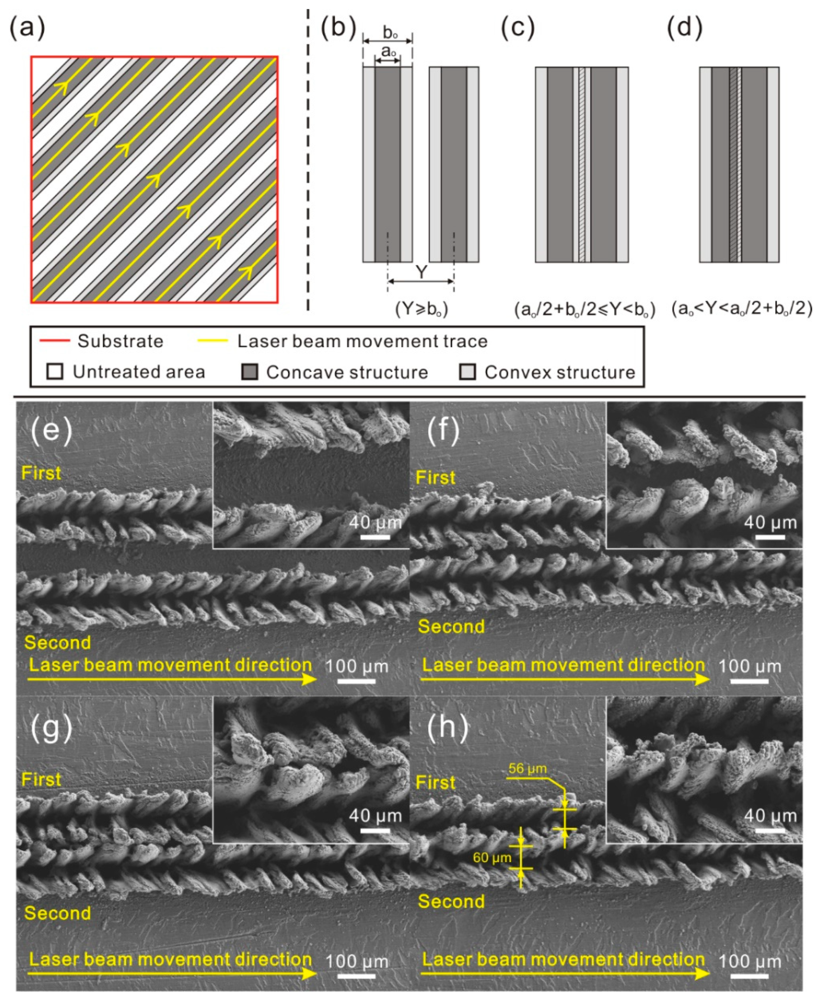
According to the treatment process, the laser beam travels along a designated track. From
Figure 8a, it is found that the microstructure on the surface is composed of numerous parallel strips. The spacing of strip microstructure (texture spacing) may greatly affect the morphology of the as-prepared microstructure. In order to reveal the effect of texture spacing on the roughness structure, the morphology of the strip microstructures with different texture spacing was observed and analyzed. As shown in
Figure 8b–d, some conclusions could be drawn on the strip microstructures with different texture spacing: (1) Strip microstructures do not contact with each other (
Figure 8b); (2) Convex structures of strip microstructures contact with each other (
Figure 8c); (3) Convex structures contact with the concave structure of other strip microstructures (
Figure 8d). As shown in
Figure 8e,f, since there was no contact between the microstructures, the strip microstructure on the surface had no change with the decrease of texture spacing. Reduction was only observed in the width of the untreated surface between two strip microstructures. When the convex structures of strip microstructures were contacting with each other (
Figure 8g), the strip grooves were not affected. However, the convex structures of strip microstructures were flocked together, resulting in the formation of peak-like microstructure. As the texture spacing further decreased (
Figure 8h), no obvious change was found in the two strip grooves, but the width of the first-fabricated strip grooves (56 μm) was a little shorter than that of the second one (60 μm). From the SEM image presented in the inset of
Figure 8h, interconnected sheet microstructures appeared, instead of the strip peak-like structure. This is because that some part of the convex structure of the first strip microstructure is melted again when second strip microstructure is prepared. Meanwhile, this melted material gathers with the melted material squeezed from the second strip groove in the overlap zone, resulting in the decrease in the width of the first strip groove.
3.3. Morphology Regulation Rule
According to
Figure 9, due to the effect of the laser beam pulse frequency on the number of laser beam irradiations per second and the energy of each laser beam pulse, the diameter and distance of the molten pool are related to the laser beam pulse frequency. Additionally, the laser beam scanning speed can affect the distance between each molten pool directly. Therefore, it can be speculated that the laser beam pulse frequency and scanning speed of laser micro-engraving treatment have a great influence on the morphology of the as-prepared microstructure. In order to get an insight into the effect of laser parameters on the microstructure, systematic investigation was performed on the morphology of the strip microstructures treated by different laser beam scanning speed and pulse frequency.
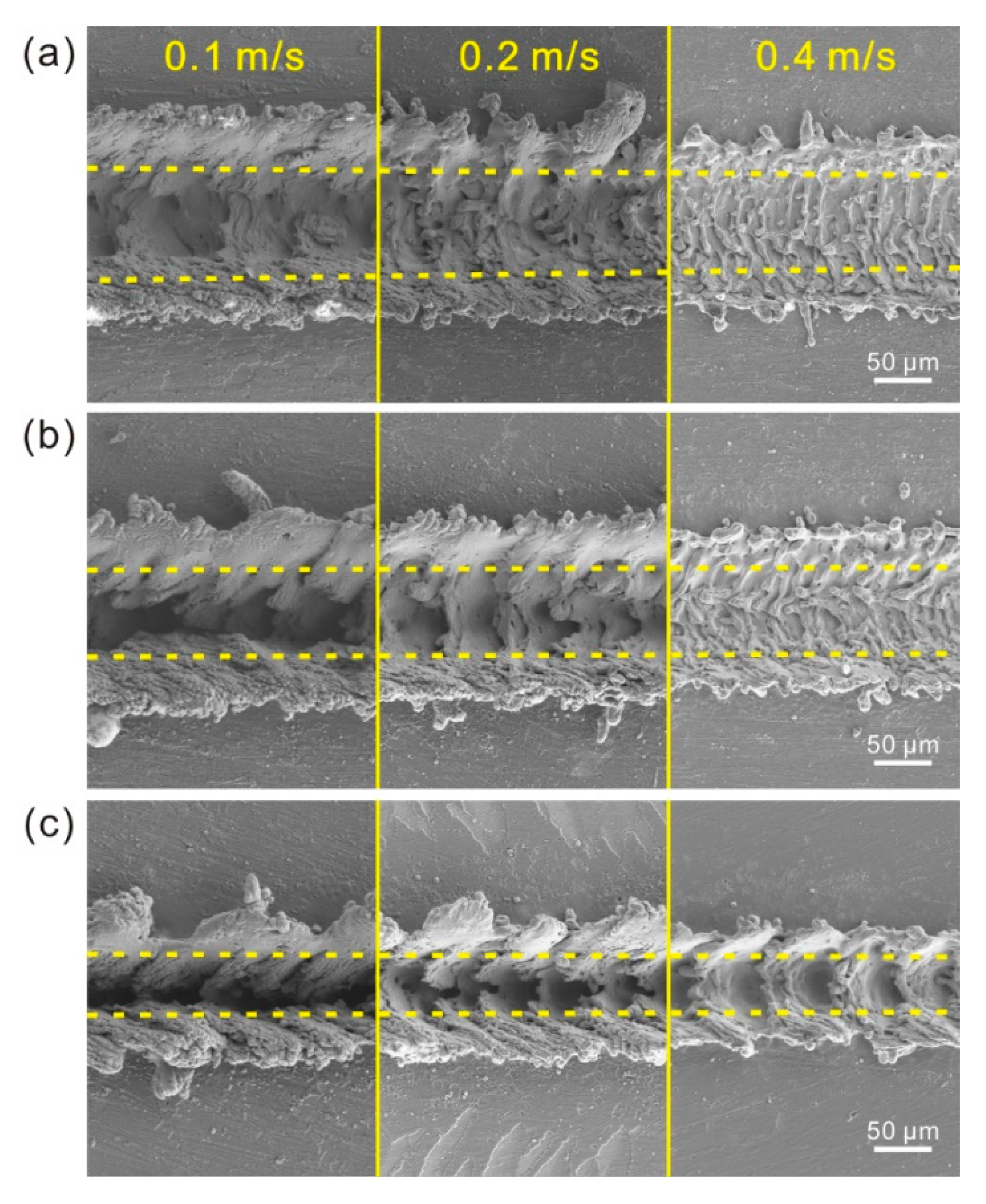
As shown in
Figure 10a, under the laser beam pulse frequency of 3000 Hz, as the laser beam scanning speed increased, the concave structure maintained its strip groove. However, the depth of the groove significantly decreased. Simultaneously, the size of the convex structure on the both sides of the strip groove reduced. The convex structure became more individual and irregular, leading to the transformation of convex microstructure into individual hump. The amount of fold microstructure at the bottom of the groove increased with the increase of scanning speed as well. Furthermore, the number of the particles on the untreated surface became fewer. When the laser beam pulse frequency was 5000 Hz and 8000 Hz, similar phenomenon was observed (
Figure 10b,c). The results indicate that laser beam scanning speed has a great influence on the morphology and size of as-prepared microstructure (convex and concave structures). Because of the unchanged energy of laser beam, the diameter of hemispherical molten pool almost maintains a constant value as laser beam scanning speed increases. But the overlap degree of molten pool decreases. Thus, the melt degree of the material in the depth direction (−Z-axis) reduces dramatically. Moreover, the effect of laser beam impact on melted material per unit area and the degree of blasting of melted material become weak as scanning speed increases. As shown in
Figure 10c, due to the decrease of overlap degree of molten pool, the concave structure transformed from strip groove to successive pits as the scanning speed increased to 0.4 m/s, which was consistent with the aforementioned results.
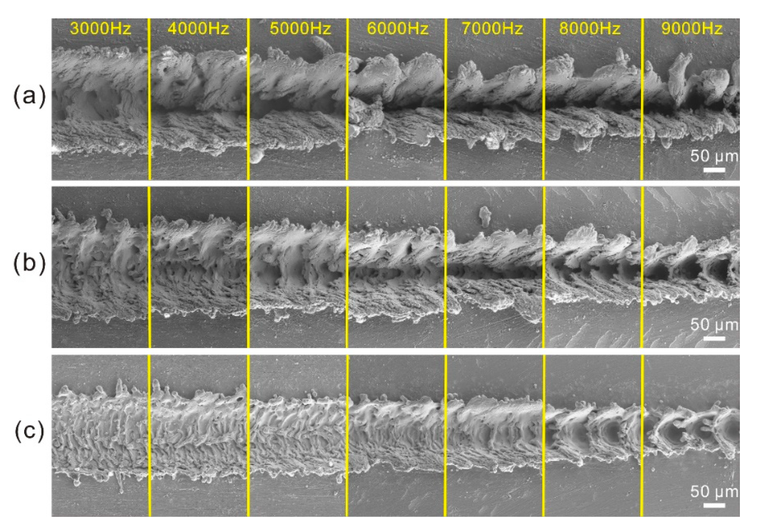
The morphologies of the microstructures treated with different laser beam pulse frequencies are shown in
Figure 11. When the laser beam scanning speed was 0.1 m/s, strip groove was observed on Al alloy surface (
Figure 11a). Nevertheless, the width of the strip groove and the convex structure on both sides of the strip groove decreased greatly with the increase of laser beam pulse frequency. In contrast, the depth of the strip groove increased. Meanwhile, the number of fold microstructures at the bottom of the strip groove and the irregular protrusions on the microstructure reduced dramatically with the increase of laser beam pulse frequency, meaning that the convex and concave microstructures of the surface become more and more regular. When the laser beam scanning speeds were 0.20 m/s and 0.4 m/s respectively, the morphology of the microstructure exhibited similar change as the laser beam pulse frequency increased. The above results indicate that the laser beam pulse frequency can affect the microstructures of the surface greatly. According to the mechanism of laser micro-engraving treatment, the energy of each laser beam reduces with the increase of laser beam pulse frequency. Thus, the diameter of molten pool has a decrease, leading to the decrease of width of the strip groove. Meanwhile, the distance between each molten pool decreased with the increase of laser beam pulse frequency. The decrease of the diameter of molten pool and the distance between each molten pool mutually resulted in the raise of melt degree of material in depth direction (−Z-axis). Furthermore, the reduction of distance between each molten pool enhanced the effect of laser beam impact on the melted material per unit area. Squeezing action was improved. Hence, the depth of the groove increased dramatically. The microstructure of the surface became more and more regular. Actually, if the decrease rate of the distance of each molten pool is much higher than that of the diameter of molten pool, the overlap degree of molten pool will increase with the increase of laser beam pulse frequency. In contrast, the overlap degree of molten pool will decrease by increasing laser beam pulse frequency. Thus, the overlap degree of the molten pool increased and then decreased with the increase of laser beam pulse frequency from 3000 to 9000 Hz. As shown in
Figure 11c, when the laser beam pulse frequency increased to 8000 Hz, due to the one-time overlap of each molten pool with others, the concave structure became successive pits.
To further understand the effect of laser parameters on the as-prepared microstructure and to achieve the controllable preparation of microstructure on Al alloy surface, the following part explored the variations of the geometrical dimensions of strip microstructure with laser beam pulse frequency and scanning speed. The dimension of the microstructures of the treated surface shown in
Figure 11 was measured on a Contour Elite I 3D optical surface profiler. Measurements were conducted five times and the mean value was adopted.
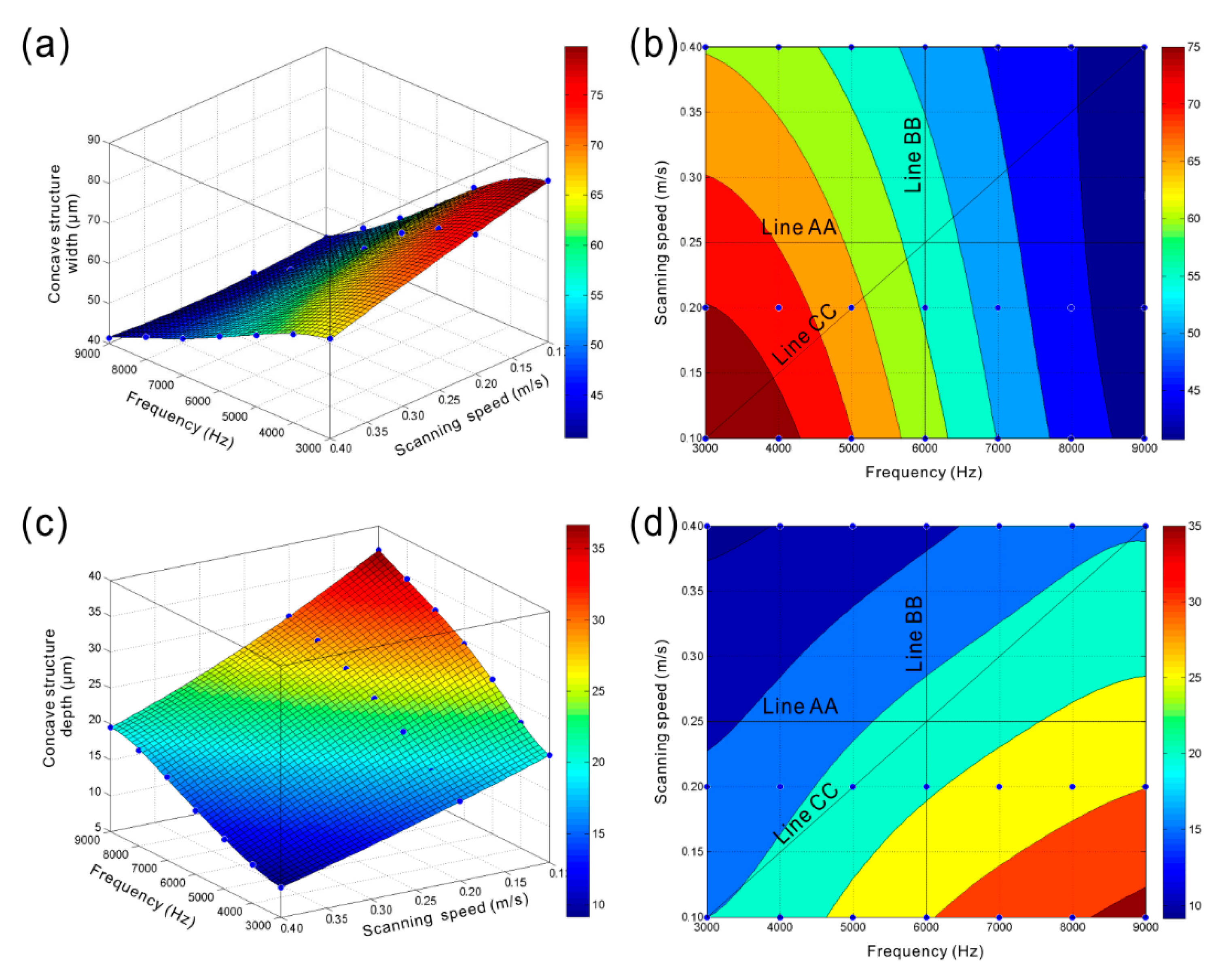
Figure 12a,b present the variations of width of concave structure (pit or groove) of the strip microstructure with laser beam pulse frequency and scanning speed. Obviously, as the laser beam pulse frequency increased, the width of concave microstructure reduced significantly (line AA shown in
Figure 12b). However, the width of concave structure had a slight decrease with the increase of laser beam scanning speed (line BB shown in
Figure 12b). The aforementioned results indicate that the overlap degree of molten pool has little effect on the width of concave microstructure. The width is mainly affected by the diameter of molten pool. The width of concave microstructure of the strip structure would dramatically decrease as the laser beam pulse frequency and scanning speed increased simultaneously (line CC shown in
Figure 12b). From
Figure 12c,d, opposite variation could be found. The depth of concave structure gradually increased with the increase of laser beam pulse frequency (line AA shown in
Figure 12d). In contrast, the depth of concave structure of the strip microstructure declined as the laser beam scanning speed rose (line BB shown in
Figure 12d). According to the above research, both the increase of overlap degree and the size of hemisphere molten pool can increase the depth of concave structure of the strip microstructure. Therefore, it can be concluded that the overlap degree of molten pool has more profound effect on the depth of the concave structure than the size of hemispherical molten pool. From the line CC shown in
Figure 12d, firstly, the depth of concave microstructure had a slight increase with the increase of laser beam pulse frequency and scanning speed. Then, due to the slight decrease of overlap degree of molten pool, the depth reduced as the laser beam pulse frequency increased to 8000 Hz.
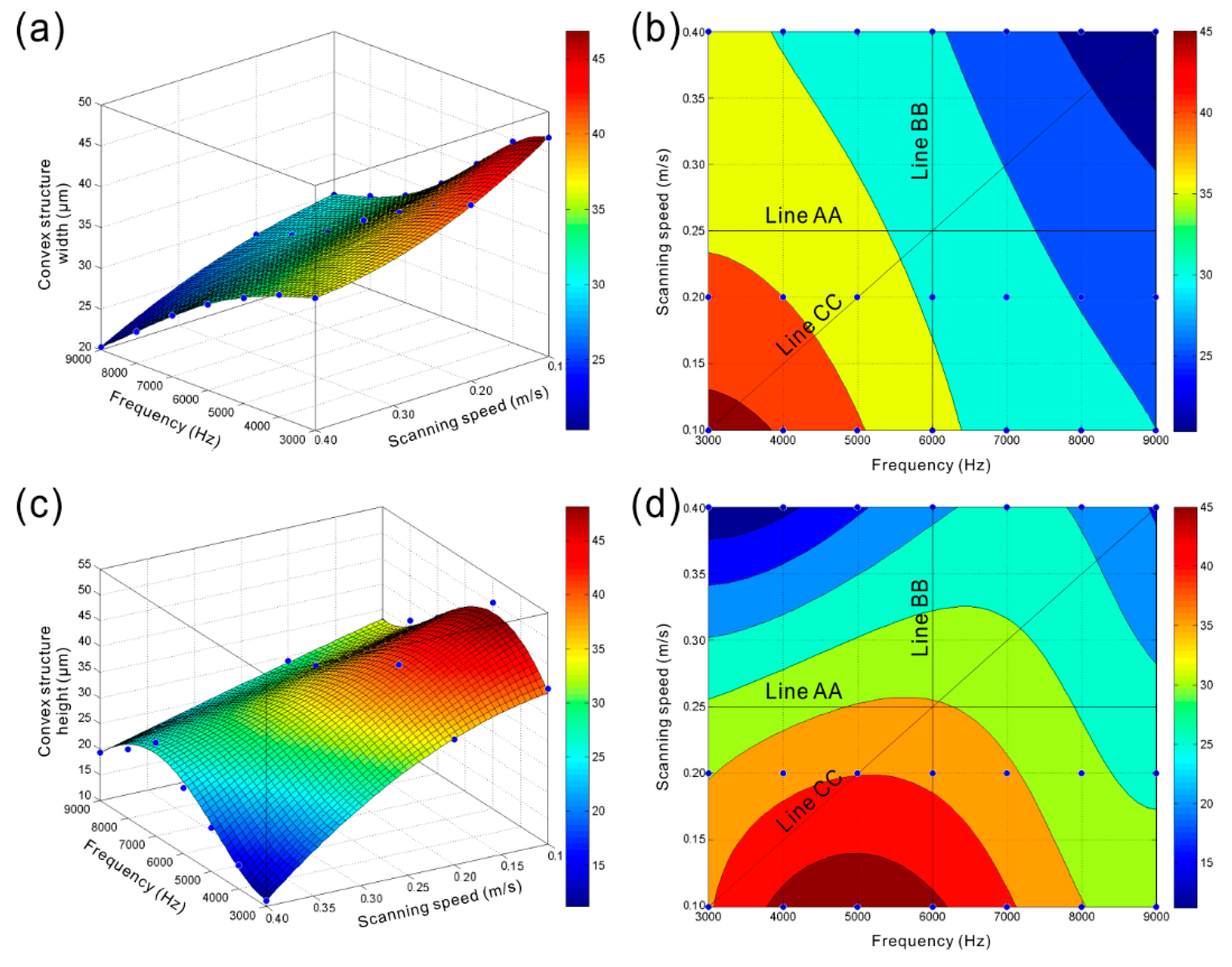
The variations of convex structure width of the strip microstructure with laser beam pulse frequency and scanning speed are shown in
Figure 13a,b. Obviously, the width of convex structure decreased with the increase of laser beam pulse frequency (line AA shown in
Figure 13b). It is considered that, due to the increase of melt degree of material in depth direction (−Z-axis) and the improvement of squeezing action, more melted material is squeezed out from the molten pool. As the depth of the concave structure increases gradually, the accumulation degree of melted material in the opposite direction of depth (+Z-axis) increases. Instead, the accumulation degree of melted material in the direction vertical to the laser beam movement direction has a decrease, leading to the decrease of convex structure width of the strip microstructure. As shown in
Figure 13b, the convex structure width decreased slowly with the increase of laser beam scanning speed, which resulted from the similar size of each molten pool. Actually, the decrease of overlap degree of the molten pool will lead to the reduction in the quantity of melted material per unit area. Meanwhile, the effect of the laser beam impact on the melted material per unit area becomes weak. From the line CC shown in
Figure 13b, as the laser beam pulse frequency and scanning speed increased at the same time, the width of convex structure would decrease sharply. The width decreased from 46.830 μm (laser beam pulse frequency of 3000 Hz, laser beam scanning speed of 0.1 m/s) to 20.320 μm (laser beam pulse frequency of 9000 Hz, laser beam scanning speed of 0.4 m/s).
Figure 13c,d show the variations of convex structure height of the strip microstructure with laser beam pulse frequency and scanning speed. Clearly, when the laser beam scanning was 0.25 m/s, the height of convex structure increased with the increase of laser beam pulse frequency from 3000 Hz to 6000 Hz. As laser beam pulse frequency further increased, the height of the convex structure decreased. A similar phenomenon could be observed under different scanning speeds. According to the above-obtained results, the increase of the height of convex structure resulted from the increase of melted material quantity per unit area and the accumulation degree of melted material in the opposite direction of depth (+Z-axis). When the laser beam pulse frequency further increases, though the melt degree of material in depth direction further increases, the size of hemispherical molten pool reduces dramatically, which further decreases the quantity of melted material per unit area. Moreover, due to the further increase of concave structure depth of the strip microstructure, the accumulation of melted material in the opposite direction of depth (+Z-axis) becomes more difficult. Thus, the height of the convex microstructure decreases. According to the line BB shown in
Figure 13d, because of the reduction of melted material per unit area and the weaker effect of the laser beam impact on the melted material, the height of convex structure showed a significant decrease with the increase of laser beam scanning speed. From the line CC shown in
Figure 13d, it could be speculated that the height of the convex structure increased and then gradually decreased with the increase of laser beam pulse frequency and scanning speed.
3.4. Roughness Structure Predictive Model
On the basis of the aforementioned results and by the method of data fitting, roughness structure predictive model was established, which clarified the relationship between the geometrical dimensions of the microstructure on Al alloy surface and laser parameters of laser micro-engraving treatment. The equations are shown as follows:
The width of concave structure of the constructed microstructure-D
1:
The depth of concave structure of the constructed microstructure-L
1:
The width of convex structure of the constructed microstructure-D
2:
The height of convex structure of the constructed microstructure-H
2:
where
x and
y represent laser beam pulse frequency (Hz) and laser beam scanning speed (m/s), respectively.
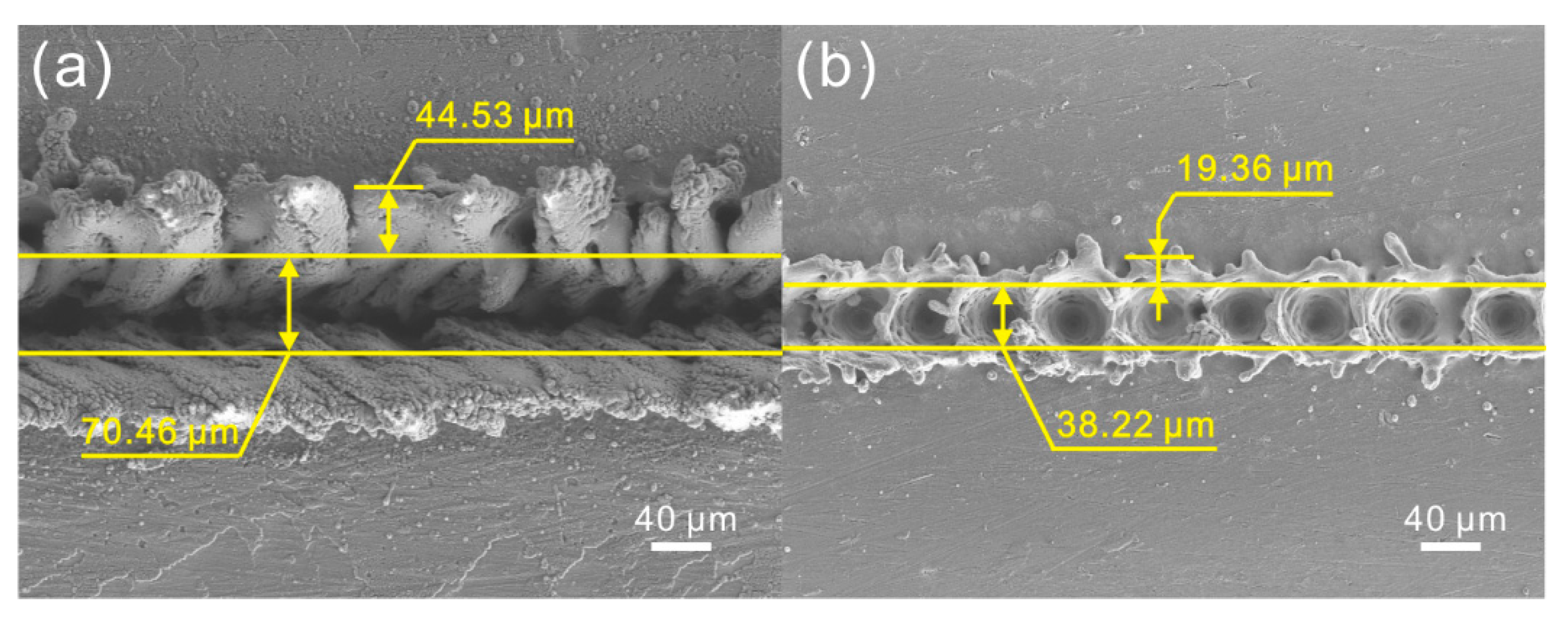
According to the mathematical relationship, the width and depth of concave structure of the microstructure on Al alloy surface treated under laser beam pulse frequency of 5000 Hz and scanning speed of 0.05 m/s were calculated to be 70.06 μm and 28.80 μm, respectively (
Table 1). And the width and height of the convex structure were 42.23 μm and 51.80 μm. As shown in
Figure 14a, the widths of concave and convex microstructures prepared under aforementioned laser parameters were 70.46 μm and 44.53 μm, respectively. Meanwhile, the depth of the concave structure (30.04 μm) and the height of convex structure (50.10 μm) measured by the optical surface profilers are exhibited in
Table 1. It could be found that the calculated dimensions of the microstructure were highly consistent with the results of actual measurement. For the microstructure treated under a laser beam pulse frequency of 10,000 Hz and a scanning speed of 0.4 m/s, similar phenomenon could be observed (
Table 1 and
Figure 14b). The results indicate that the prepared microstructures can be mathematically calculated by the established model instead of actual measurement. Moreover, the geometrical dimensions of the microstructure on Al alloy surface treated by laser micro-engraving can be predicted and regulated by the model in the future, which promotes achieving the controllable preparation of microstructure on Al alloy.
3.5. Chemical Composition
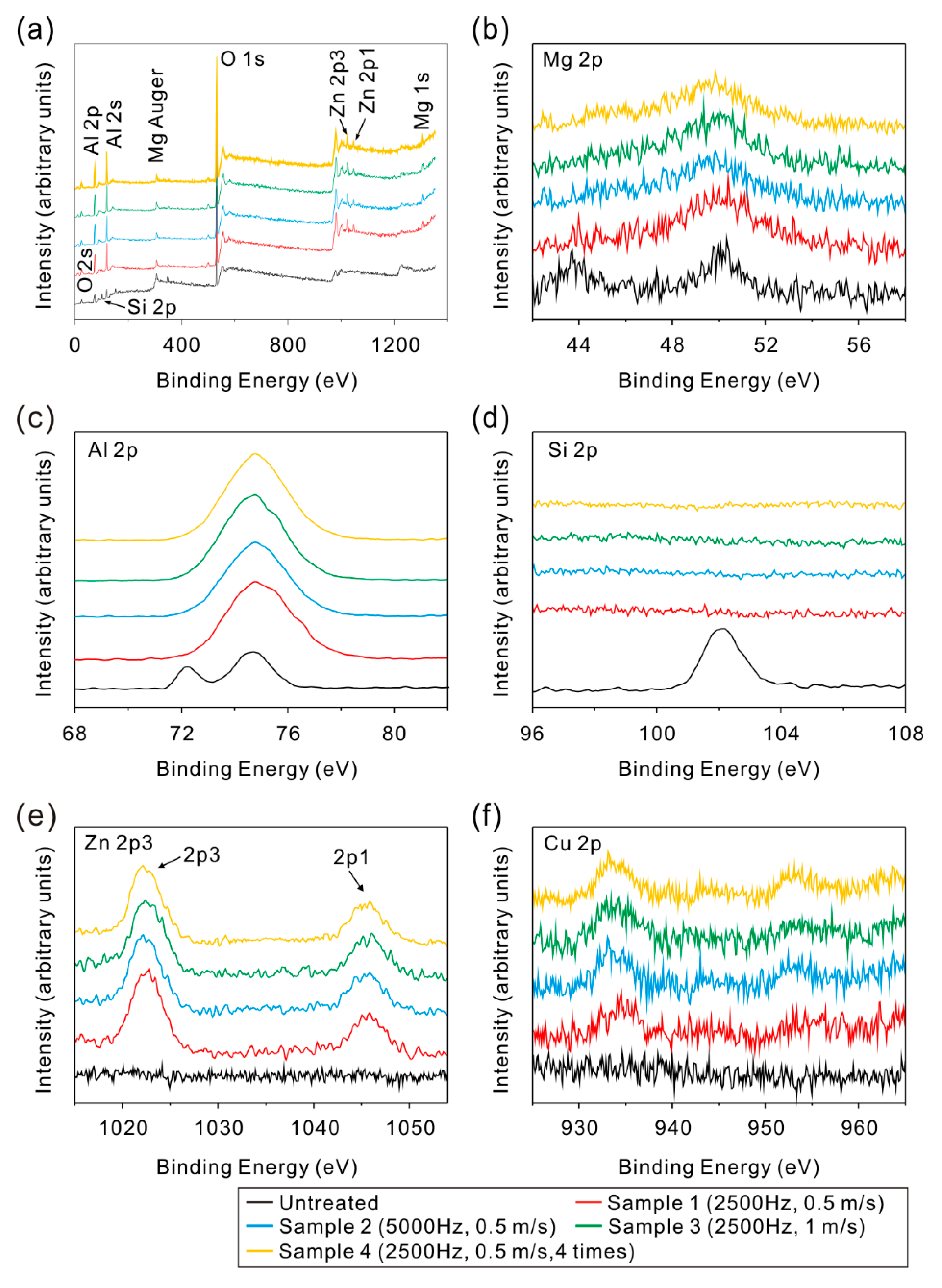
In addition to the change of microstructure morphology, the composition may change. In order to understand the change trend of composition, X-ray photoelectron spectroscopy (XPS) was carried out to investigate the composition of the as-prepared microstructure surfaces. From the XPS spectra shown in
Figure 15, compared with untreated surface, zinc and copper was detected on the treated microstructure surfaces. Meanwhile, silicon disappeared. As shown in
Figure 15c, both the peaks at 72.4 eV (Al
2O
3) and 74.7 eV (pure aluminum) were detected on the untreated surface. However, the peak at 72.4 eV disappeared after laser micro-engraving treatment, which indicated that the pure aluminum was completely oxidized to Al
2O
3 on the surface. From the element contents of the microstructure surfaces shown in
Table 2, the aluminum content decreased dramatically after laser treatment. In contrast, the content of oxygen significantly increased. The results in this research have a good agreement with previous studies [
32]. However, the chemical composition of microstructure surfaces treated with different process parameters almost remained the same, indicating that the process parameters (frequency, scanning speed and scanning times) have little effect on the composition of the as-prepared microstructure. The difference of the element content results from the change of surface morphology. Nevertheless, since the detection depth of XPS is less than 20 nm, the effect of surface morphology difference on the content of the elements measured by XPS is slight, which shows that the change is not readily obvious.


