Analysis of the Shear Behavior of Stubby Y-Type Perfobond Rib Shear Connectors for a Composite Frame Structure


Abstract
1. Introduction
2. Push-Out Tests of a Composite Structure Using Stubby Y-Type Perfobond Rib Shear Connectors
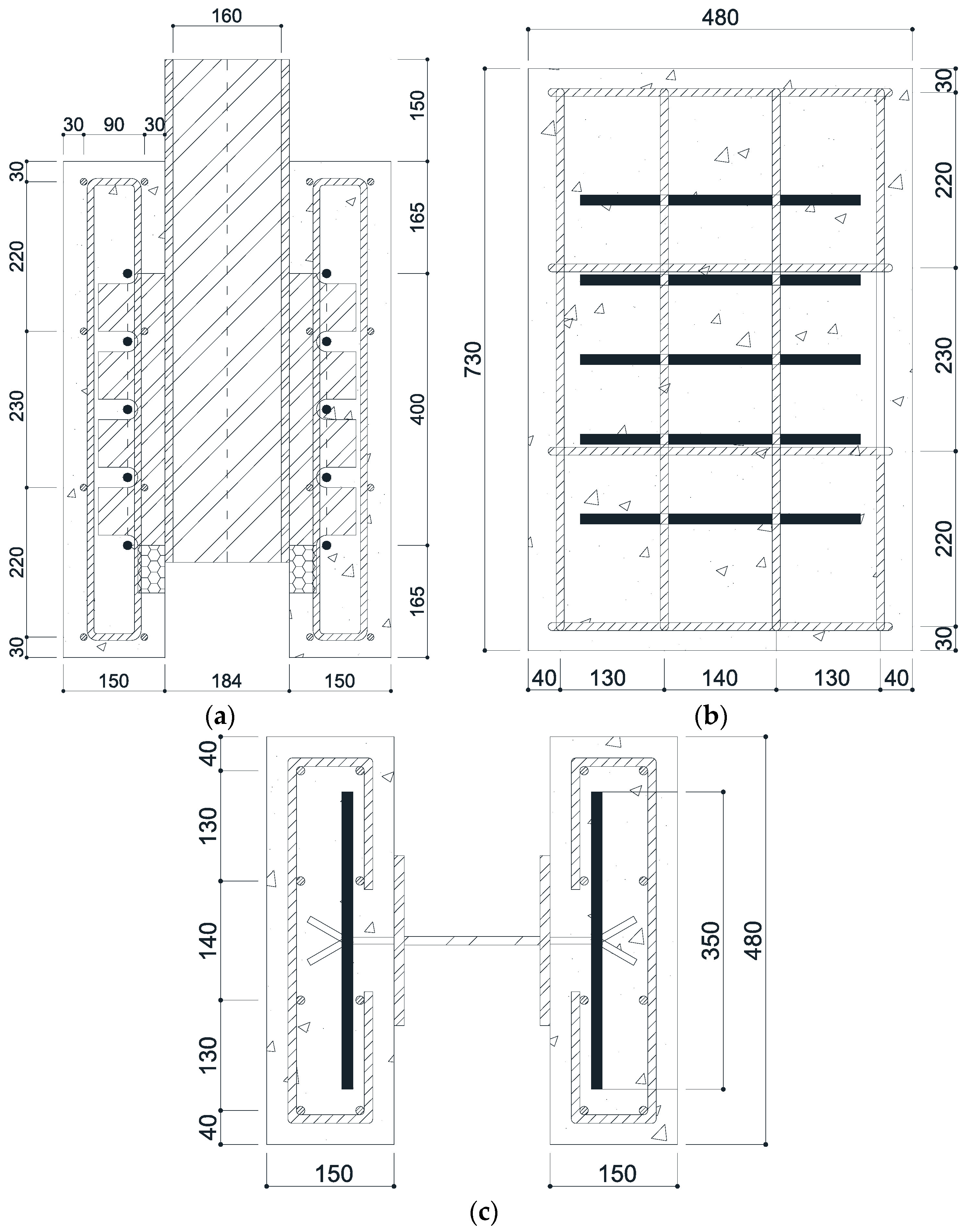
2.1. Test Specimens
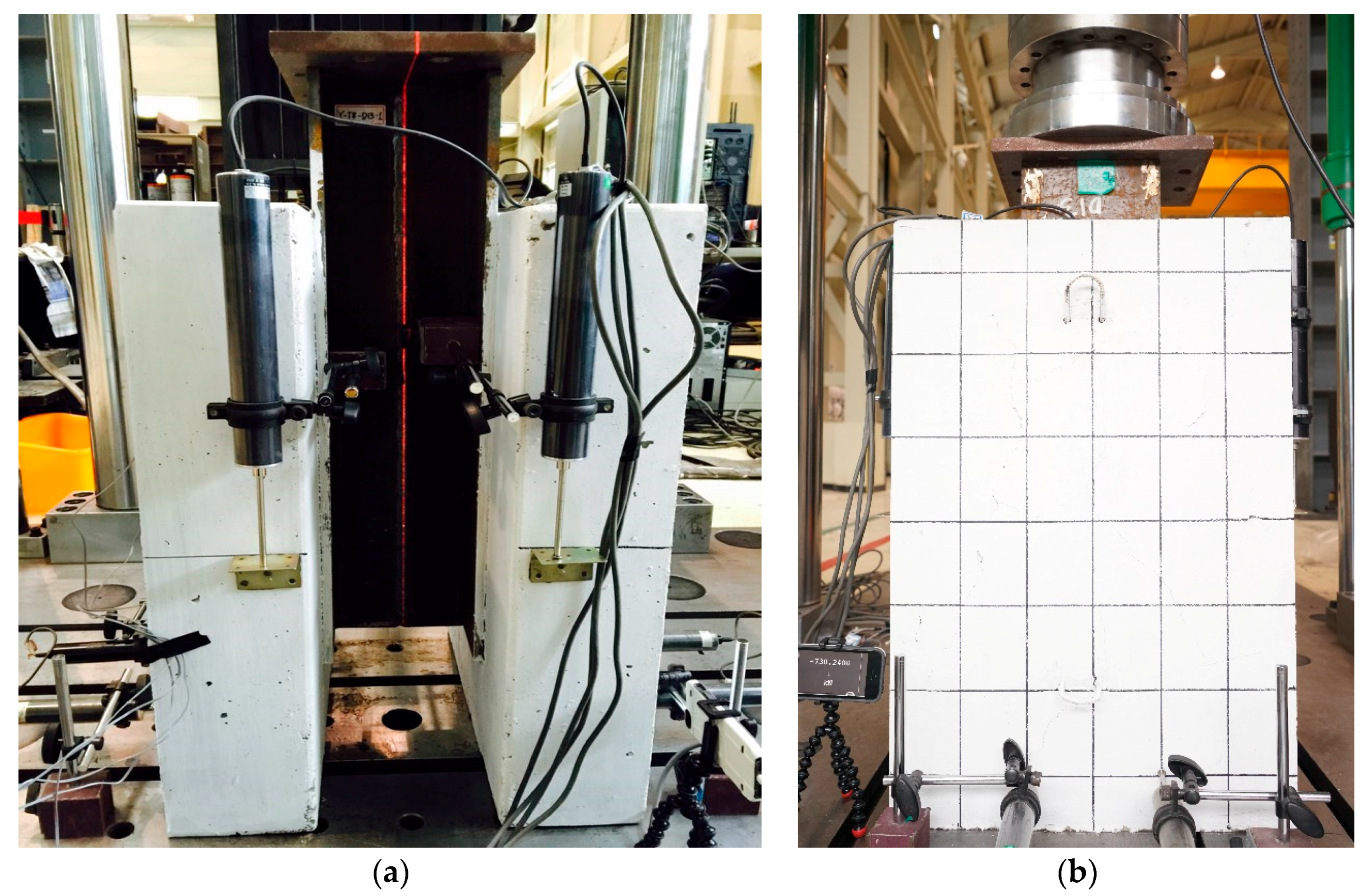
2.2. Test Procedure
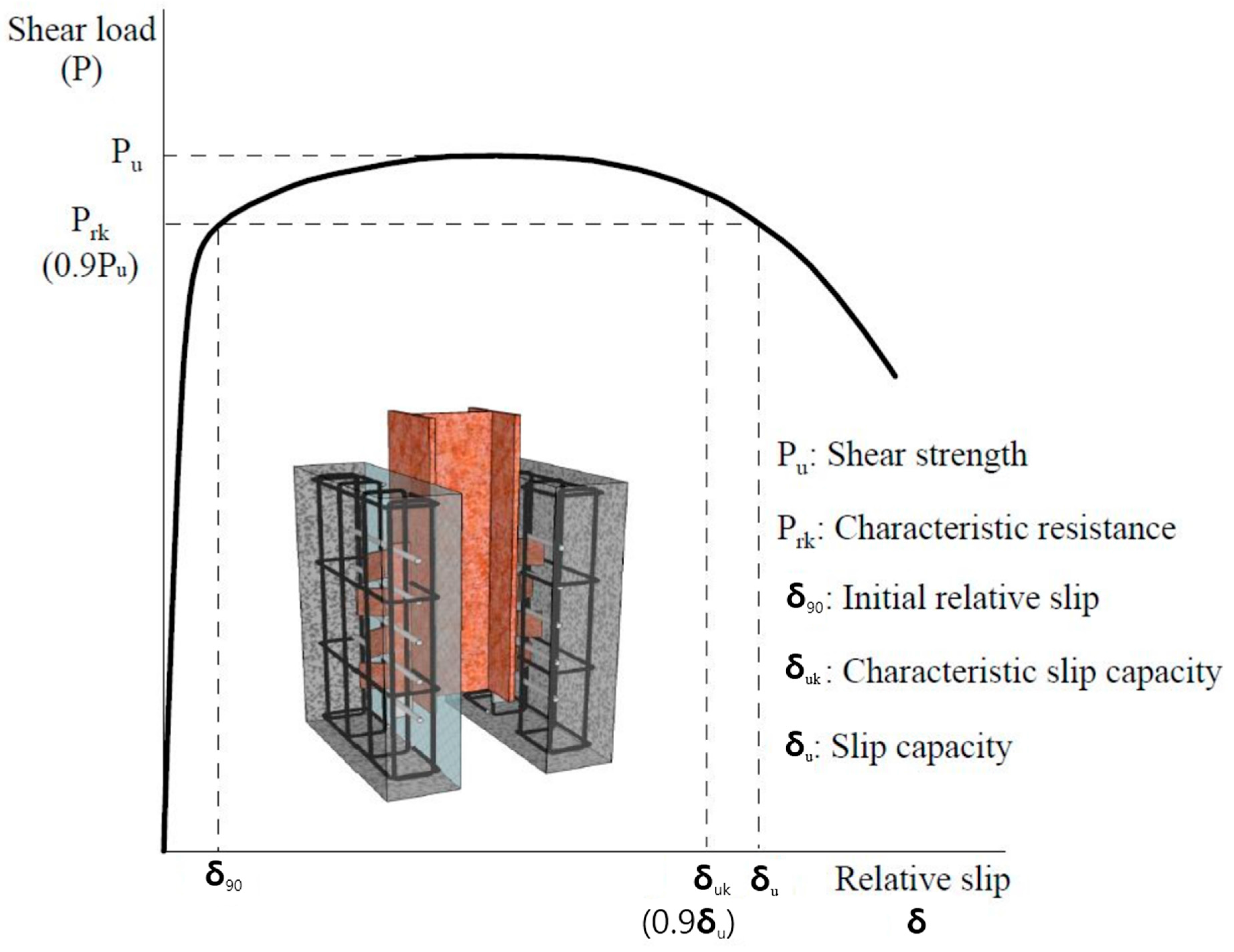
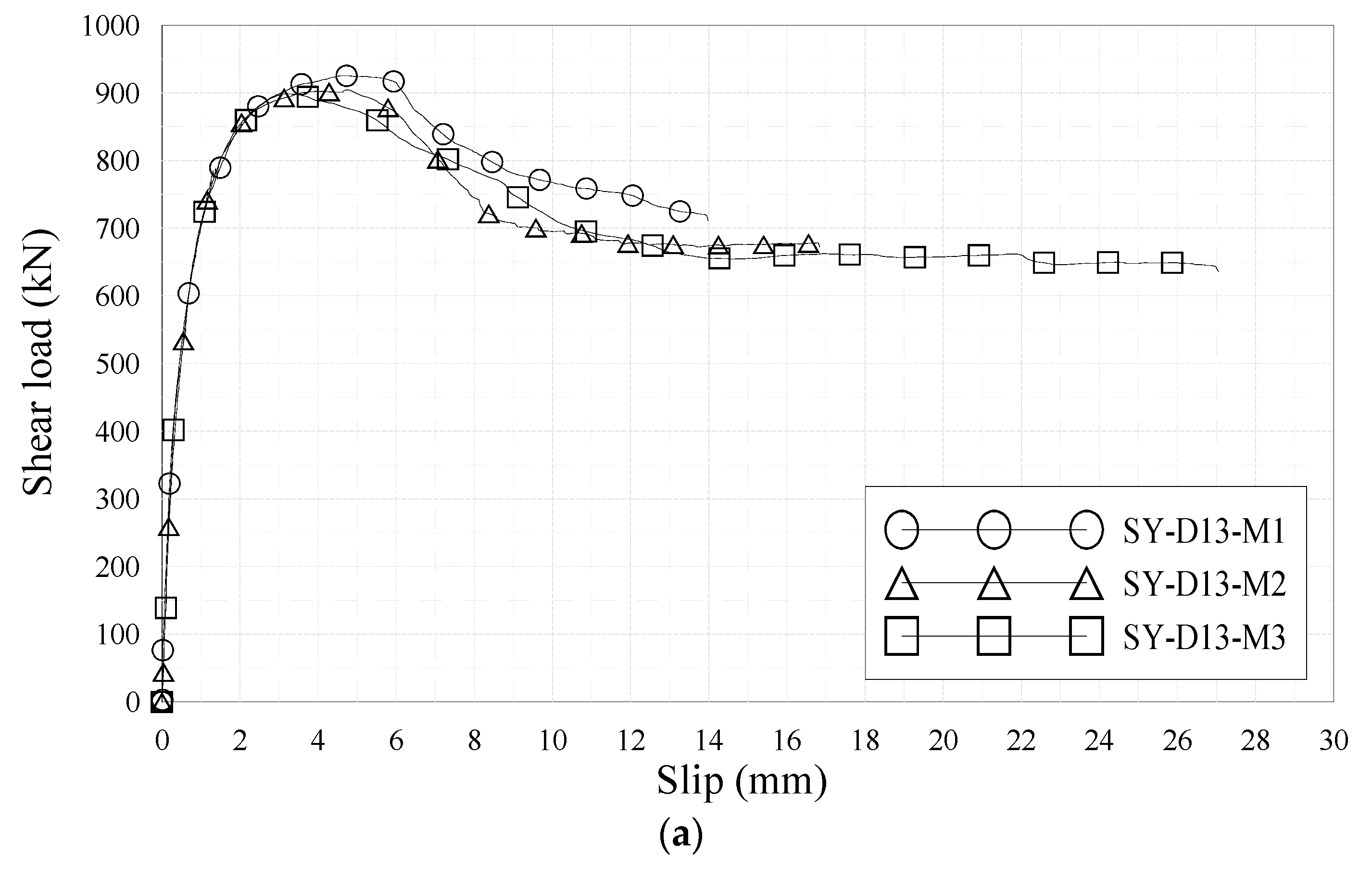
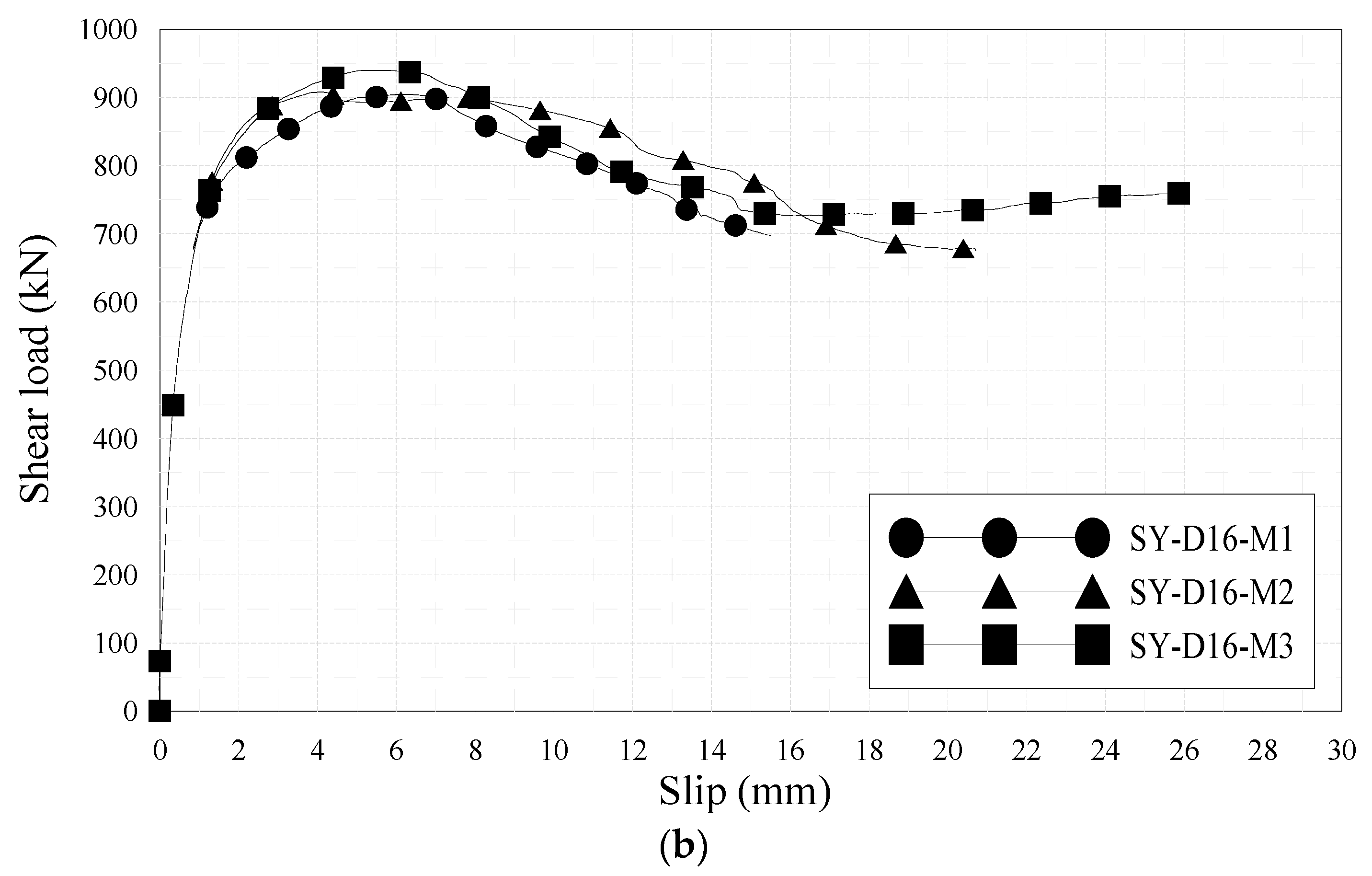
3. Shear Strength and Ductility of Composite Structures using Stubby Y-Type Perfobond Rib Shear Connectors
4. Failure of Composite Structures Using Stubby Y-Type Perfobond Rib Shear Connectors
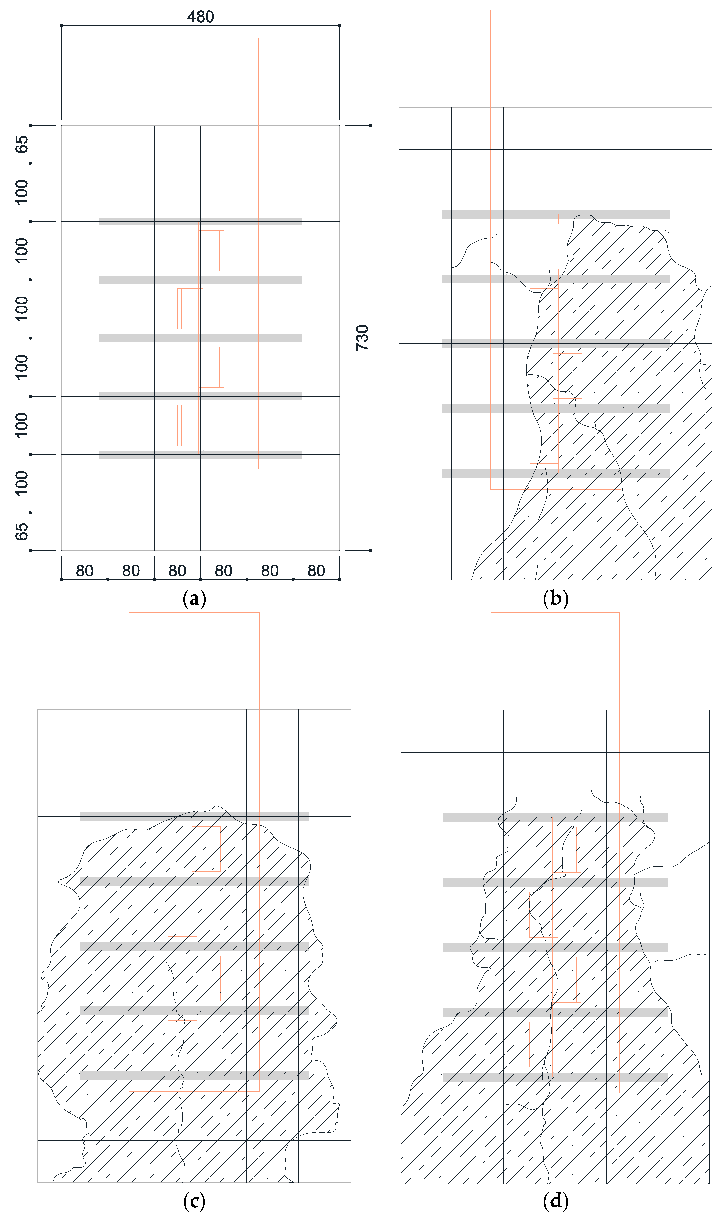
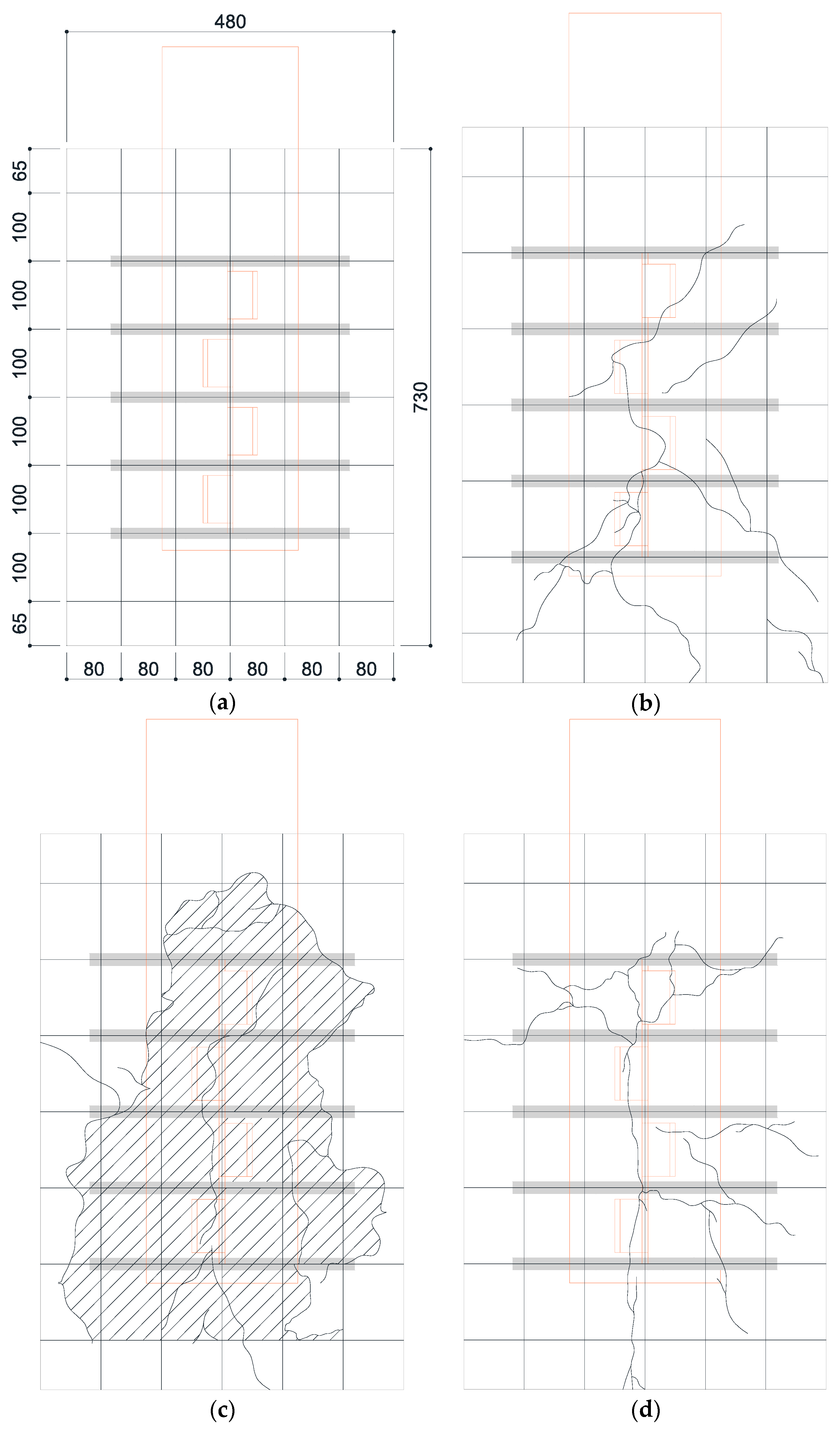
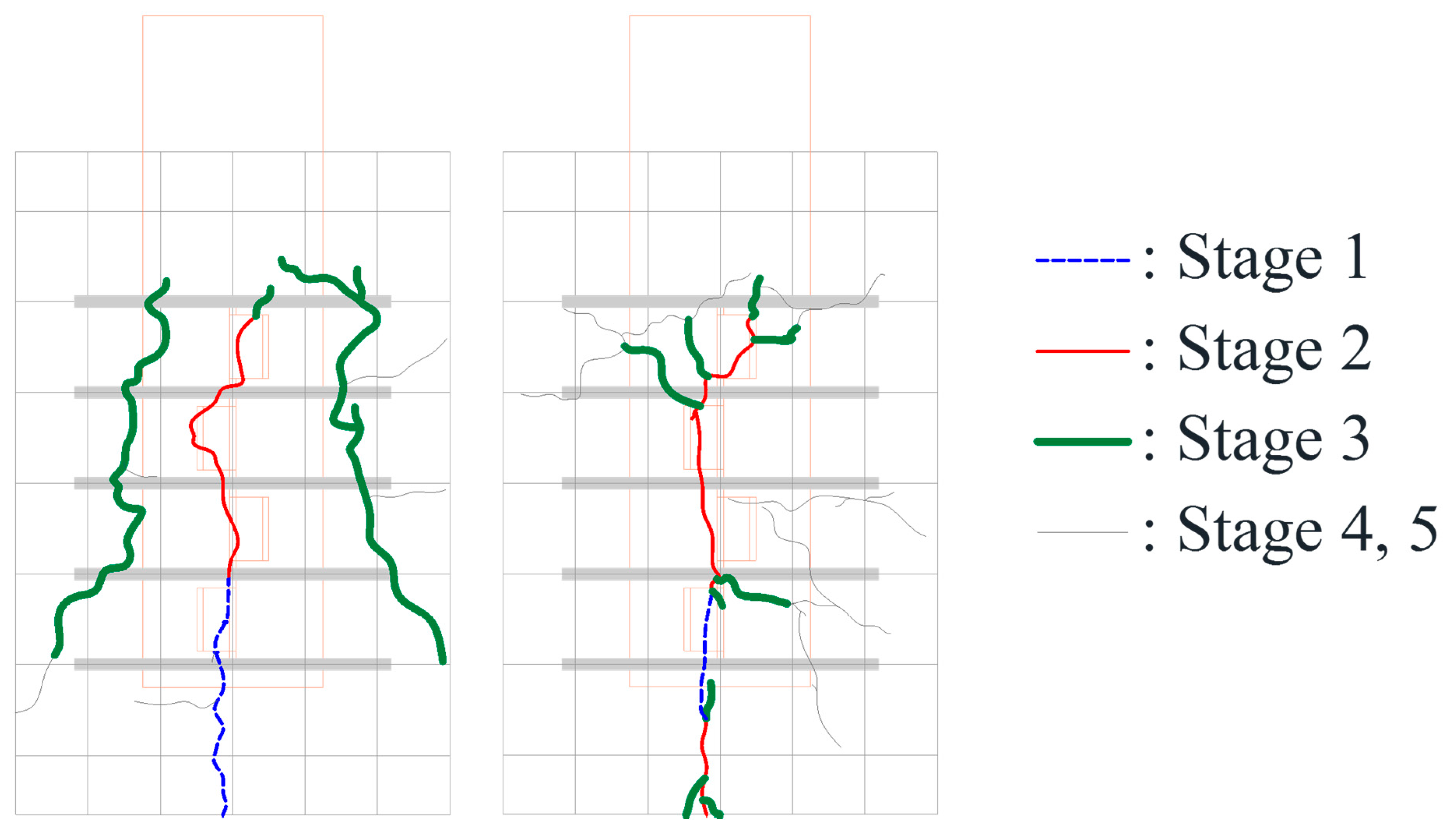
4.1. Concrete Crack Patterns and Failure of Stubby Y-Type Perfobond Rib Shear Connectors
- Stage 1: Occurrence of initial cracks (SY-D13-M3: 75% Pu; SY-D16-M3: 85% Pu)
- Stage 2: Shear strength (Pu)
- Stage 3: 80% shear strength
- Stage 4: Stiffness recovery (SY-D13-M3, δ = 17 mm; SY-D16-M3, δ = 18 mm)
- Stage 5: Ultimate limit state (δ = 25 mm)
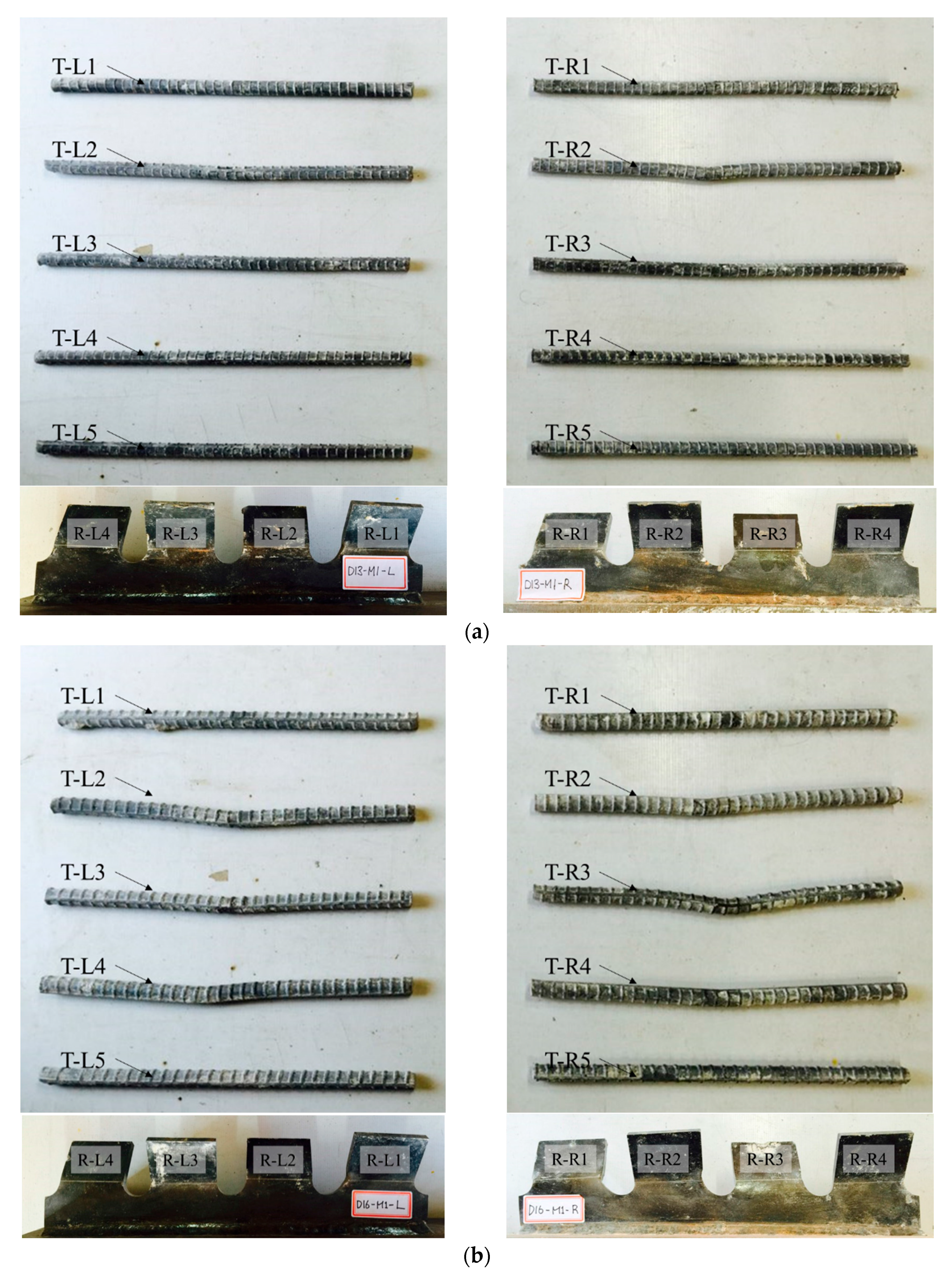
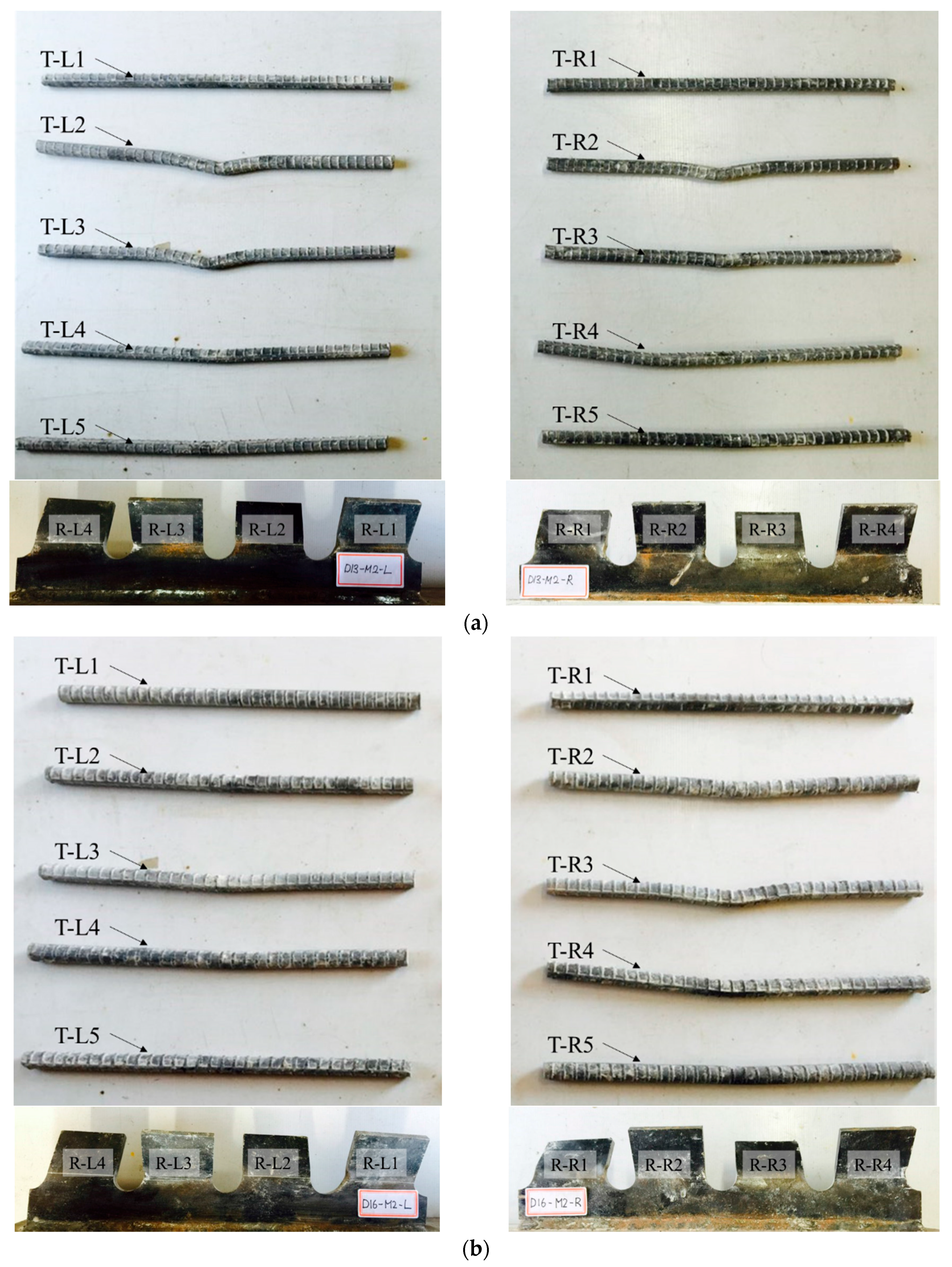
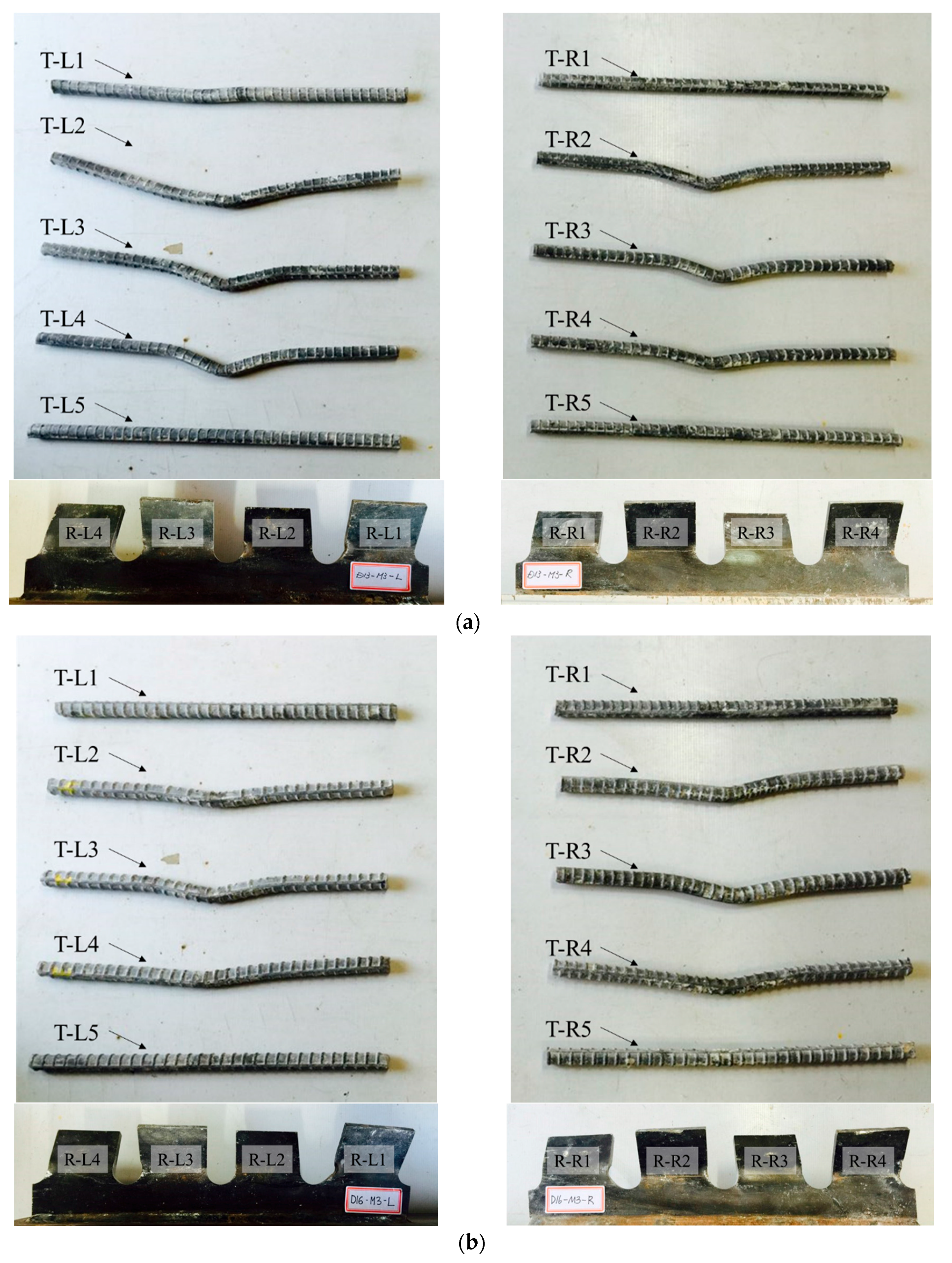
4.2. Deformation of Ribs and Transverse Rebars of Stubby Y-Type Perfobond Rib Shear Connectors
5. Conclusions
- (1)
- The push-out tests conducted using stubby-Y-type perfobond rib shear connectors with different transverse rebars (D13 and D16) indicated that the diameter of the transverse rebars did not considerably affect the change in shear strength. The shear strengths of the stubby Y-type shear connectors with D13 and D16 were 894.6 and 907.4 kN, respectively. That is, their shear strength per unit length (1 m) was approximately 2250 kN/m, which is a significant shear capacity for composite frames of building structures. The experimental results for shear strength showed a difference from the shear strength predicted using the existing equation for Y-type perfobond rib shear connectors (Equation (1); [32]); however, the equation slightly overestimated the influence of the rebar diameter. The increase of the shear strength with respect to the diameter of the transverse rebar was 12.8 (+1.43%) and 279.1 kN (+34.7%) according to the experimental results and the evaluation used in Equation (1), respectively. Based on this result, the term for the diameter of the transverse rebar in Equation (1) evaluates a higher strength than that in the experiment results. Therefore, to verify the applicability of the existing resistance formula, numerous parametric studies are required for stubby Y-type shear connectors.
- (2)
- In terms of ductility, both specimens (SY-D13-M and SY-D16-M) satisfied the ductility standard of Eurocode-4. The ductility of the stubby Y-type perfobond rib shear connector with transverse rebar D16 was 45.1% greater than that with D13. According to the assessment criteria for ductility provided by Kim et al. (2013), the ductility of the stubby Y-type perfobond rib shear connector with transverse rebar D16 was also 28.8% greater than that with D13. These results show that, when stubby Y-type perfobond rib shear connectors with identical rib sizes are used in composite frame structures, the structures with larger-diameter transverse rebars are preferable in terms of ductility.
- (3)
- Concrete crack distributions of the stubby Y-type perfobond rib shear connectors were detected based on the increase in relative slip. Most specimens started to show cracks at the bottom end of the cut rib. The initial cracks in SY-D13-M and SY-D16-M occurred at approximately 75% and 85% shear strength, respectively. In Stage 3, SY-D13-M developed additional vertical cracks, whereas SY-D16-M developed additional horizontal cracks. Then, all the crack patterns of the stubby Y-type perfobond rib shear connector with transverse rebar D13 appeared as pry-out failure of the concrete, while those of the shear connector with transverse rebar D16 displayed overall splitting failure of the concrete. Thus, it can be deduced that the load distribution on the transverse rebar, rib, and concrete is well balanced with increasing transverse rebar stiffness of the shear connector using transverse rebar D16, which has a relatively large cross-sectional area compared with the shear connector with transverse rebar D13. In addition, most rebars exhibited large deformations in Stage 5. These deformations delay concrete crushing in the dowel hole and prevent the brittle failure of shear connections after the ultimate limit state.
- (4)
- The difference of the shear force is low following the diameter of the transverse rebar. However, the size of the rebar affects the ductility and load distribution: a larger size shows better performance. Thus, it is expected that the size of the rebar affects the behavior of the whole shear connector system.
Acknowledgments
Author Contributions
Conflicts of Interest
References
- Naser, M.Z.; Kodur, V.K.R. Comparative fire behavior of composite girders under flexural and shear loading. J. Thin-Walled Struct. 2017, 116, 82–90. [Google Scholar] [CrossRef]
- Kodur, V.K.R.; Naser, M.Z.; Pakala, P.; Varma, A. Modeling the response of composite beam-slab assemblies exposed to fire. J. Constr. Steel Res. 2013, 80, 163–173. [Google Scholar] [CrossRef]
- Kim, S.H.; Kim, K.S.; Park, S.; Jung, C.Y.; Choi, C.J. Comparison of hysteretic performance of stubby Y-type perfobond rib. Eng. Struct. 2017, 147, 114–124. [Google Scholar] [CrossRef]
- Bursi, O.S.; Gramola, G. Behaviour of composite substructures with full and partial shear connection under quasi-static cyclic and pseudo-dynamic displacements. Mater. Struct. 2000, 33, 154–163. [Google Scholar] [CrossRef]
- Nakashima, M.; Matsumiya, T.; Suita, K.; Zhou, F. Full-scale test of composite frame under large cyclic loading. J. Struct. Eng. 2007, 133, 297–304. [Google Scholar] [CrossRef]
- Zhou, F.; Mosalam, K.M.; Nakashima, M. Finite-element analysis of a composite frame under large lateral cyclic loading. J. Struct. Eng. 2007, 133, 1018–1026. [Google Scholar] [CrossRef]
- Kim, H.Y.; Jeong, Y.J. Ultimate strength of a steel–concrete composite bridge deck slab with profiled sheeting. Eng. Struct. 2010, 32, 534–546. [Google Scholar] [CrossRef]
- Qureshi, J.; Lam, D.; Ye, J. Effect of shear connector spacing and layout on the shear connector capacity in composite beams. J. Constr. Steel Res. 2011, 67, 706–719. [Google Scholar] [CrossRef]
- Vasdravellis, G.; Uy, B. Shear strength and moment-shear interaction in steel-concrete composite beams. J. Struct. Eng. 2014, 140, 04014084. [Google Scholar] [CrossRef]
- Shariati, M.; Sulong, N.R.; Shariati, A.; Kueh, A.B.H. Comparative performance of channel and angle shear connectors in high strength concrete composites: An experimental study. Constr. Build. Mater. 2016, 120, 382–392. [Google Scholar] [CrossRef]
- Lasheen, M.; Shaat, A.; Khalil, A. Behaviour of lightweight concrete slabs acting compositely with steel I-sections. Constr. Build. Mater. 2016, 124, 967–981. [Google Scholar] [CrossRef]
- Caughey, R.A. Composite beams of concrete and structural steel. In Proceedings of the 41st Annual Meeting; Iowa Engineering Society: Des Moines, IA, USA, 1929; pp. 96–104. [Google Scholar]
- Viest, I.M. Investigation of stud shear connectors for composite concrete and steel T-beams. ACI J. Proc. 1956, 53, 875–891. [Google Scholar]
- Viest, I.M. Review of research on composite steel-concrete beams. J. Struct. Div. ASCE 1960, 86, 1–21. [Google Scholar]
- Slutter, R.G.; Fisher, J.W. Fatigue strength of shear connectors. Highw. Res. Rec. 1966, 147, 65–88. [Google Scholar]
- Ollgaard, J.G.; Slutter, R.G.; Fisher, J.W. Shear strength of stud connectors in lightweight and normal weight concrete. AISC Eng. J. 1971, 8, 55–64. [Google Scholar]
- Menzies, J.B. CP 117 and shear connectors in steel-concrete composite beams made with normal-density or lightweight concrete. Struct. Eng. 1971, 49, 137–154. [Google Scholar]
- Badie, S.S.; Tadros, M.K.; Kakish, H.F.; Splittgerber, D.L.; Baishya, M.C. Large shear studs for composite action in steel bridge girders. J. Bridge Eng. 2002, 7, 195–203. [Google Scholar] [CrossRef]
- An, L.; Cederwall, K. Push-out tests on studs in high strength and normal strength concrete. J. Constr. Steel Res. 1996, 36, 15–29. [Google Scholar] [CrossRef]
- Nguyen, H.T.; Kim, S.E. Finite element modeling of push-out tests for large stud shear connectors. J. Constr. Steel Res. 2009, 65, 1909–1920. [Google Scholar] [CrossRef]
- Leonhardt, F.; Andrä, W.; Andrä, H.P.; Harre, W. New advantageous shear connection for composite structures with high fatigue strength. Beton Stahlbetonbau 1987, 62, 325–331. [Google Scholar] [CrossRef]
- Oguejiofor, E.C.; Hosain, M.U. Behaviour of perfobond rib shear connectors in composite beams: Full-size tests. Can. J. Civ. Eng. 1992, 19, 224–235. [Google Scholar] [CrossRef]
- Oguejiofor, E.C.; Hosain, M.U. A parametric study of perfobond rib shear connectors. Can. J. Civ. Eng. 1994, 21, 614–625. [Google Scholar] [CrossRef]
- Oguejiofor, E.C.; Hosain, M.U. Numerical analysis of push-out specimens with perfobond rib connectors. Comput. Struct. 1997, 62, 617–624. [Google Scholar] [CrossRef]
- Valente, I.; Cruz, P.J. Experimental analysis of Perfobond shear connection between steel and lightweight concrete. J. Constr. Steel Res. 2004, 60, 465–479. [Google Scholar] [CrossRef]
- Vianna, J.D.C.; Costa-Neves, L.F.; Vellasco, P.D.S.; de Andrade, S.A.L. Structural behaviour of T-Perfobond shear connectors in composite girders: An experimental approach. Eng. Struct. 2008, 30, 2381–2391. [Google Scholar] [CrossRef]
- Vianna, J.D.C.; Costa-Neves, L.F.; Vellasco, P.D.S.; de Andrade, S.A.L. Experimental assessment of Perfobond and T-Perfobond shear connector’s structural response. J. Constr. Steel Res. 2009, 65, 408–421. [Google Scholar] [CrossRef]
- Vianna, J.D.C.; de Andrade, S.A.L.; Vellasco, P.D.S.; Costa-Neves, L.F. Experimental study of perfobond shear connectors in composite construction. J. Constr. Steel Res. 2013, 81, 62–75. [Google Scholar] [CrossRef]
- Lorenc, W.; Kożuch, M.; Rowiński, S. The behaviour of puzzle-shaped composite dowels—Part I: Experimental study. J. Constr. Steel Res. 2014, 101, 482–499. [Google Scholar] [CrossRef]
- Lorenc, W.; Kożuch, M.; Rowiński, S. The behaviour of puzzle-shaped composite dowels—Part II: Theoretical investigations. J. Constr. Steel Res. 2014, 101, 500–518. [Google Scholar] [CrossRef]
- Papastergiou, D.; Lebet, J.P. Design and experimental verification of an innovative steel–concrete composite beam. J. Constr. Steel Res. 2014, 93, 9–19. [Google Scholar] [CrossRef]
- Kim, S.H.; Choi, K.T.; Park, S.J.; Park, S.M.; Jung, C.Y. Experimental shear resistance evaluation of Y-type perfobond rib shear connector. J. Constr. Steel Res. 2013, 82, 1–18. [Google Scholar] [CrossRef]
- Kim, S.H.; Kim, K.S.; Park, S.; Ahn, J.H.; Lee, M.K. Y-type perfobond rib shear connectors subjected to fatigue loading on highway bridges. J. Constr. Steel Res. 2016, 122, 445–454. [Google Scholar] [CrossRef]
- Kim, S.H.; Heo, W.H.; Woo, K.S.; Jung, C.Y.; Park, S.J. End-bearing resistance of Y-type perfobond rib according to rib width–height ratio. J. Constr. Steel Res. 2014, 103, 101–116. [Google Scholar] [CrossRef]
- Kim, S.H.; Park, S.J.; Heo, W.H.; Jung, C.Y. Shear resistance characteristic and ductility of Y-type perfobond rib shear connector. Steel Compos. Struct. 2015, 18, 497–517. [Google Scholar] [CrossRef]
- Kim, S.H.; Choi, J.; Park, S.J.; Ahn, J.H.; Jung, C.Y. Behavior of composite girder with Y-type perfobond rib shear connectors. J. Constr. Steel Res. 2014, 103, 275–289. [Google Scholar] [CrossRef]
- Eurocode 4–1994, Design of Composite Steel and Concrete Structures, Part 1. 1: General Rules and Rules for Buildings. EN1994–1-1; European Committee for Standardization: Brussels, Belgium, 2004.


| Curing Time | Compressive Strength | |
|---|---|---|
| 21 days | 25.97 MPa | 27.17 MPa |
| 26.33 MPa | ||
| 29.22 MPa | ||
| 28 days | 28.27 MPa | 28.96 MPa |
| 29.83 MPa | ||
| 28.78 MPa | ||
| Before push-out test | 30.08 MPa | 29.29 MPa |
| 28.94 MPa | ||
| 28.84 MPa | ||
| Specimen | Yield Strength | Tensile Strength | Elongation | Young’s Modulus |
|---|---|---|---|---|
| S-1 | 318.48 MPa | 422.43 MPa | 39% | 209 GPa |
| S-2 | 338.36 MPa | 430.84 MPa | 41% | 209 GPa |
| S-3 | 332.35 MPa | 430.75 MPa | 41% | 209 GPa |
| S-4 | 340.73 MPa | 440.48 MPa | 40% | 209 GPa |
| Average | 332.48 MPa | 431.12 MPa | 41% | 209 GPa |
| Test Specimen | Y-Shaped Angle | Rib Thickness | Rib Height | Rib Width | Hole Diameter | Transverse Rebar |
|---|---|---|---|---|---|---|
| SY-D13-M1/M2/M3 | 60° | 8 mm | 50 mm | 70 mm | 30 mm | D13 |
| SY-D16-M1/M2/M3 | D16 |
| Specimen | Terminated Loading Point |
|---|---|
| SY-D13-M1/SY-D16-M1 | At 80% of the shear strength |
| SY-D13-M2/SY-D16-M2 | At the recovered stiffness |
| SY-D13-M3/SY-D16-M3 | At the displacement of 25 mm |
| Specimen | Pu (kN) | δuk (mm) | δu (mm) | δ90 (mm) | δu/δ90 | |
|---|---|---|---|---|---|---|
| SY-D13 | M1 | 925.2 | 6.61 | 7.34 | 1.82 | 4.03 |
| M2 | 904.4 | 6.20 | 6.89 | 1.60 | 4.31 | |
| M3 | 898.7 | 5.85 | 6.50 | 1.66 | 3.92 | |
| Average | 894.6 | 6.90 | 7.67 | 1.59 | 4.82 | |
| Strength predicted using Equation (1) [32] | 803.5 | |||||
| SY-D16 | M1 | 904.1 | 9.55 | 10.61 | 2.24 | 4.74 |
| M2 | 907.7 | 11.20 | 12.44 | 1.63 | 7.63 | |
| M3 | 939.7 | 8.78 | 9.75 | 2.12 | 4.64 | |
| Average | 907.4 | 10.01 | 11.12 | 1.79 | 6.21 | |
| Strength predicted using Equation (1) [32] | 1082.6 | |||||
| Test Specimen | |||||||||||
|---|---|---|---|---|---|---|---|---|---|---|---|
| SY-D13-M1/M2/M3 | 30 | 50 | 8 | 27 | 4 | 126.7 | 400 | 3 | 2 | 130 | 803.5 |
| SY-D16-M1/M2/M3 | 30 | 50 | 8 | 27 | 4 | 198.6 | 400 | 3 | 2 | 130 | 1082.6 |
| Stage | SY-D13-M3 | SY-D16-M3 |
|---|---|---|
| Stage 1 | Initial crack: splitting crack on bottom of concrete | |
| Stage 2 | Crack propagation: vertical direction | |
| Stage 3 | Additional crack: vertical direction | Additional crack: horizontal direction |
| Stage4 Stage5 | Failure: pry-out | Failure: splitting |
© 2017 by the authors. Licensee MDPI, Basel, Switzerland. This article is an open access article distributed under the terms and conditions of the Creative Commons Attribution (CC BY) license (http://creativecommons.org/licenses/by/4.0/).
Share and Cite
Kim, S.-H.; Kim, K.-S.; Lee, D.-H.; Park, J.-S.; Han, O. Analysis of the Shear Behavior of Stubby Y-Type Perfobond Rib Shear Connectors for a Composite Frame Structure. Materials 2017, 10, 1340. https://doi.org/10.3390/ma10111340
Kim S-H, Kim K-S, Lee D-H, Park J-S, Han O. Analysis of the Shear Behavior of Stubby Y-Type Perfobond Rib Shear Connectors for a Composite Frame Structure. Materials. 2017; 10(11):1340. https://doi.org/10.3390/ma10111340
Chicago/Turabian StyleKim, Sang-Hyo, Kun-Soo Kim, Do-Hoon Lee, Jun-Seung Park, and Oneil Han. 2017. "Analysis of the Shear Behavior of Stubby Y-Type Perfobond Rib Shear Connectors for a Composite Frame Structure" Materials 10, no. 11: 1340. https://doi.org/10.3390/ma10111340
APA StyleKim, S.-H., Kim, K.-S., Lee, D.-H., Park, J.-S., & Han, O. (2017). Analysis of the Shear Behavior of Stubby Y-Type Perfobond Rib Shear Connectors for a Composite Frame Structure. Materials, 10(11), 1340. https://doi.org/10.3390/ma10111340