1. Introduction
The automobile industry is striving to replace internal combustion engine vehicles with environmentally friendly electric vehicles (EVs) to address global energy depletion and environmental pollution. The one-charge driving range of EVs must be improved to boost EV use by reducing battery power consumption, which requires the development of a highly efficient EV heating system [
1,
2].
Apart from powering the vehicle engine, the EV heating system accounts for the majority of energy consumption; therefore, some recent studies have applied high-efficiency heat pumps for heating to improve the driving range of EVs [
3,
4,
5]. The performance of heat pump systems tends to deteriorate at low temperatures and in open air. A high-voltage positive temperature coefficient (PTC) heater has a simple structure and a swift response; hence, for cabin heating in EVs, such heaters have been used on their own or with a heat pump system [
6,
7,
8].
The PTC element used in a high-voltage heater is an electric heat source that ensures safety by not exceeding the design temperature. It is universally used in vehicle heating systems. Moreover, to maximize the advantages of the PTC elements’ swift response, securing the performance and reliability of the high-voltage PTC element by considering the driving environment and the characteristics of repeated operations is becoming increasingly crucial as air heaters that directly heat the air flowing into the vehicle are being actively adopted for EV heating.
Cen and Wang [
9] investigated the current PTC element manufacturing process and developed PTC elements with enhanced heating performance and durability. The raw material composition of any PTC element strongly influences PTC characteristics such as temperature and resistance. Accordingly, a uniform mixture can ensure stable element performance. Therefore, the physical mixture process and the forming equipment’s compressive force, which ensures adequate and uniform density and optimizes the sintering time inside the furnace, are crucial and must be improved [
10]. Moreover, the PTC heating elements must ensure surface flatness for ease of packaging.
In particular, the electrode production process, which is based on existing screen printing methods, must be improved to ensure PTC element performance and electrical durability and to reduce electrode material cost. The physical and material characteristics of the electrode part of the PTC element, which is a structure connecting different materials, strongly affect the element’s performance and reliability; improving this process is the most difficult. Furthermore, screen printing consumes the electrode material, which is expensive, and producing a uniform electrode layer on the element’s surface is difficult.
Therefore, this study improved the sintering process in the PTC element manufacturing to enhance surface uniformity. The electrode production process entailing thin-film sputtering deposition was applied to ensure the heating performance of the PTC elements and to reduce the amount of electrode material required. In addition, a heater for an EV heating system was manufactured using the developed high-voltage PTC elements to verify their performance.
2. Fabrication of PTC Element
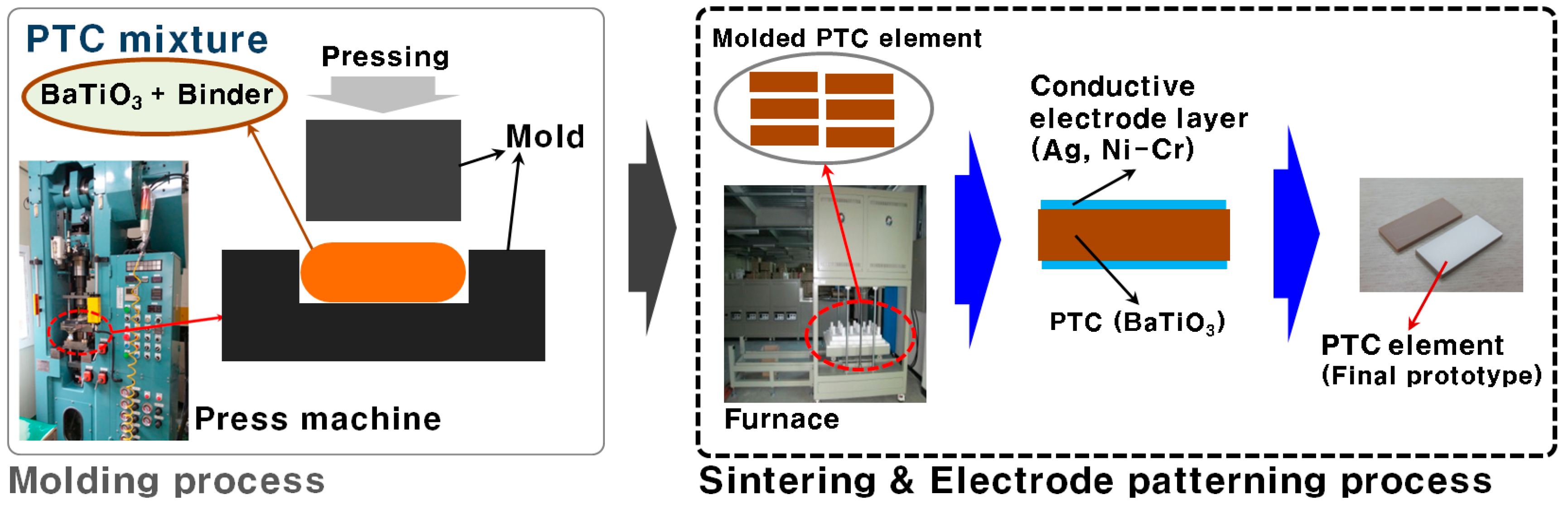
The PTC element was manufactured by forming a structure stacked with electrode layers to transmit power to semiconductive ceramic materials (
Figure 1). The technical development of the key processes for the element, namely sintering and electrode production, are detailed herein.
2.1. Sintering
The outer component of the PTC element for heating was manufactured from a compound containing barium titanate (BaTiO
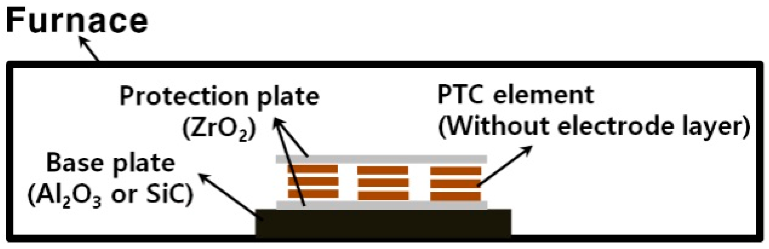
3), additional raw materials, and binder using a press device. Subsequently, the component was sintered in a furnace of at least 1300 °C to combine the compounds and increase its rigidity. The surface flatness of the plate-type element may deteriorate because of thermal deformation. However, the PTC elements for heaters must smoothly conduct heat through contact. Therefore, the temperature distribution uniformity of each PTC element must be ensured inside the furnace to enhance the surface flatness of the PTC elements during sintering. Appropriate plates were used for layering inside the furnace (
Figure 2) to minimize the distortion of the PTC element during sintering. Silicon carbide (SiC), which has a high thermal conductivity, was used as the material for the base plate to enhance the temperature distribution uniformity within the furnace. The SiC base plate also minimized bending and thickness variations by further equalizing the PTC element’s sintering temperature distribution.
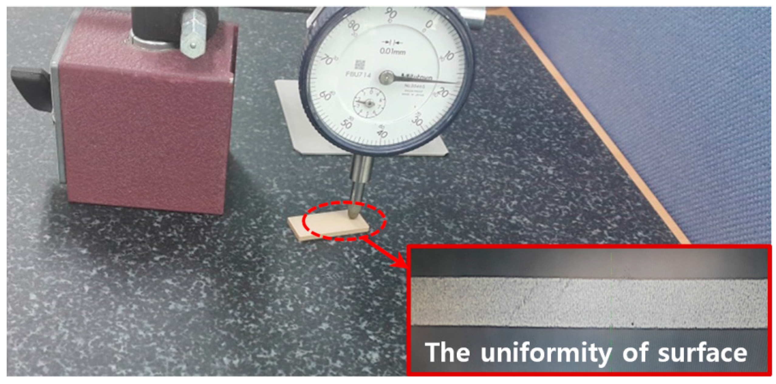
After sintering, the flatness and thickness variations of the PTC elements were measured (
Figure 3).
Table 1 lists the characteristics for each sintering process and the corresponding measurement results. When SiC was used as the base plate material, thickness variation reduced by approximately 60% compared with that obtained when aluminum oxide (Al
2O
3) was used; this result is indicative of the enhanced flatness of the PTC elements.
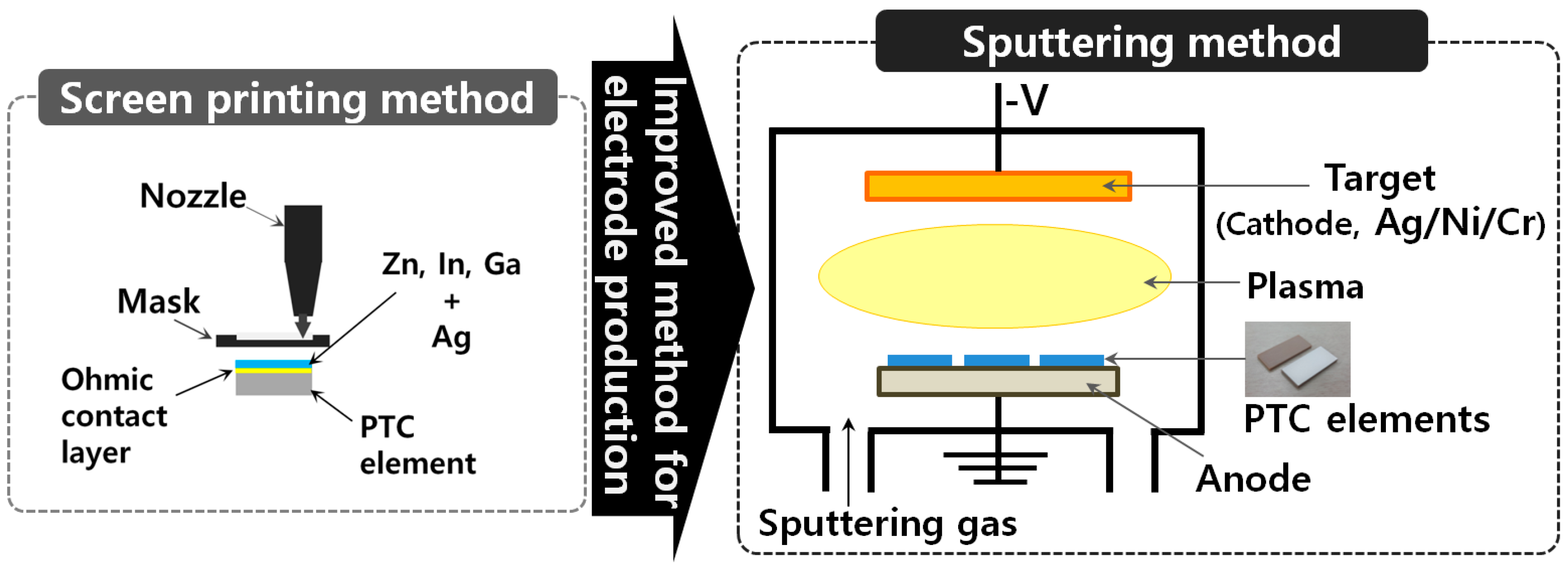
2.2. Electrode Production
Producing electrodes on the element surface is the most critical procedure in the manufacturing of PTC elements for heaters. To enhance element performance by improving contact between materials and to reduce the cost of the base materials in the electrode layer, this study actively applied the sputtering method instead of the existing screen printing method as shown in
Figure 4.
Table 2 details the specifications of the sputtering equipment. The electrode layer inputs electric energy into the PTC element. The performance and durability of the electrode is dependent on the characteristics of its core because it is formed at the surface, where the heater’s thermal energy is released. Electrode layers must be adequately thick (at least 10 μm) to withstand the voltage induced during screen printing. The characteristics of electrode layers composed of metallic materials (e.g., Ag and Al) differ from those composed of ceramic materials (e.g., BaTiO
3).
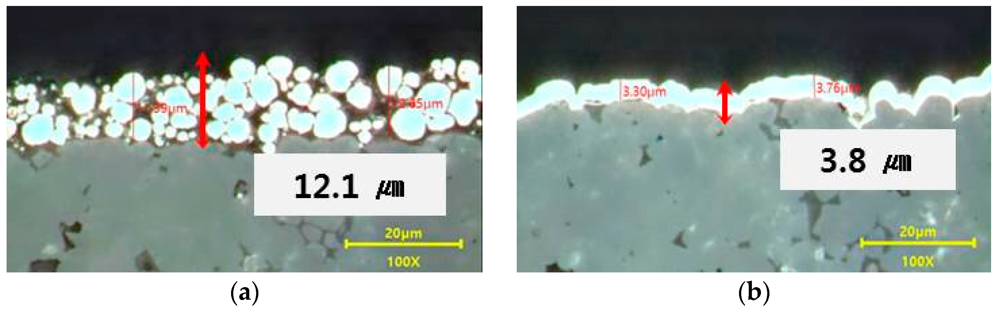
Figure 5 presents the cross-sections of the PTC elements manufactured through the existing screen printing method and the new sputtering method. Compared with screen printing, the sputtering method reduced electrode material use by approximately 69%. Moreover, contact uniformity of the electrode improved.
3. Performance Characteristics of the PTC Element
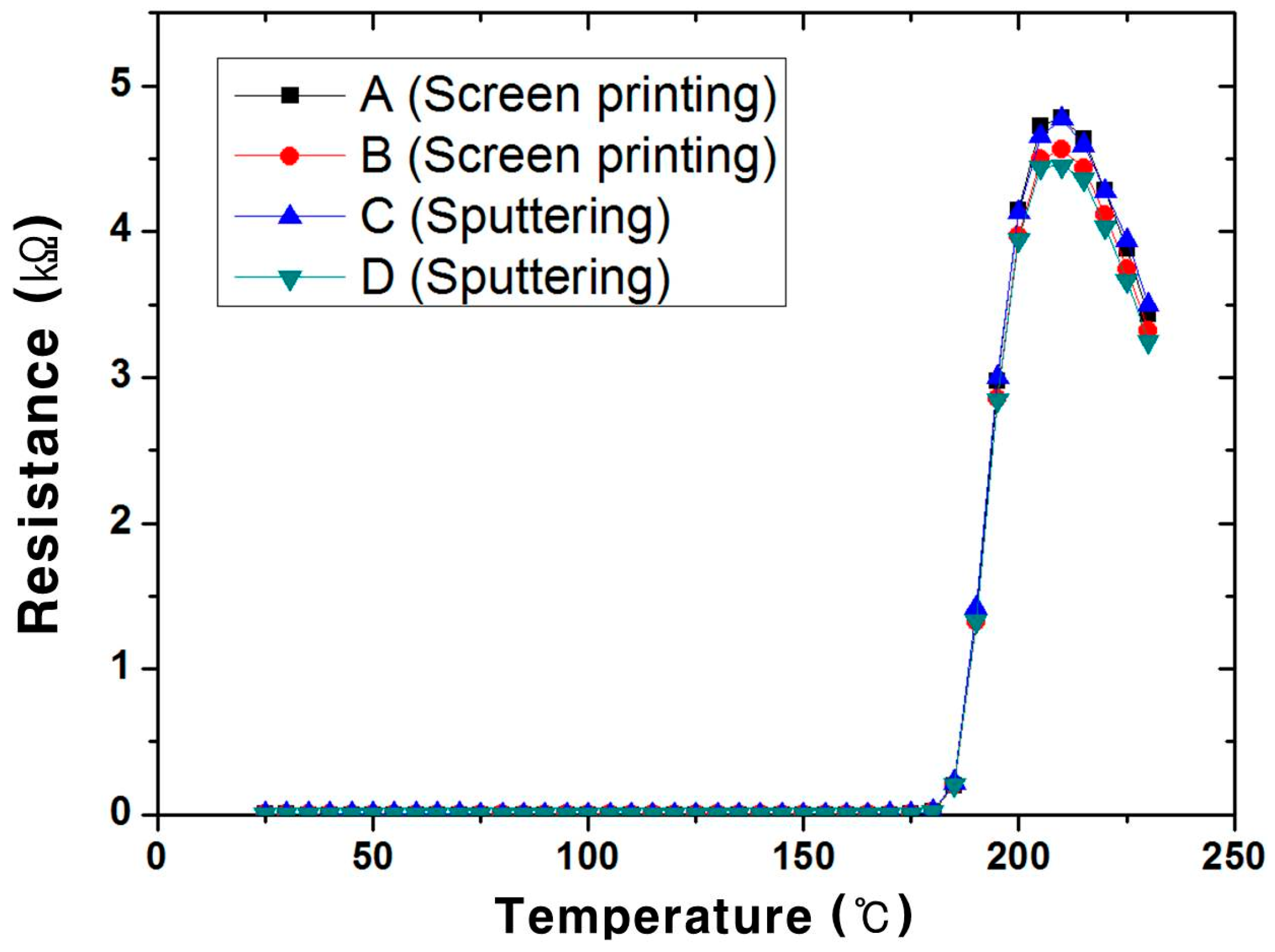
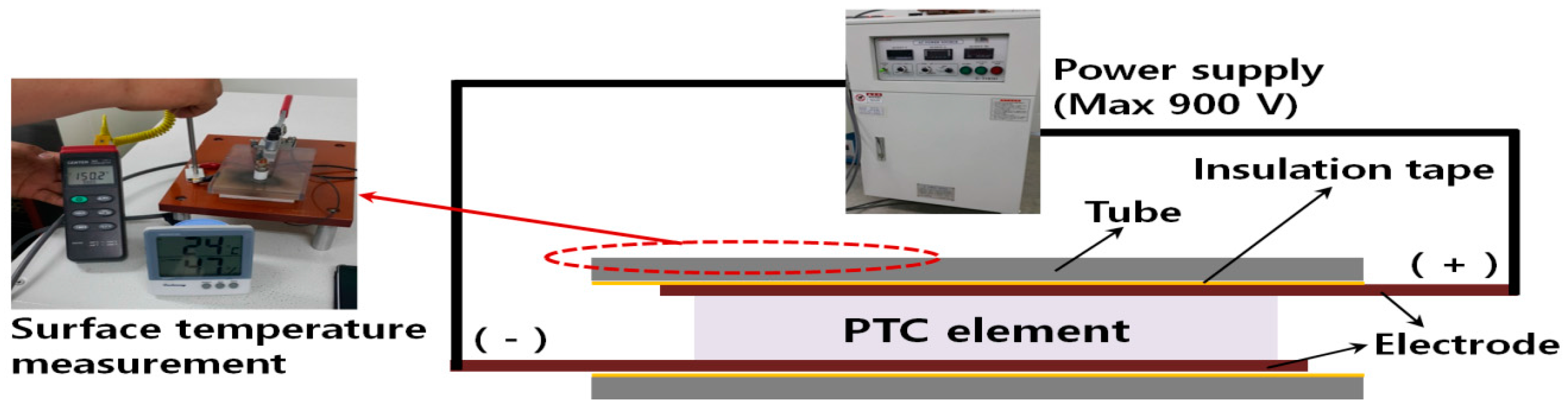
The variations in the resistance of the high-voltage PTC element prototypes manufactured through both electrode production processes were measured as a function of temperature by using the experimental devices shown in
Figure 6. The resulting characteristic curves are presented in
Figure 7 and summarized in
Table 3. The temperature at which resistance sharply increases is called the switching temperature or the Curie temperature (
Tc). It is the most representative parameter of any temperature-resistance characteristic curve and is generally defined as the temperature at which the resistance is two times the minimum resistance or the resistance at the reference temperature (25 °C). The operating
Tc range during sputtering (~175 °C) is almost equal to that during screen printing, which indicates that proposed approach can realize the operation range required for EV heating. Moreover, the temperature-resistance characteristics of the prototype fabricated through sputtering (prototypes C and D in
Table 3) are similar to those fabricated through screen printing (prototypes A and B).
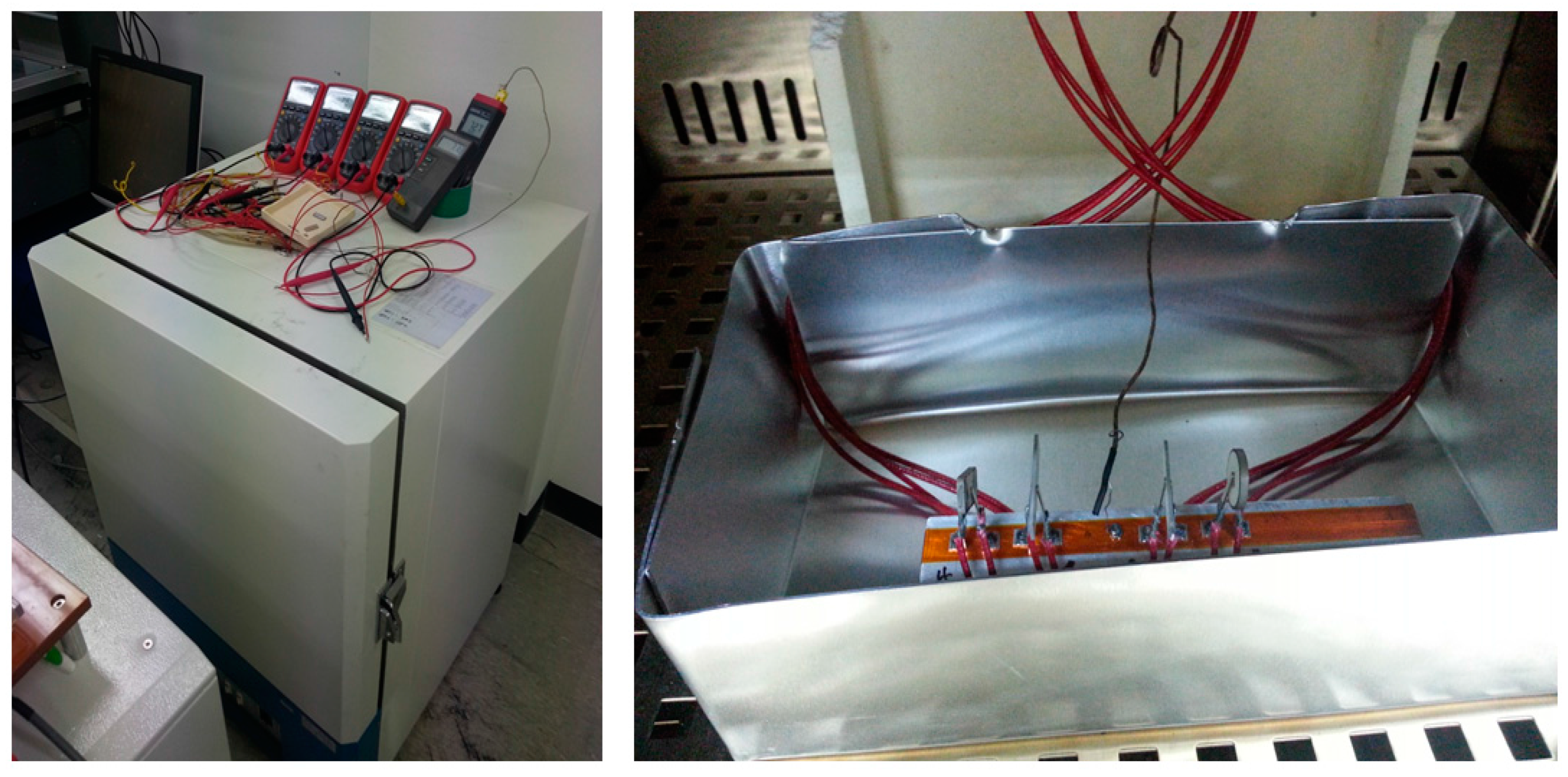
A device to estimate the allowable voltage and heat-generating temperature was fabricated (
Figure 8) to examine the improvements in surface solidity, electrode layer contact, and PTC element surface uniformity resulting from the thin-film electrode production process. Power sockets in contact with both sides of the PTC element were inserted within the Al contact tube and connected to the power supplier to permit power.
The allowable voltage was estimated at room temperature (25 ± 1 °C). Voltages of 800 and 850 V were applied for more than 300 s. The results are summarized in
Table 4. At the reference voltage of 800 V, the high-voltage PTC element prototypes did not exhibit any damages that could be seen with the naked eye. Furthermore, resistance variation was less than 10%, confirming that the prototypes meet the performance requirements for use in EV heaters.
A contact thermometer was used to measure the element’s surface heat temperature at room temperature and 330 or 350 V. The results are summarized in
Table 5. The measured surface heat temperatures were approximately 170 °C, which is the target temperature at 300 V for use in EV heaters.
4. Performance and Reliability of the PTC Heater
4.1. Heating Performance
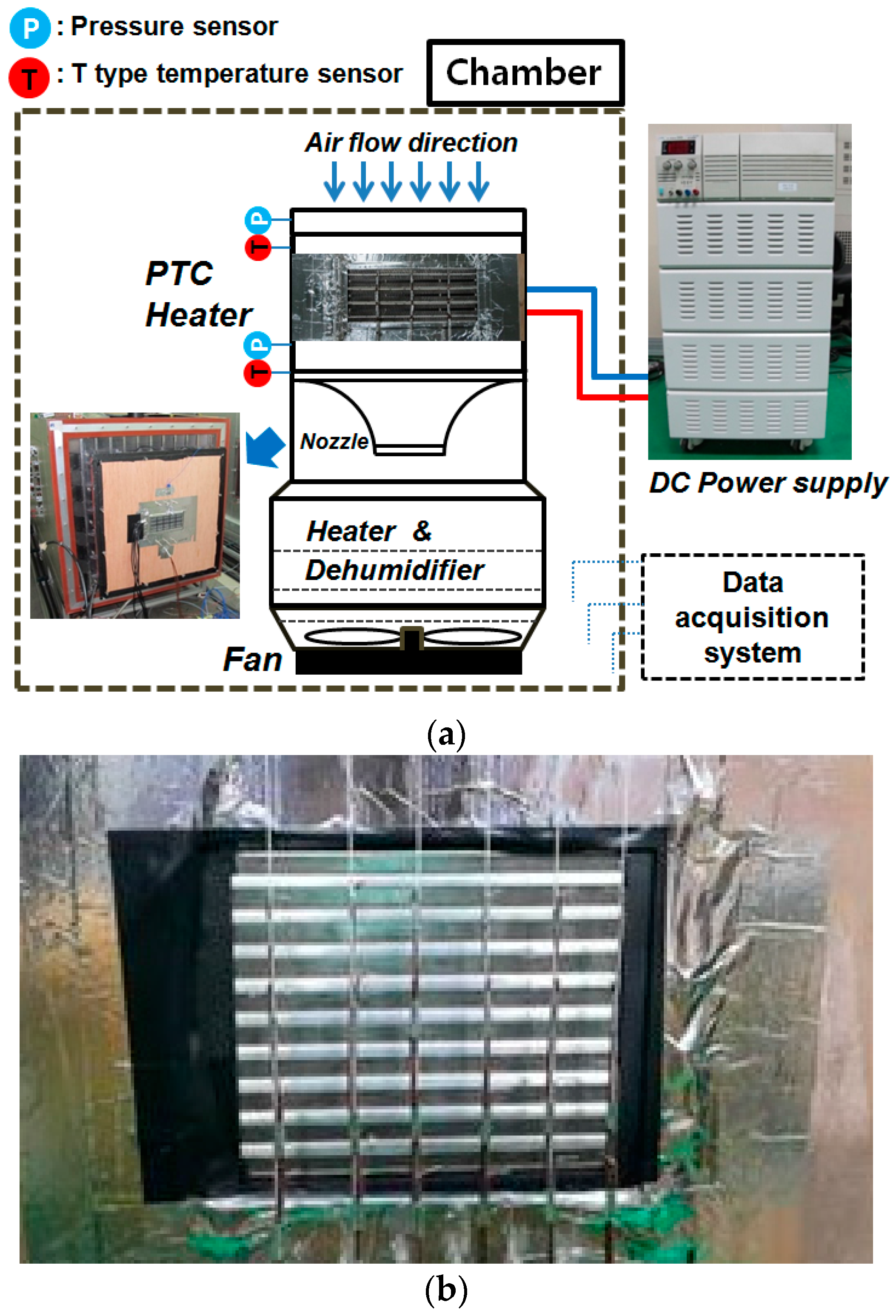
An electric heater was manufactured to evaluate the performance of the developed PTC element as a heating system.
Figure 9 presents the schematic design and a photograph of the test device used to measure the heating capacity, efficiency, and pressure drop of the high-voltage heater. The temperature of the inlet and outlet air from the wind tunnel device was measured at 24 different locations using a ±0.1 °C–resolution T-type thermocouple. Temperature and pressure data were collected using a data logger (Gantner) under the following experimental conditions: input power voltage of 330 V, inlet air temperature of 0 °C, and inlet air flow rate of 300 kg/h. These factors mirror the characteristics of the air volume exiting a vehicle’s Heating, Ventilation and Air Conditioning (HVAC) system blower during winter.
Heat transfer by air, power consumption, and pressure drop were measured by evaluating the performance of the four high-voltage prototype heaters. Efficiency was defined as the ratio of the heating capacity of the heater to its power consumption (Equation (1)). The results are summarized in
Table 6. The heating capacity and efficiency were on average 4.63 kW and 0.952, respectively, thereby meeting the performance requirements for use as electric heaters in EV heating systems. The pressure drop was 82.8 Pa on average, which is acceptable.
4.2. Reliability
Vibration and thermal shock test reliability tests were conducted in compliance with the relevant test conditions for PTC heaters (IEC60068-2-6 and IEC60068-2-14, respectively).
Table 7 and
Table 8 present the heating performance results before and after the vibration and thermal shock reliability tests, respectively. After the vibration and thermal shock tests, the heating performance of the prototype heaters decreased by a maximum of 6.1% and 5.3%, respectively, which is much less than that allowed (10%). Moreover, after the reliability tests, the overall performance of the prototype heater reduced by only 5%. Overall, these results prove the high reliability of the developed prototypes.
5. Conclusions
This study improved the sintering process to enhance surface uniformity in the manufacturing process of PTC elements for use in EV heating systems. An electrode production process using thin-film sputtering deposition was applied to ensure the heating performance of PTC elements and reduce electrode material use. In addition, a heater for an EV heating system was manufactured using the developed high-voltage PTC elements to verify their performance. The study conclusions are as follows:
(1) The proposed method realized an electrode layer of uniform thickness not exceeding 3.8 μm and reduced electrode material use by approximately 69%.
(2) The allowable voltage and surface heat temperature of the high-voltage PTC elements developed with the thin-film electrode were 800 V and 172 °C, respectively, which is adequate for use in high-voltage heaters.
(3) The results of vibration and thermal shock testing were within the standard range, confirming that the developed heater was adequately reliable for use in EV vehicles.
Acknowledgments
This study was performed as a part of the Energy Technology Development project sponsored by the Ministry of Trade, Industry and Energy and was supported by the 2016 Yeungnam University Research Grant. In addition, support from E-Gun Technology is greatly appreciated.
Author Contributions
Sung Chul Kim and Yoon Hyuk Shin organized the overall experimental evaluations and result analysis. Seung Ku Ahn commented on the results and conclusions. All the authors also reviewed the manuscript.
Conflicts of Interest
The authors declare no conflict of interest.
Nomenclature
| Cp | specific heat of air (J/kg·K) |
| I | current (A) |
| mass flow rate of air (kg/s) |
| Tc | Curie temperature (°C) |
| Ti | inlet air temperature (°C) |
| To | outlet air temperature (°C) |
| V | input voltage (V) |
| η | energy efficiency |
References
- Yokoyama, A.; Osaka, T.; Imanishi, Y.; Sekiya, S. Thermal management system for electric vehicles. SAE Int. 2011, 4. [Google Scholar] [CrossRef]
- Lee, J.T.; Kwon, S.J.; Lim, Y.; Chon, M.S.; Kim, D. Effect of air-conditioning on driving range of electric vehicle for various driving modes. SAE Int. 2013. [Google Scholar] [CrossRef]
- Ahn, J.H.; Kang, H.; Lee, H.S.; Jung, H.W.; Baek, C.; Kim, Y. Heating performance characteristics of a dual source heat pump using air and waste heat in electric vehicles. Appl. Energy 2014, 119, 1–9. [Google Scholar] [CrossRef]
- Ahn, J.H.; Kang, H.; Lee, H.S.; Kim, Y. Performance characteristics of a dual-evaporator heat pump system for effective dehumidifying and heating of a cabin in electric vehicles. Appl. Energy 2015, 146, 29–37. [Google Scholar] [CrossRef]
- Kim, S.C.; Kim, M.S.; Hwang, I.C.; Lim, T.W. Heating performance enhancement of a CO2 heat pump system recovering stack exhaust thermal energy in fuel cell vehicles. Int. J. Refrig. 2007, 30, 1215–1226. [Google Scholar] [CrossRef]
- Park, S.M.; Kim, S.D.; Chun Suk, J.; Lee, C.W.; Kim, J.W.; Jung, S.W. Development of intelligent-controlled high voltage PTC for eco-friendly EV. In Proceedings of the Spring Conference of KSME, Seoul, Korea, 2–3 June 2011; pp. 144–147.
- Shin, Y.H.; Sim, S.; Kim, S.C. Performance Characteristics of a Modularized and Integrated PTC Heating System for an Electric Vehicle. Energies 2016, 9, 18. [Google Scholar] [CrossRef]
- Kim, K.Y.; Kim, S.C.; Kim, M.S. Experimental studies on the heating performance of the PTC heater and heat pump combined system in fuel cells and electric vehicles. Int. J. Automot. Technol. 2012, 13, 971–977. [Google Scholar] [CrossRef]
- Cen, J.; Wang, D. The metallization of PTC ceramic by magnetron sputtering. Phys. Procedia 2012, 32, 482–486. [Google Scholar] [CrossRef]
- Cheng, W.; Yuan, S.; Song, J. Studies on preparation and adaptive thermal control performance of novel PTC (positive temperature coefficient) materials with controllable Curie temperatures. Energy 2014, 74, 447–454. [Google Scholar] [CrossRef]
© 2016 by the authors; licensee MDPI, Basel, Switzerland. This article is an open access article distributed under the terms and conditions of the Creative Commons Attribution (CC-BY) license (http://creativecommons.org/licenses/by/4.0/).


