Article

Multi-Scale Assessment of Transformer Inrush Suppression by Pre-Magnetization Based on Clarke–Wavelet Energy Spectrum

1
Jiangsu Electric Power Company, Nanjing 210024, China
2
State Grid Guanyun Power Supply Company, Lianyungang 222000, China
3
State Key Laboratory of Smart Power Distribution Equipment and System, Hebei University of Technology, Tianjin 300401, China
4
Key Laboratory of Electromagnetic Field and Electrical Apparatus Reliability of Hebei Province, Hebei University of Technology, Tianjin 300401, China
*
Author to whom correspondence should be addressed.
Energies 2026, 19(9), 2070; https://doi.org/10.3390/en19092070
Submission received: 20 March 2026 / Revised: 14 April 2026 / Accepted: 22 April 2026 / Published: 24 April 2026

Abstract

Transformers serve as crucial hubs for power transmission, but during no-load energization, the nonlinear magnetization of their cores frequently induces extreme magnetizing inrush currents. Current suppression methods encounter challenges regarding transient feature extraction and excessive circuit complexity. To overcome these limitations, this study develops a high-fidelity model of a 100 kVA transformer using MATLAB/Simulink to investigate the interaction between residual flux and the closing angle. Extensive simulations were executed across a closing phase angle range of 0° to 360° and a residual flux domain of −0.8 p.u. to 0.8 p.u. Furthermore, this study utilizes Wavelet and Clarke transforms to extract characteristic parameters and quantitatively analyze the transients within the energy domain, enabling a multi-scale assessment of the mitigation efficacy based on these extracted features. The analytical results demonstrate that an optimal pre-magnetization distribution of −0.8 p.u. for Phase A, 0 p.u. for Phase B, and 0.8 p.u. for Phase C, coupled with a target closing angle of 330°, achieves the best suppression. This strategy strictly clamps the peak inrush current to 1.5 times the rated current, significantly outperforming conventional demagnetization alone. Consequently, this highly pronounced mitigation effect provides robust support for reliable transformer protection and overall power grid security.

1. Introduction

Transformers are the core hubs of power transmission in electrical grids [1]. During no-load energization, the nonlinear magnetization and hysteresis of the ferromagnetic core often induce magnetizing inrush currents with amplitudes up to 6–8 times the rated current. These extreme currents not only impose severe mechanical and electrodynamic stresses on winding insulation, but also cause bus voltage sags, harmonic pollution, and maloperation of differential protection relays [2].
The generation of the inrush current is intrinsically linked to core residual flux, and existing studies mainly focus on two directions: residual flux elimination and precise measurement. For demagnetization, effective rapid in situ demagnetization methods for protective current transformers (CTs) have been developed [3], and scholars have further proposed optimized strategies such as the flux-controlled variable-frequency constant-voltage method [4], energy storage oscillation-based elimination scheme [5], and alternating-polarity DC voltage method for large power transformers [6]. For residual flux measurement, Huo et al. provided a comprehensive review of global research progress on power transformer core residual flux detection methods [7]; among specific technical routes, magnetizing inductance-based methods [8,9,10], transient signal-based detection technologies [11,12], and fluxgate theory-based in situ detection for protective CTs [13] have been widely studied. However, existing residual flux detection and demagnetization schemes predominantly rely on offline operations or intricate hardware circuits, thereby exhibiting notable deficiencies in both economic viability and technological maturity.
Inrush current suppression research mainly includes three technical routes, each with inherent limitations. First, as a classical method, point-on-wave controlled switching has been optimized in recent years [14,15,16], but it has two core bottlenecks: most studies only optimize the single closing angle of one phase, ignoring the constraint that the sum of three-phase residual flux is zero, making it impossible to minimize the flux deviation of all three phases simultaneously; meanwhile, it has extremely high requirements for residual flux measurement accuracy, with poor anti-interference performance in field operation. Second, power electronic-based active intervention schemes [17,18,19] can achieve good suppression effects, but require additional high-power devices, which greatly increases circuit complexity and cost, and is difficult to popularize in 10 kV distribution transformers. Third, customized strategies for new power system scenarios [20,21,22,23] have expanded application boundaries, but their scenario-specific design is not applicable to conventional distribution transformers.
In terms of inrush current identification for transformer protection, research has shifted from traditional waveform analysis to the integration of advanced signal processing and artificial intelligence algorithms. Scholars have proposed Clarke–Wavelet-based time-domain differential protection [24,25], discrete energy separation algorithms [26], equivalent statistics-based feature extraction methods [27], and data-driven intelligent identification methods [28,29], which have improved the reliability of inrush and fault identification. Concurrently, targeting the sympathetic inrush-induced maloperation of adjacent generator differential protection, recent research has proposed an enhanced restraint strategy [30], further improving the overall protection framework for transformers. However, AI-based data-driven methods rely heavily on high-quality samples for model training, with poor generalization performance in unseen operating conditions. In contrast, the Clarke–Wavelet energy spectrum method adopted in this paper is driven by the physical mechanism of inrush transients, requires no data pre-training, and has higher real-time performance and anti-interference ability, which can effectively compensate for the shortcomings of AI-based methods in engineering applications.
To address the above limitations, this paper conducts a multi-scale quantitative assessment of the transformer inrush current suppression effect by pre-magnetization based on Clarke–Wavelet energy spectrum, and develops an engineering-applicable pre-magnetization scheme. The core work of this paper is as follows:
(1)
A high-fidelity 100 kVA transformer simulation model is built in MATLAB R2023b/Simulink, and a full-traversal parametric sweep is carried out with the closing phase angle (0–360°) and core residual flux (−0.8 p.u.–0.8 p.u.) as variables. On this basis, three typical operating conditions are selected for comparative analysis, and the peak amplitude and time-domain waveform distortion characteristics of the magnetizing inrush current under different conditions are quantitatively characterized.
(2)
Combined with Clarke transform and Wavelet transform, the multi-scale feature extraction of the inrush current is completed: the DC component and second to fifth harmonic amplitude of the inrush waveform are extracted through multi-resolution analysis, and the time-domain differential energy spectrum of the inrush transient is constructed based on the high-frequency detail coefficients of wavelet decomposition, realizing the quantitative comparison of transient energy characteristics under different working conditions.
(3)
Based on the comprehensive comparative analysis of the time-domain peak, frequency-domain harmonic and energy-domain spectrum characteristics, it is verified that the inrush current suppression effect of pre-charging reasonable residual flux in the core is significantly better than the traditional full demagnetization scheme. On this basis, the optimal pre-magnetization residual flux distribution of [−0.8, 0, 0.8] p.u. and the optimal matching closing angle of 330° are determined, and a simple and easy-to-implement three-phase pre-magnetization circuit is proposed for engineering application.

2. Transformer Inrush Current Suppression Strategy

Based on a three-phase transformer model, this chapter conducts no-load energization simulations to investigate the suppression of inrush currents via core pre-magnetization. Subsequently, transient feature extraction is performed utilizing the Wavelet and Clarke transforms to comprehensively evaluate the mitigation efficacy of the proposed pre-magnetization strategy.

2.1. Mechanism of Inrush Current Generation

Transformer cores are typically constructed from laminated ferromagnetic materials characterized by high magnetic permeability and low core loss. Magnetic materials inherently exhibit a tendency to retain their magnetization, wherein the variation in the magnetic flux density B invariably lags behind that of the magnetic field intensity H. This phenomenon is formally defined as magnetic hysteresis.
The no-load energization of a transformer is fundamentally a transient magnetization process of its core [31]. The intensity of the internal magnetic field is established by the magnetizing current, whose amplitude and phase exhibit periodic temporal variations governed by the winding terminal voltage. Consequently, from a macroscopic perspective, the dynamic behavior of the main magnetic flux within the transformer core is predominantly dictated by the excitation voltage applied across the windings.
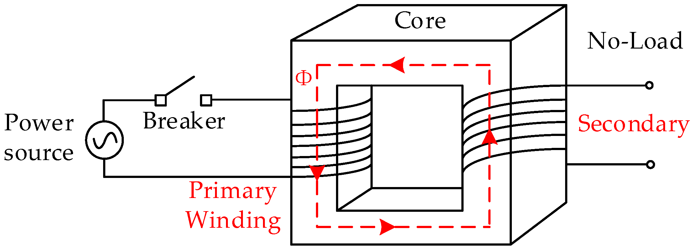
Taking a single-phase transformer as an illustrative example, as shown in Figure 1, the governing loop equation derived from its no-load equivalent circuit model is expressed as follows:
U 1 = i m R 1 + N 1 d Φ d t
where U1 represents the instantaneous excitation voltage applied to the primary winding, im is the instantaneous magnetizing current, R1 denotes the equivalent resistance of the primary winding loop, N1 is the number of turns in the primary winding, and Φ represents the main magnetic flux within the transformer core.
The excitation voltage applied to the transformer can be expressed as:
u t = U m sin ω t + α
where u(t) is the instantaneous voltage value over time, Um specifies the peak amplitude of the excitation voltage, ω denotes the angular frequency of the power source, and α represents the initial closing phase angle at the exact instant of energization.
Substituting Equation (2) into Equation (1), and using the relationship between excitation current and magnetic flux i m = N 1 Φ L 1 , the differential equation governing the dynamic characteristics of magnetic flux can be obtained as follows:
U m sin ω t + α = N 1 R 1 L 1 Φ + N 1 d Φ d t
where L1 represents the equivalent magnetizing inductance of the primary winding.
Solving this differential equation yields the total core magnetic flux. The complete solution consists of a steady-state particular solution and a transient homogeneous solution:
Φ ( t ) = Φ m cos ( ω t + α ) + ( Φ m cos α + Φ r ) e R 1 t / L 1
In this solution, Φ(t) represents the instantaneous magnetic flux over time, Φm is the peak steady-state magnetic flux, and Φr denotes the initial remanent flux present in the core prior to energization.

2.2. Suppression Mechanism of Pre-Magnetization

As discussed in the above regarding the mechanism of inrush current generation, when a single-phase transformer is energized under no-load conditions, the core magnetic flux is predominantly determined by the initial closing phase angle α and the remanent flux Φr.
However, during the no-load energization of a three-phase transformer, the generation mechanism of the inrush current becomes significantly more complex due to the phase displacements among the three-phase voltages and currents. Specifically, assume that arbitrary remanent fluxes exist in the three-phase cores, denoted as ΦAr, ΦBr, and ΦCr, which satisfy the conditions |ΦAr| ≥ |ΦCr|, |ΦBr| ≥ |ΦCr|, and ΦAr > 0. The three-phase prospective fluxes are represented by ΦAp(t), ΦBp(t), and ΦCp(t), respectively (expressed in per-unit values with the transformer’s rated flux as the base value), and the phase-A voltage serves as the reference voltage, uAG.
u A G = U m sin ( ω t ) Φ A p ( t ) = Φ m sin ω t π / 2 Φ B p ( t ) = Φ m sin ω t + 5 π / 6 Φ C p ( t ) = Φ m sin ω t + π / 6
Because the three-phase remanent fluxes in the core differ, no single instant simultaneously fulfills ΦAr = ΦAp, ΦBr = ΦBp, and ΦCr = ΦCp. The absolute deviation between the prospective and remanent fluxes for each phase is obtained as:
Δ Φ A = Φ A p ( t ) Φ A r Δ Φ B = Φ B p ( t ) Φ B r Δ Φ C = Φ C p ( t ) Φ C r
Specifically, for a standard three-phase three-limb transformer core, according to Kirchhoff’s law for magnetic circuits (the principle of magnetic flux continuity), the algebraic sum of magnetic fluxes entering a closed magnetic node must be zero. Neglecting the leakage flux through the air, this physical restriction applies not only to the instantaneous flux during operation but also strictly governs the static residual flux distribution after de-energization. Therefore, the three-phase remanent fluxes ΦAr, ΦBr, and ΦCr are subject to the following physical constraint:
Φ A r   + Φ B r   + Φ C r   = 0
Therefore, there exists an optimal energization instant, which minimizes the sum of the magnetic flux deviations across all three phases. Further analysis indicates that this optimal instant coincides with the moment when the remanent flux of the phase exhibiting the lowest remanence level equals its prospective flux. Specifically, when the remanent flux of this minimum-remanence phase (e.g., Phase C) matches its prospective flux, and the flux deviations in the other two phases (Phases A and B) are identical and relatively minor, the magnetic flux in Phase C directly transitions into steady-state operation. Meanwhile, the fluxes in Phases A and B closely approximate their respective prospective trajectories. Consequently, no magnetizing inrush current is induced upon energization.

3. Clarke–Wavelet Transient Feature Extraction and Energy Spectrum Derivation

In this section, the Wavelet and Clarke transforms are employed for transient feature extraction. By comparing the current amplitudes up to the fifth harmonic alongside the energy spectra, the mitigation efficacy is comprehensively evaluated.

3.1. Clarke Transform-Based Modal Decoupling of Differential Currents

To eliminate the zero-sequence current and reduce the computational dimensionality of the three-phase system, a power-invariant Clarke transformation matrix is employed to map the three-phase differential currents (ia,diff, ib,diff, ic,diff) into a stationary orthogonal coordinate system.
To eliminate the zero-sequence current interference and significantly reduce the computational dimensionality of the three-phase system, a power-invariant Clarke transformation matrix is employed. This transformation maps the three-phase differential currents (iA,diff, iB,diff, iC,diff) from the stationary A-B-C coordinate system into an orthogonal α-β-0 coordinate system. The discrete mathematical expression is formulated as:
i α , d i f f [ n ] i β , d i f f [ n ] i 0 , d i f f [ n ] = 2 3 1 1 2 1 2 0 3 2 3 2 1 2 1 2 1 2 i A , d i f f [ n ] i B , d i f f [ n ] i C , d i f f [ n ]
where n represents the discrete sampling time-step index; iA,diff [n], iB,diff [n], and iC,diff [n] are the discrete sampled values of the differential currents for phases A, B, and C, respectively, at the n-th sampling point; and iα,diff [n], iβ,diff [n], and i0,diff [n] denote the α-mode, β-mode, and zero-sequence components obtained after the Clarke transformation, respectively.
Through this decoupling process, the zero-sequence component is completely isolated. Since the α-mode component, iα,diff [n], perfectly preserves the abundant high-frequency transient features inherent in the original signals, it is exclusively selected as the characteristic baseline for all subsequent analyses.

3.2. Wavelet-Based High-Frequency Transient Feature Extraction

To precisely capture the singularities at the exact instant of an inrush current or an internal fault, the Daubechies 4 (db4) mother wavelet is selected to perform multi-scale feature extraction on the α-mode current. Characterized by its excellent orthogonality and compact support, the db4 wavelet exhibits exceptional sensitivity to abrupt transient changes.
By passing the α-mode differential signal iα,diff [n] through the high-pass filter h[k] associated with the db4 wavelet, the first-level high-frequency detail coefficient d1,diff[n] is derived via discrete convolution:
d 1 , d i f f [ n ] = k h [ k ] i α , d i f f [ n k ]
where h[k] is the discrete impulse response coefficient of the high-pass decomposition filter corresponding to the db4 mother wavelet; k is the translation time index of the discrete convolution operation; and d1,diff[n] is the extracted first-level high-frequency transient detail coefficient of the α-mode differential current.
Similarly, by applying the identical extraction procedure to the restraint current of the transformer, the high-frequency restraint detail coefficient d1,rest[n], which is utilized for the subsequent closed-loop evaluation, can be obtained.

3.3. Energy Spectrum Construction and Closed-Loop Evaluation Criteria

Direct utilization of high-frequency wavelet coefficients as protection criteria may lead to maloperation due to high-frequency noise spikes. To enhance the anti-interference robustness of the algorithm, Parseval’s theorem is introduced to convert the discrete sequence of high-frequency detail coefficients into an energy integral over a sliding time window.
Defining a sliding data window with a width of Tw, the discrete summation formulas for the time-domain differential operating energy spectrum Eop[n] and the restraint energy spectrum Eres[n] are given as follows:
E o p [ n ] = k = n T w + 1 n d 1 , d i f f [ k ] 2
E r e s [ n ] = k = n T w + 1 n d 1 , r e s [ k ] 2
where Tw denotes the sliding data window length, which is typically set to be greater than or equal to the filter length to ensure stable transient capture while filtering out instantaneous noise spikes. Eop[n] is the time-domain differential operating energy calculated at the n-th sampling instant. Eres[n] is the time-domain restraint energy calculated at the n-th sampling instant. d1,diff[k] and d1,res[k] are the db4 wavelet high-frequency detail coefficients of the operating differential current and the restraint current, respectively, at the k-th sampling point within the current time window.
The closed-loop evaluation criteria are defined as follows: if Eop[n] < K· Eres[n], the event is identified as a smooth energization or normal external event (indicating successful mitigation). Conversely, if the energy value crosses both boundaries simultaneously, it indicates severe core saturation or an internal fault. The issuance of a protection trip command must simultaneously satisfy the following two energy-based operating equations:
E o p [ n ] > E t h E o p [ n ] > K E r e s [ n ]
Within these criteria, Eth is the threshold energy (experimentally set to 0.05 based on quantitative evaluation of critical internal faults) designed to overcome background noise and steady-state imbalances, while K is the restraint coefficient (conservatively set to 0.5) that provides security against high-frequency unbalanced energy during external faults and current transformer saturation.
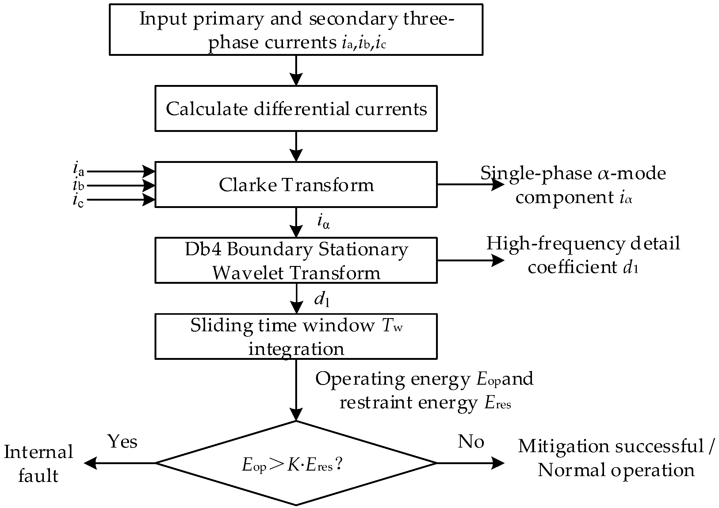
The overall flowchart of the evaluation methodology is shown in Figure 2. During the energization transient, if the pre-magnetization collaborative control is executed successfully, the total flux transitions smoothly without current distortion, and the high-frequency sudden changes are minimal. Consequently, Eop[n] consistently approaches zero (Eop[n] < Eth), which is evaluated as a successful mitigation. Conversely, if Eop[n] exhibits a step-like surge and simultaneously crosses the dual boundaries of Eth and K · Eres[n], it accurately indicates severe core saturation caused by pre-magnetization failure or an internal transformer fault, thereby reliably triggering the circuit breaker to achieve a millisecond-level trip.

4. Simulation and Multi-Scale Analysis of Transformer Magnetizing Inrush Current

4.1. Simulation Model Development and Parametric Sweep Configuration

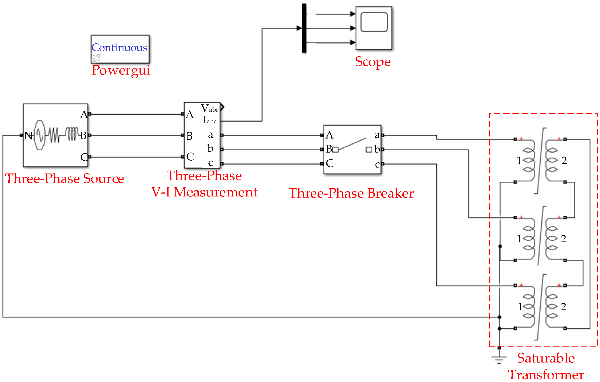
In this paper, a 10 kV/400 V three-phase distribution transformer is selected as the research object, whose core nameplate parameters are detailed in Table 1. First, a simulation model dedicated to characterizing the transient characteristics of the three-phase transformer magnetizing inrush current is developed based on the MATLAB/Simulink simulation platform, as illustrated in Figure 3.
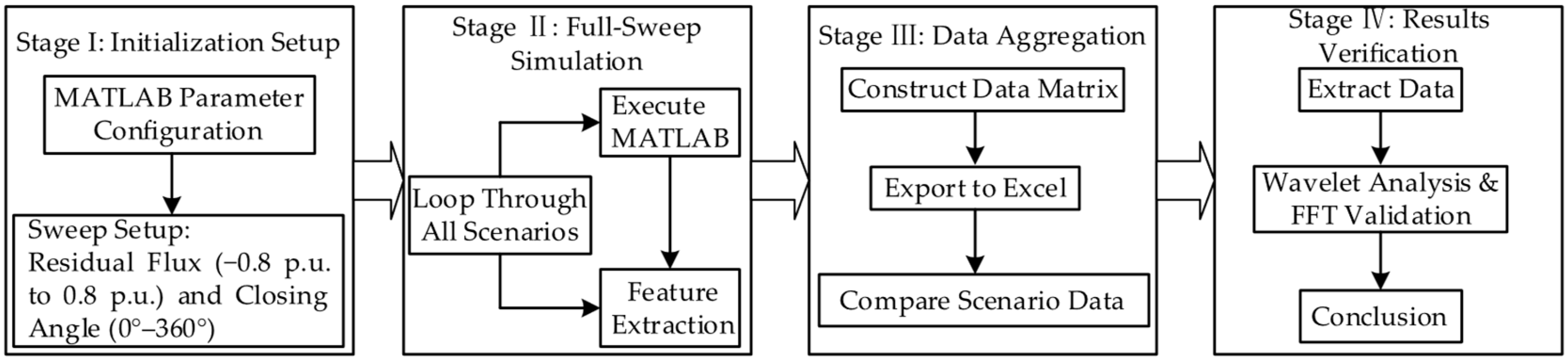
To systematically explore the influence law of core residual flux and closing phase angle on the magnetizing inrush current, parameter configuration of core simulation components including the transformer and equivalent power supply is implemented via MATLAB programming, and a two-variable full-traversal parametric sweep scheme is developed. With Equation (7) as the simulation constraint boundary, a full-range sweep of the closing phase angle is performed from 0° to 360° with a step of 1°, while the core residual flux is swept from −0.8 p.u. to 0.8 p.u. with a step of 0.2 p.u. The overall simulation process is illustrated in Figure 4.
For the simulation results under each parameter combination, the peak characteristics and full-cycle transient waveforms of the magnetizing inrush current are fully documented. On this basis, the variation law of magnetizing inrush current peaks under different operating conditions is first compared, and the amplitudes of each component from the DC component to the fifth harmonic component of the inrush waveform are then extracted through wavelet transform. Furthermore, the differential energy spectrum of the inrush current is extracted and quantitatively analyzed based on the combined Clarke transform and Wavelet transform algorithm. Finally, the optimal matching combination of the core residual flux range and closing phase angle for magnetizing inrush current suppression is identified.

4.2. Multi-Scale Transient Feature Analysis Under Various Energization Scenarios

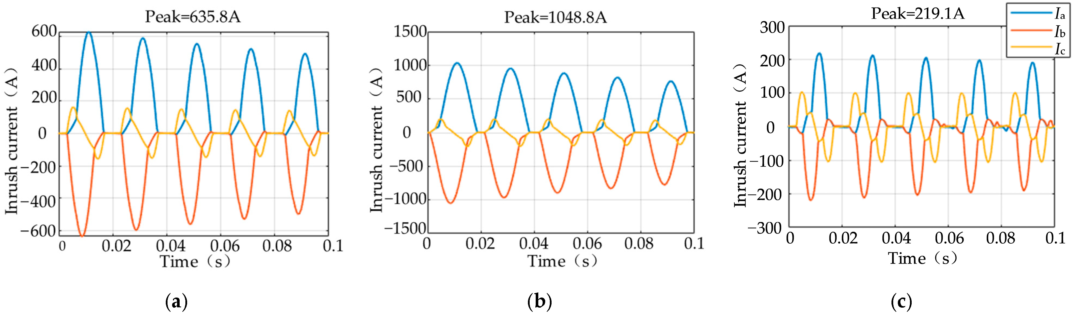
Based on the results of the two-variable full-traversal parametric combination of the closing phase angle and core residual flux, three groups of representative typical operating conditions are selected for comparative analysis of the current characteristics during the transient process of the magnetizing inrush current, with the results illustrated in Figure 5. Among them, Figure 5a displays the transient magnetizing inrush current waveform under the zero core residual flux reference operating condition; Figure 5b shows the waveform under the worst operating condition, which corresponds to a random combination of core residual flux and closing phase angle with the maximum magnetizing inrush current peak and the most severe transient distortion; Figure 5c presents the transient current waveform under the operating condition with the optimal core residual flux and closing phase angle matching for magnetizing inrush current suppression.
Figure 5 illustrates the transient simulation waveforms of the magnetizing inrush current under three typical operating conditions, in one-to-one correspondence with the three sets of control operating conditions selected in the preceding two-variable traversal analysis.
The first condition corresponds to the conventional technical approach for magnetizing inrush current suppression widely adopted in current power engineering, namely full core demagnetization. Simulation results demonstrate that even with the core fully demagnetized to the zero residual flux reference state, the transient peak of the no-load closing magnetizing inrush current still reaches 635.8 A, i.e., 4.4 times the rated current. This peak magnitude remains at a sufficiently high level to induce irreversible electromagnetic impact damage to the transformer winding insulation and equipment body.
In sharp contrast is the worst-case operating condition without parameter matching, corresponding to an unordered combination of random core residual flux and a random closing phase angle. The simulated peak magnetizing inrush current under this condition reaches as high as 1048.8 A, equivalent to 7.3 times the rated current. This extreme inrush not only exacerbates deep core saturation and winding vibration of the transformer, but also poses a critical threat to the insulation integrity of the transformer body and its long-term operational reliability.
Finally, the operating condition with the optimal magnetizing inrush current suppression performance is presented: in this condition, the three-phase core residual flux is accurately set to [−0.80, 0.00, 0.80] p.u., and no-load closing is completed at the closing phase angle of 330°. Transient waveform results confirm that the magnetizing inrush current is extremely significantly mitigated under this condition, with the peak magnitude strictly limited to less than 1.5 times the rated current. Comparative analysis of the three conditions clarifies the core law: accurately matching and retaining an appropriate amount of residual flux in the transformer core, rather than adopting the conventional full demagnetization to the zero residual flux scheme, achieves a superior suppression effect on the magnetizing inrush current.
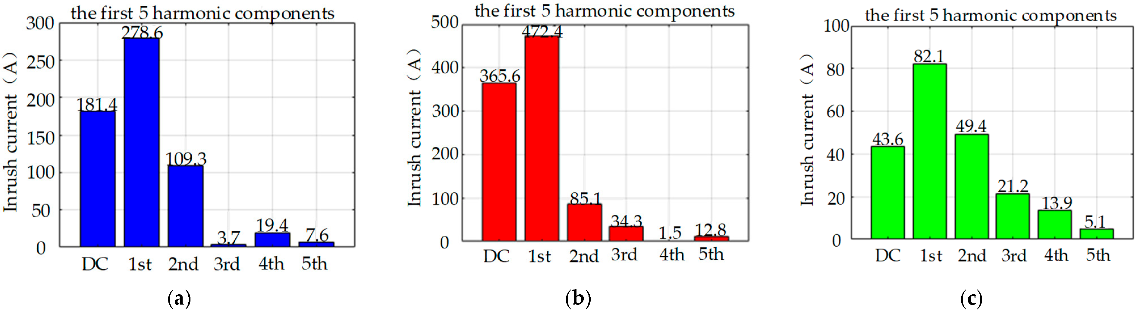
To quantitatively evaluate the transient distortion characteristics of the transformer energization current, wavelet transform is adopted to conduct multi-scale feature decomposition of current waveforms under three typical operating conditions. Through this method, the amplitude distributions from the DC component to the fifth harmonic are accurately extracted.
Quantitative spectral analysis results first show that under the conventional zero residual flux condition shown in Figure 6a, the mainstream engineering scheme for magnetizing inrush current suppression, the transient current still exhibits a significant DC offset accompanied by abundant harmonic components. In sharp contrast, under the worst-case operating condition corresponding to a random combination of the core residual flux and closing phase angle shown in Figure 6b, the transient current presents an extremely high DC offset and more severe harmonic distortion. Both phenomena confirm that the transformer core rapidly enters deep nonlinear saturation immediately upon energization, which directly induces extreme distortion of the magnetizing inrush current.
Finally, under the operating condition with accurately matched three-phase core residual flux and closing phase angle shown in Figure 6c, the fundamental amplitude of the energization current is significantly attenuated, while the DC component and all higher-order harmonics from the second to the fifth are comprehensively suppressed to near-negligible levels. Multi-dimensional comparative analysis of the DC and harmonic characteristics provides solid quantitative evidence that accurate matching and retention of appropriate core residual flux can effectively mitigate core saturation from its physical mechanism. As a result, the energization current maintains excellent sinusoidality, and realizes a smooth, low-distortion, impact-free transition to steady-state operation.
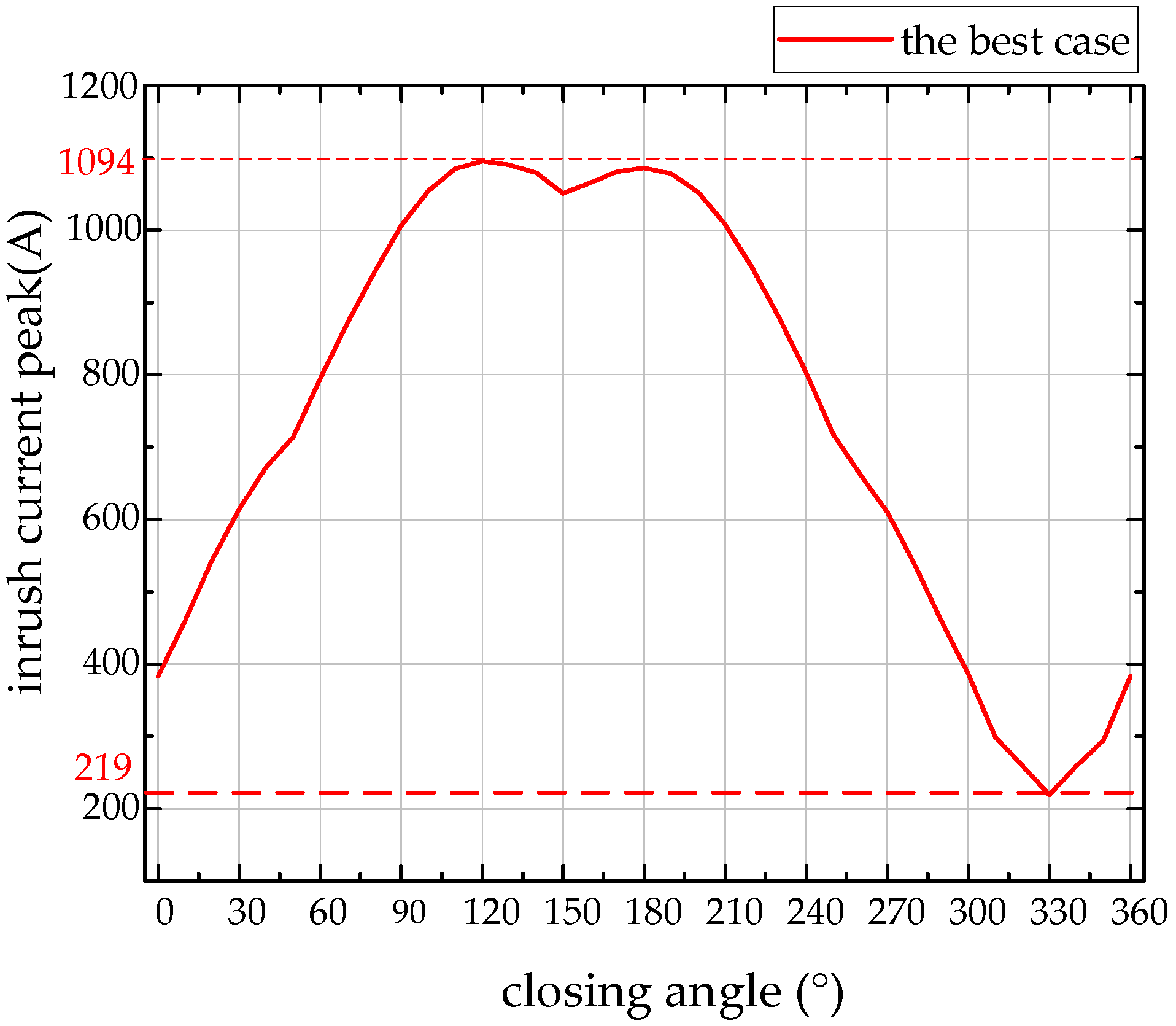
Figure 7 illustrates the simulated peak values of the magnetizing inrush current under varying closing phase angles with the optimal core residual flux distribution, where each data point is extracted as the maximum peak among the three phases under varying closing phase angles with the optimal core residual flux distribution. As illustrated in Figure 7, the parametric sweep was conducted across the full 0° to 360° range with a 1° step size. The sharp minimum observed at the 330° closing angle represents the optimal physical operating point where the prospective flux precisely aligns with the pre-magnetized residual flux, thereby completely minimizing the core saturation and transient inrush current. This result confirms that the magnetizing inrush current peaks of the remaining two phases are also strictly limited to an extremely low level, with all phase peaks well bounded below the maximum inrush current peak under conventional zero residual flux conditions.

4.3. Evaluation of Differential Energy Spectrum and Pre-Magnetization Circuit Design

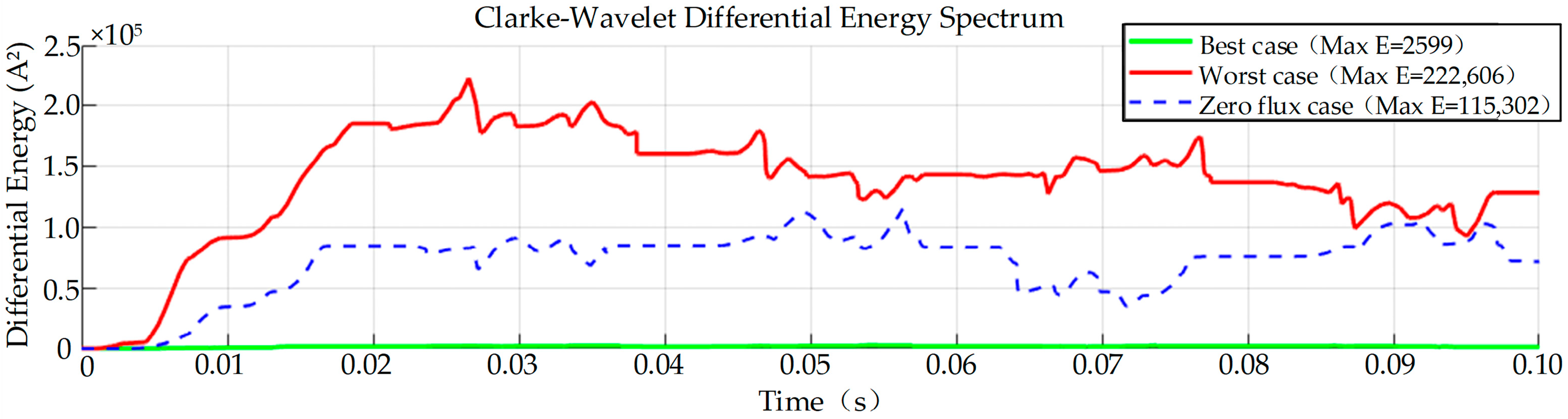
Traditional protection schemes based on second-harmonic restraint are highly susceptible to maloperation when magnetizing inrush currents are significantly attenuated. Using the three-phase transient current waveforms extracted in the preceding analysis, the quantitative assessment performance of the Clarke–Wavelet time-domain differential energy spectrum is validated. Comparative analysis of the energy characteristics under the three typical operating conditions is presented as illustrated in the Figure 8, and the key quantitative results of inrush current peak and differential energy are summarized in Table 2. The evaluated energy is calculated via integration over an initial 0.1 s simulation window. The analysis is conducted sequentially for the conventional zero residual flux working condition, the worst-case working condition with a random combination of core residual flux and closing phase angle, and finally the working condition with optimal core residual flux and closing phase angle matching.
As evidenced by the energy waveforms presented in the preceding figure, time-frequency domain analysis is conducted via differential energy spectrum extraction based on the Clarke–Wavelet. The analysis results first demonstrate that under the conventional zero residual flux condition, the differential energy exhibits a non-negligible sharp surge, with distinct transient characteristics driven by core saturation during transformer no-load energization. In sharp contrast, under the worst-case condition corresponding to a random combination of core residual flux and closing phase angle shown by the red line, the differential energy rises dramatically due to deep core saturation, presenting prominent fault-like characteristics. Finally, under the optimal matching condition of core residual flux and closing phase angle shown by the green line, the differential energy spectrum remains consistently near zero over the full analysis window. This confirms that accurate matching and retention of appropriate core residual flux, combined with targeted closing phase angle selection, can effectively eliminate high-frequency transient components and achieve a smooth energization transition in the transformer.
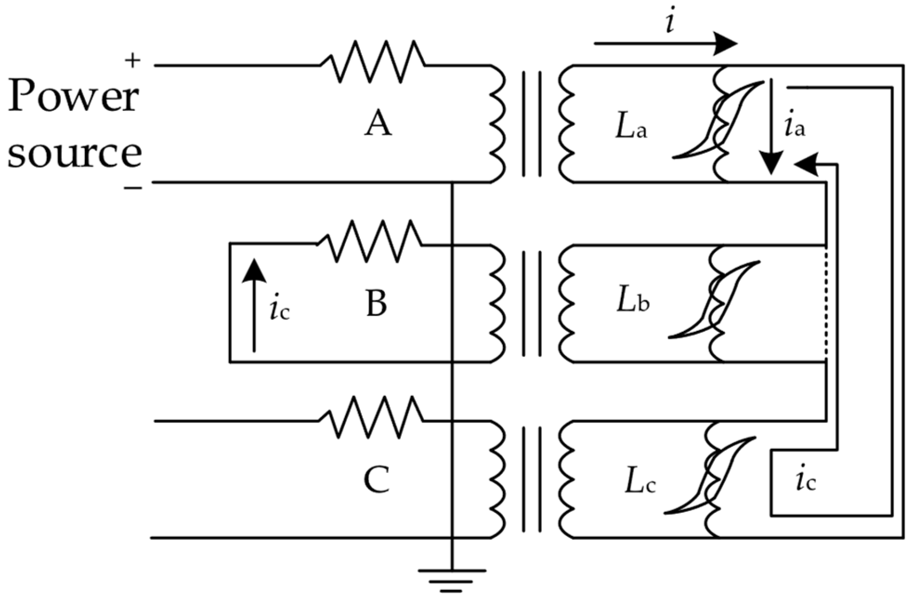
Based on the optimal matching law of core residual flux and closing phase angle obtained from the above simulation analysis, this paper proposes a quantitative, controllable pre-magnetization circuit topology for three-phase distribution transformers. This topology accurately injects quantitatively controllable preset core residual flux into the three-phase windings of the transformer, and completes the no-load closing of the transformer with the optimal closing phase angle verified in the previous analysis, so as to realize efficient suppression of the magnetizing inrush current from the physical source. The proposed pre-magnetization circuit is shown in Figure 9.
In this circuit configuration, Phase B of the transformer is short-circuited, Phase C is kept open-circuited, and an excitation voltage is applied to the winding of Phase A. Due to the short-circuit arrangement of Phase B, the magnetizing inductances of Phase A and Phase C present a parallel connection characteristic from the side of the input excitation terminal. Accordingly, magnetic fluxes with equal magnitude and opposite polarities are induced in Phase A and Phase C, namely positive residual flux in Phase A and negative residual flux in Phase C, while the flux in Phase B remains at zero consistently. Based on the hysteresis loop characteristics of the transformer core, the magnitude of the preset core residual flux can be accurately calculated via the excitation current, thus fully satisfying the prerequisite conditions for the coordinated closing strategy with optimal phase angle matching.

5. Conclusions

This paper conducts an in-depth investigation into the persistent issue of the magnetizing inrush current during the no-load energization of transformers, proposing a pre-magnetization strategy combined with Clarke–Wavelet energy spectrum evaluation. Based on theoretical analysis, full-traversal parametric sweep simulations, and multi-scale quantitative evaluations, the comprehensive results demonstrate that:
(1)
During the no-load energization of three-phase transformers, the magnetizing inrush current is governed not only by the switching angle but also profoundly by the initial core residual flux. The simulations pinpointed that the optimal suppression is achieved with a precise pre-magnetization distribution of −0.8 p.u. for Phase A, 0 p.u. for Phase B, and 0.8 p.u. for Phase C, coupled with a target closing phase angle of 330°.
(2)
The proposed collaborative control strategy strictly limits the peak inrush current to merely 219.1 A, which is approximately 1.5 times the rated current. This represents a significant reduction compared to the worst-case scenario (1048.8 A) and the conventional zero residual flux condition (635.8 A). Furthermore, the Clarke–Wavelet time-domain differential energy spectrum confirms this stability, with the transient energy dropping drastically from 115,302 A2 under full demagnetization to just 2599 A2 under optimal pre-magnetization.
(3)
Critical insight derived from this multi-scale assessment is that the conventional industry practice of full core demagnetization (achieving a zero residual flux state) is inherently sub-optimal. Instead, deliberately injecting and retaining an accurately matched residual flux profile fundamentally mitigates core saturation from its physical source, enabling a smooth, nearly impact-free transition to steady-state operation without severe harmonic distortion.
While this study establishes a comprehensive theoretical framework and provides high-fidelity simulation validations, it is essential to recognize the inherent limitations of the simulation approach. Transformer transients are inherently complex, and these simulations serve as an approximation of physical events. Specifically, extreme inrush currents induce intensive instantaneous heating, which may dynamically alter physical parameters such as winding resistance—a dynamic electro-thermal coupling not fully captured by the current model. Furthermore, practical implementations will inevitably face physical tolerances, such as variations in magnetic core materials. To address these unmodeled physical factors and the hardware complexity of precisely coordinating quantitative DC flux injection with microsecond-level point-on-wave synchronous switching, our future work will focus on developing a custom hardware prototype. This will enable comprehensive laboratory measurements and on-site field verification to capture real oscillograms, further validating the proposed pre-magnetization strategy under actual physical conditions.

Author Contributions

Conceptualization, C.L.; Software, S.H. and C.M.; Validation, C.L. and C.M.; Formal analysis, X.G.; Investigation, J.H.; Resources, J.H. and S.H.; Data curation, S.H. and S.G.; Writing—original draft, C.L.; Writing—review and editing, X.Z.; Visualization, J.H. and X.G.; Supervision, X.Z.; Project administration, C.L., J.H. and S.G.; Funding acquisition, C.L. and S.G. All authors have read and agreed to the published version of the manuscript.

Funding

This research was funded by the Science and Technology Project of State Grid Jiangsu Electric Power Co., Ltd., grant number [J2025155].

Data Availability Statement

The data presented in this study are available on request from the corresponding author. The data are not publicly available due to confidentiality reasons.

Conflicts of Interest

Author Chenlei Li was employed by the company Electric Power Company. Authors Junchi He, Shoujiang He, and Shaofan Gu were employed by the company State Grid Guanyun Power Supply Company. The remaining authors declare that the research was conducted in the absence of any commercial or financial relationships that could be construed as a potential conflict of interest.

References

  1. Fonseca, W.S.; Lima, D.S.; Lima, A.K.F.; Nunes, M.V.A.; Bezerra, U.H.; Soeiro, N.S. Analysis of structural behavior of transformer’s winding under inrush current conditions. IEEE Trans. Ind. Appl. 2018, 54, 2285–2294. [Google Scholar] [CrossRef]
  2. Zhu, L.H.; Li, J.J.; Yang, Q.X.; Zhu, J.G.; Koh, C.-S. An improved magnetostriction model for electrical steel sheet based on Jiles-Atherton model. IEEE Trans. Magn. 2020, 56, 7514604. [Google Scholar]
  3. Zheng, T.Y.; Hu, E.D.; Yang, H.; Zhao, R.; Kang, Y.C.; Wall, P.; Terzija, V. Fast, in situ demagnetization method for protection current transformers. IEEE Trans. Magn. 2016, 52, 8400904. [Google Scholar] [CrossRef]
  4. Zhang, S.; Yao, C.; Zhao, X.; Li, J.; Liu, X.; Yu, L.; Ma, J.; Dong, S. Improved flux-controlled VFCV strategy for eliminating and measuring the residual flux of three-phase transformers. IEEE Trans. Power Deliv. 2020, 35, 1237–1248. [Google Scholar] [CrossRef]
  5. Zhao, X.; Wu, H.; Yang, D.; Wei, J.; Li, Z.; Guo, Z.; Zhang, S. Residual magnetism elimination method for large power transformers based on energy storage oscillation. IEEE Trans. Power Deliv. 2025, 40, 2759–2768. [Google Scholar] [CrossRef]
  6. De Leon, F.; Farazmand, A.; Jazebi, S.; Deswal, D.; Levi, R. Elimination of residual flux in transformers by the application of an alternating polarity dc voltage source. IEEE Trans. Power Deliv. 2015, 30, 1727–1734. [Google Scholar] [CrossRef]
  7. Huo, C.; Yang, Y. A review of research progress on residual magnetism detection methods for power transformer cores. IEEE Sens. J. 2024, 24, 7636–7645. [Google Scholar] [CrossRef]
  8. Huo, C.; Wang, Y.; Liu, C.; Lei, G. Study on the residual flux density measurement method for power transformer cores based on magnetising inductance. IET Electr. Power Appl. 2021, 16, 224–235. [Google Scholar] [CrossRef]
  9. Huo, C.; Wang, Y.; Wu, S.; Yang, Y.; Zhao, Z. Residual flux density measurement method for transformer core considering relative differential permeability. IEEE Trans. Magn. 2021, 57, 8400204. [Google Scholar]
  10. Wei, C.; Li, X.; Yang, M.; Ma, Z.; Hou, H. Novel remanence determination for power transformers based on magnetizing inductance measurements. Energies 2019, 12, 4616. [Google Scholar] [CrossRef]
  11. Huo, C.; Wang, Y.; Zhao, Z.; Liu, C. Residual flux measurement of the single-phase transformer based on transient current method. IEEE Trans. Appl. Supercond. 2020, 30, 5500505. [Google Scholar] [CrossRef]
  12. Wu, S.; Ren, Y.; Wang, Y.; Huo, C.; Liu, C. Residual flux measurement of power transformer based on transient current difference. IEEE Trans. Magn. 2022, 58, 8400405. [Google Scholar] [CrossRef]
  13. Zheng, T.; Wang, Y. Fast and in situ remanent flux detection method for a protection current transformer based on the fluxgate theory. AIP Adv. 2021, 11, 15–34. [Google Scholar] [CrossRef]
  14. Cano-González, R.; Bachiller-Soler, A.; Rosendo-Macías, J.A.; Álvarez-Cordero, G. Controlled switching strategies for transformer inrush current reduction: A comparative study. Electr. Power Syst. Res. 2017, 14, 12–18. [Google Scholar] [CrossRef]
  15. Mitra, J.; Xu, X.; Benidris, M. Reduction of three-phase transformer inrush currents using controlled switching. IEEE Trans. Ind. Appl. 2020, 56, 890–897. [Google Scholar] [CrossRef]
  16. Ni, H.; Fang, S.; Lin, H. A simplified phase-controlled switching strategy for inrush current reduction. IEEE Trans. Power Deliv. 2021, 36, 215–222. [Google Scholar] [CrossRef]
  17. Han, P.; Tong, Q.; Wang, Y.; Chen, Z.; Yang, W.; Hu, D.; Wu, H.; Zhang, J. An inrush current suppression strategy for UHV converter transformer based on simulation of magnetic bias. IEEE Trans. Power Deliv. 2022, 37, 5179–5189. [Google Scholar] [CrossRef]
  18. Li, C.; Yang, Y.; Li, W.; Li, H. A soft-start-based method for active suppression of magnetizing inrush current in transformers. Electronics 2023, 12, 3114. [Google Scholar] [CrossRef]
  19. Chen, Z.; Li, H.; Dong, X.; He, Y.; Zhou, Q.; Zhang, Y.; Zhang, Y. Magnetizing inrush current elimination strategy based on a parallel type asynchronous closing hybrid transformer. IEEE Trans. Power Electron. 2023, 38, 931–943. [Google Scholar]
  20. Alassi, A.; Ahmed, K.H.; Egea-Alvarez, A.; Foote, C. Transformer inrush current mitigation techniques for grid-forming inverters dominated grids. IEEE Trans. Power Deliv. 2023, 38, 1610–1620. [Google Scholar] [CrossRef]
  21. Jain, A.; Saborío-Romano, O.; Sakamuri, J.N.; Cutululis, N.A. Virtual resistance control for sequential green-start of offshore wind power plants. IEEE Trans. Sustain. Energy 2022, 13, 1420–1429. [Google Scholar] [CrossRef]
  22. Islam, M.M.; Muttaqi, K.M.; Sutanto, D. A saturated amorphous alloy core-based inrush current limiter to eliminate inrush currents and restrain harmonics during transformer energization. IEEE Trans. Ind. Appl. 2021, 57, 6634–6645. [Google Scholar] [CrossRef]
  23. Aghazadeh, A.; Hajipour, E.; Li, K.; Azizi, S. Mitigating the inrush current of V/V transformers using railway conditioners. IEEE Access 2024, 12, 50885–50897. [Google Scholar] [CrossRef]
  24. Medeiros, R.P.; Costa, F.B.; Silva, M.K.; Muro, J.d.J.C.; Júnior, J.R.L.; Popov, M. A Clarke-wavelet-based time-domain power transformer differential protection. IEEE Trans. Power Deliv. 2022, 37, 317–328. [Google Scholar] [CrossRef]
  25. Oztekin, M.; Karagol, S.; Ozgonenel, O. Transformer differential protection with wavelet transform and difference function. Eng. Sci. Technol. Int. J. 2025, 70, 102144. [Google Scholar] [CrossRef]
  26. Moosavi, S.M.L.; Damchi, Y.; Assili, M. A new fast method for improvement of power transformer differential protection based on discrete energy separation algorithm. Int. J. Electr. Power Energy Syst. 2022, 136, 107759. [Google Scholar] [CrossRef]
  27. Mo, C.; Ji, T.; Zhang, L.; Wu, Q. Equivalent statistics based inrush identification method for differential protection of power transformer. Electr. Power Syst. Res. 2022, 203, 107664. [Google Scholar] [CrossRef]
  28. Key, S.; Son, G.W.; Nam, S.R. Deep learning-based algorithm for internal fault detection of power transformers during inrush current at distribution substations. Energies 2024, 17, 963. [Google Scholar] [CrossRef]
  29. Li, Z.; Xv, N.; Chen, X.; Zhang, Y.; He, A.; Jiao, Z. Blocking method with PSO-SVDD for differential protection of power transformer. Electr. Power Syst. Res. 2024, 237, 111016. [Google Scholar] [CrossRef]
  30. Yu, W.; Chen, J.; Dai, W.; Wu, T. A reinforced braking method to prevent maloperation of generator differential protection caused by sympathetic inrush. IEEE Trans. Power Deliv. 2025, 40, 3060–3072. [Google Scholar] [CrossRef]
  31. Harlow, J.H. (Ed.) Electric Power Transformer Engineering, 3rd ed.; CRC Press: Boca Raton, FL, USA, 2012; ISBN 978-1-4398-5636-9. [Google Scholar]
Figure 1. Schematic diagram of single-phase transformer no-load energization.
Energies 19 02070 g001
Figure 2. Flowchart of the inrush current mitigation assessment based on wavelet transform and energy features.
Energies 19 02070 g002
Figure 3. Simulation circuit diagram of transformer inrush current during energization.
Energies 19 02070 g003
Figure 4. Block diagram of magnetizing inrush current simulation workflow.
Energies 19 02070 g004
Figure 5. Time-domain simulation waveforms of the three-phase magnetizing inrush current under diverse configurations. (a) The zero residual flux condition following core demagnetization; (b) the worst-case scenario; (c) optimal suppression operating condition.
Energies 19 02070 g005
Figure 6. Spectral decomposition of the transient inrush currents up to the 5th harmonic. Comparing the DC offset and harmonic content across (a) the zero residual flux condition following core demagnetization; (b) the worst-case scenario; (c) optimal suppression operating condition.
Energies 19 02070 g006
Figure 7. Curves of three-phase maximum magnetizing inrush current peak under different closing phase angles with optimal core residual flux distribution.
Energies 19 02070 g007
Figure 8. Comparative time-frequency analysis using the Clarke–Wavelet differential operating energy spectrum.
Energies 19 02070 g008
Figure 9. Schematic diagram of the pre-magnetization system.
Energies 19 02070 g009
Table 1. Nameplate parameters of 10 kV/400 V three-phase transformer.
ParametersValue
Nominal capacity100 kVA
Voltage ratio400 V/10 kV
Rated current144 A/5.8 A
Nominal frequency50 Hz
Phase displacementDyn11
No-load loss0.1231 kW
Load loss1.1989 kW
Short-circuit impedance3.95%
No-load current0.15%
Table 2. Simulation results of inrush current and differential energization.
CaseInrush Current PeakEnergy
The zero residual flux condition following core
demagnetization
635.8 A115,302 A2
The worst-case scenario1048.8 A222,606 A2
Optimal suppression operating condition219.1 A2599 A2
Disclaimer/Publisher’s Note: The statements, opinions and data contained in all publications are solely those of the individual author(s) and contributor(s) and not of MDPI and/or the editor(s). MDPI and/or the editor(s) disclaim responsibility for any injury to people or property resulting from any ideas, methods, instructions or products referred to in the content.