Article

A Laboratory-Scale Moving-Bed Biomass Gasifier with Controlled Solid Displacement: Design and Performance Evaluation


Instituto de Investigaciones en Catálisis y Petroquímica “José Miguel Parera” INCAPE, UNL-CONICET, Colectora Ruta Nac. Nº 168 Km 0, Santa Fe 3000, Argentina
*
Author to whom correspondence should be addressed.
Energies 2026, 19(9), 2057; https://doi.org/10.3390/en19092057
Submission received: 18 March 2026 / Revised: 20 April 2026 / Accepted: 22 April 2026 / Published: 24 April 2026

Abstract

This study reports on the design, construction, and operation of a laboratory-scale biomass gasification reactor, together with the procedures used to define and evaluate key operational and performance variables, including piston velocity, nominal biomass residence time, airflow rate, gas yield, lower heating value, and gasification efficiency. The unit is a moving-bed reactor operating in co-current gas–solid mode and reproducing key features of downdraft-like gasification, allowing the identification of the four main reaction zones: drying, pyrolysis, oxidation, and reduction. The reactor exhibits simple operation and handling and, notably, enables controlled axial displacement of the biomass bed through the reaction zone, allowing the nominal solid residence time in the heated zone to be adjusted through piston motion. In addition, the gasification of Spartina argentinensis was investigated in order to evaluate the functionality of the system and to assess reactor performance under selected operating conditions. At operating temperatures of 800–850 °C and an equivalence ratio of 0.2, gas yields exceeded 60 wt%, gasification efficiencies were above 50%, and the product gas reached heating values close to 1000 kcal Nm−3, indicating a favorable fuel quality of the product gas. These results confirm the potential of the proposed reactor as a useful experimental platform for the investigation of biomass gasification under controlled laboratory conditions.

1. Introduction

Gasification is a thermochemical process involving the partial oxidation of organic materials, resulting primarily in gaseous products, commonly referred to as product gas, producer gas, or syngas, together with a solid residue (char) and minor amounts of condensable compounds known as tars [1]. Sub-stoichiometric quantities of an oxidizing agent are employed to prevent complete combustion of the feedstock. Compared with direct combustion, gasification offers higher overall efficiency and several additional advantages, including lower NOX and SOX emissions and lower oxygen demand. When biomass is used as the feedstock, gasification is regarded as one of the most flexible and promising technologies for clean energy production [2].
Biomass gasification can be performed on several reactor configurations, including fixed-bed, fluidized-bed, entrained-flow, and moving-bed systems, each associated with specific hydrodynamic, thermal, and conversion characteristics [3,4]. Among them, fixed-bed gasifiers, particularly downdraft units, are especially attractive for small- and medium-scale applications because of their relatively simple design and the comparatively low tar content of the product gas [3,5]. In contrast, with more complex operation, fluidized-bed and entrained-flow reactors generally offer improved mixing, heat transfer, and throughput [3,4]. In addition, the nature of the gasifying agent has a strong influence on process performance and product distribution. Air-blown gasification is operationally simple and economically attractive, but it generates a nitrogen-diluted gas with a moderate heating value, whereas steam- and oxygen-assisted gasification generally promote higher H2 contents and improved gas quality [4,5,6].
The product gas obtained can be standardized in terms of composition and quality and is generally easier to handle and has more applications than the original solid biomass. It can be used to fuel internal combustion engines, achieving electrical conversion efficiencies of up to 35–45%, as well as gas turbines. To meet these applications, the gas must exhibit a sufficiently high lower heating value (LHV, typically > 4 MJ Nm−3) and low concentrations of contaminant components (tars < 100 mg Nm−3, particulates < 50 mg Nm−3, metals < 0.025–0.1 ppm, and H2S < 20 ppm). The adaptation of existing engines, which are primarily designed for fossil fuels and often require modifications to the fuel injection system, remains a major challenge. In addition, syngas can be co-combusted with biogas derived from anaerobic digestion, providing a flexible option for combined renewable energy systems [7].
Beyond its role as an energy carrier for heat and power generation, syngas constitutes a key intermediate for the synthesis of liquid and gaseous biofuels and green chemicals. In this context, improving the efficiency and versatility of gasification processes is essential to enhance the overall valorization of biomass resources. An integrated approach that enables the effective use of all gasification products (fuels, chemicals, and thermal energy) is required to promote the large-scale exploitation of this technology within the global energy market [7].
Thermochemical conversion of lignocellulosic biomass residues through processes such as pyrolysis and gasification has attracted sustained scientific interest over the past few decades [7,8]. Promising results in this field were reported by this research group [9,10,11,12], with recent efforts focusing on the development of a biomass gasification system capable of reproducing key operational features of co-current downdraft-like gasification at the laboratory scale.
Both the biomass and the oxidizing agent are introduced at the top of the reactor in downdraft gasifiers and flow downward in co-current mode through successive reaction zones: drying, pyrolysis, oxidation, and reduction [13,14]. The product gas is withdrawn from the bottom of the reactor after passing through the high-temperature oxidation and reduction zones, which promote the thermal cracking and conversion of most tar compounds. As a result, downdraft gasifiers typically produce a cleaner gas, as compared to updraft configurations [15]. Nevertheless, replicating downdraft gasification at laboratory scale presents several limitations, including restricted flexibility in feedstock loading concerning particle size and humidity, low heat transfer coefficients, difficulties in start-up and temperature control, and, critically, limited control over solid residence time [7].
Besides the well-recognized operational advantages, the extrapolation of laboratory-scale gasification results to industrial practice remains fundamentally problematic. Most laboratory reactors operate under fluid dynamic and thermal conditions that differ substantially from those of industrial downdraft systems, particularly with respect to flow regime, solid–gas contact pattern, and particle residence time distribution. As a result, the residence time of biomass particles within the reactive zones cannot be reliably determined or controlled, thereby compromising the robustness of kinetic interpretations and limiting the predictive value of experimental data for scale-up purposes [1,15]. This mismatch between laboratory configurations and commercial operation constitutes a critical barrier to the development of physically sound and industrially relevant gasification models.
In this context, the development of laboratory-scale reactors capable of reproducing key features of downdraft gasification under controlled experimental conditions is necessary. Downdraft gasifiers are among the most extensively implemented industrial configurations for biomass gasification and are particularly suited for decentralized and small-scale energy applications [16,17]. Their characteristic features (high carbon conversion efficiency, extended solid residence times, low superficial gas velocities, limited ash and particulate entrainment, and comparatively low tar production) define a reaction environment that is both technologically mature and industrially relevant. Consequently, experimental platforms that accurately emulate these conditions are essential to generate reproducible data, enable rigorous kinetic analyses, and establish reliable scale-up criteria [1,7,16].
Recent reviews have emphasized that current biomass gasification research is increasingly focused on reactor optimization, syngas quality improvement, tar mitigation, and advanced modeling approaches [3,5]. However, despite these advances, laboratory-scale systems that simultaneously provide simple operation, downdraft-like co-current behavior, and mechanically controlled solid displacement remain scarce. In particular, one persistent limitation of most laboratory-scale reactors is the difficulty of following the progression of the solid phase through the reactive zone in a physically explicit way. This gap is especially relevant for studies aimed at evaluating reactor operability, process reproducibility, and the effect of nominal residence time under controlled laboratory conditions.
The aim of the present work was to design, construct, and evaluate a laboratory-scale moving-bed biomass gasifier capable of reproducing key features of co-current downdraft-like gasification while enabling mechanically controlled displacement of the biomass bed through the heated reaction zone.
The gasification of Spartina argentinensis was used as a preliminary case study to assess reactor operation under selected conditions using air as the gasifying agent. Spartina argentinensis is a native perennial C4 grass from northeastern Argentina with recognized potential as lignocellulosic biomass for bioenergy applications. In Santa Fe Province, grasslands dominated by this species in the Bajos Submeridionales region extend over more than two million hectares, indicating its regional relevance as a potential feedstock for thermochemical conversion. Moreover, previous studies by Jozami and co-workers have explored its use for second-generation bioethanol production, bioenergy assessment, and pellet gasification, supporting its selection in the present work [18,19].

2. Materials and Methods

2.1. Description of the Laboratory Gasifier

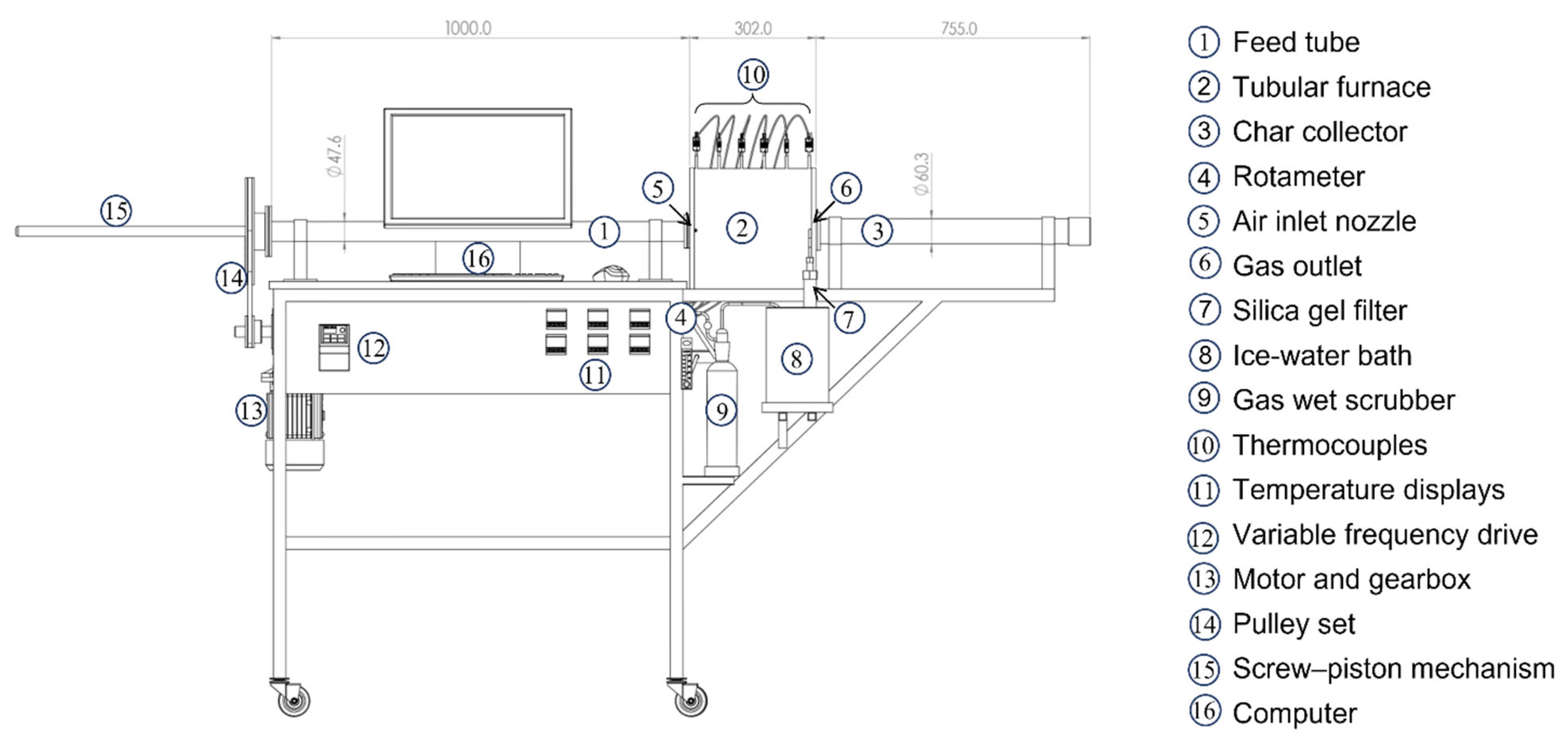
The designed gasifier is a laboratory-scale moving-bed unit. A schematic diagram of the complete system, including its main components and dimensions, is shown in Figure 1. A rendered image of the system is included in the Supplementary Material (Figure S1).
The system comprises a horizontal tubular reactor equipped with a feeding tube that houses a biomass-containing basket. The biomass loading capacity of the reactor is not fixed but depends on the apparent density, particle morphology, and packing characteristics of the feedstock. Biomass loads ranged from approximately 55 g for low-density materials such as rice husk to about 270 g for dense pelletized feedstocks such as Spartina argentinensis. After passing through the reaction zone, the basket reaches a dedicated char-collection chamber. The reaction zone is heated by a tubular electric furnace with a resistance heater capable of reaching temperatures of up to approximately 900 °C.
A nozzle allows the controlled introduction of air at the inlet of the reactor, while a second nozzle at the outlet enables the continuous removal of the product gases. Under these conditions, air flows co-currently with the biomass feed, thus reproducing the basic co-current operating principle of downdraft gasification.
The feeding section consists of a polished steel tube with an internal diameter of 38.1 mm and a total length of 1000 mm, into which the basket containing the biomass is inserted. The basket is displaced through the reactor by the action of a piston during operation. The basket is made from stainless steel tubing with an internal diameter of 30.1 mm and a length of 690 mm, which is perforated to allow the contact of air with the biomass bed. Its movement from the feeding zone to the char-collection zone is driven by a piston whose velocity is controlled by a variable frequency drive (Delta Electronics, Inc., Taipei, Taiwan, 0.4 kW, 0.5 HP, single-phase, 220 VAC).
The piston is a threaded rod driven by a 0.18 kW electric motor coupled to a gearbox with a 1:100 reduction ratio, complemented by an additional pulley system providing a further 5:1 reduction. This configuration allows the controlled adjustment of the basket displacement velocity and, consequently, of the nominal residence time of the biomass bed within the heated reaction zone.
The reaction zone itself is a stainless steel tube with an outer diameter of 48.3 mm and a length of 302 mm. An electric resistance heater is wound around this tube, which is subsequently insulated with ceramic fiber and enclosed within an external stainless steel casing. Downstream of the reaction zone, the char-collection section consists of a stainless steel pipe with an outer diameter of 60.33 mm and a length of 755 mm.
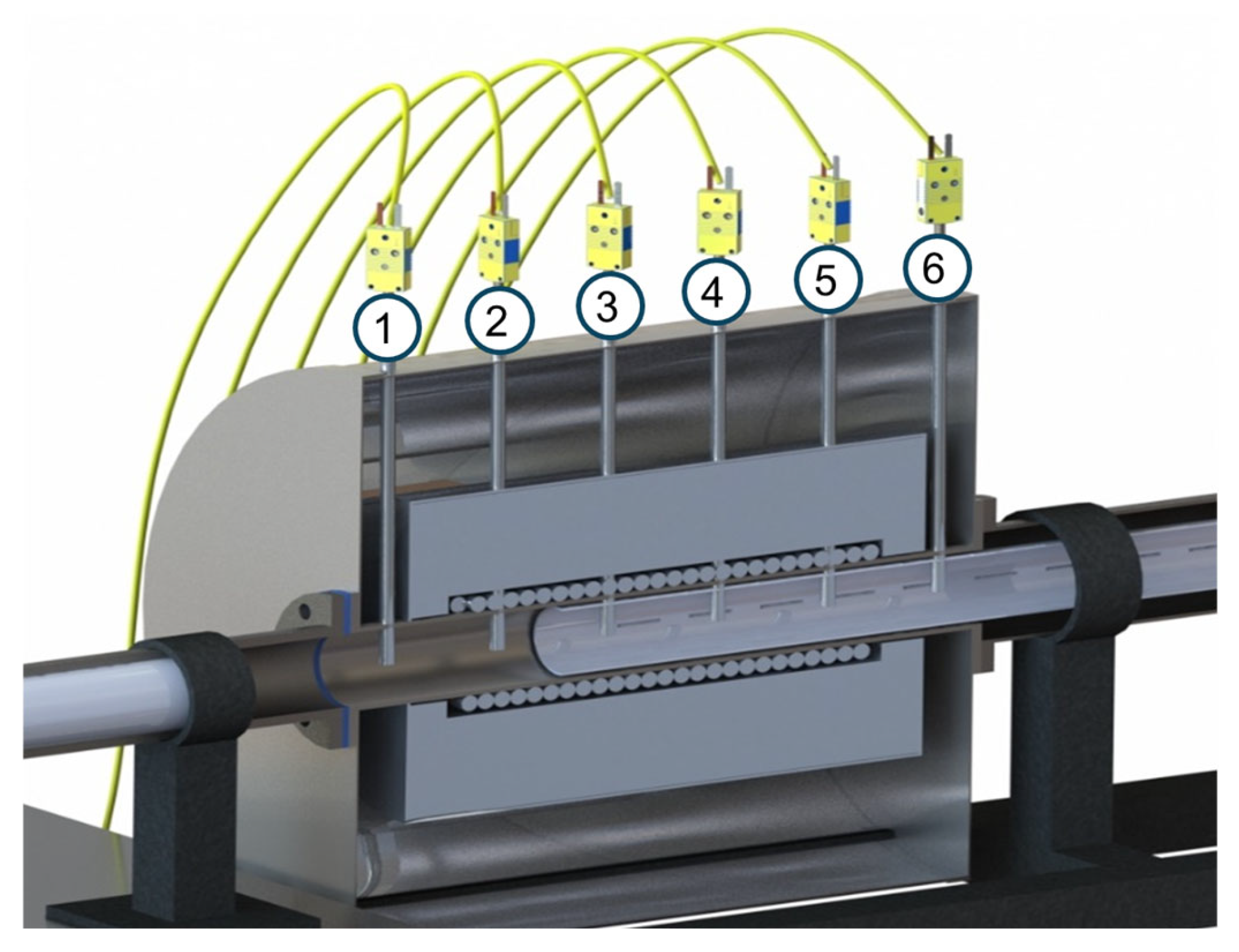
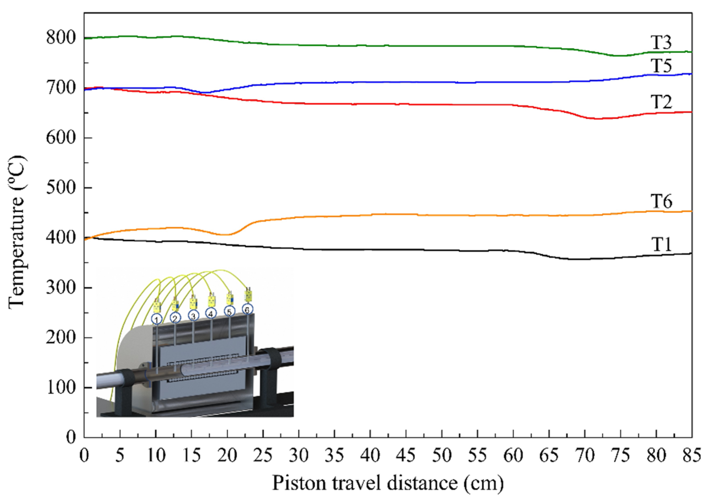
Temperature monitoring along the reactor is achieved using six Type K thermocouples. One thermocouple is positioned at the air inlet (T1), followed by four thermocouples evenly distributed along the furnace length in the region where the heating resistance is installed and a final thermocouple located at the gas outlet (T6). A rendered cross-sectional view of the reaction zone, showing the heating coil, basket trajectory, thermocouple locations, and thermal insulation, is shown in Figure 2.
The thermocouples are connected to individual temperature displays (NOVUS N1500, NOVUS Automation, Canoas, Brazil), and data are recorded as a function of time using a USB-i485 converter (NOVUS Automation, Canoas, Brazil). Thermocouple number 4 (T4), located at the center of the furnace, is connected to the furnace temperature controller (NOVUS N480D, NOVUS Automation, Canoas, Brazil) and used for temperature control during operation.
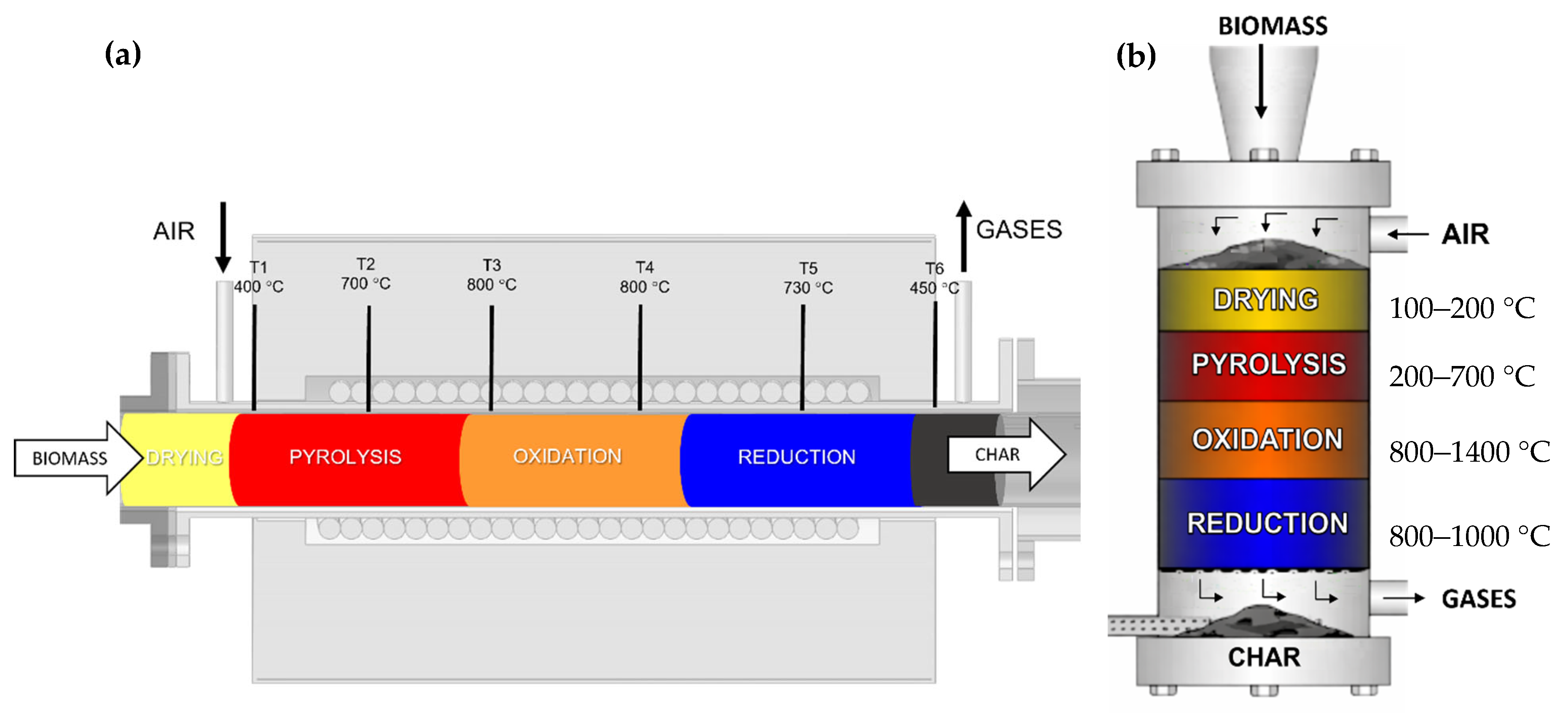
The four reaction zones expected to develop along the reactor length (drying, pyrolysis, oxidation, and reduction) are schematically represented in Figure 3. Their existence and spatial distribution can be determined from the axial temperature profile in the reactor, together with the characteristic physicochemical transformations occurring on reactants and products during biomass gasification. This sequence of thermal and reaction stages is typical of downdraft gasification systems [13,14].
The airflow rate to the reactor is manually adjusted and monitored using a BROOKS rotameter (model 2520A, Brooks Instrument, Hatfield, PA, USA), suitable for airflow rates in the range of 0.1–1 L min−1. The actual airflow selected for each experiment depended on the equivalence ratio, biomass type, and biomass displacement velocity. In the experiments reported in this work, the airflow rate was 0.320 L min−1 in the rice husk gasification test used for gas sampling analysis and 0.940, 0.980, and 0.980 L min−1 in the Spartina argentinensis gasification experiments carried out at 700, 800, and 850 °C, respectively.
Product gases exiting the reactor pass through a gas cleaning train consisting of a silica gel cartridge externally cooled using an ice–water bath, where condensable tars are retained, followed by a wet gas scrubber in which residual liquids are collected.
After cleaning, gases are vented to the atmosphere. Gas samples are collected using Tedlar gas sampling bags for subsequent chromatographic analysis. Gas flow rate measurements and gas sampling were performed using a gas collector consisting of a glass column with a diameter of 28 mm and a length of 1000 mm, initially filled with water.
The gasifier can be operated continuously for periods ranging from 1.5 to 7 h, depending on the selected biomass displacement speed. A key advantage of this design is the ability to control the axial displacement of the biomass bed within the reactor and, from that displacement, to estimate and adjust its nominal residence time in the heated reaction zone. This feature is difficult to achieve in conventional laboratory-scale downdraft gasifiers, where biomass progression is generally governed by gravity and bed packing is not directly controllable [15,20].

2.2. Determination of Operational and Performance Variables

2.2.1. Airflow Rate

The airflow rate supplied to the gasifier is one of the most critical operating parameters, since excessively high values may lead to combustion, whereas very low values may result in incomplete gasification or predominantly pyrolytic behavior [1,15]. For this reason, the equivalence ratio (ER) is defined according to Equation (1):
E R = A m o u n t   o f   a i r   s u p p l i e d S t o i c h i o m e t r i c   a m o u n t   o f   a i r
The stoichiometric air requirement was calculated from the elemental composition of the biomass. In this calculation, carbon and hydrogen were assumed to be fully oxidized to CO2 and H2O, respectively, while the oxygen contained in the biomass was included in the oxygen balance. Fuel-bound nitrogen, rather than atmospheric nitrogen, was considered in the calculation.
The airflow rate must be calculated for each experimental run, as it depends not only on the selected ER value but also on the type of biomass and its displacement velocity through the reactor. The airflow rate is determined using Equations (2) and (3):
Q a i r = E R   ×   Q a i r , s t o i c h
Q a i r , s t o i c h = A s t o i c h × ρ b i o m a s s × Q b i o m a s s × 1000     60
where Qair is the airflow rate (L min−1), Qair, stoich is the stoichiometric airflow rate (L min−1), Astoich is the stoichiometric air requirement (m3 kg−1), ρbiomass is the apparent density of the biomass (biomass mass per basket volume) (kg m−3), and Qbiomass is the volumetric flow rate of the biomass along the reaction zone (m3 h−1), which depends on the biomass displacement velocity through the reactor.

2.2.2. Product Yields

The mass of tar and condensed water (mtar) was determined from the difference in weight of the silica gel cartridge before and after each experiment, while the mass of solid products (mchar) was determined gravimetrically. The mass of biomass fed to the reactor (mbiomass) was recorded for each run. Within the exploratory scope of this study, the gas product yield was estimated by difference from the measured biomass, char, and condensed fractions. Therefore, the reported gas yield should be regarded as an approximate value derived from the overall mass balance, rather than the result of a direct gas mass measurement. As the gaseous fraction was estimated by difference, the reported gas yield is affected by the cumulative uncertainty associated with the measured solid and condensed fractions and should therefore be interpreted as an approximate performance indicator within the exploratory scope of the present study.

2.2.3. Heating Value of the Product Gas

The lower heating value (LHV) is a key parameter for assessing the quality and energetic potential of the product gas. This value was calculated using Equation (4) based on the volumetric composition of the gas and the individual LHVs of its combustible components:
                L H V g a s = L H V i   ×   x i
where x i is the volumetric fraction of each component (H2, CO, and CH4) in the product gas, and L H V i is its lower heating value expressed in MJ m−3. These values were obtained from Perry’s Chemical Engineers’ Handbook [21].

2.2.4. Gasification Efficiency

Cold gas efficiency (CGE) is an important performance indicator for the design and evaluation of gasification systems, as it reflects the fraction of the chemical energy content of the biomass that is transferred to the product gas. CGE is defined as the relationship between the energy content of the product gas and that of the biomass feedstock [22,23]. In this study, CGE was calculated according to Equation (5):
C G E = Q g a s   L H V g a s Q b i o m a s s   × L H V b i o m a s s × 100  
where Q g a s is the volumetric flow rate of the product gas (L h−1), L H V g a s is its lower heating value (kcal L−1), Q b i o m a s s is the mass flow rate of biomass fed to the reactor (kg h−1), and L H V b i o m a s s is the lower heating value of the biomass (kcal kg−1).

2.3. Gas Composition

The composition of the product gas was determined by gas chromatography using an Agilent 6890N gas chromatograph equipped with an on-column injection system, a GS-Carbon PLOT capillary column (30 m length, 530 μm internal diameter, and 3 μm film thickness), and a thermal conductivity detector (TCD). A cryogenic CO2 cooling system was employed to achieve initial column temperatures below ambient, enabling the adequate separation of permanent gas components.
Identification and quantification of the main gas species were performed using a certified calibration gas mixture supplied by Air Products Indura Argentina, containing H2 (17.82 vol%), CO (18.25 vol%), CH4 (4.89 vol%), and CO2 (13.83 vol%), with N2 as the balance gas (45.21 vol%). Calibration curves were constructed for each component, allowing the determination of specific chromatographic response factors used for the quantitative analysis of the product gas composition.

2.4. Biomass Characterization

The biomass used in the validation experiments was Spartina argentinensis, selected because of its regional abundance in northeastern Argentina and its previously reported potential as a lignocellulosic feedstock for bioenergy applications [18,19]. This biomass was characterized following standard procedures. Moisture content, volatile matter, and ash content were determined according to ASTM D3173 [24], ASTM D3175 [25], and ASTM D3174 [26] standards, respectively, while fixed carbon content was calculated by difference. Elemental composition (C, H, and N) was determined using a CHN628 Series elemental analyzer (LECO Corporation, St. Joseph, MI, USA), in accordance with ISO 16948 [27].
The higher heating value (HHV) of the biomass was estimated using the Dulong correlation [28], based on the elemental composition, according to Equation (6):
HHV (MJ kg−1) = 0.3383 C + 1.443 (H-O/8)
where C, H, and O are the mass percentages of carbon, hydrogen, and oxygen, respectively, on a dry basis.
The lignocellulosic composition of the biomass was determined using acid detergent lignin (ADL; PROMEFA V2 protocol with an ANKOM analyzer, ANKOM Technology, Macedon, NY, USA), sequential acid detergent fiber (ADF S, ISO 13906:2008 [29]), and amylase-treated neutral detergent fiber (aNDF, ISO 16472:2006 [30]) analyses. In this framework, ADL represents the lignin content, ADF S corresponds to the combined lignin and cellulose content, and aNDF represents the sum of lignin, cellulose, and hemicellulose [31].

3. Results and Discussion

3.1. Validation of the Gasification System

3.1.1. Piston Velocity

The feedstock biomass is loaded into a perforated basket, which is displaced along the reactor by a piston, as described in Section 2.1. During operation, the basket moves successively from the feeding section to the heated reaction zone and finally to the char-collection chamber. The piston motion is generated by an electric motor coupled to a screw-driven mechanism; therefore, the piston displacement rate depends on the motor frequency set in the variable frequency drive.
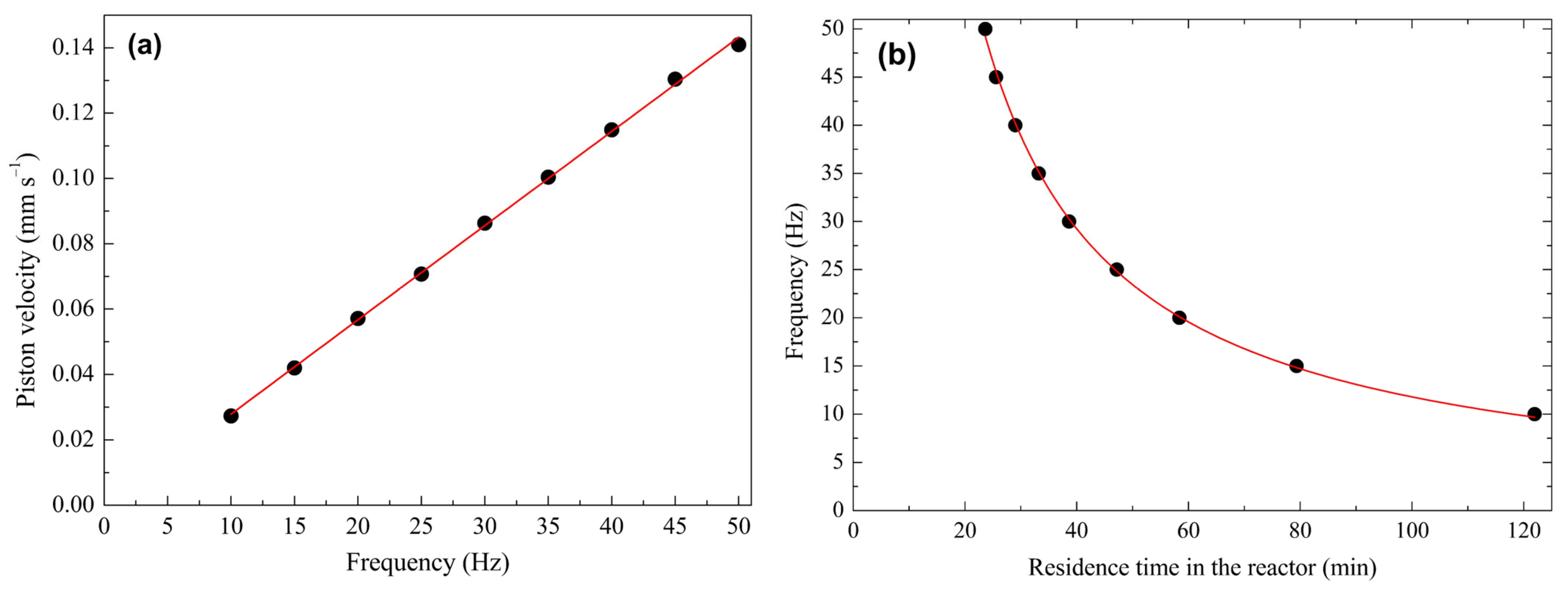
In order to determine this relationship, the time required for the piston to travel a fixed distance of 10 mm was measured at different motor frequencies in the range 10–50 Hz. Six independent measurements were performed at each frequency, and the average travel time was used to calculate the corresponding piston velocity. Figure 4a shows the resulting relationship between motor frequency and piston velocity.
Once the piston velocity was determined, the nominal residence time of the biomass bed inside the heated reaction zone was estimated from the time required for the basket to travel across the 200 mm section of the reactor occupied by the electrical resistance coil. Accordingly, the residence time was calculated as the relationship between the heated-zone length and the piston velocity. In this way, the experimentally measured piston displacement was directly translated into the nominal time during which the confined biomass bed remained inside the heated reaction zone. The relationship between motor frequency and nominal biomass residence time is shown in Figure 4b.
Based on these experimental data, empirical correlations were derived to facilitate the selection of operating conditions. In particular, the correlation shown in Figure 4 was used to select the motor frequency required to achieve the desired nominal residence time of the biomass bed in each experiment. In the experiments reported in this study, nominal residence times of 70 and 80 min were employed. Equation (8) was further used to calculate the piston velocity as a function of motor frequency. This velocity was subsequently used to determine the biomass volumetric flow rate through the reactor and, from that value, the corresponding airflow rate required for each experiment.
F r e q u e n c y = ( 1131.3 ) × ( R e s i d e n c e   t i m e ) 0.991
P i s t o n   v e l o c i t y = 0.0029 × F r e q u e n c y

3.1.2. Gas Sampling

A gasification experiment using rice husk was carried out to determine an appropriate piston position to perform gas sampling. Rice husk was selected for this preliminary test as a convenient biomass for system validation, as the purpose of the experiment was not to compare feedstocks but to define an operational gas-sampling criterion as a function of piston displacement. The evolution of product gas composition was monitored as a function of piston displacement in this test, which directly reflects biomass progression through the reactor. The composition of the rice husk used in this experiment has been reported elsewhere [12]. The operating conditions were 800 °C, an equivalence ratio of 0.4, and a biomass residence time of 70 min, with a total experimental duration of 5.5 h.
Figure 5 shows the temperature profiles measured by the reactor thermocouples as a function of biomass progression along the reactor. Thermocouple T4 (Figure 2) is not included, as it was used for furnace temperature control. As the biomass progressed through the reactor, the temperature signals evolved sequentially along the thermocouples located in the heated section. This behavior is consistent with the progressive development of the drying, pyrolysis, oxidation, and reduction stages along the reactor axis. In particular, the thermal response observed in the central region of the furnace and the increase in outlet gas temperature indicate that the biomass reached the most active reaction zone.
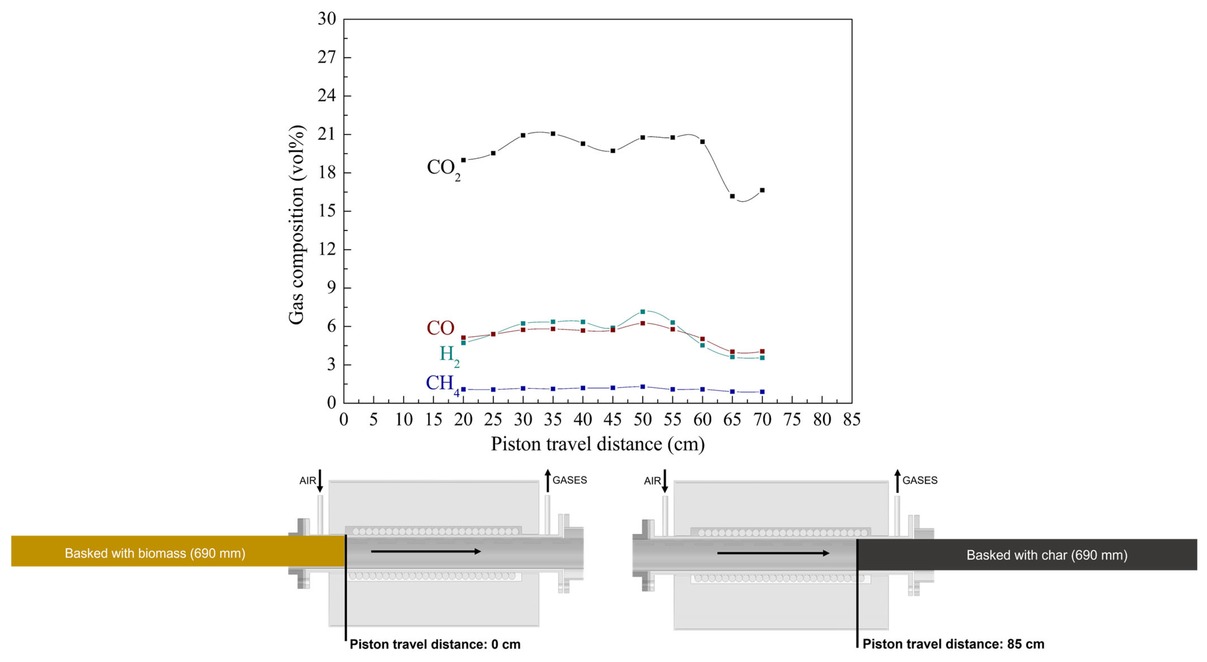
Piston displacement was continuously recorded during the experiment, and gas samples were collected every 5 cm of piston travel. The resulting gas compositions are shown in Figure 6. As the product gas was diluted by the nitrogen introduced with the air stream, the concentrations of the main gaseous species of interest (H2, CO, CH4, and CO2) are only reported, expressed as volume percentages. The increase in the concentrations of combustible gases observed in Figure 6 is consistent with the thermal evolution shown in Figure 5, particularly once the biomass reached the most active region of the heated section.
As these studies provide a useful context shown in Figure 6, the concentrations of H2, CO, and CH4 increased with piston displacement, reaching maximum values in the range of 50–55 cm from the initial piston position, and then gradually decreased. This decrease may be attributed to the progressive consumption of the most reactive fraction of the biomass after it crossed the most active gasification region, leading to a lower extent of gas-generation reactions and, consequently, to reduced concentrations of combustible species in the outlet gas. The piston reached the position between 50 and 55 cm from its initial position at approximately 190 min from the start of the experiment, considering a displacement velocity of about 0.045 mm s−1.
For the purposes of this work, the region between 50 and 55 cm was operationally defined as a quasi-stable sampling zone, as it combined the highest concentrations of the main combustible gases with only minor variations between consecutive samples. This criterion was used as a practical reference for gas sampling in subsequent experiments. Since the progress of the solid through the reactor is governed by piston movement, the sampling criterion was expressed in terms of piston displacement rather than elapsed reaction time.
This sampling criterion was established from the rice husk experiment used for system validation. It provided a consistent practical basis for selecting the sampling point in the experiments carried out in this study, but its general applicability to other biomasses and operating conditions was not independently verified and should therefore be regarded as an operational approximation.

3.2. Gasification of Spartina argentinensis

As part of the preliminary validation and performance assessment of the system, the gasification of Spartina argentinensis was investigated. This perennial grass, considered invasive in the islands of the Paraná River Delta, Argentina [19], has been identified as a lignocellulosic biomass with potential for biorefinery applications. The biomass was supplied by the Instituto de Investigaciones en Ciencias Agrarias de Rosario (IICAR), Facultad de Ciencias Agrarias, Universidad Nacional de Rosario (FCA-UNR).
The biomass was fed in pelletized form, 6 mm in diameter, with pellet lengths ranging from 8 to 20 mm and an apparent density of 165 kg m−3. The biomass was characterized in terms of its physicochemical properties, as summarized in Table 1. These data show that Spartina argentinensis presents a physicochemical profile consistent with its feasible use as a feedstock for thermochemical conversion. Its composition suggests a significant potential for the formation of gaseous and condensable products during heating, while its fuel properties support its energetic relevance. Moreover, the predominance of structural carbohydrates in its lignocellulosic fraction is consistent with the expected reactivity of a perennial herbaceous biomass under gasification conditions. Altogether, these features provide a suitable basis for assessing reactor performance with this feedstock.
Gasification experiments were conducted at an equivalence ratio of 0.2, with a nominal biomass residence time of 80 min in the heated reaction zone and reaction temperatures of 700, 800, and 850 °C. Approximately 250 g of biomass was fed to the reactor in each experiment. The temperature records from the reactor thermocouples as a function of biomass progression along the reactor in the experiments conducted with Spartina argentinensis are shown in Figure S2 of the Supplementary Material. These profiles provide additional support for the zonal interpretation of reactor behavior discussed above. In all cases, distinct temperature levels could be identified along the reactor axis, consistent with the sequential occurrence of drying, pyrolysis, oxidation, and reduction zones. As expected, the temperatures in these zones varied with the selected furnace temperature setpoint, with the highest values being observed in the central reaction region associated with oxidation.
When gasification was performed at 700 °C, the average temperatures were approximately 320, 580, 700, and 610 °C in the drying, pyrolysis, oxidation, and reduction zones, respectively. When the process was conducted at 800 °C, these values increased to approximately 370, 660, 800, and 710 °C. Finally, at a gasification temperature of 850 °C, the corresponding temperatures were approximately 390, 700, 850, and 750 °C. In addition, in all cases, the temperature measured at the gas outlet (thermocouple T6) increased once the biomass progressed through the heated section, reaching values of 384, 471, and 502 °C for furnace temperatures of 700, 800, and 850 °C, respectively. These results are consistent with the progressive development of the gasification stages along the reactor and reinforce the interpretation of downdraft-like operation under the conditions studied.
The yields of the different product streams obtained under these conditions are shown in Table 2. Gas yields were consistently high, exceeding 50 wt% under all operating conditions. This is desirable, as the main objective of gasification is the production of fuel gas. The highest gas yield was obtained at 800 °C, while char yields decreased with increasing temperature. This behavior suggests that, within the temperature range studied, 800 °C provided the most favorable balance between primary devolatilization and secondary gas-forming reactions. Compared with 700 °C, the higher temperature is expected to intensify tar cracking and heterogeneous conversion reactions, thereby promoting gas formation and reducing the amount of solid products. In all cases, tar formation remained low, indicating effective conversion of condensable species within the high-temperature zones of the reactor. This behavior is consistent with the general trend reported for downdraft gasifiers, in which volatile products pass through high-temperature oxidation and reduction zones that favor secondary cracking and reforming reactions [13,15,17]. Tar production is most commonly reported in the literature relative to the amount of producer gas, usually in units of g Nm−3. However, Ibrahim et al. [32] expressed tar yield on a mass basis, i.e., as the mass of tar per unit mass of biomass, after converting data originally reported in g Nm−3. Using this approach, they reported tar yields in the range of approximately 0.08 to 1.7 wt% for ER values between about 0.20 and 0.40 in experimental downdraft gasifiers at laboratory and pilot scales, using different feedstocks such as sewage sludge, pine wood, and corn straw, among others.
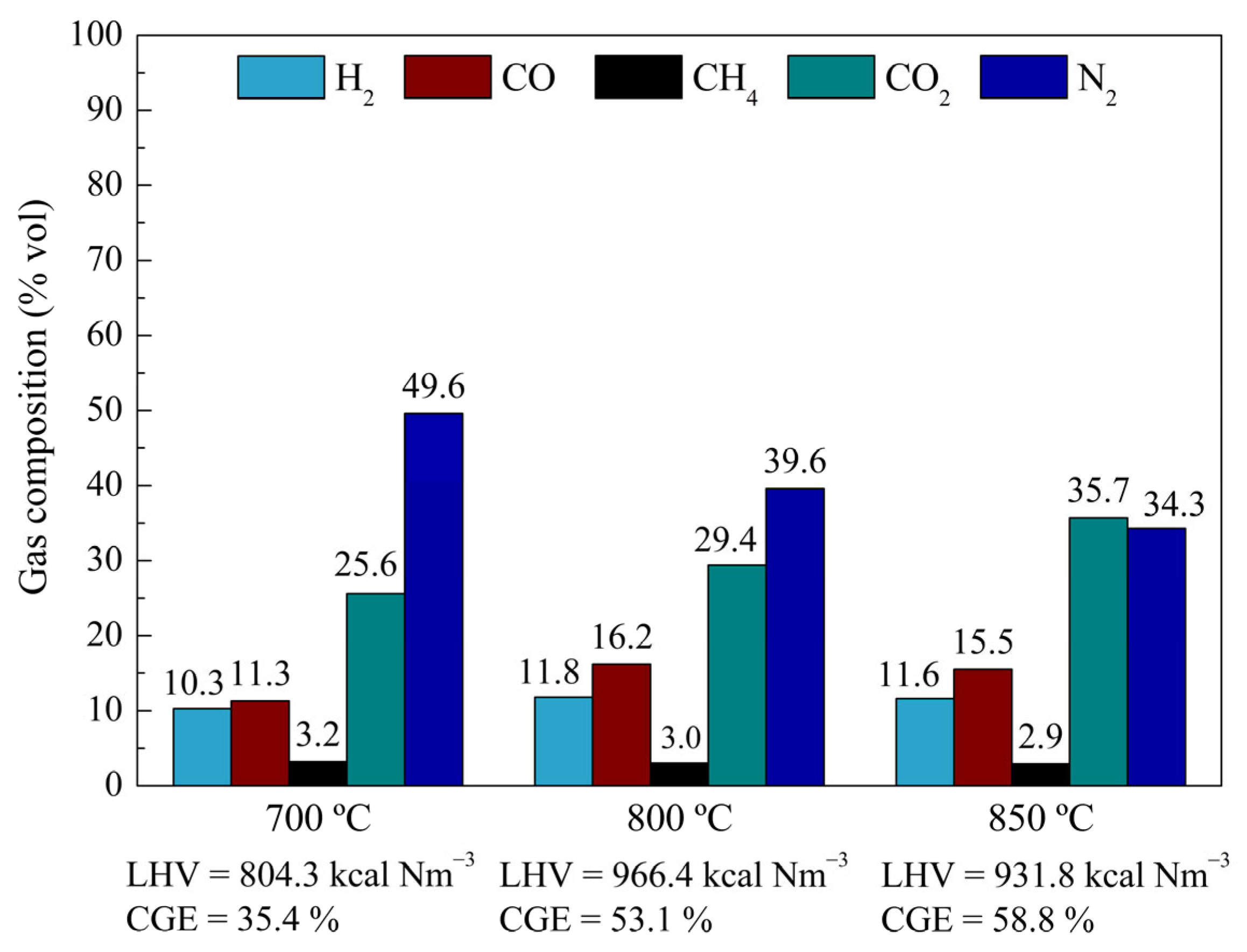
Figure 7 shows the composition of the product gases obtained under the different operating conditions, together with the corresponding low heating values and cold gas efficiencies. Cold gas efficiencies above 50% were obtained at 800 and 850 °C. The trends shown in Figure 7 indicate that the operating temperature influenced not only gas yield but also the energetic quality of the product gas. The more favorable results observed at 800–850 °C are consistent with increased gas formation and more effective conversion of condensable intermediates under those conditions. From a physicochemical standpoint, the effect of temperature on gas composition can be associated with the greater extent of secondary cracking and reforming reactions at higher temperatures, which promote the formation of combustible gases such as H2 and CO from condensable intermediates and residual char [33,34]. The product gas reached lower heating values close to 1000 kcal Nm−3 at these temperatures, which fall within the range commonly reported for air-blown downdraft gasifiers, typically around 4–6 MJ Nm−3, depending on feedstock and operating conditions [13,33], and thus indicate a favorable fuel quality. These results demonstrate that the gasification of Spartina argentinensis in the proposed reactor is feasible under the conditions evaluated. In addition, the results show that the selected operating temperature affected gas yield, gasification efficiency, and gas heating value. Within the limited experimental set considered here, the most favorable performance was observed at 800–850 °C. These findings should be interpreted within the exploratory scope of the present study, whose purpose was to demonstrate reactor operability and its response to changes in operating temperature, rather than to provide a complete statistical validation of reactor performance.

3.3. Distinctive Features and Comparative Assessment of the Proposed Gasifier

The performance observed in the present study is consistent with values reported for downdraft gasification systems operating with different lignocellulosic feedstocks. For example, Nisamaneenate et al. [34] reported lower heating values in the range of 3.43–3.92 MJ Nm−3 and cold gas efficiencies between approximately 40 and 66% during peanut shell gasification in a modular fixed-bed downdraft gasifier. Under the optimum condition identified in their study, obtained at an airflow rate of 3.06 m3 h−1, the product gas reached a lower heating value of 3.92 MJ Nm−3 and a cold gas efficiency of 60.65%, while oxidation-zone temperatures were in the range of 700–800 °C. Likewise, Pérez et al. [35], working with laboratory-scale fixed-bed downdraft reactors fed with pine bark and sewage sludge, reported lower heating values reaching 2965.6 kJ Nm−3 under optimum gasification conditions corresponding to an air superficial velocity of 0.06 m s−1 and operating temperatures in the range of 877–1000 °C. Besides the fact that direct comparison is limited by differences in feedstock properties, reactor design, and operating conditions, these studies provide a useful context for the favorable performance obtained in the present work.
From a comparative standpoint, the main contribution of the proposed reactor is not simply the reproduction of downdraft-like co-current operation at a laboratory scale but the integration of that behavior with mechanically controlled displacement of the confined biomass bed. In contrast to previously reported laboratory-scale systems, in which biomass progression is generally governed by gravity, the present configuration allows the solid phase to be advanced through the heated zone in a controlled and physically explicit manner through piston motion. This makes it possible to define and adjust the nominal residence time of the biomass bed under well-controlled laboratory conditions, which constitutes a relevant methodological advantage for gasification studies.
Under the exploratory scope of this study, the specific design of this moving-bed reactor is particularly advantageous for the evaluation of biomass feedstocks. Once loaded into the basket, the biomass forms a confined packed bed that is displaced as a whole by the action of the piston. The axial rearrangement of the solid phase within the reactor is expected to be limited under these conditions, as compared to systems in which the biomass moves more freely. To the best of the authors’ knowledge, this type of mechanically controlled solid transport has not been reported for other laboratory-scale gasifier configurations [34,35,36,37,38,39,40,41].
Only a limited number of laboratory-scale gasification systems have been reported in the literature. In most cases, these systems correspond to larger devices operating at bench or pilot scale, particularly for downdraft configurations. For instance, Lin et al. [36] investigated rice husk gasification using a laboratory-scale batch fixed-bed reactor consisting of an externally heated vertical tubular reactor; in this reactor, the different gasification stages evolved sequentially as the temperature increased with time. Subsequently, they extended their work to a bench-scale downdraft reactor with superior biomass feeding, continuous air supply, and gas and char withdrawal at the bottom in order to gather data for pilot-scale design.
Ojolo and Orisaleye [37] designed and constructed a simple, single-piece laboratory-scale downdraft gasifier with a throat and an approximate capacity of 8 kg, which was used for the gasification of wood shavings and palm kernel shells. Nisamaneenate et al. [34] studied the gasification of peanut shells in a modular downdraft fixed-bed gasifier, whose main reactor had a height of 610 mm, a diameter of 200 mm, and a throat diameter of 77 mm. In that study, K-type thermocouples and a data acquisition system were employed to monitor temperatures in the drying, pyrolysis, oxidation, and reduction zones, yielding combustible gases suitable for heat and power applications at an airflow rate of 1.62 m3 h−1 and oxidation-zone temperatures between 873 and 1023 K.
Pérez et al. [35] investigated the gasification of pine bark and sewage sludge in two laboratory-scale batch fixed-bed reactors, both systems consisting of vertical tubular reactors. The biomass bed was ignited at the top while air was supplied from the bottom, generating a downward-moving reaction front. The temperature profile along the reactor was monitored using eight thermocouples, allowing the propagation of the reaction front to be tracked and the sequential occurrence of drying, pyrolysis, oxidation, and reduction stages to be inferred as the front moved through the bed.
Other studies employed horizontal tubular reactors for laboratory-scale gasification. For example, Raheem et al. [38] investigated sugarcane bagasse gasification using an externally heated horizontal tube with a diameter of 14 mm, in which a miniature quartz crucible containing the biomass was placed. An oxygen–argon mixture was used as the oxidizing agent, and the effects of temperature (700, 800, and 900 °C), biomass load (2, 3, and 4 g), and residence time (10, 20, and 30 min) were evaluated. Singh et al. [39] developed a horizontal fixed-bed gasifier simulating updraft operation with axial air injection, aiming to increase particle residence time relative to vertical fixed-bed systems, where gravitational forces tend to shorten residence times. Slatter et al. [40] studied the gasification of eucalyptus wood chips in a pilot-scale horizontal reactor consisting of a rotating vessel similar to a rotary kiln, operated with a slight slope. Legonda [41] examined the catalytic gasification of pine sawdust in a horizontal entrained-flow gasifier, in which finely divided biomass was mixed with air and pneumatically conveyed through the reaction zone. In such systems, control of residence time and reaction homogeneity is inherently difficult, requiring careful operation to prevent residue accumulation or the discharge of unconverted biomass.
Earlier studies also reported the use of moving-bed gasifiers [42,43,44,45]. However, these configurations differ substantially from the reactor developed in the present work. In those systems, corresponding to downdraft or updraft designs, biomass movement is typically induced by mechanical scrapers that push char through a grate toward an ash collection zone, without providing direct control over the motion of individual particles. Zou et al. [46] developed a catalytic gasification system with catalyst regeneration comprising three spatially separated reactors (a gasifier, a pyrolyzer, and a combustion chamber), allowing for independent control of each unit. Biomass and catalyst transfer from the gasifier to the pyrolyzer occurred by gravity, while the char and the catalyst were fluidized in the combustion chamber and collected in a hopper before re-entering the gasifier. Sudiro et al. [47] explored the concept of simulated moving bed gasification applied to coal, in which several fixed-bed reactors are connected in series and sequentially subjected to combustion and gasification. In this approach, the solid phase remains stationary, while the apparent movement of the reaction front is achieved by periodically switching the operating conditions of each bed, leading to different gasification stages driven by temperature variation.
Lenis et al. [20] reported a statistical repeatability study of key process parameters in biomass gasification using a laboratory-scale downdraft fixed-bed gasifier equipped with nine thermocouples along the reactor axis. The authors highlighted that, although many gasification variables can be controlled, biomass packing within the bed is inherently uncontrollable due to the random distribution of particles in each experimental run. By maintaining all controllable parameters constant and using a fixed particle size, they achieved acceptable repeatability for 81.25% of the evaluated variables with 95% confidence, including gasifying agent flow rate, flame front velocity, concentrations of CO, CH4, CO2, and N2 in the product gas, and temperatures at several axial positions. The remaining variables, namely temperatures at specific locations and the H2 concentration in the product gas, did not meet repeatability criteria due to local temperature fluctuations induced by random biomass packing, which affected reaction kinetics.
This comparative analysis shows that the gasifier designed, constructed, and operated in the present study offers marked operational simplicity while reproducing key features of co-current downdraft-like operation at the laboratory scale, together with mechanically controlled displacement of the biomass bed through the heated zone. Its design is distinctive, and a comparable configuration has not been identified in the laboratory-scale studies reviewed here.

4. Conclusions

This study presented the design, construction, and experimental validation of a laboratory-scale moving-bed biomass gasification reactor with a configuration distinct from those previously reported. The system operates with air flowing co-currently with the biomass, thereby reproducing the fundamental operating principle of downdraft-like gasification and enabling the identification of the main gasification zones (drying, pyrolysis, oxidation, and reduction) from the measured axial temperature profiles. The experimental results, including product distribution and thermal behavior, were consistent with gasification operation.
The preliminary experimental assessment confirmed the technical feasibility of gasifying lignocellulosic biomass in the proposed reactor. Within the operating conditions evaluated, the unit showed stable operability and a clear response to reaction temperature. At 800 and 850 °C, gas yields exceeded 60 wt%, cold gas efficiencies were above 50%, and the resulting product gas exhibited lower heating values close to 1000 kcal Nm−3, indicating a favorable fuel quality.
A central contribution of this work lies in the reactor’s mechanical design, which enables controlled axial displacement of biomass confined within a basket. This configuration allows the nominal residence time of the biomass bed in the heated reaction zone to be estimated and adjusted from piston motion, while the confinement of the biomass is expected to limit solid-phase axial rearrangement, compared to systems in which biomass moves more freely through the reactor. This type of mechanically controlled bed displacement has not been previously reported in laboratory-scale gasifier studies.
Overall, the reactor was conceived not as a directly scalable prototype, but as a laboratory platform capable of reproducing key features of downdraft-like gasification under well-defined and controlled conditions. Future work should include the evaluation of additional feedstocks and operating variables, together with a more detailed characterization of gas contaminants and cleaning requirements, in order to further assess the applicability of the produced gas for specific end uses such as internal combustion engines. A more comprehensive energetic assessment, including overall energy balances and exergy-based analysis, would also be valuable to evaluate the broader application potential of the system.

Supplementary Materials

The following supporting information can be downloaded at: https://www.mdpi.com/article/10.3390/en19092057/s1, Figure S1: Rendered image of the constructed gasifier; Figure S2: Temperature profiles recorded by the reactor thermocouples as a function of the biomass progression through the reactor during the gasification experiments with Spartina argentinensis.

Author Contributions

Conceptualization, P.S. and M.B.; Methodology, P.S., U.S. and M.B.; Formal Analysis, P.S., U.S. and M.B.; Investigation, P.S.; Resources, U.S. and M.B.; Data Curation, P.S. and M.B.; Writing—Original Draft, P.S. and M.B.; Writing—Review and Editing, U.S. and M.B.; Project Administration, U.S. and M.B.; Funding Acquisition, U.S. and M.B. All authors have read and agreed to the published version of the manuscript.

Funding

The authors are grateful for the financial assistance of the National University of Litoral (Santa Fe, Argentina), Secretary of Science and Technology, Project CAID 2024 85520240100154LI; CONICET PIP 2021-3146 and the National Agency for the Promotion of Research, Technological Development and Innovation PICT2019-3391; and Agencia Santafesina de Ciencia, Tecnología e Innovación (ASACTeI), Proj. PEICID-2023-185. The APC was funded by Author Voucher discount.

Data Availability Statement

The raw data supporting the conclusions of this article will be made available by the authors on request.

Conflicts of Interest

The authors declare no conflict of interest.

References

  1. Puig-Arnavat, M.; Bruno, J.C.; Coronas, A. Review and Analysis of Biomass Gasification Models. Renew. Sustain. Energy Rev. 2010, 14, 2841–2851. [Google Scholar] [CrossRef]
  2. Anukam, A.; Mamphweli, S.; Reddy, P.; Meyer, E.; Okoh, O. Pre-Processing of Sugarcane Bagasse for Gasification in a Downdraft Biomass Gasifier System: A Comprehensive Review. Renew. Sustain. Energy Rev. 2016, 66, 775–801. [Google Scholar] [CrossRef]
  3. Alsaeedi, S.; Zhang, R.; Yan, B.; Wang, Z.; Li, J.; Al-Hakeem, B.; Chen, G. A Review of Biomass Energy and Gasification: Bibliometrics, Hotspots and Emerging Trends. Biomass Bioenergy 2026, 207, 108797. [Google Scholar] [CrossRef]
  4. Wang, M.; Chen, L.; Chen, D.; Ding, K.; Li, B.; Lv, P.; Song, X.; Jiao, Y.; Guo, Q.; Yu, G.; et al. Modeling Study on Biomass Gasification for H2-Rich Syngas Production Based on Machine Learning: A Comprehensive Review. Renew. Sustain. Energy Rev. 2026, 226, 116223. [Google Scholar] [CrossRef]
  5. Mohanty, R.; Mahanta, P.; Sharma, R.P. Recent Advances in Biomass Gasification to Improve the Quality of Syngas: A Comprehensive Review. Ind. Eng. Chem. Res. 2025, 64, 13950–13965. [Google Scholar] [CrossRef]
  6. Castillo Santiago, Y.; Pérez, J.F.; Mariano, A.P.; Sphaier, L.A. Characterization for Potential Uses of Char as a Byproduct from Co-Gasification of Oil Sludge and Palm Oil Waste-Biomass. Biomass Conv. Bioref. 2025, 15, 23285–23303. [Google Scholar] [CrossRef]
  7. Molino, A.; Chianese, S.; Musmarra, D. Biomass Gasification Technology: The State of the Art Overview. J. Energy Chem. 2016, 25, 10–25. [Google Scholar] [CrossRef]
  8. Jerzak, W.; Acha, E.; Li, B. Comprehensive Review of Biomass Pyrolysis: Conventional and Advanced Technologies, Reactor Designs, Product Compositions and Yields, and Techno-Economic Analysis. Energies 2024, 17, 5082. [Google Scholar] [CrossRef]
  9. Bertero, M.; Gorostegui, H.A.; Orrabalis, C.J.; Guzmán, C.A.; Calandri, E.L.; Sedran, U. Characterization of the Liquid Products in the Pyrolysis of Residual Chañar and Palm Fruit Biomasses. Fuel 2014, 116, 409–414. [Google Scholar] [CrossRef]
  10. Rada Arias, E.; Bertero, M.; Jozami, E.; Feldman, S.R.; Falco, M.; Sedran, U. Pyrolytic Conversion of Perennial Grasses and Woody Shrubs to Energy and Chemicals. SN Appl. Sci. 2020, 2, 116. [Google Scholar] [CrossRef]
  11. Tourn, S.; Saires, P.; Bertero, M.; Falco, M.; Chamorro, E. Developing Alternatives to Hydrocarbon via Pyrolysis and Gasification of Industry Residual Biomass. Prog. Energy Fuels 2023, 12, 3333. [Google Scholar] [CrossRef]
  12. Saires, P.; Ariza Barraza, C.; Bertero, M.; Pujro, R.; Falco, M.; Sedran, U. Characterization of Pyrolytic Tars Derived from Different Biomasses. Processes 2024, 12, 817. [Google Scholar] [CrossRef]
  13. Trejo, F. Review of Biomass Gasification Technologies with a Particular Focus on a Downdraft Gasifier. Processes 2025, 13, 2717. [Google Scholar] [CrossRef]
  14. Vaccari, M.; Guastaferro, M.; Tognotti, L. Biomass Gasification: An Advanced Conceptual Model for Downdraft Reactors. Chem. Eng. Trans. 2024, 109, 529–534. [Google Scholar] [CrossRef]
  15. Susastriawan, A.A.P.; Saptoadi, H.; Purnomo. Small-Scale Downdraft Gasifiers for Biomass Gasification: A Review. Renew. Sustain. Energy Rev. 2017, 76, 989–1003. [Google Scholar] [CrossRef]
  16. Asadullah, M. Barriers of Commercial Power Generation Using Biomass Gasification Gas: A Review. Renew. Sustain. Energy Rev. 2014, 29, 201–215. [Google Scholar] [CrossRef]
  17. Sansaniwal, S.K.; Pal, K.; Rosen, M.A.; Tyagi, S.K. Recent Advances in the Development of Biomass Gasification Technology: A Comprehensive Review. Renew. Sustain. Energy Rev. 2017, 72, 363–384. [Google Scholar] [CrossRef]
  18. Jozami, E.; Porstmann, J.C.; Shocron, A.; Feldman, S. Techno-Economic Assessment of Biomass Gasification of Spartina Argentinensis. Agrociencia 2017, 21, 78–88. [Google Scholar] [CrossRef][Green Version]
  19. Jozami, E.; Mele, F.D.; Piastrellini, R.; Civit, B.M.; Feldman, S.R. Life Cycle Assessment of Bioenergy from Lignocellulosic Herbaceous Biomass: The Case Study of Spartina Argentinensis. Energy 2022, 254, 124215. [Google Scholar] [CrossRef]
  20. Lenis, Y.A.; Agudelo, A.F.; Pérez, J.F. Analysis of Statistical Repeatability of a Fixed Bed Downdraft Biomass Gasification Facility. Appl. Therm. Eng. 2013, 51, 1006–1016. [Google Scholar] [CrossRef]
  21. Perry, R.H.; Green, D.W. Perry’s Chemical Engineers’ Handbook, 8th ed.; McGraw-Hill: New York, NY, USA, 2008; ISBN 978-0-07-159313-7. [Google Scholar]
  22. Yoon, S.J.; Son, Y.-I.; Kim, Y.-K.; Lee, J.-G. Gasification and Power Generation Characteristics of Rice Husk and Rice Husk Pellet Using a Downdraft Fixed-Bed Gasifier. Renew. Energy 2012, 42, 163–167. [Google Scholar] [CrossRef]
  23. Jain, A.K.; Goss, J.R. Determination of Reactor Scaling Factors for Throatless Rice Husk Gasifier. Biomass Bioenergy 2000, 18, 249–256. [Google Scholar] [CrossRef]
  24. ASTM D3173/D3173M-17a; Standard Test Method for Moisture in the Analysis Sample of Coal and Coke. ASTM International: West Conshohocken, PA, USA, 2017.
  25. ASTM D3175-20; Standard Test Method for Volatile Matter in the Analysis Sample of Coal and Coke. ASTM International: West Conshohocken, PA, USA, 2020.
  26. ASTM D3174-12(2018); Standard Test Method for Ash in the Analysis Sample of Coal and Coke from Coal. ASTM International: West Conshohocken, PA, USA, 2018.
  27. ISO 16948:2015; Solid biofuels—Determination of total content of carbon, hydrogen and nitrogen. International Organization for Standardization: Geneva, Switzerland, 2015.
  28. Channiwala, S.A.; Parikh, P.P. A Unified Correlation for Estimating HHV of Solid, Liquid and Gaseous Fuels. Fuel 2002, 81, 1051–1063. [Google Scholar] [CrossRef]
  29. ISO 13906:2008; Animal Feeding Stuffs—Determination of Acid Detergent Fibre (ADF) and Acid Detergent Lignin (ADL) Contents. International Organization for Standardization: Geneva, Switzerland, 2008.
  30. ISO 16472:2006; Animal Feeding Stuffs—Determination of Amylase-Treated Neutral Detergent Fibre Content (aNDF). International Organization for Standardization: Geneva, Switzerland, 2006.
  31. Van Soest, P.J.; McQueen, R.W. The Chemistry and Estimation of Fibre. Proc. Nutr. Soc. 1973, 32, 123–130. [Google Scholar] [CrossRef] [PubMed]
  32. Ibrahim, A.; Veremieiev, S.; Gaskell, P.H. An Advanced, Comprehensive Thermochemical Equilibrium Model of a Downdraft Biomass Gasifier. Renew. Energy 2022, 194, 912–925. [Google Scholar] [CrossRef]
  33. Guo, F.; Dong, Y.; Dong, L.; Guo, C. Effect of Design and Operating Parameters on the Gasification Process of Biomass in a Downdraft Fixed Bed: An Experimental Study. Int. J. Hydrogen Energy 2014, 39, 5625–5633. [Google Scholar] [CrossRef]
  34. Nisamaneenate, J.; Atong, D.; Sornkade, P.; Sricharoenchaikul, V. Fuel Gas Production from Peanut Shell Waste Using a Modular Downdraft Gasifier with the Thermal Integrated Unit. Renew. Energy 2015, 79, 45–50. [Google Scholar] [CrossRef]
  35. Pérez, J.F.; Melgar, A.; Benjumea, P.N. Effect of Operating and Design Parameters on the Gasification/Combustion Process of Waste Biomass in Fixed Bed Downdraft Reactors: An Experimental Study. Fuel 2012, 96, 487–496. [Google Scholar] [CrossRef]
  36. Lin, K.S.; Wang, H.P.; Lin, C.-J.; Juch, C.-I. A Process Development for Gasification of Rice Husk. Fuel Process. Technol. 1998, 55, 185–192. [Google Scholar] [CrossRef]
  37. Ojolo, S.J.; Orisaleye, J.I. Design and Development of a Laboratory Scale Biomass Gasifier. J. Energy Power Eng. 2010, 4, 16–23. [Google Scholar]
  38. Raheem, A.; Zhao, M.; Dastyar, W.; Channa, A.Q.; Ji, G.; Zhang, Y. Parametric Gasification Process of Sugarcane Bagasse for Syngas Production. Int. J. Hydrogen Energy 2019, 44, 16234–16247. [Google Scholar] [CrossRef]
  39. Singh, R.N.; Balwanshi, J.B.; Aharwal, V.K.; Singh, S.P. Experimental Investigation of Horizontal Gasifier. Int. J. Sci. Technol. Soc. 2016, 2, 1–6. [Google Scholar] [CrossRef]
  40. Slatter, N.L.; Vichanpol, B.; Natakaranakul, J.; Wattanavichien, K.; Suchamalawong, P.; Hashimoto, K.; Tsubaki, N.; Vitidsant, T.; Charusiri, W. Syngas Production for Fischer–Tropsch Synthesis from Rubber Wood Pellets and Eucalyptus Wood Chips in a Pilot Horizontal Gasifier with CaO as a Tar Removal Catalyst. ACS Omega 2022, 7, 44951–44961. [Google Scholar] [CrossRef] [PubMed]
  41. Legonda, I.A. Biomass Gasification Using a Horizontal Entrained-Flow Gasifier and Catalytic Processing of the Product Gas. Ph.D. Thesis, Cardiff University, Wales, UK, 2012. [Google Scholar]
  42. Yoon, H.; Wei, J.; Denn, M.M. A Model for Moving-bed Coal Gasification Reactors. AIChE J. 1978, 24, 885–903. [Google Scholar] [CrossRef]
  43. Adanez, J.; Labiano, F.G. Modeling of Moving-Bed Coal Gasifiers. Ind. Eng. Chem. Res. 1990, 29, 2079–2088. [Google Scholar] [CrossRef]
  44. Susanto, H.; Beenackers, A.A. A Moving-Bed Gasifier with Internal Recycle of Pyrolysis Gas. Fuel 1996, 75, 1339–1347. [Google Scholar] [CrossRef]
  45. Pierucci, S.; Ranzi, E. A General Mathematical Model for a Moving Bed Gasifier. In Computer Aided Chemical Engineering; Elsevier: Amsterdam, The Netherlands, 2008; Volume 25, pp. 901–906. ISBN 978-0-444-53227-5. [Google Scholar]
  46. Zou, W.; Song, C.; Xu, S.; Lu, C.; Tursun, Y. Biomass Gasification in an External Circulating Countercurrent Moving Bed Gasifier. Fuel 2013, 112, 635–640. [Google Scholar] [CrossRef]
  47. Sudiro, M.; Pellizzaro, M.; Bezzo, F.; Bertucco, A. Simulated Moving Bed Technology Applied to Coal Gasification. Chem. Eng. Res. Des. 2010, 88, 465–475. [Google Scholar] [CrossRef]
Figure 1. Schematic of the laboratory-scale moving-bed gasifier. Dimensions in mm.
Energies 19 02057 g001
Figure 2. Rendered image of the cross-sectional view of the gasifier furnace.
Energies 19 02057 g002
Figure 3. Conceptual schematic representation of the four gasification reaction zones in the laboratory-scale moving-bed gasifier (a) and in industrial-scale downdraft gasifiers (b). The temperature distribution in (a) corresponds to a rice husk gasification experiment at 800 °C and an equivalence ratio of 0.4. The figure is intended only to illustrate the relative locations of the drying, pyrolysis, oxidation, and reduction zones and not the complete downstream gas-handling system.
Energies 19 02057 g003
Figure 4. Operational parameters of the piston conveying the biomass in the gasification reactor: (a) piston velocity vs. frequency; (b) frequency vs. residence time in the reactor.
Energies 19 02057 g004
Figure 5. Temperatures measured by the reactor thermocouples as a function of the biomass progression along the reactor. Experiment: rice husk gasification at 800 °C, with an equivalence ratio of 0.4.
Energies 19 02057 g005
Figure 6. Gas composition during rice husk gasification.
Energies 19 02057 g006
Figure 7. Results of the gasification of Spartina argentinensis.
Energies 19 02057 g007
Table 1. Composition of Spartina argentinensis.
Moisture content (wt%)6.2
Proximate analysis (wt%, dry basis)
Ash7.9
Volatile matter69.9
Fixed carbon22.2
Lignocellulosic material (wt%, dry basis)
Cellulose38.4
Hemicellulose28.5
Lignin7.8
Others13.7
Elemental analysis (wt%, dry basis)
C50.2
H6.1
O35.1
N0.7
HHV (MJ kg−1)19.5
Table 2. Gasification yields (wt%) of Spartina argentinensis.
Temperature (°C)
700800850
Gases51.967.262.3
Char44.730.234.4
Tar3.42.63.4
Disclaimer/Publisher’s Note: The statements, opinions and data contained in all publications are solely those of the individual author(s) and contributor(s) and not of MDPI and/or the editor(s). MDPI and/or the editor(s) disclaim responsibility for any injury to people or property resulting from any ideas, methods, instructions or products referred to in the content.