Article

Automation-Enabled Grid Stabilization: An Integrated Assessment of Storage, Synchronous Condensers, and Protection Schemes

1
Faculty of Computer Science, Information Technology and Energy, Institute of Industrial Electronics, Electrical Engineering and Energy, Riga Technical University, LV-1048 Riga, Latvia
2
Augstsprieguma tīkls, AS, LV-1073 Riga, Latvia
*
Authors to whom correspondence should be addressed.
Energies 2026, 19(9), 2054; https://doi.org/10.3390/en19092054
Submission received: 15 March 2026 / Revised: 7 April 2026 / Accepted: 20 April 2026 / Published: 24 April 2026
(This article belongs to the Special Issue Advances in Energy Efficiency and Control Systems)

Abstract

The transition from traditional synchronous generators to intermittent renewable sources, combined with increasingly variable and difficult-to-control energy demand, is creating a growing need for large-scale reserves and energy storage. At the same time, reduced system inertia and evolving electricity market regimes are emerging as important challenges that may affect grid stability, reliability, and economic performance. Advanced storage technologies, particularly those with fast ramping and high-response capabilities, offer a potential means of providing near-instantaneous support in response to unexpected system disturbances or market signals, thereby helping to mitigate inertia-related risks. This paper investigates four technologies: pumped hydroelectric storage, battery energy storage systems, synchronous condensers, and special protection schemes, with a focus on their capability to deliver rapid responses to large-scale disturbances. The analysis is conducted using a deliberately simplified power system model to provide qualitative insights into system behavior and control interactions. The results indicate that automation-enabled responses to system imbalances, including support from synchronous condensers and the rapid activation of additional generation, can enhance system performance under disturbance conditions within the considered framework. These findings demonstrate the feasibility and potential value of such approaches; however, further validation using higher-fidelity models and system-specific data is required to quantify their operational and economic impacts.

1. Introduction

1.1. Motivation: The Role of Storage and Inertia in Power Systems Transition

The ongoing transition of power systems (PSs) toward higher shares of variable renewable energy sources (VRES) is accelerating worldwide, driven by decarbonization targets and the increasing deployment of low-carbon generation [1,2,3]. This transition is fundamentally reshaping power system operation, particularly through the growing integration of wind and solar generation, which introduces new challenges for system planning and real-time operation.
However, this transformation also introduces substantial operational and technical challenges [4,5], including increased variability in power generation, reduced system inertia, and growing pressure on grid stability and market efficiency [6,7]. VRES such as wind and solar are inherently variable and less predictable, resulting in pronounced temporal and spatial mismatches between electricity supply and demand. At the same time, evolving consumption patterns—driven by electrification, distributed energy resources, and demand-side technologies—further complicate real-time system balancing. An additional and increasingly critical concern is the reduction of system inertia, which has traditionally been provided by large synchronous generators [7,8]. As conventional generation is progressively replaced by inverter-based renewable resources, the total inertia of the system decreases, weakening the system’s ability to resist rapid frequency deviations during disturbances. Consequently, frequency deviations develop more rapidly following disturbances such as generator outages or transmission line trips [9,10]. Power systems with high shares of renewable generation are more susceptible to higher rates of change of frequency (ROCOF), reduced frequency stability, and increased risks of dynamic and transient instability [11,12]. Low-inertia networks may also experience faster cascading disturbances and reduced availability of conventional units capable of providing primary and secondary frequency control [13]. As system dynamics accelerate, traditional emergency control measures, such as under-frequency load shedding (UFLS), may become less effective in maintaining system stability. Although major disturbances such as transmission faults or generator failures occur relatively infrequently, they can lead to loss of synchronism, equipment damage, and significant economic and social consequences, particularly in systems with limited interconnection capacity [9,14,15]. These developments impose new requirements on protection schemes, control strategies, and operational practices aimed at ensuring the secure operation of modern power systems [16].
In parallel, PS reliability standards impose binding constraints on how close networks can be operated to their thermal and stability limits. The N-1 contingency criterion, widely used in transmission system operation, requires the system to remain within operational security limits following the loss of any single credible component [17,18]. In practice, this requirement reduces the allowable loading of transmission lines and generation units during normal operation, often leading to conservative operating margins and underutilization of existing network infrastructure [19].
Energy storage technologies offer a promising approach to addressing these limitations by introducing operational flexibility and fast controllability. Beyond established applications such as frequency regulation and congestion management, energy storage systems are also increasingly deployed for voltage support, load balancing, and other ancillary services that enhance overall grid stability and efficiency [20,21]. Storage systems can rapidly inject or absorb power to stabilize system frequency and, under appropriate security frameworks, provide post-contingency active and reactive power reserves to mitigate line overloads and voltage violations. This rapid response capability is essential for maintaining secure operation in low-inertia, renewable-dominated power systems, particularly during N-1 events, where automatic corrective actions within the first seconds following a disturbance are critical.
This paper investigates the role of energy storage in enhancing the permissible loading of transmission lines and generation resources under N-1 contingency constraints. Attention is given to the critical response interval, ranging from milliseconds to a few seconds, within which storage systems must activate and deliver power to mitigate the effects of a sudden component outage. Leveraging such ultra-fast response capabilities can improve system security, increase operational flexibility, and enable more efficient utilization of existing grid infrastructure [22].

1.2. Selected Storage Technologies and Grid Stability Support Systems

To address the operational challenges associated with reduced system inertia and stricter security constraints, several technologies and operational mechanisms are used to support grid stability. The following technologies represent leading solutions for providing rapid response and dynamic support in modern power systems, particularly in systems with high shares of inverter-based renewable generation [23].
Synchronous Condensers. Although not energy storage devices, synchronous condensers (SCs) are rotating synchronous machines that provide adjustable reactive power for voltage regulation and contribute short-circuit strength, thereby improving grid strength in weak or inverter-dominated systems [24,25]. Because they are synchronized rotating masses, they also provide inherent synchronous inertia (optionally increased by coupling a flywheel), which can help limit the rate of change of frequency and support frequency stability during disturbances.
Battery Energy Storage Systems. Battery energy storage systems (BESSs) provide fast and controllable active power response suitable for frequency regulation, fast frequency response, short-term balancing, and contingency support [26,27]. Operator frameworks typically define fast frequency response in the order of seconds (≤2 s). However, technical studies report that inverter-based BESSs can respond within hundreds of milliseconds and, in some implementations, potentially even faster. In widely used modeling baselines, lithium-ion BESSs are also treated as high-efficiency resources (for example, approximately 85% round-trip efficiency in the NREL Annual Technology Baseline) [28,29].
Pumped Hydroelectric Storage. Pumped hydroelectric storage (PHS) remains a reliable large-scale storage technology capable of providing multi-hour energy shifting and valuable grid services, including frequency regulation and reactive power control [30,31]. Expansion is constrained by geographical conditions, permitting processes, and environmental considerations. Nevertheless, modern plant designs, such as variable-speed units and ternary configurations, can significantly improve operational flexibility and enable rapid ramping as well as faster transitions between operating modes [32]. In the European context, recent synthesis studies highlight that widely cited large “TWh” figures often refer to aggregated storage capacity across both reservoir hydropower and PHS. PHS alone represents a considerably smaller energy volume, and the usable storage capacity depends strongly on operational constraints and definitional assumptions.
To coordinate these assets and maintain PS security during rare but high-impact disturbances, power systems rely on a suite of operational and protection mechanisms. These include automated UFLS [33], out-of-step (loss-of-synchronism) protection, and special protection or remedial action schemes (SPS/RAS) that trigger predetermined corrective actions, such as generation redispatch, load shedding, or network topology changes, to maintain PS stability, voltage limits, and acceptable power flows.
In PSs with high shares of inverter-based VRES and reduced synchronous inertia, the ability of storage technologies, particularly fast-responding BESSs, to deliver rapid active power injections becomes increasingly important for supporting system stability following disturbances. Such capabilities are particularly relevant under N-1 contingency conditions, where the PS must respond automatically and within very short time intervals to maintain secure operation after the loss of a critical component.

1.3. The Main Contribution of the Paper

This paper advances the current state of research by consolidating and extending previous findings [10,32,34] within a unified SPS framework. The proposed approach addresses the operational challenges arising from reduced system inertia caused by the large-scale integration of VRES. Unlike existing studies, this work introduces a coordinated strategy that integrates load shedding with rotor angle control, while explicitly incorporating synchronous condensers and energy storage resources into the control framework—an aspect that has not been previously explored in the literature.
The main contributions of this study are summarized as follows:
Development of an Enhanced SPS Framework. A comprehensive SPS framework is proposed that integrates synchronous condensers with frequency and rotor angle monitoring and control. The system detects frequency deviations, evaluates transient stability margins, and determines the required level of corrective support to maintain system balance and integrity. Coordinated response actions enable rapid mitigation of severe disturbances, thereby enhancing overall grid resilience.
Integration of Fast-Response Support Resources. The proposed framework considers the use of fast-response technologies, including synchronous condensers, pumped hydro storage, and large-scale BESSs, to provide rapid active power support following major power imbalances or generator outages. These resources have the potential to help mitigate the effects of reduced system inertia and support frequency and transient stability.
In particular, the operation of pumped hydro units in a non-standard regime is explored as a possible emergency control concept to enhance response speed and system support capability. While this approach is conceptually promising, the present study evaluates it within a simplified modeling framework and does not explicitly account for detailed hydraulic, mechanical, or operational constraints. Therefore, it should be interpreted as an illustrative option that highlights potential system-level benefits rather than as a directly implementable solution. Further investigation using detailed plant models and engineering constraints is required to assess its practical feasibility and operational limits.
Stability Analysis Using Simplified Power System Models. Transient stability analysis is performed using intentionally simplified PS models. This modeling approach allows the fundamental dynamic mechanisms and control interactions under investigation to be isolated and clearly illustrated. Consequently, the results provide qualitative insights into system behavior and control effectiveness under severe disturbances rather than detailed quantitative predictions for a specific PS configuration.

1.4. Structure of the Paper

The remainder of this paper is organized as follows. Section 2 presents the theoretical background and problem formulation, including the stability challenges in low-inertia systems and the proposed SPS concept based on synchronous condenser measurements, rotor angle monitoring, and fast-response resources. Section 3 describes the case study based on the Baltic power system and introduces the simplified modeling framework, simulation setup, and representative disturbance scenarios. Section 4 discusses simulation and measurement-based results, highlighting key dynamic behaviors, limitations, and practical implications of the proposed approach. Finally, Section 5 summarizes the main findings and outlines directions for future research.

2. Materials and Methods

2.1. Stability and Inertia Problem in Interconnected Power System

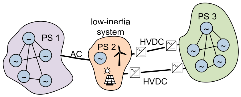
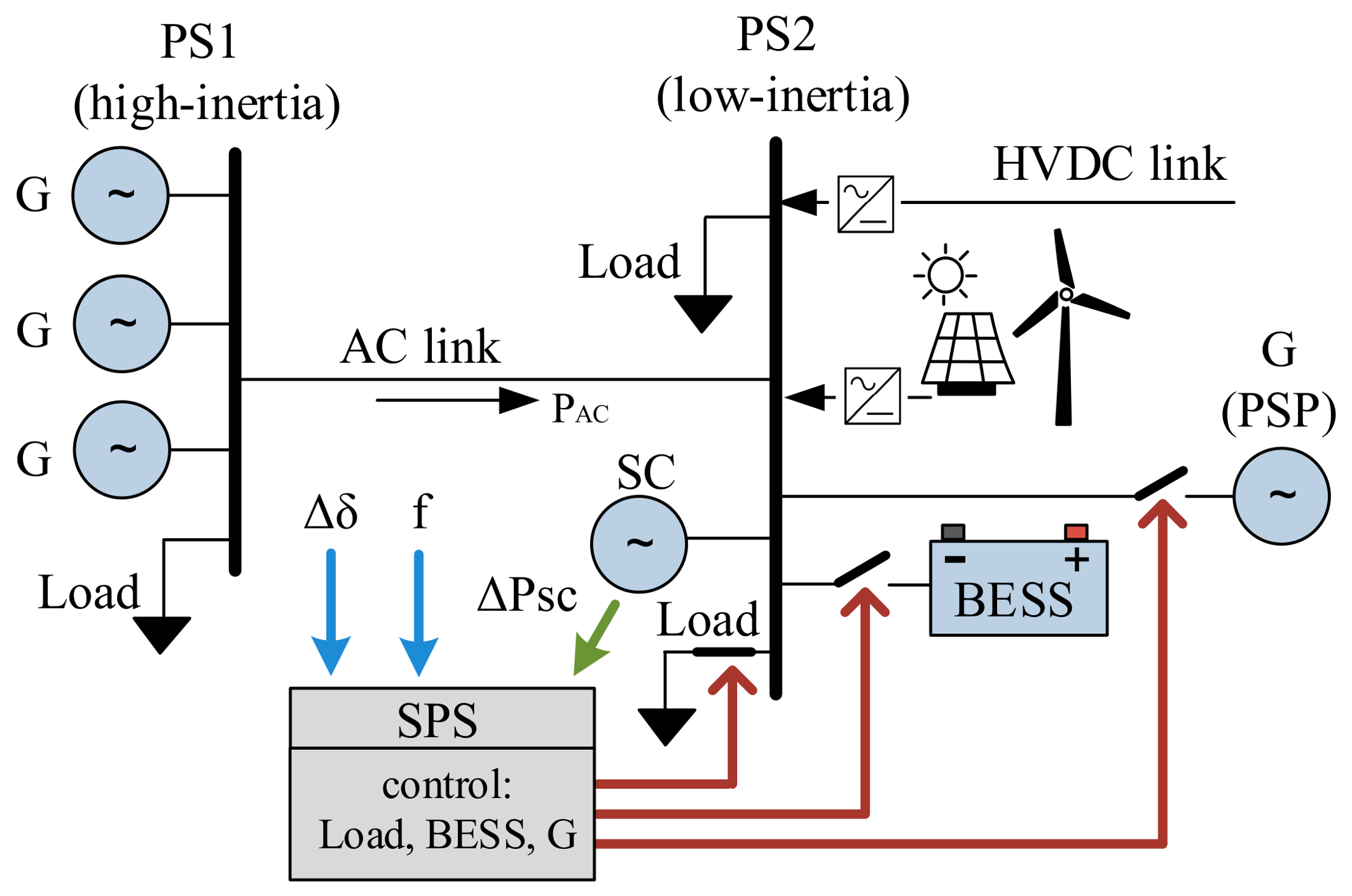
PS stability, including frequency, angular, voltage, and thermal stability [4,35], is particularly vulnerable in low-inertia power systems that are weakly interconnected with neighboring grids. Figure 1 illustrates the studied power system, consisting of a subsystem PS2 connected to a larger subsystem PS1 through a high-voltage alternating current (AC) transmission line (TL), while another subsystem, PS3, is connected through high-voltage direct current (HVDC) links.
Subsystem PS2 is assumed to employ synchronous condensers, pumped-storage units, or battery energy storage systems, together with special protection schemes, to support PS stability under low-inertia operating conditions. At the same time, the grid operator seeks to minimize generation costs while maintaining secure and reliable system operation.
This paper analyzes the stability of subsystem PS2 under three large-scale disturbance scenarios:
  • Sudden disconnection of an HVDC link, transferring a significant amount of power to PS2;
  • Sudden disconnection of a major generator within PS2;
  • The above-mentioned contingencies with AC TL not in service or in service with a variable degree of link loading.
Each of these events may lead to a severe power imbalance, potentially causing a rapid frequency decline, loss of synchronism, and ultimately a system-wide blackout if not properly mitigated. To prevent such outcomes, conventional operational practices typically require either constraining the available capacity of generation and transmission assets or maintaining a minimum share of synchronous generation to increase PS inertia.
However, both approaches introduce significant operational and economic drawbacks. Capacity constraints limit energy delivery and reduce market efficiency, while maintaining high levels of synchronous generation may conflict with the increasing penetration of low-cost renewable resources. Therefore, new stability enhancement strategies are required to ensure system security without imposing economically burdensome constraints on system operation.
The development of such strategies begins with a mathematical representation of system dynamics, typically expressed through a set of differential equations describing generator electromechanical behavior [7,10,32]. This study considers a network of n synchronous machines and the transient angle and frequency dynamics that arise following the loss of a large generator. For each machine i, rotor motion is described by the nonlinear swing equation.
In this work, we use the simplified form of these equations, assuming idealized dynamics. We do not account for damping effects, load frequency response, or other secondary control mechanisms. This simplification allows us to focus on the fundamental inertial behavior and angle dynamics immediately following the disturbance [36].
2 H i ω 0 d 2 δ i d t 2 = P m i P e i ,
where H i is the inertia constant (s), representing the time that the machine could supply its rated power solely from its stored kinetic energy; δ i is the rotor angle of machine i; P m i and P e i are the mechanical and electrical power.
Although each generator has its own swing dynamics, electrical coupling arises because the electrical power output P e i depends on the relative rotor angles between generators. For a network of n generators interconnected through transfer admittance Y i j , the electrical power output of machine i can be expressed as [36]:
P e i = j = 1 n n · E i · E j · Y i j · s i n ( δ i   δ j   θ i j ) ,
where E i ,   E j are the magnitudes of internal voltages at buses i and j ; Y i j is the magnitude of the admittance between buses i and j ; δ i ,   δ j are the voltage angles at buses i and j ; θ i j is the phase angle of the transfer admittance between buses i and j .
Relative rotor angles determine the power exchange between machines and, therefore, the synchronizing torque that maintains system stability. The instantaneous frequency of the generator can be expressed as [36]:
f i t = f s + 1 2 · π d δ i d t ,
where f i t is the instantaneous frequency of machine i ; f s is the system synchronous frequency; δ i is the rotor angle deviation of generator i ; t is the time variable.
The objective of this work is to identify and mitigate dangerous oscillatory modes—both local and inter-area—that may be initiated by generator or transmission line outages. Addressing these stability challenges requires an understanding of system-level dynamic processes and the application of control technologies that are capable of effectively damping or preventing such oscillations. These processes are typically described by swing equations representing the electromechanical behavior of synchronous machines. Solving these equations can be challenging because it requires accounting for multiple generators, transmission lines, loads, and the effects of automatic control systems during transient conditions. In practice, Transmission System Operators perform such analyses by using specialized commercial simulation platforms. However, for conceptual understanding and to illustrate the fundamental behavior of the system and the underlying stability challenges, a simplified analytical model can be employed.
Consider power subsystem PS2, which comprises predominantly non-inertial generation sources together with a synchronous generator and a synchronous condenser providing moderate system inertia (Figure 1). Subsystem PS2 imports power from the larger power system PS1 through an AC interconnection, where PS1 can be approximated as an infinite bus. In addition, PS2 imports power from subsystem PS3 through HVDC links operating at full power transfer capacity and, therefore, is unable to provide frequency support to PS2. Now consider a contingency that results in a significant power deficit in PS2, such as the sudden disconnection of a large generation unit within PS2 or the loss of the DC interconnection with PS3. By aggregating the dynamics of PS2 and modeling its interaction with the infinite bus of PS1, the swing equation can be used to describe the electromechanical oscillations as follows:
2 · H i f 0 d f d t = P m t + P m a x · sin δ t , d δ d t = 2 · π · f t     f 0
with the initial conditions:
f 0 = f 0 ,   δ 0 = δ 0 = arcsin P m 0 / P m a x ,   P m 0 = P m a x · sin δ 0 ,
where P m 0 denotes the equivalent net input power of PS2, δ 0 is the steady-state power angle between the internal voltage of PS2 and the infinite bus, δ t is power angle difference between PS2 and the infinite bus PS1, f 0 is the nominal system frequency; P m a x is the maximum power transfer of an AC transmission line. A disturbance at time t = t0 is represented as:
P m t = P m 0   i f   t < t 0 ,   a n d   P m t = P m 0 + P d i s t   i f   t t 0 ,
where P d i s t represents the imbalance between mechanical input and electrical output power in the case of a disturbance. The model represents PS2 as an equivalent single machine connected to an infinite bus, where frequency deviations are driven by power imbalance and nonlinear AC power transfer. The main simplifications include aggregation of system inertia, infinite bus representation of PS1, lossless AC power transfer, neglect of voltage and reactive power dynamics, constant-power HVDC operation, and omission of droop control and damping.
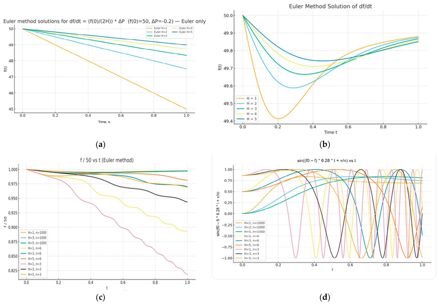
Figure 2a–d illustrate the response of power system PS2 to a large generator outage.
Figure 2a shows the PS2 response to a generator outage when the AC transmission line is disconnected. Simulations were carried out for t < 1   s , with an initial frequency f 0 = 50   H z . Calculations were performed for inertia constant values H = 1 ,     2 ,     3 ,     4 ,   a n d   5   s . Here, H = 5   s represents a conventional synchronous-generator-dominated system, while H = 1   s reflects a low-inertia system with a high share of renewable generation. The system was subjected to a power imbalance of P = 0.2   p u , with the maximum power transfer of AC TL (see Figure 1) set to P m a x = 0.3   p u . Following the generator outage, the system frequency decreases, and the rate of decline strongly depends on the system inertia. For low values of the inertia constant H , the frequency reaches critical levels within approximately 400 ms, indicating reduced capability of the system to withstand sudden disturbances under low-inertia conditions.
Figure 2b shows the same disturbance with the AC TL in service. In this scenario, where the AC TL is energized but carries no power prior to the disturbance, PS behavior improves, and power support from PS3 contributes to maintaining the frequency in PS2.
Figure 2c,d demonstrate the influence of AC TL power transfer on PS stability. When the line is heavily loaded prior to a generator outage, the PS frequency drops significantly, and an out-of-step condition may occur, leading to a loss of synchronism and overall PS instability. The power swings associated with this out-of-step behavior, described by the sinusoidal power transfer characteristics, are illustrated in Figure 2d.
It should be noted that the simplified schematic model used in this example is intended to clearly demonstrate the essence of the proposed approach. In general, the approach can be extended to more complex PS configurations [37].

2.2. Grid Stability Support Technologies

Synchronous Condensers as Real-Time Sensors of System Imbalance. SCs are widely used to increase PS inertia. A sudden shortage of active power leads to the deceleration of SC’s rotating mass. The SC’s accumulated kinetic energy is transformed into electric energy and injected into the electrical grid. Such an inertial response maintains the electrical power balance immediately after the transient, reduces the ROCOF, and helps stabilize PS frequency before primary frequency control take an action. The active power response of the synchronous condenser can be approximated as:
P S C t = 2 · H S C ω 0 d ω S C d t ,
where H S C . is the inertia constant of the SC (s); ω S C is the angular speed of the SC.
Continuous and precise monitoring of SC active power injections provides an immediate and reliable measure of disturbance severity. This information forms a robust basis for the prompt activation of remedial actions, such as rapid load shedding (RLS) or SPSs, which are intended to restore the balance between generation and consumption, recover the nominal system frequency, and prevent thermal and stability-related overloads of transmission lines.
In this context, SC-based SPSs shall be capable of executing fast balancing actions, primarily through the coordinated operation of deployed energy storage systems, enabling rapid active power injection or absorption in response to power imbalance. Building on the requirement for fast balancing actions enabled by SC-based SPSs and the coordinated operation of deployed energy storage systems, the subsequent control layer must ensure system stability not only in terms of frequency but also with respect to rotor angle dynamics. In particular, effective management of rotor angle excursions following large disturbances is essential to maintain synchronism and prevent cascading outages. Accordingly, the following section focuses on the formulation of an SPS operation algorithm based on rotor angle control, which leverages the fast-acting capabilities of synchronous condensers and associated resources to detect critical angular deviations and trigger appropriate corrective actions.
Rotor Angle Stability Enhancement via SC-Based Monitoring. This approach exploits the dynamic response of SC to detect and mitigate rotor angle deviations in interconnected power systems. Incorporating SC-derived measurements into system monitoring and control loops improves angular stability and enhances oscillation damping, particularly under low-inertia operating conditions [32,38].
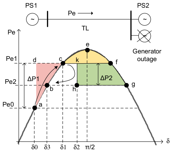
For the example presented in Figure 3, it is assumed that PS2 is ready to import energy from PS1, where the energy price is lower. However, the TL capacity is limited due to angle stability constraints and the potential risk of a major generator outage [32,39].
By observing the rotor angle deviation (dδ/dt) and estimating the power imbalance ΔP from the SC’s dynamic response, operators can obtain a reliable trigger for protective measures. Moreover, this information enables effective PS restoration by promptly activating a generator with sufficient reserve capacity [38].
This principle is illustrated in the interaction between two connected systems, PS1 and PS2. Under normal conditions, part of the PS2 load is supported by importing power Pe0 from PS1 via the TL (point “a” in Figure 3). In the event of a sudden outage of the major generation source in PS2, a power deficit ΔP1 occurs, triggering several events. Immediately following the generation loss, the deficit ΔP1 is redistributed among the remaining generators in PS2 and PS1 (Figure 3). The kinetic energy stored in the rotating masses of generator rotors provides only a temporary contribution to power balance and does not prevent continued frequency deceleration. As a result, the generators further decelerate, leading to a sustained decline in system frequency and an increase in the rotor angle δ. This progression increases the risk of an out-of-step condition and may ultimately lead to PS instability or blackout.
To prevent such a dangerous scenario, it is essential to quickly restore power balance by compensating for the lost generation capacity. In Figure 3, two cases are shown. The first assumes the occurrence of an imbalance at point “a”. According to the equal area method [4], conditions for asynchronous operation arise, since the acceleration area “abcd” (red area) is greater than the braking area “cef” (yellow area). However, the braking area can be increased by injecting energy (green area), for example, at point “k” (angle δ2). One effective method for achieving this is through the use of PHS units operating in a special emergency regime or high-capacity batteries [32].
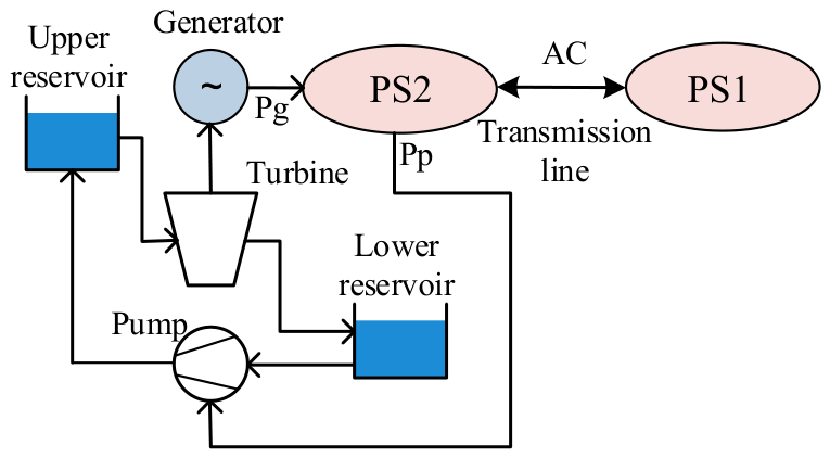
Emergency Control Strategy for Pumped Hydroelectric Storage Plants. An emergency control system can be implemented using PHS units (see Figure 4) [32], which are capable of simultaneous operation in pumping and generation modes. This operating mode is non-conventional and leads to net energy losses, as the plant consumes more energy than it produces. Nevertheless, this regime is introduced in anticipation of critical system events. By being activated while the PS is still operating normally, it provides rapid and flexible power balancing capability at the moment a disturbance occurs, thereby enhancing PS stability and preventing the development of severe consequences such as widespread load shedding or PS collapse. Furthermore, the presence of this fast-acting control regime increases the TL permissible loading, allowing higher normal operating capacities while maintaining acceptable security margins. The method’s speed is achieved through the physics of the hydraulic circuit: in the selected mode, the turbine–generator set is already spinning synchronously with the grid. Rapid power injection is, therefore, achieved simply by disconnecting the pump from the water circuit, allowing the PSP to transition immediately to full generation mode. This switching process takes only tens of milliseconds—far faster than starting a unit from rest. By enhancing the dynamic response capabilities, the approach contributes significantly to grid stability. Under certain emergency conditions, the potential for swift control actions and associated economic benefits makes this strategy particularly attractive.
Comparable performance could also be achieved with high-capacity BESSs, provided [23] that they can be rapidly connected to the grid and discharged to directly supply the required power following an unexpected generation loss. Such fast energy injection plays a key role in limiting initial frequency and rotor angle deviations, thereby providing the time margin required to activate slower reserve resources, such as hydroelectric generation, and to restore a secure operating regime of the PS after an N-1 contingency.
These considerations underscore the need to systematically translate fast dynamic responses into coordinated corrective actions within the available time margin following a disturbance. Accordingly, a novel SPS framework is introduced (see Figure 5). The active power balance of PS2 is supported by an AC link connecting it to the larger and more robust power system PS1, which provides essential frequency and power support.
The scheme exploits the real-time active power response ΔPsc of the synchronous condenser, the system frequency f, and the rotor angle deviation Δδ to anticipate impending stability disruptions.
Controllable resources, such as PHSs and/or BESSs, together with reserve generators, are coordinated through the SPS. The SPS utilizes SCs as indicators of power system imbalance and acts to extend the available time window for the activation of reserve generation.
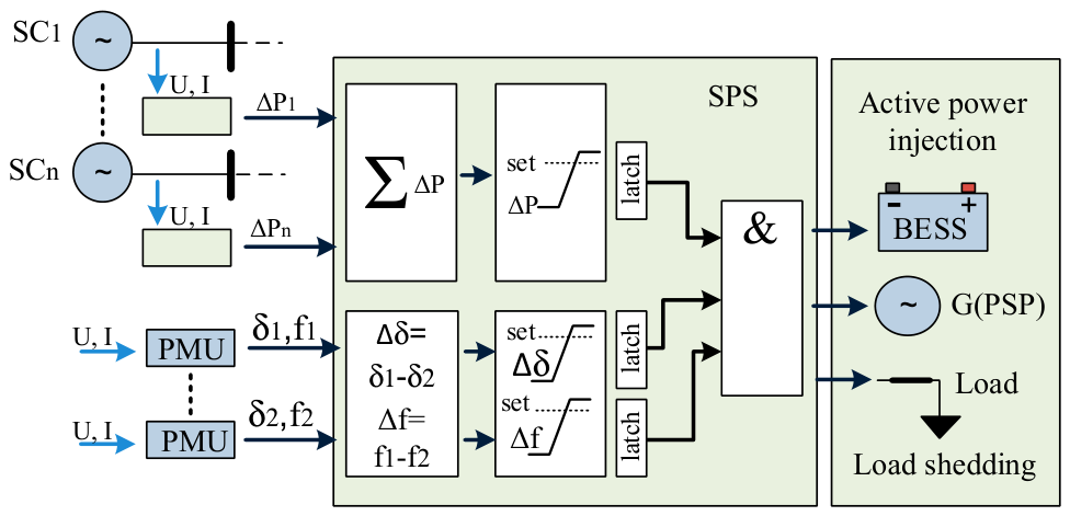
Figure 6 presents a simplified architecture of the SPS, which uses real-time measurements of the SCs’ power injection ΔPn, angles along the major interconnection link δ1 and δ2, and frequencies f1 and f2 of the PS1 and PS2 systems.
The proposed power injection control strategy employs a look-ahead decision-making mechanism. The aggregated power injection ∑ΔP(t), angular difference Δδ(t) = δ1 − δ2, and frequency difference Δf(t) = f1 − f2 are estimated from real-time measurements and stored in an appropriate, updated process monitoring window. The length of such a window should be long enough to contain both the value of ∑ΔP at the moment when power was injected, and the monitoring window must be long enough to fix and contain slowly varying Δδ and Δf. The time moment of the power injection is stated by comparing the current value of ∑ΔP(t) against a predefined threshold ΔPset. If the threshold is exceeded, the current ∑ΔP(t) will be latched and will serve as a reference value of power imbalance, which will be used further for estimation of the amount of corrective actions needed. Exceeding the ΔPset triggers the evaluation of Δδ > Δδset and Δf > Δfset conditions and, if both conditions are satisfied and latched within the process monitoring window, the corrective control actions will be taken. Thereby, the power imbalance corrective actions will be taken if all three conditions: ∑ΔP(t) > ΔPset, Δδ > Δδset, Δf > Δfset are fulfilled within the process monitoring window.
Among various possible corrective actions, controllable resources with fast adjustment/injection of active power are preferable. That is, activation of PHSs, BESSs, or, in a worst-case scenario, preventive load shedding.

3. Case Description

3.1. System Under Study

Dynamic and market simulations are performed on a simplified model representative of the Baltic power system, designed to capture its key challenges and transition tendencies while maintaining analytical transparency. This system is chosen not only for its readiness to implement SPS but also because it exemplifies the operational and stability challenges faced by rapidly decarbonizing power grids, as noted in [40], with these changes influenced, in part, by broader policy and geopolitical factors.
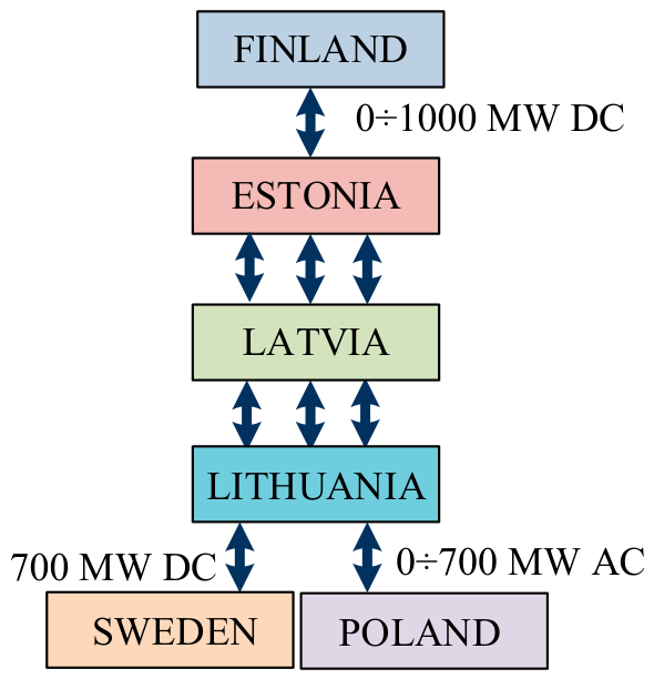
The Baltic states operate a meshed 330 kV transmission grid with a peak load of approximately 8000 MW [16], interconnected asynchronously via HVDC links to Finland, Sweden, and an AC link to Poland (Figure 7). The synchronous interconnection to the ENTSO-E grid via a 400 kV double-circuit AC line between Lithuania and Poland (hereafter referred to as the LT–PL tie-line, with a thermal capacity of approximately 2000 MW) is now operational [17]. This enhances PS stability, but outages on this line would still force the Baltic grid to operate in island mode, relying solely on local inertia reserves.
As of 2025, key developments in the Baltic PS have been realized: approximately 4000 MW of wind generation and 5000 MW of solar generation have been installed [20]. Grid flexibility is provided by conventional hydropower plants (aggregate installed capacity of approximately 1500 MW) and PHS units (total rated capacity of 1000 MW across four generating units). Dispatchable hydro units provide rapid start-up capability, achieving synchronization within approximately 120–180 s. Nevertheless, despite these fast-response resources, dynamic stability margins remain constrained during periods of high VRES generation, increasing the risk of frequency deviations and rotor angle instability. To address this challenge, nine synchronous condensers, each rated at approximately 100 MVA and collectively providing 18 GW·s of kinetic energy, have been commissioned [39]. Furthermore, BESSs with a combined power capacity exceeding 500 MW and a total energy storage volume of 1000 MWh are already operational or scheduled for commissioning within the coming month. Even so, stability margins remain tight during high renewable output, with elevated risks of frequency and rotor angle instability.
These risks are amplified by interconnection constraints. The potential loss of the Poland–Lithuania or Sweden–Lithuania link limits allowable transfers on the Poland–Lithuania AC corridor, as sudden outages could cause frequency deviations, thermal overloads, or angular instability. To maintain security, transfer limits are set well below thermal ratings, ensuring sufficient capacity for emergency injections. In practice, stability considerations, rather than conductor capacity, define permissible flows.
The implementation of advanced SPS offers a potential solution to alleviate this limitation and enable more efficient utilization of the interconnection.
Below, we present results assessing whether the implementation of an SPS can support an increase in the permitted capacity of the Lithuania–Poland (LT/PL) interconnection.

3.2. Single-Area Frequency Response Model with Tie-Line

Based on the Baltic PS, reviewed in Section 3.1, a simplified single-area frequency response model (see Figure 1) with a tie-line (Poland–Lithuania AC link) is considered. The model includes aggregate inertia, droop-based primary frequency control, first-order governor dynamics, and a simplified SPS model, represented by threshold-based logic based on SCs power injection, frequency, and angle measurements.
By aggregating the dynamics of PS2 and modeling its interaction with the infinite bus of PS1 (see Figure 1), the swing Equation (4) is used to describe the electromechanical oscillations of the equivalent generator of PS2. All simulations are performed in the per-unit (p.u.) system, allowing normalization of power, inertia, and load parameters. The base values are selected as the nominal system frequency f0 = 50 Hz, and the total aggregated system load is 10 GW, ensuring a physically meaningful scaling of the swing equation. It is assumed that the system inertia of the PS2 is mainly provided by the SCs. Given the total kinetic energy stored in the synchronous condensers, E = 20,000   M W s , the equivalent inertia constant of the system H can be determined as H = E / S b a s e = 20,000 / 10,000 = 2   s .
Prior to the disturbance, mechanical power, load, and tie-line power flow satisfy an exact power balance, ensuring constant frequency. The most severe stability-critical events considered are the tripping of heavily loaded interconnections, including the AC Lithuania–Poland tie-line, as well as the Lithuania–Sweden and Estonia–Finland HVDC links (Figure 1, Figure 7), which may cause a sudden power deficit of up to 1000 MW, corresponding to Δ P = 0.1   p . u . on a 10 GW base.
The dynamic behavior of PS frequency is governed by the swing equation expressed in Hz form, combined with a static droop governor and a first-order actuator lag. The tie-line power flow is modeled as a sinusoidal function of the angle difference between the PS2 area and the infinite bus PS1. In view of the threat of loss of angular stability (see Figure 2), the rotor angle difference between PS1 and PS2 is considered critical once it reaches −π/2. A disturbance is applied at t = 1 s to assess system dynamics and SPS performance.
The SPS is activated when all of the following conditions are simultaneously satisfied:
P S C > S 1 f > S 2 φ + δ < S 3 ,
where P S C is the aggregate active power injection of the PS2 SCs, f is the frequency difference between Poland and Lithuania, δ is the rotor angle deviation relative to Poland, and φ is the pre-disturbance tie-line angle. Settings S1, S2, and S3 are predefined SPS thresholds defined as S 1 = 0.08   p . u . S 2 = 0.2   H z S 3 = 90 ° .
The thresholds S1 and S2 are selected to prevent SPS activation during small disturbances while ensuring reliable triggering under large disturbances. The angle threshold S3 = −90° is based on the well-known stability limit, as rotor angle differences approaching 90° are typically associated with a loss of synchronism. These values are chosen to demonstrate feasibility within the simplified modeling framework rather than through detailed optimization. Regarding the process monitoring window, its length is assumed to be in the range of 1–2 s, as primary frequency control acts within this time frame following a disturbance.
Upon activation, the SPS triggers a predefined corrective action, modeled as controlled load shedding.

3.3. Model Equations and Simulation Setup

This section describes the mathematical model and numerical method used to obtain the frequency response results for the disturbance case. The PS is represented by a single-area equivalent generator connected to an infinite bus through a tie-line. Frequency dynamics are modeled using the swing equation with primary frequency control (governor droop). All power quantities are expressed in per unit (p.u.) on a common MVA base.
1. Tie-line power:
The electrical power exchanged over the tie-line is given by:
P t i e , k = P m a x · sin φ + δ k ,
where P m a x is the maximum tie-line power coefficient, φ is the steady-state angle offset, and δ k is the rotor angle at time step k.
2. Governor droop characteristic:
Primary frequency control is modeled using a linear droop characteristic:
P m , k = P m 0   1 R f k f 0 f 0 ,
where P m 0 is the mechanical power reference, R is the droop coefficient, f k is the system frequency, and f 0 is the nominal frequency.
The delayed response of the generation is modeled using a first-order lag with a time constant T g . Using the forward Euler method, the mechanical power is updated as:
P m , k + 1 = P m , k + t T g P m , k   c m d P m , k ,
P m , k   c m d denotes the mechanical power command generated by the droop controller, while the actual mechanical power P m , k follows this command through first-order governor dynamics characterized by the time constant T g .
3. Frequency update (swing equation):
The discrete-time swing equation is integrated using the Forward Euler method:
f k + 1 = f k + t f 0 2 · H · P m , k P L P t i e , k ,
where H is the inertia constant, t is the integration time step, and P L is the load power.
4. Rotor angle update:
The rotor angle relative to the infinite bus is updated as:
δ k + 1 = δ k + 2 · π · t · f k f 0 ,
The pre-disturbance operating point is balanced by setting P m 0 = P L 0 + P m a x · sin φ , where P m 0 = 1   p . u . and is the total active power of the system, P L 0 —the PS2 system generated power and P m a x · sin φ is active power imported from PS1 over the tie-line.
Table 1 summarizes the main parameters used in the single-area frequency response simulations.

3.4. Examples

Using the modeling framework and numerical implementation described in Section 3.3, a set of representative simulation examples is presented below. The selected cases highlight the main dynamic characteristics of the system and the effectiveness of the proposed SPS.
Example No 1: Generator outage.
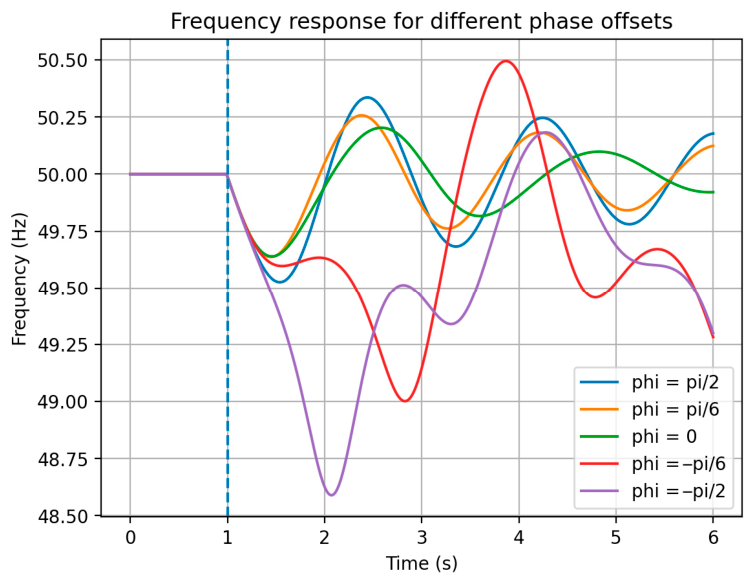
Initially, the post-contingency behavior of the power system is examined under conditions with variable loading of the tie-line (φ = −π/6, −π/2, 0, π/6, π/2) and in the absence of any SPS. The resulting frequency deviations are shown in Figure 8. The disturbance time t = 1 s is shown by a dashed vertical line.
The presented results indicate that stability problems become pronounced when the tie-line is heavily loaded under power import conditions, corresponding to large negative steady-state angle offsets (e.g., φ = −π/2 or φ = −π/6). In these cases, the system exhibits increased sensitivity to disturbances, leading to significant frequency deviations and degraded dynamic performance.
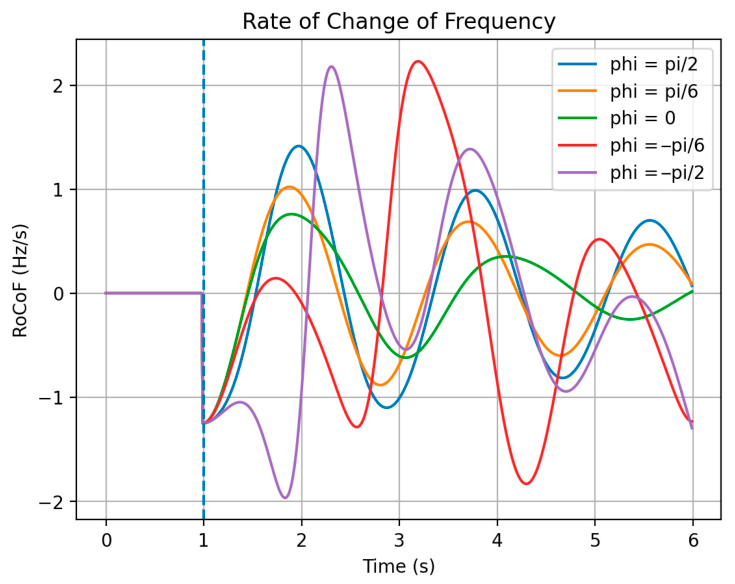
The initial ROCOF jump (see Figure 9) is the same for all scenarios and is governed by the disturbance magnitude. The disturbance time t = 1 s is shown by a dashed vertical line. In contrast, the post-disturbance ROCOF evolution depends on the pre-fault tie-line loading.
This indicates that, beyond disturbance size, parameters associated with tie-line loading must be considered to detect hazardous operating conditions.
Example No 2: Generator outage followed by SPS action.
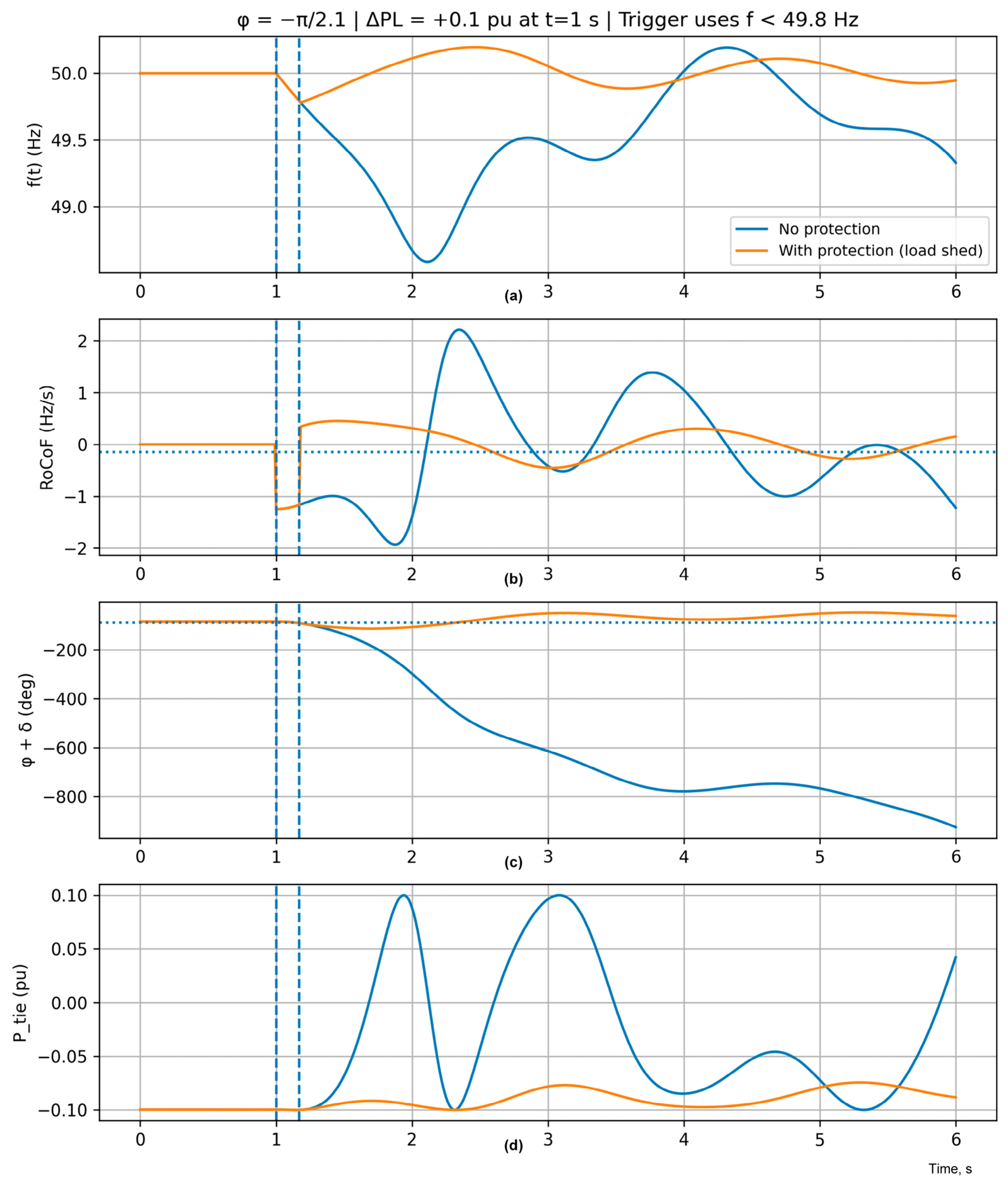
Figure 10 illustrates the dynamic response to a post-contingency power deficit of ΔPL = 0.1 p.u., which occurs in PS2 at t = 1 s. The disturbance time t = 1 s is shown by a dashed vertical line. The threshold lines are dotted. A SPS is implemented to mitigate the system response following the disturbance. Once activated, the SPS executes a latched control action that sheds the load by ΔP = 0.12 p.u.
Two subcases are considered: PS operation without a SPS (blue color) and with a SPS enabled (orange color). The results show that the SPS prevents loss of synchronism, which is clearly indicated by the unbounded increase of the rotor angle deviation δ in the case without protection. The resulting system response demonstrates the effectiveness of the SPS in limiting frequency deviation and improving post-disturbance stability. A detailed analysis of the SPS action and its impact is provided in the subsequent examples.
Example No 3: Tie-line trip event followed by SPS action.
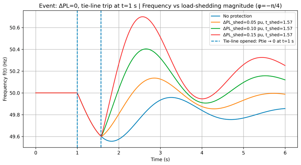
This example considers a balanced single-area power system connected to an infinite bus via a tie-line with an initial phase offset of φ = −π/4. At t = 1 s, the tie-line is assumed to trip (left dashed vertical line), resulting in a sudden loss of interconnection and creating a power deficit of ΔPL = 0.07 p.u.
The system frequency response is evaluated for the case without protection and compared with cases where SPS-based load-shedding is activated at t = 1.57 s (right dashed vertical line), using three different shedding magnitudes: 0.05 p.u., 0.1 p.u., and 0.15 p.u (see Figure 11).
The results show that the activation of load shedding mitigates the frequency deviation following the tie-line trip and improves post-disturbance dynamic behavior. These observations indicate that the application of SPS-based RLS enhances system stability in this scenario as well.
Example No 4: Frequency response for different load-shedding magnitudes under high tie-line loading.
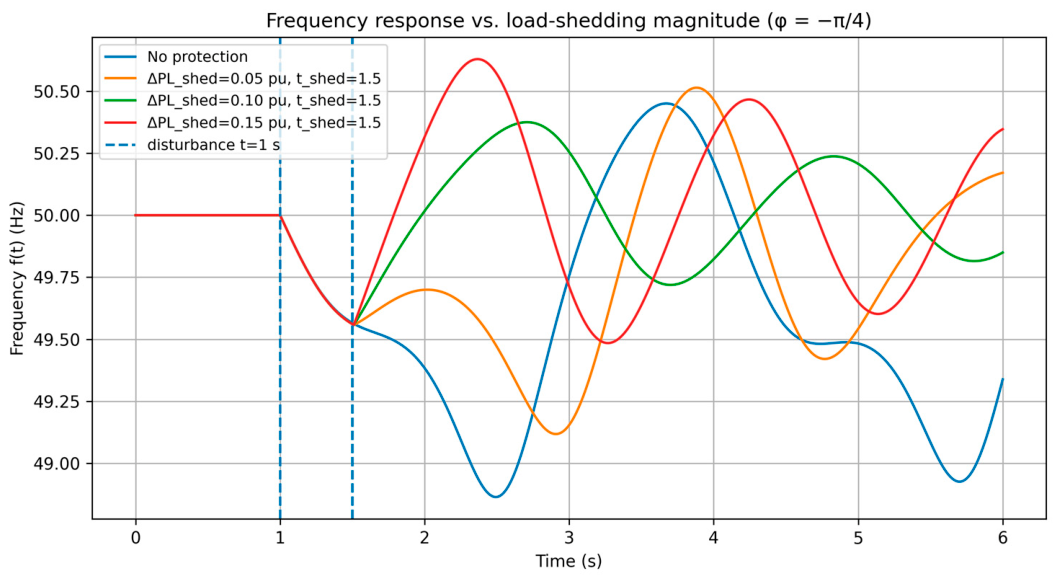
In this example, the power deficit of ΔPL = 0.1 p.u. arises as a result of a sudden generation outage within PS2 at t = 1 s. Before contingency, the tie-line is loaded close to its maximum allowable limit, corresponding to an initial phase offset of φ = −π/4. The system is, therefore, operating near a critical power transfer condition prior to the disturbance. The system frequency response is evaluated for the case without protection and compared with cases employing a latched load-shedding scheme using multiple shedding magnitudes.
The results (Figure 12) indicate that, under high tie-line loading, the activation of SPS-based RLS can preserve system stability. Both excessive and insufficient load shedding lead to less favorable dynamic behavior, highlighting the importance of appropriate SPS parameter selection under heavily loaded tie-line conditions. In contrast, the frequency behavior without SPS activation (blue line) clearly demonstrates the loss of synchronism and angular instability.
Additional examples of conventional UFLS and RLS operations are demonstrated in [41,42].
Example No 5: Measured response of the system and synchronous condenser to a major disturbance.
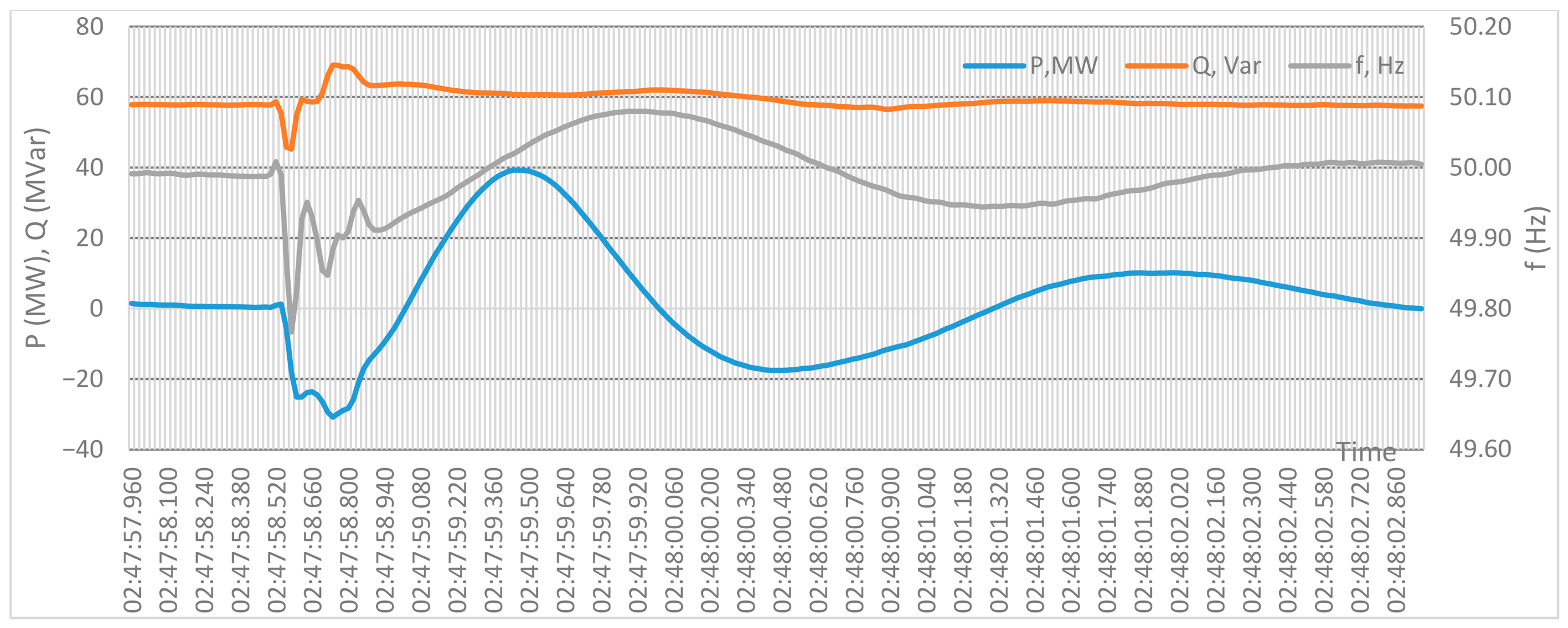
This example presents the measured frequency of the PS and SC responses to a large real disturbance in Baltic PS that occurred in October 2025 (Figure 13), during which a generation source of approximately 600 MW was disconnected. The recorded PS response is shown without additional post-processing.
The active power contribution of a single synchronous condenser is approximately ΔPsc ≈ 30 MW. Considering the aggregated active power response of all nine SC units, a significant part of the total power deficit will be covered by SCs at the initial moment after the disturbance.
The qualitative characteristics of the measured responses are consistent with the trends observed in the simulation results presented in the previous examples, indicating no contradiction between the simulated and recorded PS behavior under large disturbances.
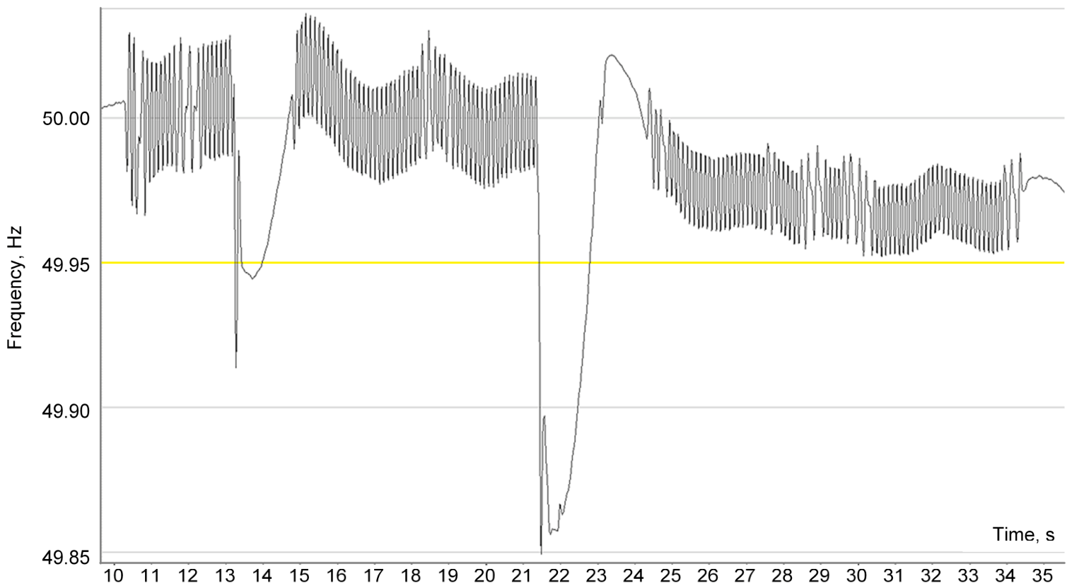
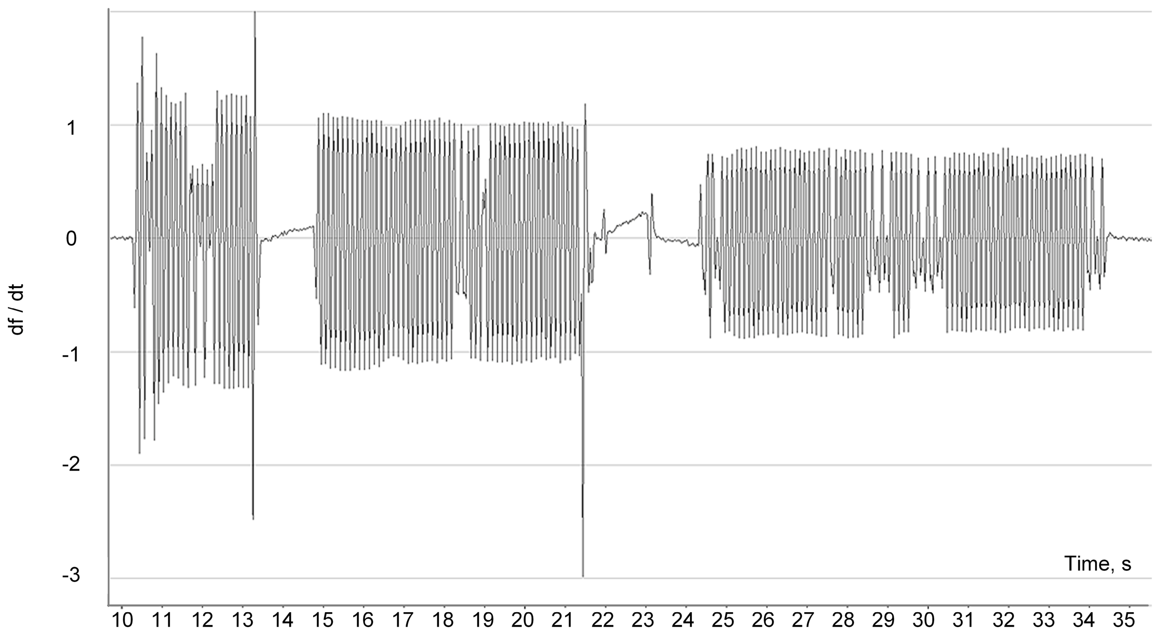
Figure 14 and Figure 15 present the PMU-measured Baltic PS frequency response to other disturbances that occurred in January 2026, during which generation sources of approximately 300 MW and then 600 MW were disconnected sequentially within a short period of time. The yellow line indicates a 0.1% drop, highlighting a near-critical operating zone.
The qualitative characteristics of the measured response correlate well with the simulation results. It is important to note the presence of measurement noise in the df/dt (ROCOF) signals. The existence of this noise highlights the relevance of replacing direct df/dt measurements with active power injection measurements from synchronous condensers [43,44].

4. Discussion

The results presented in this paper demonstrate the potential of an enhanced SPS framework that combines SC active power injection measurements, rotor angle information, and frequency-based indicators with fast-responding resources intended to restore power balance and avoid loss of stability. By integrating synchronous condensers with active power injection capabilities and coordinated control logic, the proposed approach addresses key challenges associated with reduced system inertia and increased vulnerability to large disturbances.
The use of simplified power system models enables a focused examination of the dominant dynamic mechanisms governing system response. In particular, the simulations highlight how pre-disturbance operating conditions—such as tie-line loading and phase-angle margins—strongly influence post-disturbance frequency and stability behavior. This observation underscores the limitations of protection schemes based solely on frequency or ROCOF thresholds and motivates the inclusion of additional state variables related to power transfer and angular stability.
The incorporation of fast-response resources, including synchronous condensers, PHS, and BESS, allows the SPS to deliver corrective active power support within the critical early moments following a disturbance. The analyzed scenarios indicate that appropriately sized and coordinated responses can significantly improve system trajectories, especially under heavily loaded or near-critical operating conditions. At the same time, the results illustrate that excessive or poorly tuned corrective actions may lead to unfavorable dynamics, emphasizing the importance of adaptive and context-aware SPS settings.
Measured disturbance data further support the qualitative validity of the proposed framework. The observed system responses during real large-scale generation outages exhibit dynamic characteristics that are consistent with the simulated behavior, particularly with respect to the timing and magnitude of active power contributions. The presence of noise in df/dt measurements highlights practical challenges in real-world implementations and reinforces the motivation for using active power measurements from synchronous condensers as a more robust control input. The practical realization of the proposed SPS framework requires the availability of sufficiently large capacities of rapidly injectable power. The effectiveness of the corrective actions depends not only on the detection logic, but also on the capability of the system to deliver active power within the first seconds following a disturbance. In this context, PHS units and large-scale battery energy storage systems are particularly well suited, as they can provide high power output with fast response times and controllable activation characteristics.
The results indicate that, when adequate fast-response capacity is available, the SPS can significantly influence post-disturbance dynamics and limit the development of severe stability issues. Conversely, insufficient injectable power may constrain the achievable benefits of SPS operation, highlighting the importance of coordinated planning between protection schemes and fast-response resource deployment.
Overall, the discussion confirms that the proposed SPS framework provides a coherent and physically grounded approach for enhancing transient stability in low-inertia power systems, while maintaining transparency and interpretability of the underlying control mechanisms

5. Conclusions

This paper proposes an enhanced SPS to support transient stability in low-inertia power systems by combining synchronous condensers, frequency and rotor angle monitoring, and fast-response resources such as pumped hydro storage and battery energy storage. Using deliberately simplified system models, this study explores how coordinated corrective actions influence system dynamics under major disturbances. The results indicate that operating conditions, particularly tie-line loading and angular margins, play a key role in post-disturbance behavior, and that appropriately scaled corrective power injections can help maintain stability in the examined scenarios. The proposed approach enables early detection of hazardous operating conditions and coordinated corrective actions, which can prevent severe disturbances. The analysis highlights the advantages of using active power measurements from synchronous condensers compared to ROCOF-based indicators. Qualitative consistency with selected PMU observations suggests the approach captures relevant dynamic features, while highlighting potential advantages of active power-based measurements over ROCOF in noisy environments. The results also indicate that the effectiveness of the SPS depends on the availability and proper sizing of fast-response resources. Overall, the framework demonstrates feasibility and provides insight, but further validation using higher-fidelity models is required to quantify performance and practical impact.

Author Contributions

Conceptualization, A.S.; methodology, A.S., A.U., D.Z., and G.J.; formal analysis, A.S., A.U., D.Z., and G.J.; writing—original draft preparation, A.S.; writing—review and editing, A.U., D.Z., G.J., and G.B.; visualization, A.S., A.U., D.Z., G.J., and E.E.; supervision, A.S. All authors have read and agreed to the published version of the manuscript.

Funding

This research was funded by the Latvian Council of Science, project No. Lzp-2023/1-0376 “Innovative emergency control of RES-dominated low-inertia power systems (INNOVA)”.

Data Availability Statement

The data presented in this study are available on request from the corresponding authors. The data are not publicly available due to restrictions related to critical energy infrastructure.

Conflicts of Interest

Author Gatis Junghans was employed by the company Augstsprieguma tīkls, AS. The remaining authors declare that the research was conducted in the absence of any commercial or financial relationships that could be construed as a potential conflict of interest.

Abbreviations

The following abbreviations are used in this manuscript:
ACAlternating current
BESSBattery Energy Storage Systems
CO2Carbon dioxide
HVDCHigh-voltage direct current
PHSPumped hydroelectric storage
PSPower system
RASRemedial action scheme
RLSRapid load shedding
ROCOFRate of change of frequency
SCSynchronous condenser
SPSSpecial protection scheme
TLTransmission line
TSOTransmission System Operators
UFLSUnder-frequency load shedding
VRESVariable renewable energy sources

References

  1. EC 2030 Climate and Energy Policy Framework EUCO 169/14. 2014. Available online: https://data.consilium.europa.eu/doc/document/ST-169-2014-INIT/en/pdf (accessed on 27 January 2025).
  2. International Energy Agency. Global Energy Review 2025; IEA Publications International Energy Agency: Paris, France, 2025; p. 43. [Google Scholar]
  3. Shukla, P.R.; Skea, J.; Reisinger, A.R.; IPCC. (Eds.) Climate Change 2022: Mitigation of Climate Change; IPCC: Geneva, Switzerland, 2022; ISBN 978-92-9169-160-9. [Google Scholar]
  4. Hatziargyriou, N.; Milanovic, J.; Rahmann, C.; Ajjarapu, V.; Canizares, C.; Erlich, I.; Hill, D.; Hiskens, I.; Kamwa, I.; Pal, B.; et al. Definition and Classification of Power System Stability—Revisited & Extended. IEEE Trans. Power Syst. 2021, 36, 3271–3281. [Google Scholar] [CrossRef] [Scilit]
  5. Xiaoyu, P.; Feng, L.; Peng, Y.; Peixin, Y.; Kui, L.; Zhaojian, W. Measuring Short-Term Voltage Stability of Power Systems Dominated by Inverter-Based Resources Part I: System-Wise Generalized Voltage Damping Index. J. Mod. Power Syst. Clean Energy 2024, 13, 1871–1883. [Google Scholar] [CrossRef] [Scilit]
  6. Ratnam, K.S.; Palanisamy, K.; Yang, G. Future Low-Inertia Power Systems: Requirements, Issues, and Solutions—A Review. Renew. Sustain. Energy Rev. 2020, 124, 109773. [Google Scholar] [CrossRef] [Scilit]
  7. Milano, F.; Dorfler, F.; Hug, G.; Hill, D.J.; Verbič, G. Foundations and Challenges of Low-Inertia Systems (Invited Paper). In Proceedings of the 2018 Power Systems Computation Conference (PSCC), Dublin, Ireland, 11–15 June 2018; pp. 1–25. [Google Scholar] [CrossRef] [Scilit]
  8. Johnson, S.C.; Rhodes, J.D.; Webber, M.E. Understanding the Impact of Non-Synchronous Wind and Solar Generation on Grid Stability and Identifying Mitigation Pathways. Appl. Energy 2020, 262, 114492. [Google Scholar] [CrossRef] [Scilit]
  9. Zalostiba, D. Power System Blackout Prevention by Dangerous Overload Elimination and Fast Self-Restoration. In Proceedings of the 4th IEEE/PES Innovative Smart Grid Technologies Europe, ISGT Europe, Lyngby, Denmark, 6–9 October 2013; IEEE: New York, NY, USA, 2013. [Google Scholar]
  10. Sauhats, A.; Zalostiba, D.; Utans, A.; Petricenko, R. Enhancing Resilience of Low-Inertia Power Systems through a Novel Load Shedding Method with Synchronous Condenser Power Control. Environ. Syst. Decis. 2025, 45, 51. [Google Scholar] [CrossRef] [Scilit]
  11. Prabhakar, K.; Jain, S.K.; Padhy, P.K. Inertia Estimation in Modern Power System: A Comprehensive Review. Electr. Power Syst. Res. 2022, 211, 108–222. [Google Scholar] [CrossRef] [Scilit]
  12. Ziyang, Z.; Ning, Z.; Ershun, D.; Fei, T.; Goran, S.; Chongqing, K. Modeling and Integrating Frequency Security Constraints in Generation Portfolio Optimization for Low-Inertia Grids. J. Mod. Power Syst. Clean Energy 2024, 13, 1854–1870. [Google Scholar] [CrossRef] [Scilit]
  13. Ørum, E.; Kuivaniemi, M.; Laasonen, M.; Bruseth, A.I.; Jansson, E.A.; Danell, A.; Elkington, K.; Modig, N. ENTSO Report—Future System Inertia; ENTSO-E: Brussels, Belgium, 2015; pp. 1–58. [Google Scholar]
  14. Alhelou, H.H.; Hamedani-Golshan, M.E.; Njenda, T.C.; Siano, P. A Survey on Power System Blackout and Cascading Events: Research Motivations and Challenges. Energies 2019, 12, 682. [Google Scholar] [CrossRef] [Scilit]
  15. Castillo, A. Risk Analysis and Management in Power Outage and Restoration: A Literature Survey. Electr. Power Syst. Res. 2014, 107, 9–15. [Google Scholar] [CrossRef] [Scilit]
  16. Wu, Q.H.; Lin, Y.; Hong, C.; Su, Y.; Wen, T.; Liu, Y. Transient Stability Analysis of Large-Scale Power Systems: A Survey. CSEE J. Power Energy Syst. 2023, 9, 1284–1300. [Google Scholar] [CrossRef] [Scilit]
  17. System Operation Guideline (SOGL): Network Code on Electricity Transmission System Operation. Available online: https://www.entsoe.eu/network_codes/sys-ops/ (accessed on 13 March 2026).
  18. IEA. Strengthening Power System Security in Kyrgyzstan: A Roadmap; International Energy Agency, IEA: Paris, France, 2022; p. 74. [Google Scholar]
  19. Zbunjak, Z.; Bašić, H.; Pandžić, H.; Kuzle, I. Phase Shifting Autotransformer, Transmission Switching and Battery Energy Storage Systems to Ensure n-1 Criterion of Stability. J. Energy Energ. 2015, 64, 285–298. [Google Scholar] [CrossRef] [Scilit]
  20. Roux, A.; Bekker, B.; Dalton, A. Synchronous Condensers as a Viable Inertia Support Mechanism on the Future South African Grid. Energy Sustain. Dev. 2022, 69, 192–201. [Google Scholar] [CrossRef] [Scilit]
  21. Chen, T.; Ren, J.; Liu, Y.; Xu, Y.; Zhao, M.; Yuan, J. A Coordinated Inertia Support Strategy for Wind–PV–Thermal Storage Systems Considering System Inertia Demand. Energies 2025, 18, 6468. [Google Scholar] [CrossRef] [Scilit]
  22. Misiç, A.S.; Karatas, M.; Dasci, A. Optimal Sizing and Location of Energy Storage Systems for Transmission Grids Connected to Wind Farms. Omega 2025, 134, 103301. [Google Scholar] [CrossRef] [Scilit]
  23. Meng, L.; Zafar, J.; Khadem, S.K.; Collinson, A.; Murchie, K.C.; Coffele, F.; Burt, G.M. Fast Frequency Response From Energy Storage Systems—A Review of Grid Standards, Projects and Technical Issues. IEEE Trans. Smart Grid 2020, 11, 1566–1581. [Google Scholar] [CrossRef] [Scilit]
  24. Zhou, G.; Wang, D.; Atallah, A.; McElvain, F.; Nath, R.; Jontry, J.; Bolton, C.; Lin, H.; Haselbauer, A. Synchronous Condenser Applications: Under Significant Resource Portfolio Changes. IEEE Power Energy Mag. 2019, 17, 35–46. [Google Scholar] [CrossRef] [Scilit]
  25. Soleimani, H.; Habibi, D.; Ghahramani, M.; Aziz, A. Strengthening Power Systems for Net Zero: A Review of the Role of Synchronous Condensers and Emerging Challenges. Energies 2024, 17, 3291. [Google Scholar] [CrossRef] [Scilit]
  26. Yang, Y.; Wu, Z.; Yao, J.; Guo, T.; Yang, F.; Zhang, Z.; Ren, J.; Jiang, L.; Li, B. An Overview of Application-Oriented Multifunctional Large-Scale Stationary Battery and Hydrogen Hybrid Energy Storage System. Energy Rev. 2024, 3, 100068. [Google Scholar] [CrossRef] [Scilit]
  27. Mongird, K.; Viswanathan, V.; Alam, J.; Vartanian, C.; Sprenkle, V.; Baxter, R. 2020 Grid Energy Storage Technology Cost and Performance Assessment. Energy 2020, 2020, 6–15. [Google Scholar]
  28. Koltermann, L.; Drenker, K.K.; Celi Cortés, M.E.; Jacqué, K.; Figgener, J.; Zurmühlen, S.; Sauer, D.U. Potential Analysis of Current Battery Storage Systems for Providing Fast Grid Services like Synthetic Inertia—Case Study on a 6 MW System. J. Energy Storage 2023, 57, 106190. [Google Scholar] [CrossRef] [Scilit]
  29. Petrichenko, L.; Broka, Z.; Sauhats, A.; Bezrukovs, D. Cost-Benefit Analysis of Li-Ion Batteries in a Distribution Network. In Proceedings of the 2018 15th International Conference on the European Energy Market (EEM), Lodz, Poland, 27–29 June 2018; IEEE: New York, NY, USA, 2018; pp. 1–5. [Google Scholar]
  30. Blakers, A.; Stocks, M.; Lu, B.; Cheng, C. A Review of Pumped Hydro Energy Storage. Prog. Energy 2021, 3, 022003. [Google Scholar] [CrossRef] [Scilit]
  31. Koritarov, V.; Ploussard, Q.; Kwon, J.; Balducci, P. A Review of Technology Innovations for Pumped Storage Hydropower. 2022. Available online: https://www.osti.gov/biblio/1867238 (accessed on 28 February 2024).
  32. Sauhats, A.; Utāns, A.; Žalostība, D. Leveraging Pumped Storage Power Plants for Innovative Stability Enhancement of Weakly Interconnected Power Systems. Energies 2024, 17, 3754. [Google Scholar] [CrossRef] [Scilit]
  33. Jianjun, Z.; Dong, Z.; Yang, G.; Zhihong, Y. Load Shedding Control Strategy for Power System Based on the System Frequency and Voltage Stability(Apr 2018). In Proceedings of the China International Conference on Electricity Distribution, CICED, Tianjin, China, 17–19 September 2018; IEEE: New York, NY, USA, 2018; pp. 1352–1356. [Google Scholar]
  34. Sauhats, A.; Utans, A.; Antonovs, D.; Svalovs, A. Angle Control-Based Multi-Terminal Out-of-Step Protection System. Energies 2017, 10, 308. [Google Scholar] [CrossRef] [Scilit]
  35. Scherer, M.; Andersson, G. How Future-Proof Is the Continental European Frequency Control Structure? In Proceedings of the 2015 IEEE Eindh. PowerTech PowerTech, Eindhoven, The Netherlands, 29 June–2 July 2015. [Google Scholar] [CrossRef] [Scilit]
  36. Machowski, J.; Bialek, J.W.; Bumby, J.R. Power System Dynamics. Stability and Control; John Wiley & Sons, Ltd.: Hoboken, NJ, USA, 2012; ISBN 978-0-470-72558-0. [Google Scholar]
  37. Ivanova, P.; Sauhats, A.; Linkevics, O. Towards Optimization of Combined Cycle Power Plants’ Start-Ups and Shut-Down. In Proceedings of the 2016 57th International Scientific Conference on Power and Electrical Engineering of Riga Technical University (RTUCON), Riga, Latvia, 13–14 October 2016; IEEE: New York, NY, USA, 2016; pp. 1–6. [Google Scholar]
  38. Sauhats, A.; Svalova, I.; Svalovs, A.; Antonovs, D.; Utans, A.; Bochkarjova, G. Two-Terminal out-of-Step Protection for Multi-Machine Grids Using Synchronised Measurements. In Proceedings of the 2015 IEEE Eindhoven PowerTech, Eindhoven, The Netherlands, 29 June–2 July 2015; IEEE: New York, NY, USA, 2015; pp. 1–5. [Google Scholar]
  39. Guzs, D.; Utans, A.; Sauhats, A.; Junghans, G.; Silinevics, J. Resilience of the Baltic Power System When Operating in Island Mode. IEEE Trans. Ind. Appl. 2020, 58, 3175–3183. [Google Scholar] [CrossRef] [Scilit]
  40. Mahnitko, A.; Lomane, T.; Zicmane, I. Problematic Aspects of Energy Systems with a High Penetration of Renewable Energy Sources. Energies 2025, 18, 4282. [Google Scholar] [CrossRef] [Scilit]
  41. Sauhats, A.; Utans, A.; Silinevics, J.; Junghans, G.; Guzs, D. Enhancing Power System Frequency with a Novel Load Shedding Method Including Monitoring of Synchronous Condensers’ Power Injections. Energies 2021, 14, 1490. [Google Scholar] [CrossRef] [Scilit]
  42. Sauhats, A.; Utans, A.; Guzs, D.; Zemite, L. Improving Power System Frequency Response with a Novel Load Shedding Method. In Proceedings of the 60th ESReDA Seminar: Advances in Modelling to Improve Network Resilience, Grenoble, France, 4–5 May 2022; pp. 1–6. [Google Scholar]
  43. Deng, X.; Mo, R.; Wang, P.; Chen, J.; Nan, D.; Liu, M. Review of RoCoF Estimation Techniques for Low-Inertia Power Systems. Energies 2023, 16, 3708. [Google Scholar] [CrossRef] [Scilit]
  44. Yin, H.; Qiu, W.; Wu, Y.; You, S.; Tan, J.; Hoke, A.; Kruse, C.J.; Rockwell, B.W.; Liu, Y. Field Measurement and Analysis of Frequency and RoCoF for Low-Inertia Power Systems. IEEE Trans. Ind. Electron. 2024, 71, 7996–8006. [Google Scholar] [CrossRef] [Scilit]
Figure 1. Interconnected power systems.
Energies 19 02054 g001
Figure 2. Frequency and power flow response to a generator outage: (a) frequency response of PS2 after a generator outage with the AC TL disconnected; (b) frequency response of PS2 after a generator outage with the AC TL in service (no initial power transfer); (c) frequency response under heavy pre-disturbance AC TL loading, leading to potential loss of synchronism; (d) power transfer characteristics and power swings illustrating the out-of-step condition.
Energies 19 02054 g002
Figure 3. PSs interconnection simplified scheme and representation of a sudden outage [32].
Energies 19 02054 g003
Figure 4. Simultaneous operation of PHS in both pumping and generation modes.
Energies 19 02054 g004
Figure 5. Angular and frequency stability enhancement using SPS.
Energies 19 02054 g005
Figure 6. Simplified SPS architecture.
Energies 19 02054 g006
Figure 7. Interconnected PSs under consideration.
Energies 19 02054 g007
Figure 8. Frequency response to a generator outage.
Energies 19 02054 g008
Figure 9. ROCOF response to a generator outage.
Energies 19 02054 g009
Figure 10. Dynamic response to a generator outage: (a) frequency, (b) ROCOF, (c) electrical angle, and (d) tie-line power.
Energies 19 02054 g010
Figure 11. Tie-line trip event with and without SPS.
Energies 19 02054 g011
Figure 12. Frequency response for different load-shedding magnitudes under high tie-line loading.
Energies 19 02054 g012
Figure 13. Synchronous condenser response to a large real disturbance in the Baltic PS.
Energies 19 02054 g013
Figure 14. System response to a large real disturbance: frequency.
Energies 19 02054 g014
Figure 15. System response to a large real disturbance: ROCOF.
Energies 19 02054 g015
Table 1. The main parameters used in single-area frequency response simulations.
ParameterSymbol/ValueUnits
Nominal frequencyf0 = 50Hz
Inertia constantH = 2s
Governor droopR = 5%p.u./p.u.
Governor time constantTg = 1s
Simulation Time stepΔt = 0.01s
Maximal power transfer over tie-linePmax = 0.1p.u.
Post-contingency power deficit ΔPL = 0.1p.u.
Disturbance timet = 1s
Disclaimer/Publisher’s Note: The statements, opinions and data contained in all publications are solely those of the individual author(s) and contributor(s) and not of MDPI and/or the editor(s). MDPI and/or the editor(s) disclaim responsibility for any injury to people or property resulting from any ideas, methods, instructions or products referred to in the content.