1. Introduction
The levels of carbon dioxide in the atmosphere pose a critical challenge globally, with rising global temperatures threatening ecosystems and livelihoods worldwide [
1]. Despite the rapid expansion of renewable energy technologies, the ever-growing global energy demand necessitates the continued use of fossil fuels alongside improvements in their efficiency and emissions performance [
2,
3]. The combustion of fossil fuels remains the dominant contributor to CO
2 emissions, accounting for more than 85% of global emissions compared to other sources [
2,
4,
5]. Among the various fossil fuels, natural gas is widely used for power and heat generation, particularly in diffusion flame burners, due to its high availability, relatively clean combustion characteristics, and compatibility with a wide range of burner designs [
6]. Methane is commonly used as a surrogate fuel for natural gas, as methane typically constitutes up to 95% of natural gas by volume and exhibits similar combustion characteristics, including flame speed, flame temperature, and ignition delay [
7,
8,
9,
10,
11]. Methane is a highly flammable hydrocarbon fuel and is therefore widely studied in laboratory-scale combustion experiments [
12,
13]. There are several approaches to mitigate the emission and enhance the efficiency of the combustion process.
One of the most promising techniques for reducing emissions is lean premixed combustion, with either full or partial premixing [
14,
15]. This approach has been widely adopted by manufacturers of gas turbines and internal combustion engines to lower Nitrogen oxide (NO
x) and soot emissions [
16,
17]. However, the practical implementation of lean premixed combustion remains challenging, and further research is required to fully harness its benefits. Specifically, understanding the variation and stability of the local equivalence ratio, improving flame stabilization methods (such as swirl, backstep, or bluff body), and examining the interaction between turbulence and chemical reactions remain key research challenges [
18,
19]. In lean premixed flames, fuel is mixed with air upstream before entering the combustion zone, which can reduce NO
x concentrations to single-digit ppm levels [
20]. Nevertheless, this approach is accompanied by increased flame instability, which complicates burner design and operation and limits its applicability in certain industrial systems [
21].
Swirl stabilization is another effective techniques for enhancing flame stability. Swirling the flow generates central and/or outer recirculation zones, which create low-velocity regions that help stabilize the combustion process [
22,
23]. Recent experimental work has confirmed that the swirl number is a primary parameter governing flame structure and stability in swirling diffusion and inverse diffusion flames [
24]. Studies on methane and Liquefied Petroleum Gas (LPG) diffusion flames report distinct stability regimes as the swirl number increases: at low swirl (e.g.,
–0.3) the flame is more lifted and weakly attached, whereas above a critical value (typically
–0.8) vortex breakdown and an internal recirculation zone promote compact, attached flames [
25]. Large-eddy and numerical investigations further show that an optimal swirl number around
–0.8 enhances flame anchoring, shortens the flame, and reduces pressure oscillations, while very high swirl (
–1.4) can induce flashback or excessive localization of high-temperature region [
26]. For inverse diffusion configurations, recent inverse diffusion flame (IDF) burner studies demonstrate that increasing the swirl number strengthens central and outer recirculation zones, which control the flame root position and thereby the overall flame shape and emission characteristics [
27]. Experimental work with vane swirlers of 30° has shown that such a geometry corresponds to moderate swirl numbers (typically
–0.8), at which flames transition from lifted to more compact, attached structures as the internal recirculation becomes fully developed [
28]. In these regimes, the exact location of the flame root within or just downstream of the recirculation zone has been identified as a key factor determining flame length, stabilization mode, and pollutant formation, underscoring the importance of carefully selecting of the swirl number when designing non-premixed flame burners [
29]. Belal et al. [
30] showed through comparative experiments on two swirl burner designs that high-swirl configurations generate a strong central recirculation zone, resulting in improved flame stability and V-shaped reaction zones, with lower NO
x emissions compared to low-swirl designs. Additionally, the stability and emissions of swirl-stabilized methane–air flames diluted with nitrogen (N
2) and CO
2 were investigated using both numerical and experimental approaches [
31]. The dilution effects of N
2 and CO
2 on NO
x emissions were found to be more pronounced under fuel-rich conditions than under fuel-lean conditions. Despite the high numbers of studies that have investigated the effect of swirling flow on the combustion features, few studies have explored the effects of swirling both flows using methane as fuel in a diffusion flame burner.
Recirculation zones are a key flow feature governing flame stabilization, mixing, temperature fields, and emissions in practical combustors [
32]. The turbulent recirculating flow continuously entrains hot products and unburned reactants, which enhances scalar mixing and sustains ignition by recycling heat and reactive radicals into the flame root region [
33]. Such internal recirculation zones, typically generated by swirlers, bluff bodies, or quarl/exhaust nozzle geometries, anchor the flame near the burner base, shorten the reaction zone, and often lead to more uniform temperature distributions and higher thermal efficiency [
34]. Recent bluff body and swirl-stabilized burner studies show that stronger internal recirculation can lower the maximum flame temperature and expand the reaction zone, which reduces thermal NO
x while maintaining stable combustion [
35]. Externally, exhaust or flue gas recirculation systems withdraw hot products from the combustor outlet, mix them with the incoming oxidizer stream, and reintroduce this diluted, preheated mixture into the combustion zone. Luke and Dejan [
36] investigated how external flue gas recirculation influences NO
x formation and flue gas exergy destruction during natural gas combustion. The results show that low recirculation coefficients (x = 0.05–0.1) substantially reduce NO
x emissions (up to roughly 46–50%) while causing only moderate exergy losses, indicating that modest flue gas recirculation (FGR) levels offer an efficient and economically viable mitigation strategy. Additionally, there is another preheating mechanism called indirect preheating. It occurs when the oxidizer is preheated before entering the combustion chamber using an external device such as a heater [
37]. Such a device can accelerate the transition process to achieve moderate/ intense low oxygen dilution (MILD) combustion mode by raising the reactant temperature close to self-ignition, increasing reaction rates and enabling strong internal flue gas recirculation. From an emissions perspective, the size and strength of the inner and outer recirculation zones strongly affect local residence times and peak temperatures, thereby modulating NO
x and CO formation [
38]. Wang et al. [
39] investigated how varying residence time (through changes in combustor length and swirl number) affects NO
x formation in premixed ammonia–methane–air swirling flames at elevated pressure. The results show that increasing swirl intensity is significantly more effective than extending chamber length in reducing nitric oxide (NO), nitrogen dioxide (NO
2), and nitrogen oxide (N
2O) emissions, while NO formation remains confined to the main reaction zone and is strongly correlated with hydroxyl radical (OH) presence. However, several studies [
40,
41,
42] indicated that excessive recirculation or improper burner design may lead to incomplete combustion or localized instabilities, highlighting the importance of optimized recirculation control.
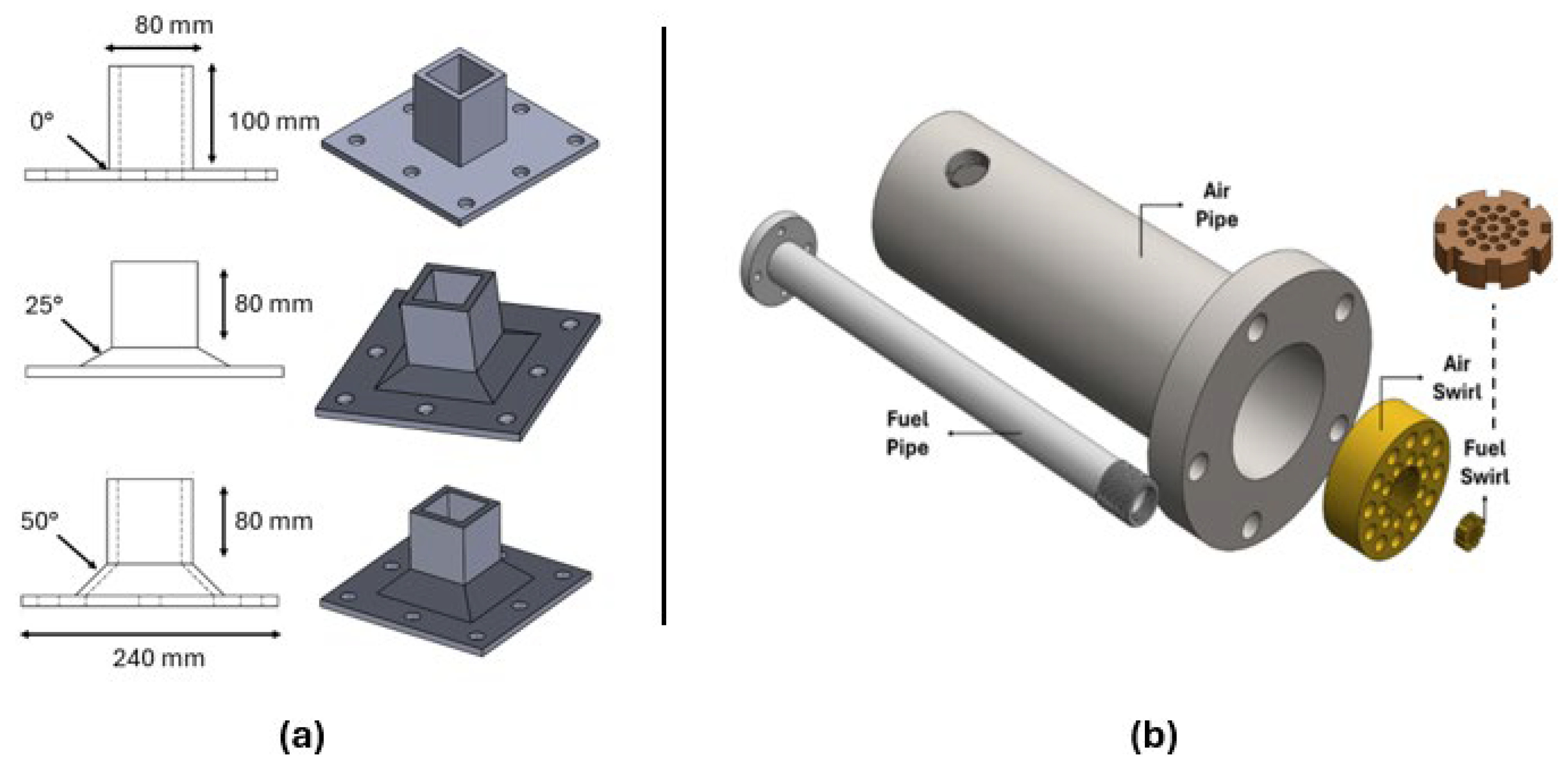
The exhaust nozzle geometry in non-premixed burners plays a crucial role in shaping the flow structure, residence time, and mixing pattern within the combustion zone, and thus directly governs how the flame develops and stabilizes. When the nozzle is set at moderate inclination angles, the interaction between the fuel jet and the surrounding air is intensified, which promotes more effective entrainment, enhances scalar mixing, and supports a more uniformly distributed temperature field throughout the flame. This improved mixing generally leads to more complete oxidation of the fuel and a more stable flame with fewer regions of incomplete combustion or local quenching [
43]. In contrast, very shallow or excessively steep nozzle orientations can either shorten the effective residence time of the reactants in the high-temperature region or over-elongate the flame, which disrupts the balance between mixing and heat release [
44]. Such non-optimal orientations tend to create stronger gradients in velocity and temperature, increase local strain rates, and push parts of the flame closer to extinction limits [
45]. Overall, the orientation of the nozzle has significant effect on how the combustion process organizes itself in space, determining the structure, stability, and completeness of the non-premixed flame [
46].
Despite extensive research on swirl-stabilized combustion, most previous studies have focused on the effects of swirl number, burner configuration, and fuel–air mixing strategies on flame stability and emissions. In contrast, relatively limited attention has been devoted to the role of outlet geometric constraints in shaping the behavior of swirl-diffusion flames. Previous studies have shown that downstream exhaust nozzle geometry can significantly influence the upstream combustor flow field, including the structure and position of recirculation zones, flame shape, temperature distribution, and emissions, by modifying confinement and flow recovery characteristics [
47]. However, the coupled interaction between swirl-induced recirculation and outlet-induced confinement remains insufficiently explored in experimental methane diffusion flame burners, particularly when both air and fuel streams are swirled. Therefore, the present study experimentally investigates how exhaust nozzle inclination affects temperature distribution and emission characteristics in a methane diffusion flame burner operating under co-swirled air and fuel flows. To the authors’ knowledge, no prior study has systematically examined this combined effect under the present burner configuration and operating conditions.
3. Results and Discussion
This section presents the combustion response of the burner in a progressive manner, beginning with the near-field flame behavior and then moving toward the downstream and exhaust regions. First, the flame-core temperature is analyzed to assess local flame structure and stabilization near the burner exit. Next, the downstream axial temperature and flue gas temperature are discussed to evaluate the influence of exhaust nozzle inclination on heat retention and thermal transport within the chamber. The temperature results are then interpreted collectively to identify the dominant governing mechanisms, followed by an analysis of CO2 and CO emissions. Because no direct flow-field diagnostics were performed, the discussion of recirculation, draft, and residence-time effects is based on physically consistent interpretation of the measured temperature and exhaust gas data rather than direct visualization or velocity measurements.
3.1. Flame-Core Temperature
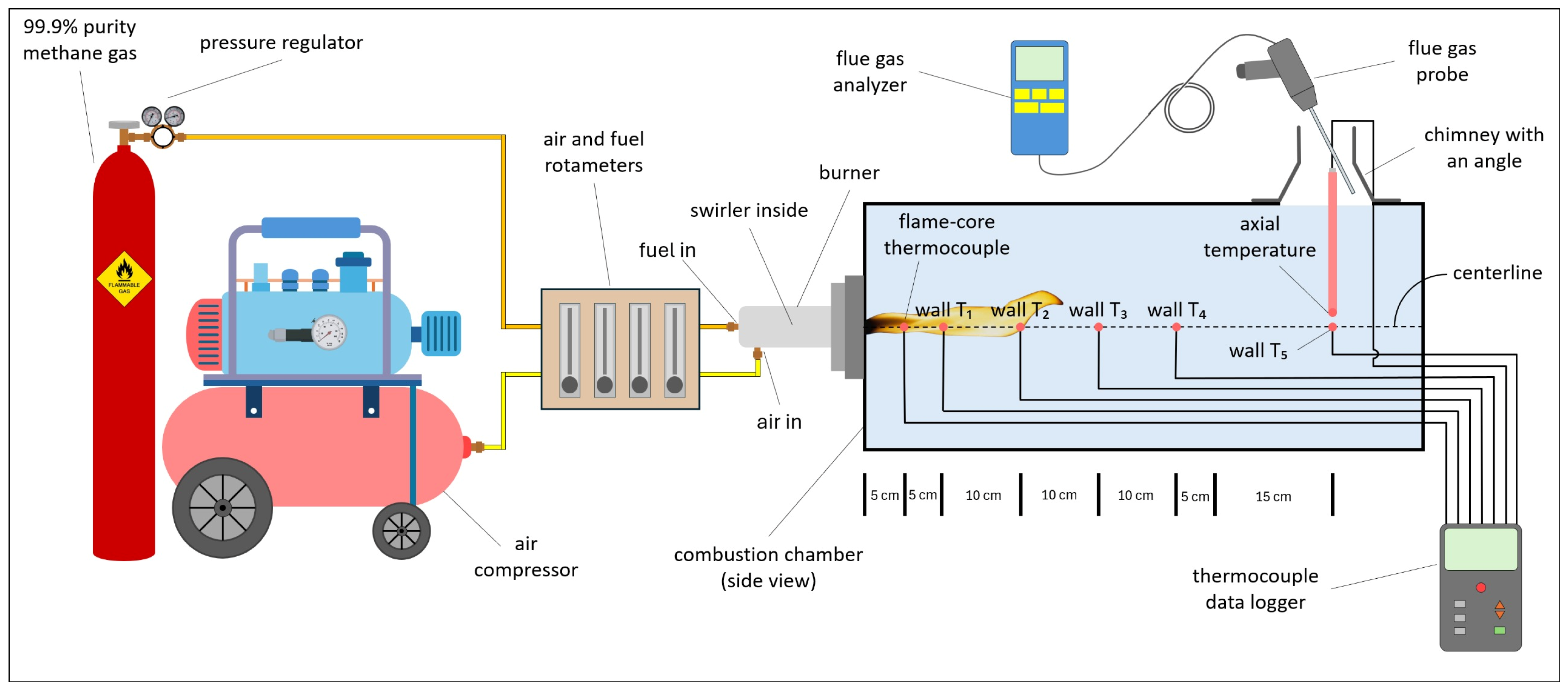
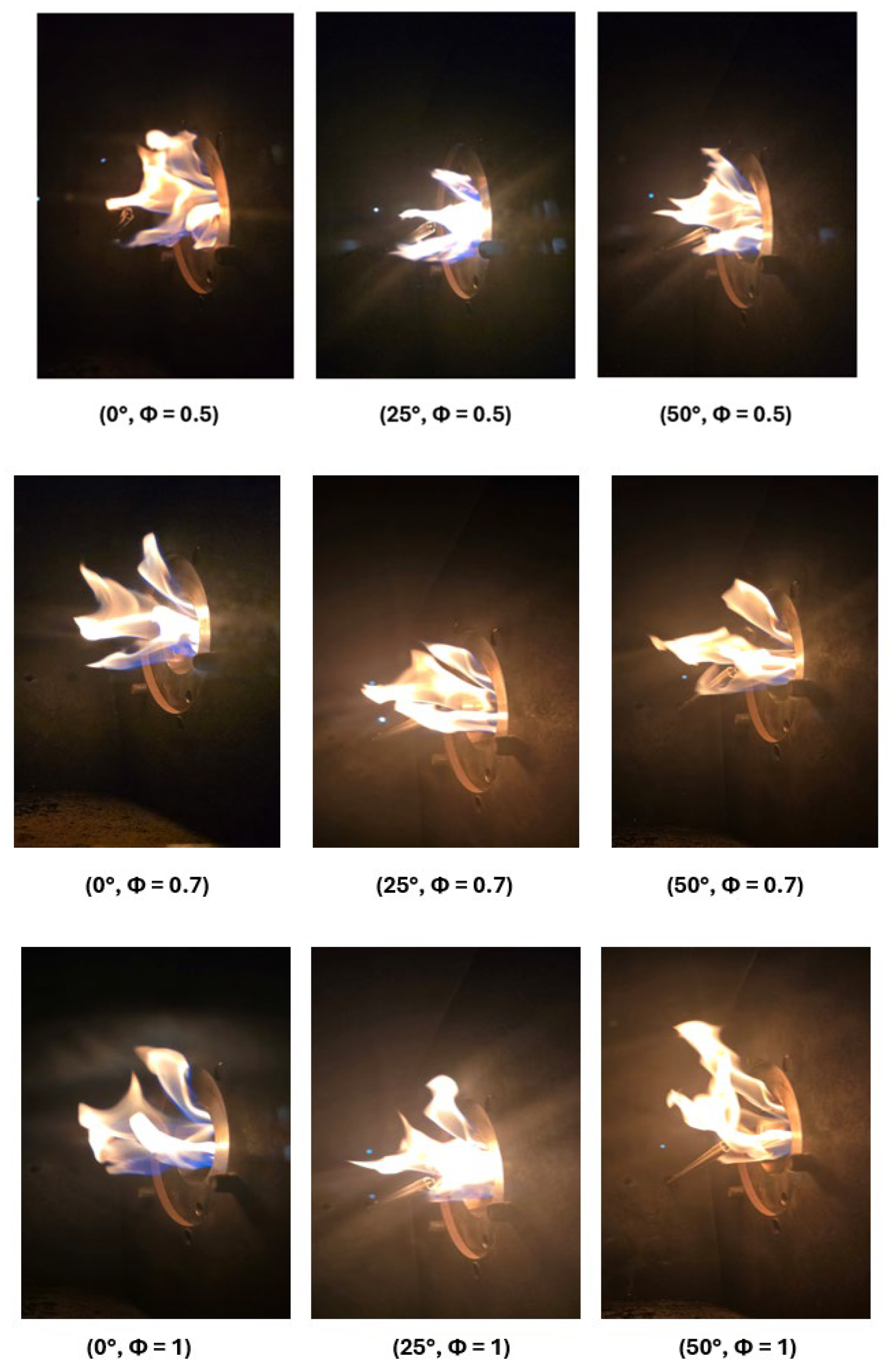
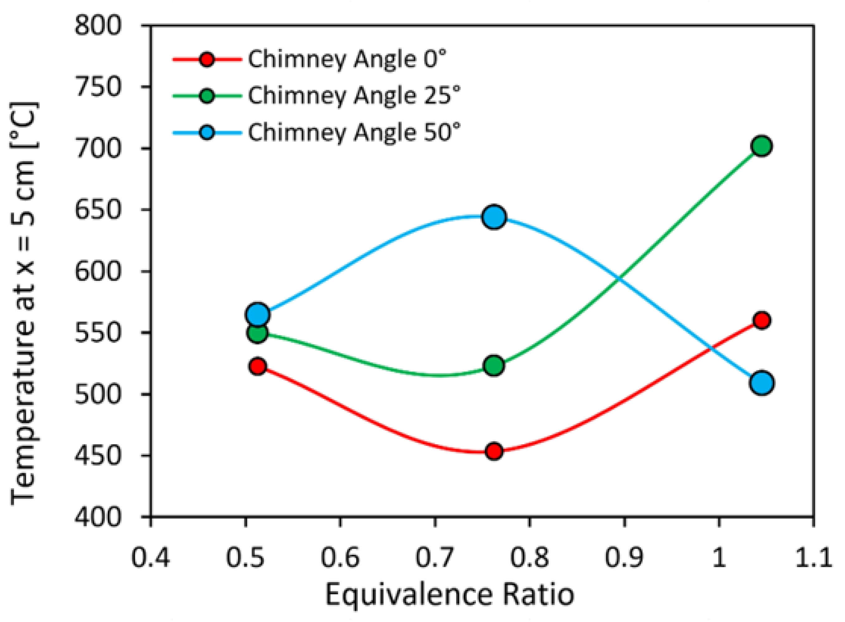
Figure 4 illustrates the variation in the flame-core temperature measured at x = 5 cm downstream of the burner exit as a function of equivalence ratio for three nozzle configurations (0°, 25°, and 50°), at a fixed swirler angle of 30°. The equivalence ratio varied by adjusting the air flow rate while maintaining a constant fuel supply of 3 L/min. This measurement location lies within the near-field flame region and therefore reflects local combustion intensity and flame positioning rather than global thermal performance. As such, the observed temperature trends are governed by the combined effects of local equivalence ratio, mixing quality, thermal dilution, and flame stabilization mechanisms. During the experiments, the flame remained stable for all tested operating conditions. No significant flame lift-off, blow-off, or oscillatory combustion behavior was observed within the investigated equivalence-ratio range.
For the 0° nozzle configuration, corresponding to the absence of inclined nozzle walls, the flame-core temperature exhibits a non-monotonic dependence on equivalence ratio. As the equivalence ratio decreases from Φ ≈ 1.05 to Φ ≈ 0.76, the flame-core temperature decreases from approximately 560 °C to 453 °C. A further reduction in equivalence ratio to Φ ≈ 0.51 results in a partial recovery of the temperature to about 523 °C. The initial temperature decrease can be attributed to the increasing air flow rate, which enhances oxidizer availability but simultaneously introduces significant thermal dilution in the near-burner region. In the absence of nozzle-induced confinement, the flame is free to expand laterally and upward under buoyancy effects, promoting entrainment of cooler surrounding gases and shifting the high-temperature reaction zone away from the centerline measurement location. In addition to dilution effects, changes in air flow rate also modify the momentum of the incoming oxidizer stream, which can influence flame positioning relative to the fixed thermocouple location. Consequently, the measured flame-core temperature decreases despite sustained combustion. At leaner conditions, the apparent temperature recovery at Φ ≈ 0.51 should not be interpreted as an increase in overall flame temperature. Instead, it is more likely associated with a shift in the flame base and high-temperature reaction zone relative to the fixed thermocouple location at x = 5 cm. In swirling diffusion flames, changes in air flow rate can modify the balance between recirculation strength, jet momentum, and buoyancy, thereby altering the local flame structure and the position of the reaction zone. Consequently, the measured temperature may increase locally even though the mixture becomes leaner and thermal dilution is stronger. Overall, for the 0° angle configuration, the flame-core temperature is strongly influenced by flame displacement and dilution rather than by total heat release.
A similar non-monotonic trend is observed for the 25° nozzle configuration, although the absolute temperature levels and sensitivity to equivalence ratio differ markedly. At Φ ≈ 1.05, the flame-core temperature reaches approximately 702 °C, which is substantially higher than that recorded for the 0° configuration. As the equivalence ratio decreases to Φ ≈ 0.76, the temperature drops to around 523 °C, followed by a modest increase to approximately 550 °C at Φ ≈ 0.51. The significantly higher flame-core temperature near stoichiometric conditions indicates that the presence of moderately inclined nozzle walls introduces partial confinement that restricts lateral flame expansion and reduces entrainment of cooler ambient gases. This confinement increases local residence time and helps maintain the flame closer to the centerline thermocouple, thereby elevating the measured temperature. As the air flow rate increases, dilution effects again become dominant, leading to a reduction in flame-core temperature at Φ ≈ 0.76, suggesting that increasing air flow alters the local flame structure and the temperature measured at the fixed centerline location. At leaner conditions, Φ ≈ 0.51, improved mixing and swirl-induced turbulence promote stable combustion near the burner exit, while the nozzle-induced confinement assists in retaining the flame within the measurement region, producing a modest temperature recovery.
In contrast, the 50° nozzle configuration displays a distinct behavior characterized by a clear temperature maximum at an intermediate equivalence ratio. At Φ ≈ 1.05, the flame-core temperature is approximately 509 °C, which is lower than the corresponding values for both the 0° and 25° configurations. As the equivalence ratio decreases to Φ ≈ 0.76, the temperature increases sharply to a peak value of about 644 °C, before decreasing again to approximately 564 °C at Φ ≈ 0.51. At higher nozzle angles, the exhaust opening becomes significantly narrower, introducing increased flow restriction and backpressure within the combustion chamber. Near stoichiometric conditions, this strong confinement can alter the flame structure and promote upward deflection of the flame due to buoyancy, displacing the high-temperature reaction zone away from the centerline location at x = 5 cm. As a result, the measured flame-core temperature is reduced despite adequate fuel availability. At intermediate equivalence ratio, an optimal balance is achieved between oxidizer supply, mixing intensity, and nozzle-induced recirculation, yielding the highest flame-core temperature for this configuration. At very lean conditions, further increases in air flow intensify thermal dilution and heat losses, leading to a reduction in flame-core temperature even though confinement remains strong.
Taken together, the results in
Figure 4 demonstrate that the flame-core temperature at x = 5 cm is governed by a complex interplay between air-induced dilution, combustion efficiency, flame positioning, and geometric confinement imposed by the nozzle. Variations in nozzle angle modify the local flow field and recirculation patterns, thereby influencing whether the flame intersects the measurement location and how effectively heat is retained in the near-field region. Consequently, changes in flame-core temperature should be interpreted as indicators of local flame structure and stabilization behavior rather than as direct measures of overall combustion performance.
3.2. Downstream Axial Temperature
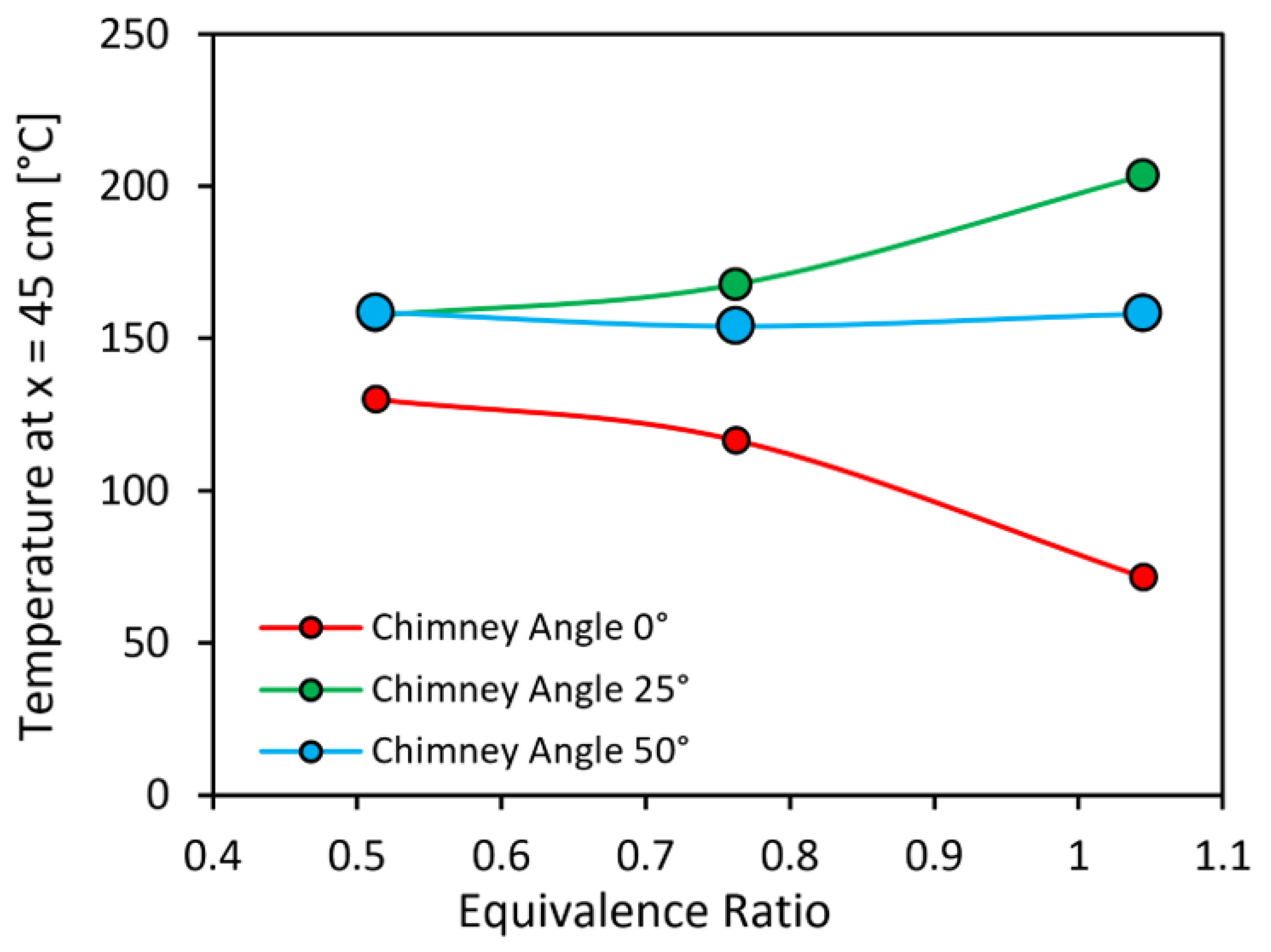
Figure 5 presents the variation in the axial gas temperature measured at x = 45 cm downstream of the burner exit as a function of equivalence ratio for three nozzle configurations (0°, 25°, and 50°), at a fixed swirler angle of 30° and a methane fuel flow rate of 3 L/min. This measurement location lies well downstream of the primary reaction zone and represents a post-flame, developing exhaust region within the combustion chamber. Consequently, the measured temperature reflects the combined influence of heat release completeness, residence time, dilution by excess air, and heat losses to the chamber walls, rather than local flame intensity.
For the 0° nozzle configuration, the axial temperature exhibits a monotonic decrease as the equivalence ratio increases from lean to near-stoichiometric conditions. At Φ ≈ 0.51, the axial temperature reaches approximately 130 °C, decreases to about 117 °C at Φ ≈ 0.76, and drops further to approximately 72 °C at Φ ≈ 1.05. This trend indicates that, in the absence of nozzle-induced confinement, increasing equivalence ratio does not translate into higher downstream gas temperatures. Instead, as the air flow rate is reduced, the axial temperature decreases, indicating that downstream temperatures are governed by dilution and residence time rather than combustion completeness. This behavior can be attributed to a reduction in bulk gas momentum and residence time within the chamber. With no nozzle walls to restrict the exhaust, combustion products escape readily through the open outlet, limiting the time available for thermal energy to accumulate in the downstream region. Additionally, buoyancy-driven upward motion promotes early diversion of hot gases away from the centerline measurement location, further reducing the measured axial temperature at x = 45 cm. Under lean conditions, the higher air flow rate enhances convective transport of hot gases downstream and increases mixing, resulting in a comparatively higher axial temperature despite the presence of thermal dilution. In this study, the term buoyancy-driven draft refers to the natural upward motion of hot combustion gases generated by density differences between the hot combustion products and the surrounding ambient air inside the chamber. This draft mechanism influences the transport of combustion products and therefore affects temperature distribution and emission characteristics within the combustion chamber.
In contrast, the 25° nozzle configuration exhibits a markedly different trend. The axial temperature is highest at near-stoichiometric conditions, reaching approximately 204 °C at Φ ≈ 1.05, decreases to around 168 °C at Φ ≈ 0.76, and further decreases to approximately 157 °C at Φ ≈ 0.51. Relative to the 0° angle configuration, the axial temperature is elevated across the entire equivalence-ratio range, with the difference becoming most pronounced at near-stoichiometric operation. The introduction of moderately inclined nozzle walls imposes partial flow restriction at the exhaust, increasing residence time and limiting the rapid escape of hot combustion products. This confinement promotes accumulation of thermal energy in the downstream region and enhances heat retention within the chamber. At near-stoichiometric conditions, where chemical heat release is maximized, these effects combine to produce the highest axial temperature observed for 25° nozzle. As the equivalence ratio decreases and air flow increases, thermal dilution and enhanced convective heat transfer to the chamber walls reduce the axial temperature, although the values remain substantially higher than those observed without a nozzle. Compared with the 0° angle configuration, the 25° angle nozzle therefore shifts the controlling mechanism from rapid exhaust and buoyancy-dominated transport to residence-time-controlled heat retention.
The 50° angle nozzle configuration displays a comparatively weak dependence of axial temperature on equivalence ratio. The measured temperature remains nearly constant across the tested conditions. This behavior suggests that the strong geometric restriction imposed by the steep nozzle walls dominates the downstream thermal field, effectively decoupling the axial temperature from variations in equivalence ratio within the range investigated. The narrow exhaust opening substantially increases flow resistance and promotes sustained recirculation of combustion products within the chamber, leading to a quasi-uniform thermal environment in the downstream region. Under these conditions, changes in air flow rate primarily alter the balance between dilution and heat loss rather than the overall residence time, resulting in only minor variations in axial temperature. Unlike the 25° configuration, however, the strong restriction does not yield a pronounced temperature increase at near-stoichiometric conditions, suggesting that excessive confinement may limit effective transport of hot gases toward the measurement location or enhance heat losses through prolonged wall contact.
Overall, the results in
Figure 5 demonstrate that the axial temperature at x = 45 cm is governed by a balance between air-flow-induced dilution, residence time, buoyancy-driven transport, and nozzle-induced confinement. While increased air flow enhances dilution, it also increases gas momentum and convective transport, which can elevate downstream temperatures when confinement is weak. Conversely, reduced air flow increases the chemical energy content of the mixture but may lead to lower axial temperatures if residence time and confinement are insufficient. The presence and geometry of the nozzle therefore play a critical role in determining whether combustion efficiency or thermal retention dominates the downstream temperature field.
3.3. Flue Gas Temperature
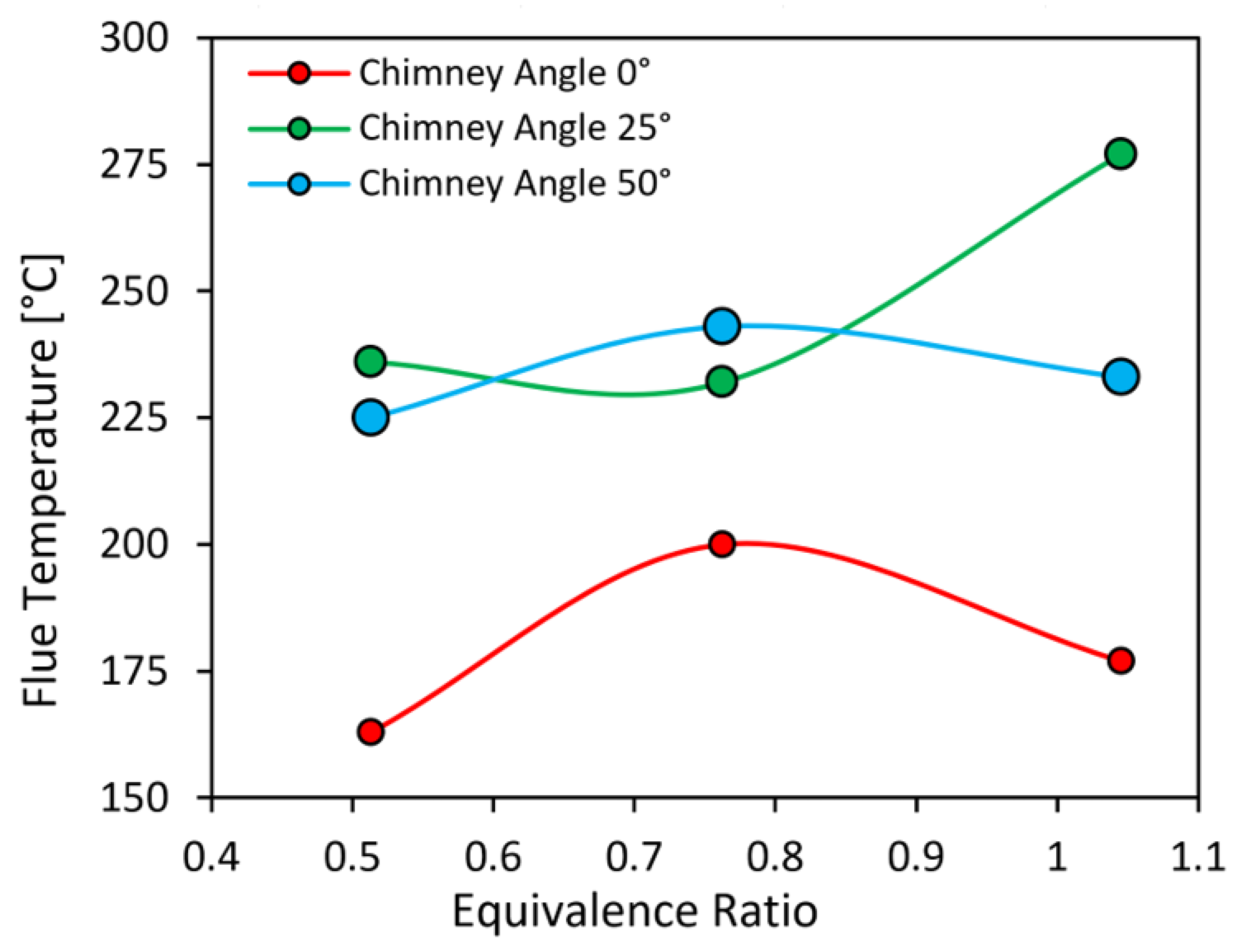
Figure 6 shows the variation in the flue gas temperature measured inside the nozzle as a function of equivalence ratio for three nozzle configurations (0°, 25°, and 50°), at a fixed swirler angle of 30° and a methane fuel flow rate of 3 L/min. The flue temperature represents a bulk exhaust metric and reflects the integrated outcome of combustion heat release, dilution by excess air, residence time within the chamber, and heat losses occurring before the gases exit through the nozzle. Unlike the flame-core and axial measurements, this location captures the thermal state of the gases after they have traversed the combustion chamber and entered the exhaust pathway.
For the 0° nozzle configuration, the flue temperature exhibits a non-monotonic dependence on equivalence ratio. As the equivalence ratio decreases from Φ ≈ 1.05 to Φ ≈ 0.76, the flue temperature increases from approximately 177 °C to 200 °C, followed by a decrease to about 163 °C as the equivalence ratio is further reduced to Φ ≈ 0.51. The initial temperature increase with decreasing equivalence ratio can be attributed to enhanced convective transport of hot gases toward the exhaust under higher air flow rates. In the absence of nozzle walls, the exhaust opening is unrestricted, and the flue temperature is strongly influenced by the momentum of the rising gases rather than by confinement-driven heat retention. At intermediate air flow rates, this increased momentum promotes efficient transport of hot combustion products into the flue, resulting in the observed temperature peak. At leaner conditions, however, thermal dilution becomes dominant, as the large excess air volume absorbs a greater fraction of the released heat, reducing the bulk exhaust temperature despite sustained combustion. The lack of geometric confinement also limits residence time and allows hot gases to mix readily with cooler surroundings, further contributing to the temperature decline.
The 25° nozzle configuration exhibits a weakly non-monotonic dependence of flue temperature on equivalence ratio, characterized by a shallow minimum at the intermediate condition and a pronounced increase near stoichiometric operation. The flue temperature decreases slightly from approximately 236 °C at Φ ≈ 0.51 to about 232 °C at Φ ≈ 0.76, before increasing sharply to approximately 277 °C at Φ ≈ 1.05. The small reduction between Φ ≈ 0.51 and Φ ≈ 0.76 suggests a transitional regime in which the competing effects of air-flow-induced dilution and nozzle-induced heat retention are of comparable magnitude. At Φ ≈ 0.76, the reduction in air flow rate relative to the lean case lowers convective transport of hot gases toward the nozzle while thermal dilution remains non-negligible, resulting in a modest decrease in the measured flue temperature. As the equivalence ratio increases further toward near-stoichiometric conditions, the combined effects of reduced dilution, increased chemical heat release, and enhanced residence time due to nozzle confinement dominate, producing a substantial rise in flue temperature. Compared with the 0° configuration, the 25° nozzle shifts the dominant balance from momentum-controlled exhaust transport toward confinement-controlled heat retention, yielding a stronger overall sensitivity of flue temperature to equivalence ratio.
The 50° nozzle configuration exhibits a comparatively weak and non-monotonic dependence of flue temperature on equivalence ratio. The flue temperature increases from approximately 225 °C at Φ ≈ 0.51 to a maximum of about 243 °C at Φ ≈ 0.76, before decreasing slightly to approximately 233 °C at Φ ≈ 1.05. The strong geometric restriction imposed by the steep nozzle walls significantly limits entrainment of cooler air and promotes sustained recirculation of combustion products within the chamber. As a result, the flue temperature remains relatively high and less sensitive to changes in equivalence ratio compared with the 0° configuration. However, unlike the 25° nozzle, the increased restriction does not yield a pronounced temperature increase at near-stoichiometric conditions. This suggests that excessive confinement may enhance wall heat losses or alter the flow distribution entering the nozzle, reducing the net thermal energy carried into the flue despite favorable combustion conditions. At intermediate equivalence ratio, the balance between dilution, residence time, and confinement appears most favorable, producing the highest flue temperature for this configuration. This behavior suggests that stronger confinement can increase the contact between hot combustion gases and the chamber walls, which enhances heat transfer before the gases exit through the nozzle and may therefore reduce the measured flue gas temperature. Because the exhaust mass flow rate was not measured, the present study does not calculate a formal thermal-efficiency metric; instead, the outlet configurations are compared using flue gas temperature response, downstream thermal behavior, and emission characteristics.
In summary, the results in
Figure 6 indicate that the flue gas temperature is governed by a balance between air-flow-induced dilution, combustion efficiency, exhaust momentum, and nozzle-induced confinement. While increased air flow promotes dilution, it also enhances convective transport of hot gases toward the exhaust, which can elevate flue temperatures when confinement is weak. Conversely, reduced air flow increases the chemical energy content of the mixture but may lead to lower flue temperatures if excessive confinement or wall heat losses limit effective heat transfer to the exhaust stream. The nozzle geometry therefore plays a critical role in determining whether dilution, residence time, or heat retention dominates the flue-temperature response across the equivalence-ratio range.
3.4. Spatial Variation in Temperature and Governing Mechanisms
It should be emphasized that the present interpretation of recirculation and draft behavior is qualitative. Since no direct flow-field diagnostics or computational fluid dynamic (CFD) simulations were performed, the proposed mechanisms are inferred from the measured temperature distributions and exhaust gas characteristics and should be understood as physically consistent interpretations rather than direct visualization of the internal flow structure. Although direct flow visualization techniques were not used in this study, the influence of nozzle inclination on flow recirculation can be inferred from the measured temperature distributions and emission trends. Variations in nozzle geometry modify confinement and draft behavior, which influence the transport and residence time of combustion gases within the chamber. Considered together, the flame-core, downstream axial, and flue gas temperature measurements reveal a systematic shift in the dominant thermal control mechanisms along the length of the combustion chamber. In the near-field region at x = 5 cm (
Figure 4), the measured temperature is primarily governed by local flame structure, mixing quality, and the relative position of the reaction zone with respect to the fixed measurement location. Variations in nozzle angle influence this region indirectly through confinement-induced changes in flame expansion and buoyancy-driven deflection, resulting in non-monotonic trends that reflect flame relocation rather than global heat release. Further downstream at x = 45 cm (
Figure 5), the temperature response becomes increasingly controlled by residence time, bulk gas momentum, and nozzle-induced confinement. In this post-flame region, the presence of inclined nozzle walls suppresses rapid exhaust of hot gases and enhances heat retention within the chamber, leading to elevated axial temperatures even when flame-core temperatures decrease. Finally, the flue gas temperature (
Figure 6) represents the integrated thermal outcome of upstream combustion, dilution, and heat losses prior to exhaust. At this location, the balance between air-flow-induced dilution, exhaust momentum, and nozzle confinement determines how effectively the chemical energy released during combustion is transported into the flue. The contrasting trends observed across
Figure 4,
Figure 5 and
Figure 6 therefore highlight that increasing nozzle confinement progressively shifts the governing mechanism from local flame positioning to residence-time-controlled heat retention and, ultimately, to exhaust heat transfer efficiency.
3.5. Emissions
In the present experiments, exhaust gas measurements were limited to CO
2 and CO, and NO
x was not measured. Accordingly, the emissions discussion focuses on oxidation completeness and carbon-conversion behavior, while any implications for NO
x are discussed only qualitatively in light of the combustion literature on recirculation, temperature field modification, and flame stabilization.
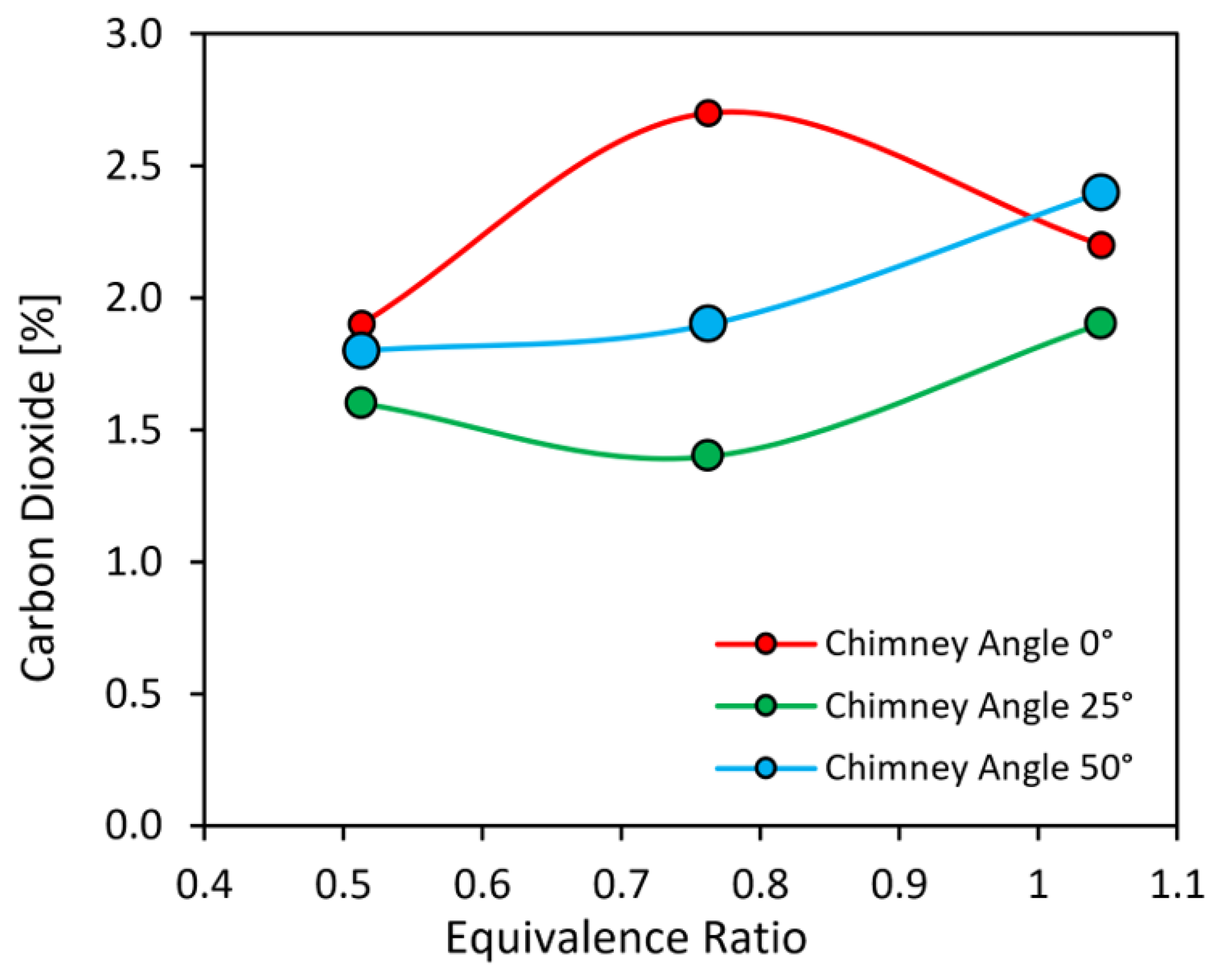
Figure 7 illustrates a comparison of CO
2 as the dependent variable with respect to the equivalence ratio as the independent variable in this study. The comparison is done under constant swirl angle (30°) and fuel rate (3 L/min), whereas the nozzle angles and air flow rates are changed during the experiments.
The general observed trends of
Figure 7 indicates that CO
2 concentrations remain relatively low (approximately 1.5–3.2%) for all nozzle angles, with modest variations as the equivalence ratio varies from lean (0.5) to stoichiometric (1.0), consistent with reports that CO
2 emissions in gaseous flames change only moderately over this range compared with more sensitive pollutants such as CO [
50]. At
, CO
2 is highest for the 50° nozzle, slightly lower for 0°, and lowest for 25°, which accords with studies indicating that near-stoichiometric conditions maximize complete carbon oxidation and that configurations enhancing residence time and mixing (e.g., inclined or swirled flows) increase CO
2 at the expense of CO and unburned hydrocarbons [
51]. The superior performance of the 50° nozzle suggests a stronger buoyancy-driven draft and more effective post-flame mixing, promoting further oxidation of CO before exhaust, whereas the 25° case likely creates less favorable recirculation and temperature fields, as observed in intermediate swirl and nozzle angles that yield weaker hot zones and slightly reduced CO
2. At
, the vertical (0°) nozzle exhibits the highest CO
2, while the 50° and 25° configurations give lower values clustered around 1.4–2.6%, reflecting the greater sensitivity of lean flames to flow organization; here, the straight nozzle probably maintains a more symmetric and stable core, providing longer residence in a sufficiently hot region for CO oxidation, whereas inclined nozzles may accelerate the flow or redistribute temperature, shortening effective post-flame residence time and thereby reducing CO
2, in agreement with observations from nozzle-assisted biomass stoves and confined burners. At the most lean condition,
, CO
2 levels for all angles converge near 1.6–1.9%, implying that under strongly lean, low-temperature operation the global equivalence ratio dominates carbon oxidation and geometric effects become secondary, a behavior consistent with lean premixed and inverse diffusion flame studies that report flattened CO
2 trends with geometry and a stronger influence on stability limits than on CO
2 magnitude [
52]. The slightly higher CO
2 for 0° and 50° compared with 25° at this equivalence ratio may still denote marginal advantages in sustaining a coherent recirculation zone or adequate draft, which can preserve a thinner yet hotter reaction region and thus modestly enhance CO oxidation even in very lean regimes, as documented for optimized swirl and nozzle configurations in the literature. The exhaust flow rate was not measured in this study. The gas analyzer reports CO
2 concentration (vol%) in the sampled flue gas, not the total CO
2 mass flow. Therefore,
Figure 6 presents concentration levels rather than emission rates. In practical combustion systems, the CO
2 concentration does not always decrease strictly linearly with equivalence ratio because it is influenced by excess-air dilution, mixing conditions inside the chamber, and draft-induced entrainment in the nozzle. A clarification has been added to the manuscript.
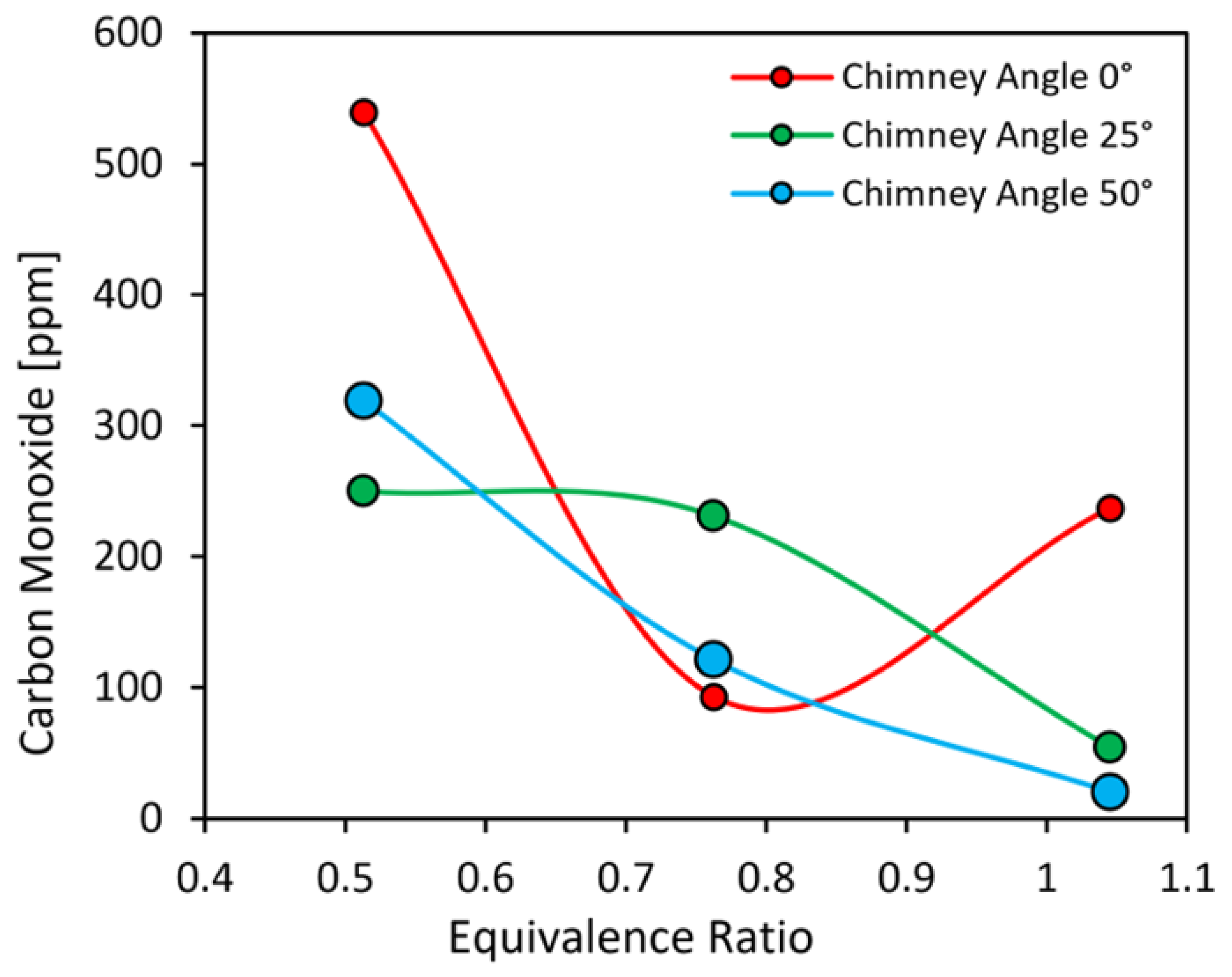
Figure 8 presents CO concentrations as a function of equivalence ratio for three nozzle inclinations at a fixed fuel flow rate of 3 L/min, and the trends are broadly consistent with established combustion literature on nozzle-assisted and swirled gaseous flames, where improved mixing and longer residence time promote the oxidation of CO to CO
2 [
53].
At
, CO is lowest for the 50° nozzle (near zero), slightly higher for 25°, and highest for the 0° configuration, suggesting that a larger inclination angle enhances buoyancy-driven draft and post-flame entrainment, thereby increasing local temperature and residence time and allowing more complete CO oxidation, as reported for optimized nozzle and swirl vane geometries. At the intermediate equivalence ratio
, the 0° nozzle still exhibits higher CO than the inclined cases, whereas the 25° and 50° configurations show reduced and comparable CO levels; this behavior is consistent with findings that, under lean conditions, modest tilting or swirling of the flow improves air–fuel mixing and mitigates localized fuel-rich pockets that otherwise generate CO in vertical, weakly mixed flows [
54]. At the most fuel-lean condition
, all three configurations display elevated CO relative to stoichiometric operation, but the 0° nozzle again produces the highest CO, followed by 25°, while 50° gives the lowest value, which aligns with reports that very lean flames suffer from reduced reaction rates and are more prone to incomplete oxidation; in such regimes, geometries that maintain a strong recirculation zone and sufficient draft—such as the more inclined nozzle—can partially counteract these limitations and suppress CO, whereas weaker mixing in the vertical or mildly inclined arrangements allows more CO to escape unoxidized [
55].
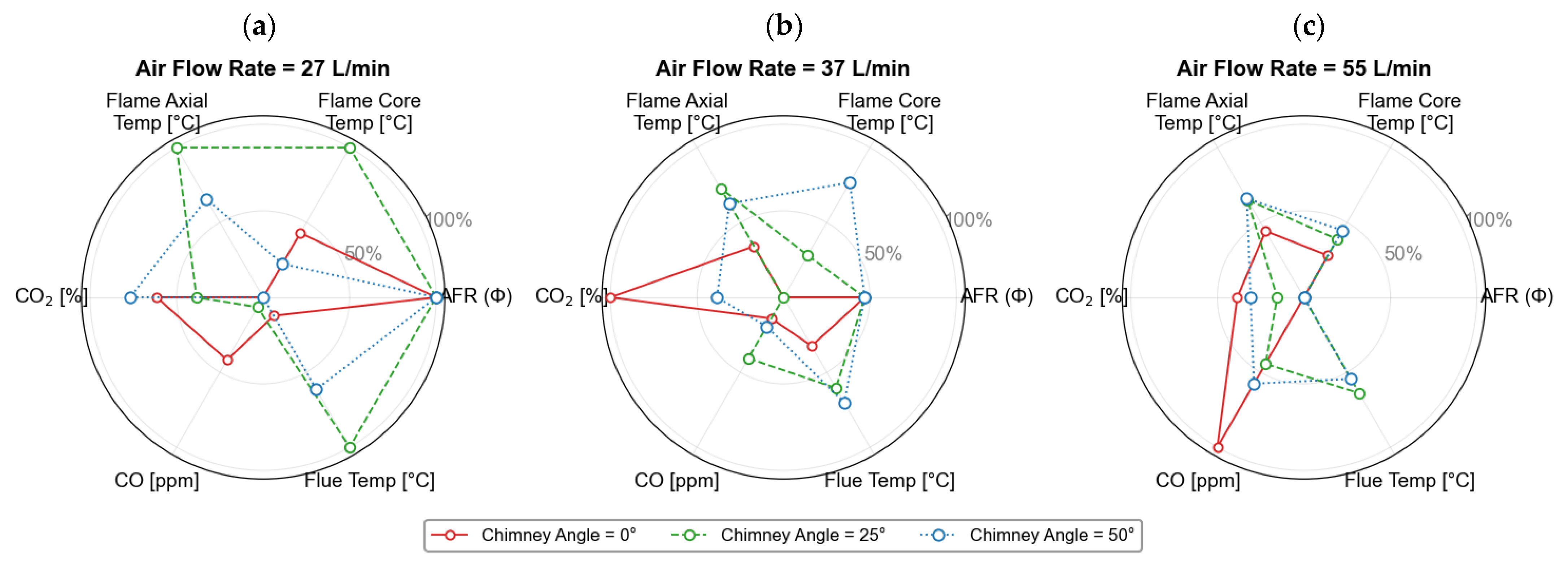
Figure 9 provides a consolidated, multi-parameter comparison of burner performance using an eight-axis spider representation, in which equivalence ratio (Φ), air flow rate, nozzle angle, flame-core temperature, downstream axial temperature, flue temperature, CO, and CO
2 are treated as simultaneous performance axes. By normalizing each variable, the figure enables qualitative assessment of relative trends across operating conditions that would otherwise be difficult to reconcile due to differing physical units and spatial measurement locations. The three subplots correspond to air flow rates of 27, 37, and 55 L/min, allowing the influence of nozzle inclination to be examined under progressively leaner, higher-momentum conditions. At the lowest air flow rate (
Figure 9a), the 25° nozzle exhibits the most expanded thermal envelope, with elevated flame-core, axial, and flue temperatures, reflecting enhanced residence time and heat retention under moderate confinement. In contrast, the 0° configuration shows reduced downstream and exhaust temperatures despite comparable flame-core behavior, indicating that rapid exhaust and buoyancy-driven diversion limit thermal accumulation when confinement is absent.
As the air flow rate increases to 37 and 55 L/min (
Figure 9b,c), the spider plots highlight a systematic shift in the dominant controlling mechanisms. Higher air flow enhances dilution and convective transport, compressing the thermal axes while amplifying differences in emission behavior. Under these conditions, the 50° nozzle consistently shows suppressed CO levels and relatively stable axial and flue temperatures, indicating stronger draft and more effective post-flame oxidation enabled by sustained recirculation, even as peak temperatures are moderated by confinement-induced heat losses. The 25° configuration maintains a balanced response across thermal and emission metrics, whereas the 0° nozzle exhibits the greatest sensitivity to air flow rate, with diminished thermal performance and elevated CO at lean conditions. Overall,
Figure 9 synthesizes the individual temperature and emission trends presented earlier into a unified framework, demonstrating that nozzle geometry governs the trade-off between dilution, residence time, heat retention, and post-flame oxidation, and that optimal burner performance emerges from a coordinated balance rather than from maximizing any single parameter in isolation.
3.6. Scaling Considerations for Industrial Burners
This section is intended as a qualitative outlook based on established burner-scaling principles and is not presented as a direct demonstration of dynamic similarity for the current apparatus. Although the present investigation was performed on a laboratory-scale burner operating at 1.8 kW, laboratory experiments are commonly used in the development and optimization of industrial combustion systems. In many cases, prototype burners are first tested at reduced scales and then extrapolated to larger thermal inputs using established scaling principles. Studies on burner scaling indicate that maintaining strict similarity for all dimensionless parameters, such as the Reynolds, Froude, and Damköhler numbers, is generally not feasible when increasing the burner thermal input. Consequently, industrial burner development typically relies on partial scaling approaches, where only selected similarity parameters are preserved during scale-up [
56].
Among the commonly applied scaling strategies, constant velocity scaling and constant residence-time scaling are frequently used to maintain similar mixing behavior and characteristic combustion time scales when increasing burner capacity [
56]. In the constant velocity approach, the inlet flow velocity is preserved while the burner diameter is adjusted according to the required thermal input, thereby maintaining similar aerodynamic flow structures and mixing characteristics.
Large experimental investigations such as the international flame research foundation (IFRF) “Scaling 400” project have shown that maintaining geometrical similarity and the fuel-to-air momentum ratio is essential for preserving the overall flow pattern of turbulent flames when scaling burners from laboratory systems to industrial furnaces [
55,
56]. Furthermore, studies of turbulent jet flames indicate that when the Reynolds and Froude numbers remain sufficiently large, the overall flame structure and mixing characteristics tend to remain similar across different burner scales [
55].
Based on these scaling principles, the qualitative trends observed in the present study—particularly the influence of nozzle angle on draft strength, gas residence time, and post-flame oxidation—are expected to remain relevant for larger diffusion flame burners operating under dynamically similar conditions. Nevertheless, quantitative values of temperature and emissions may vary at industrial scales due to differences in furnace confinement, heat extraction, and large-scale flow recirculation. Therefore, further validation at pilot or semi-industrial scales would be beneficial to confirm the applicability of the proposed configuration to industrial combustion systems. Accordingly, the industrial relevance discussed here should be interpreted as a scaling-informed perspective rather than a validated extrapolation of the present laboratory measurements.
4. Conclusions
The effect of nozzle inclination on the combustion characteristics of a swirled methane diffusion flame burner was investigated under different equivalence ratios while maintaining constant swirl angle, fuel flow rate, and thermal load. The results demonstrate that nozzle inclination plays a significant role in shaping the thermal field and emission characteristics of the burner. At x = 5 cm, the 25° nozzle produced the highest flame-core temperature near stoichiometric conditions, reaching about 702 °C, compared with about 560 °C for the 0° nozzle and 509 °C for the 50° nozzle. This indicates that a moderate nozzle inclination enhances local heat concentration and flame stabilization more effectively than either the straight or highly inclined configuration.
The downstream thermal response was also strongly affected by nozzle geometry. The 25° nozzle provided the highest axial and flue gas temperatures near Φ ≈ 1.0, reaching about 204 °C at x = 45 cm and 277 °C in the flue, whereas the corresponding values for the 0° nozzle were about 72 °C and 177 °C. In contrast, the 50° nozzle produced a more uniform downstream temperature distribution, with axial temperatures remaining nearly constant in the range of about 150–160 °C over the tested equivalence-ratio range. This behavior suggests that increasing nozzle inclination promotes stronger dilution and broader thermal spreading, while a moderate inclination offers a more favorable balance between confinement and heat retention.
The emission results further confirm the influence of nozzle inclination on burner performance. The 50° nozzle consistently produced the lowest CO emissions and reduced CO to nearly zero near stoichiometric operation, reflecting more complete post-flame oxidation and better mixing of combustible species with air. Meanwhile, CO2 concentrations remained within a relatively narrow range of about 1.5–3.2% for all nozzle angles, indicating that nozzle geometry had only a limited effect on overall carbon conversion compared with its more pronounced influence on CO formation and temperature distribution.
Overall, the results confirm that modest geometric modification of the exhaust nozzle, when combined with fixed swirl, can significantly improve the thermal response and reduce CO emissions in swirled methane diffusion burners without substantially affecting CO2 levels. Among the tested cases, the 25° nozzle achieved the strongest thermal performance, while the 50° nozzle showed the best emission behavior. These findings highlight the importance of coordinated burner and exhaust design in optimizing the performance of practical diffusion flame systems.