Heat Transfer and Pressure Drop in a Shell-and-Tube Heat Exchanger with Segmental Baffles

 , , , , and
Abstract
1. Introduction
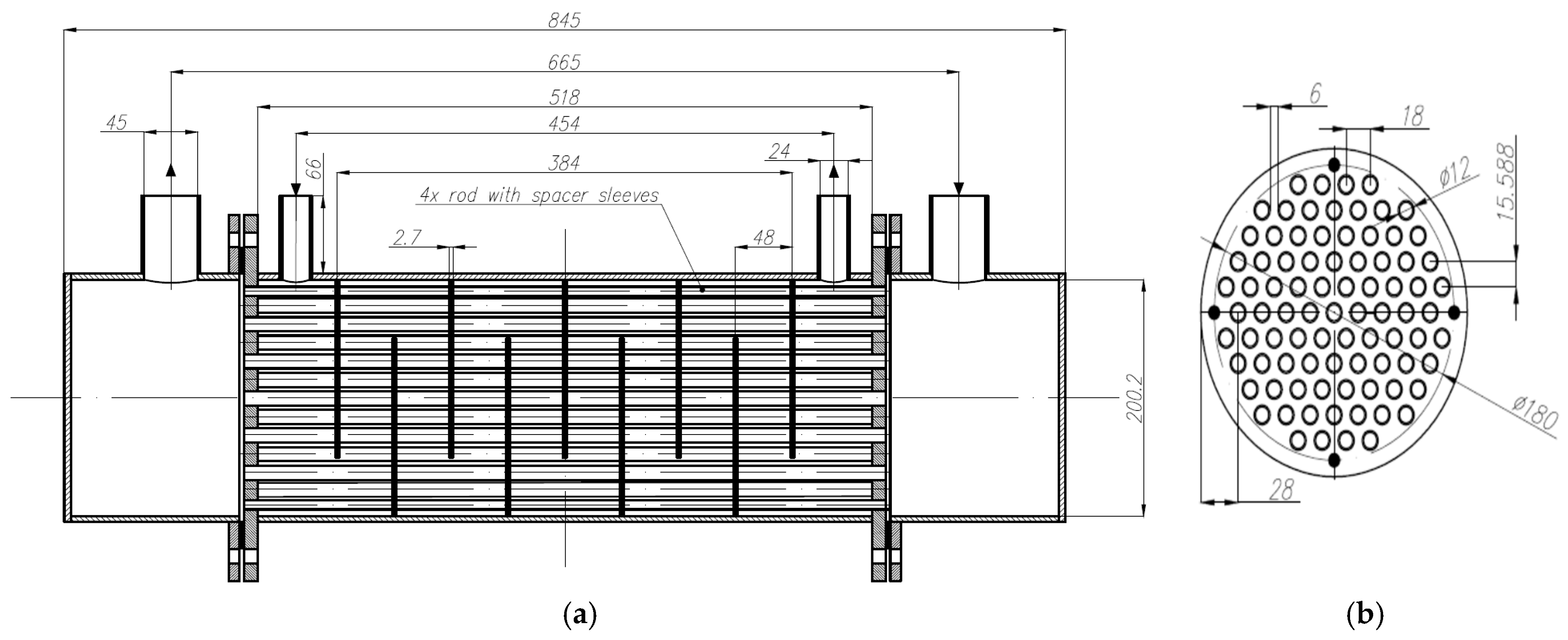
2. Tested Shell-and-Tube Heat Exchanger
3. Materials and Methods
3.1. The Bell–Delaware Extended Model
3.2. The VDI Model
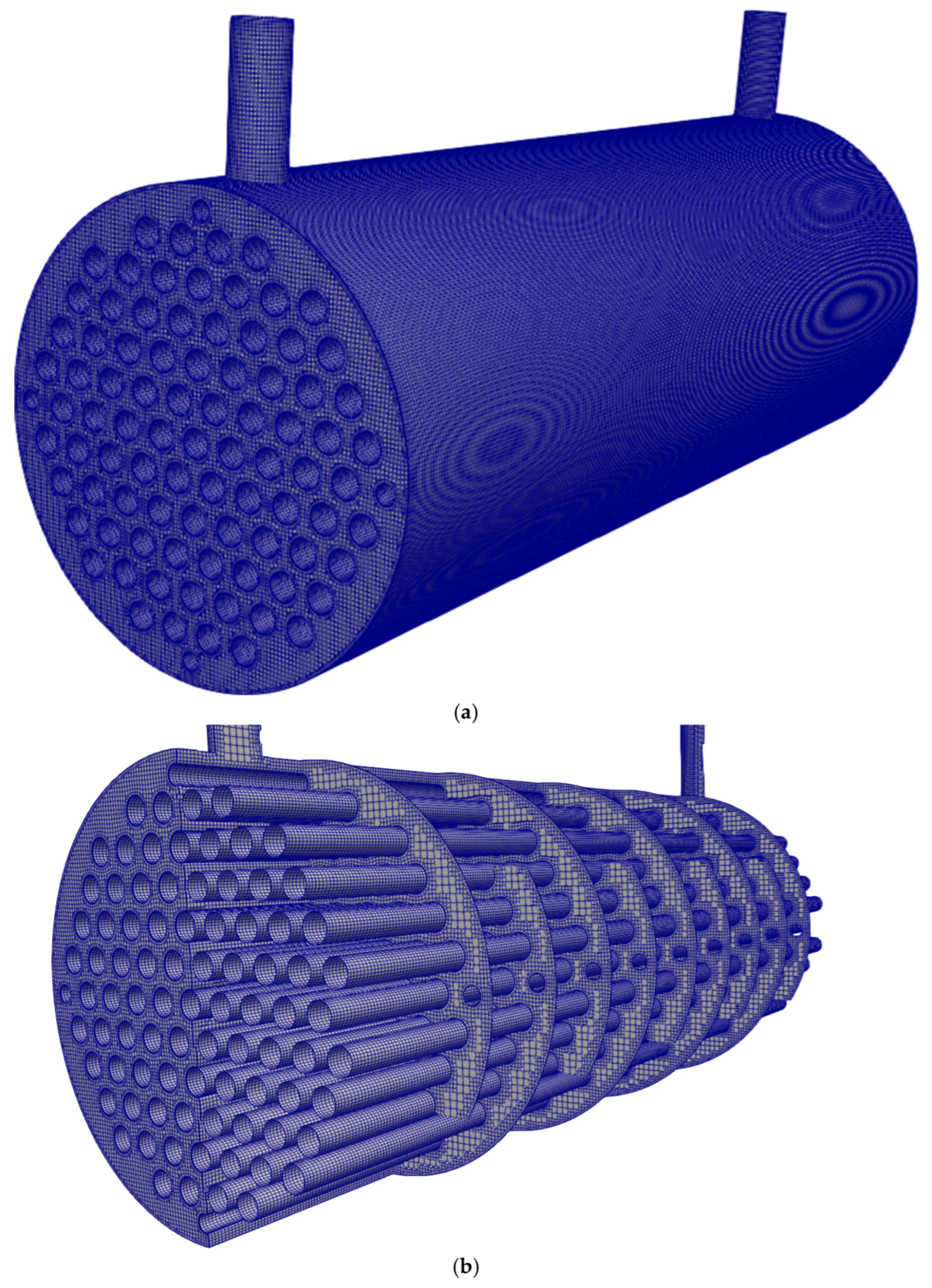
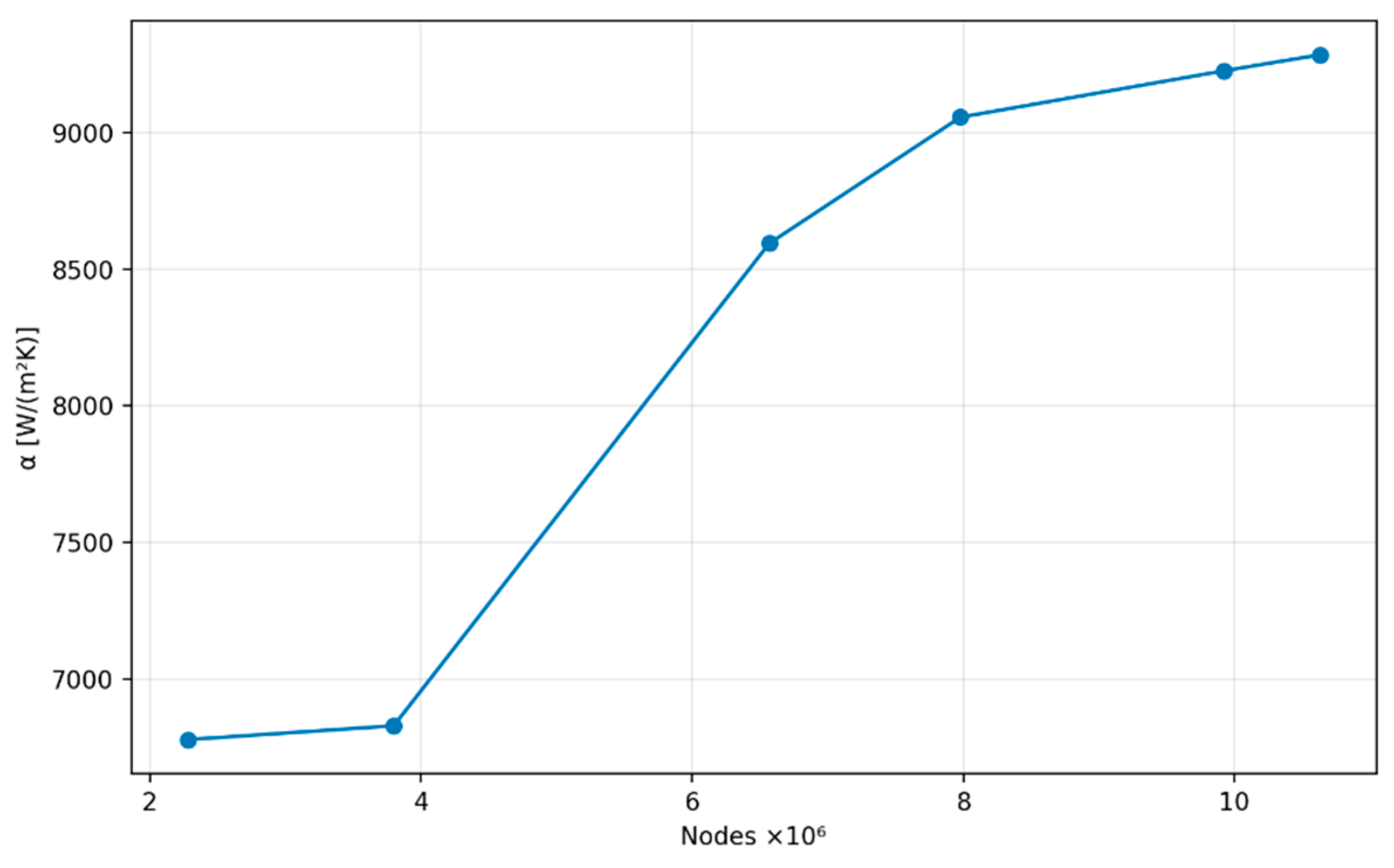
3.3. Open Foam Formulation
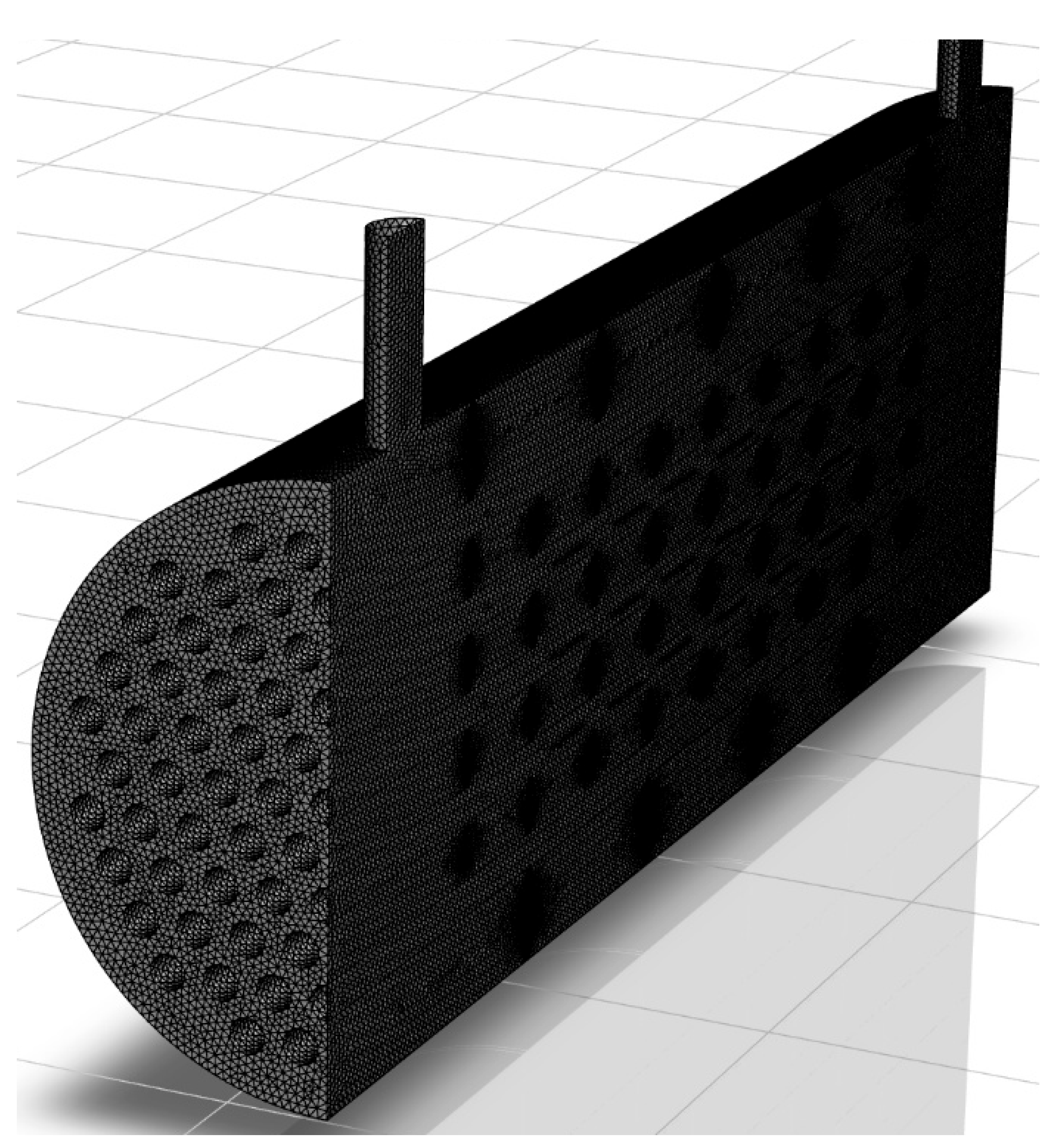
3.4. Ansys Fluent Formulation
3.5. Aspen Exchanger Design and Rating
3.6. Properties of the Tested Fluids
- -
- Dynamic viscosity
- -
- Thermal conductivity
- -
- Density
- -
- Specific heat
- -
- Prandtl number
4. Results
4.1. A Quasi-Ideal Heat Exchanger
4.2. Heat Exchanger with Clearances
5. Conclusions
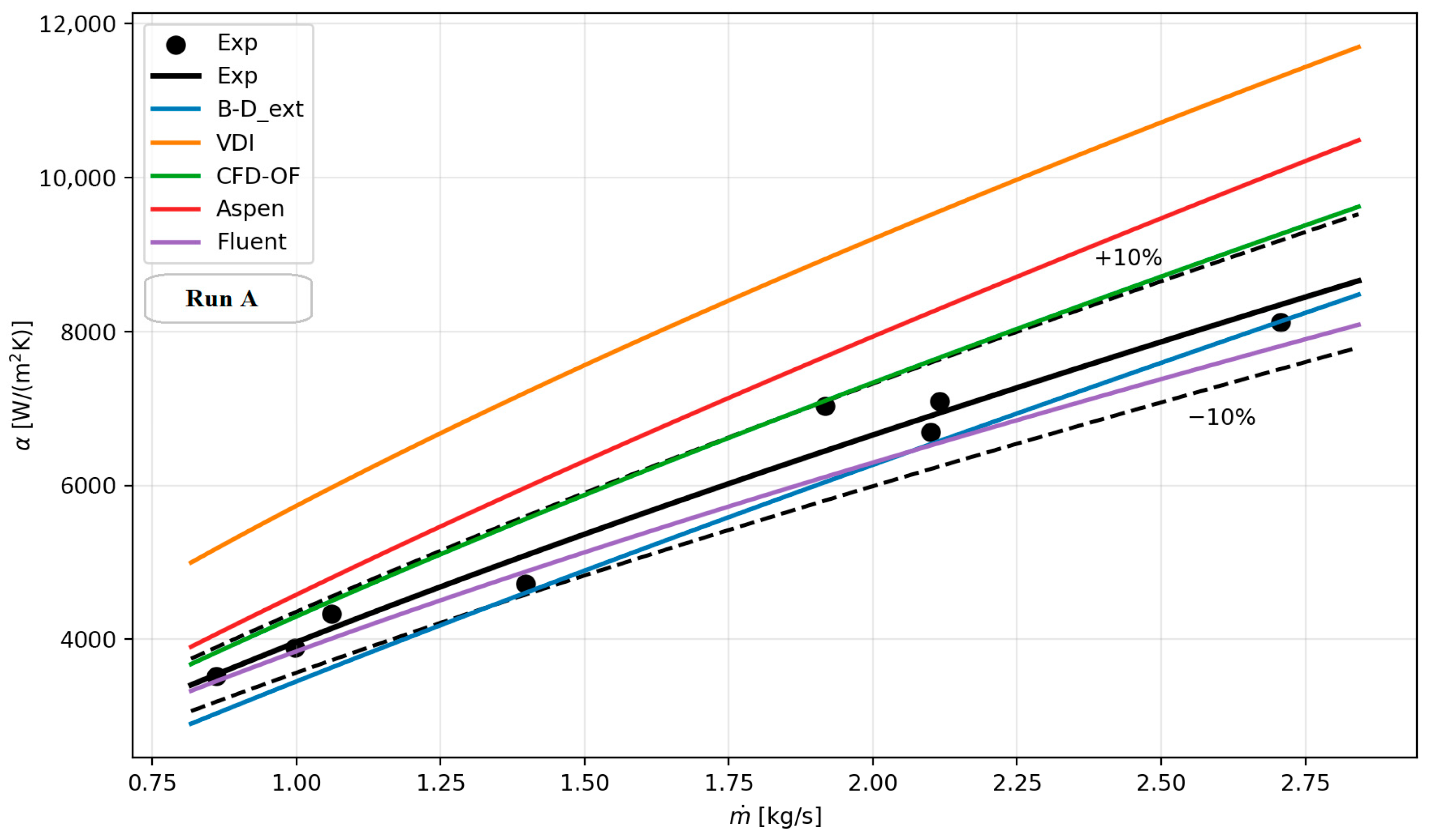
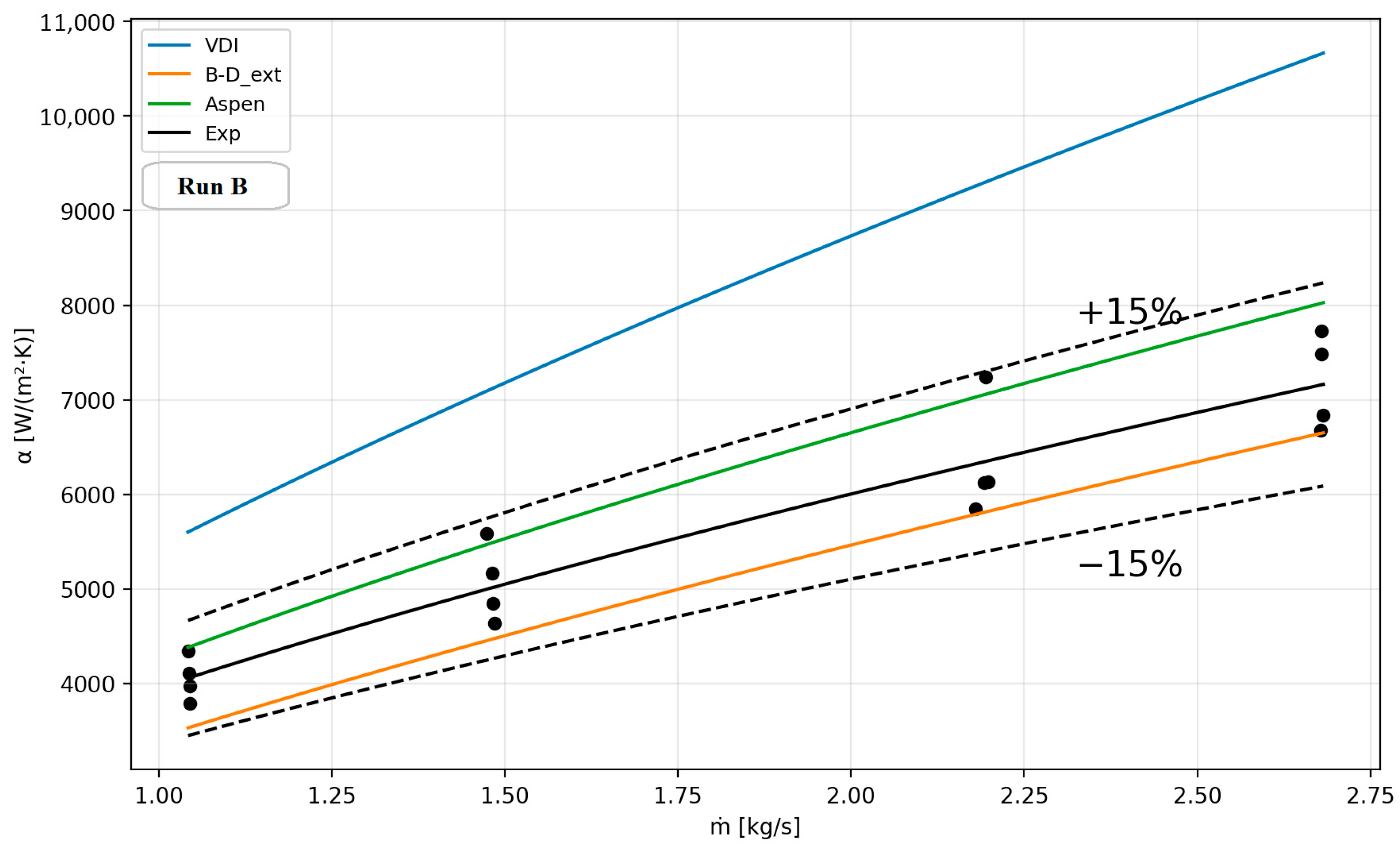
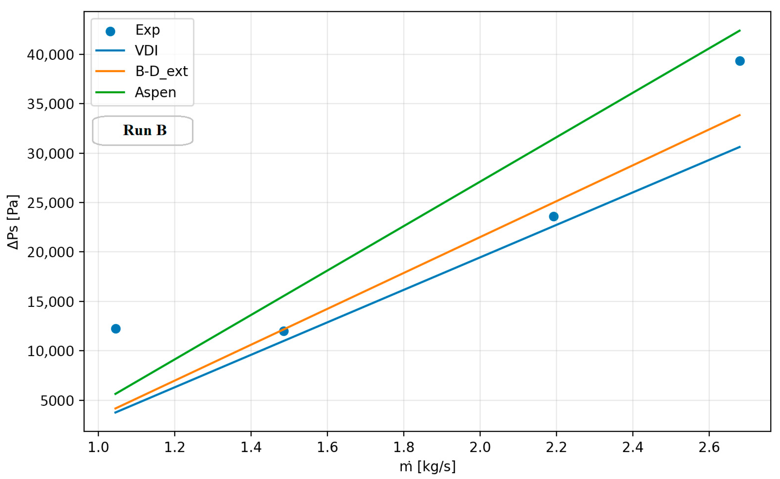
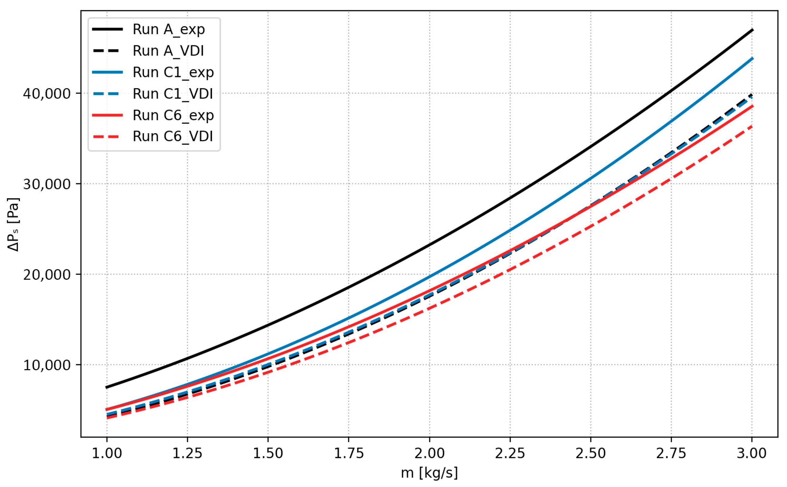
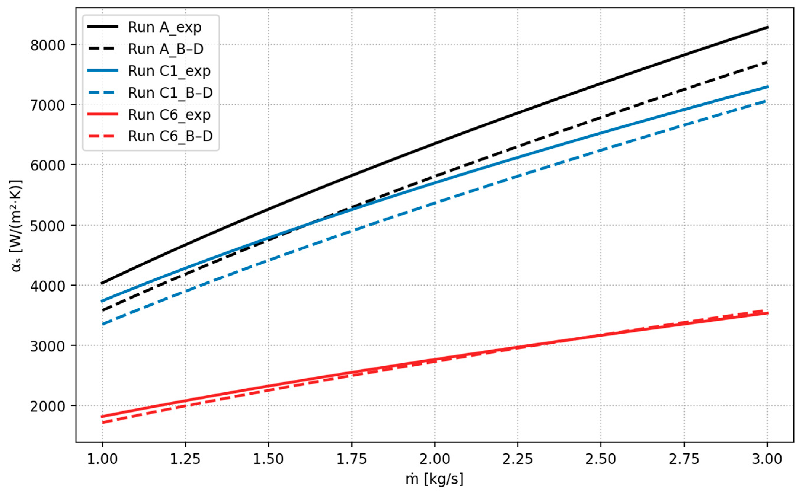
- The VDI method gives the highest shell-side HTC compared to the other tested methods. Characteristically, it overestimates the shell-side HTC the smaller the clearances are. The VDI method overestimates the heat transfer coefficient by approximately 33% and underestimates the pressure drop by about 20%, relative to the experimental data.
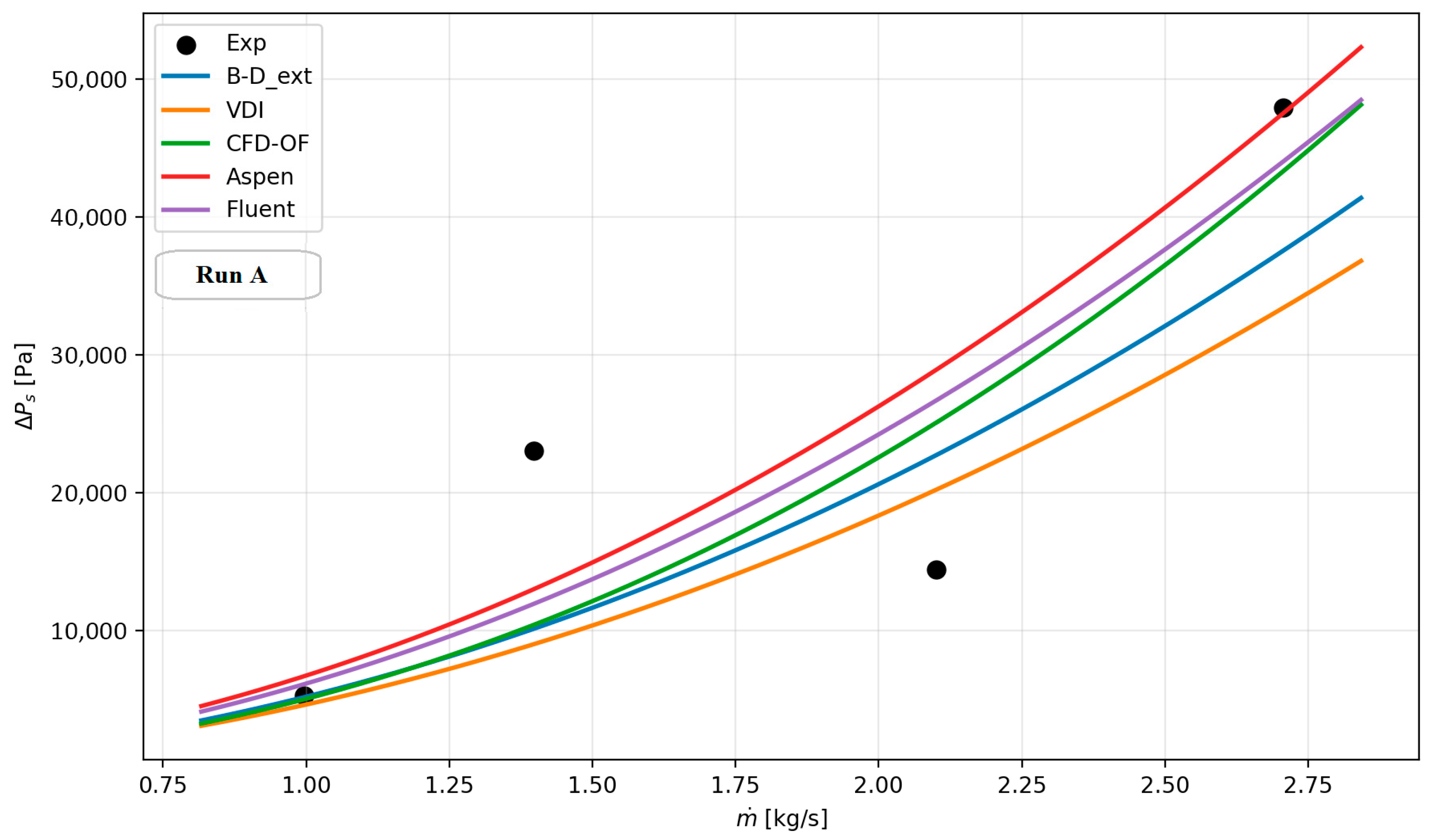
- The extended Bell–Delaware method reproduces the experimental data accurately for both shell-side HTC and pressure drop, although it most often slightly underestimates them. The extended Bell–Delaware method shows the highest agreement with the experimental results, reproducing the data within a ±10% band.
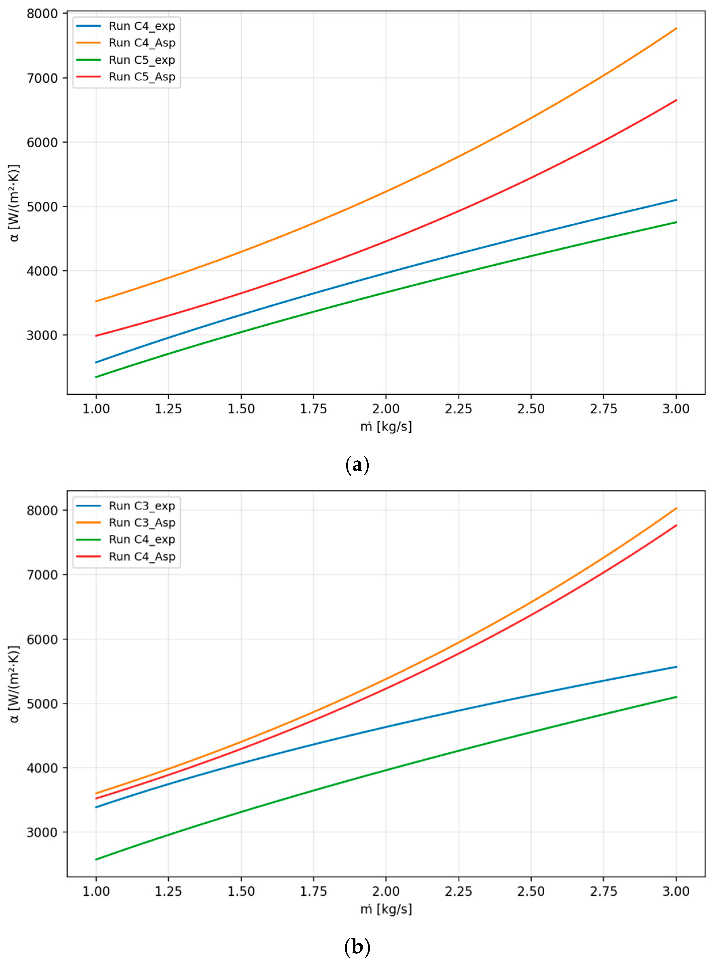
- Aspen EDR accurately reproduces both the experimental shell-side HTC and the pressure drop over the entire range of tested clearances, with a discrepancy not exceeding ±17%.
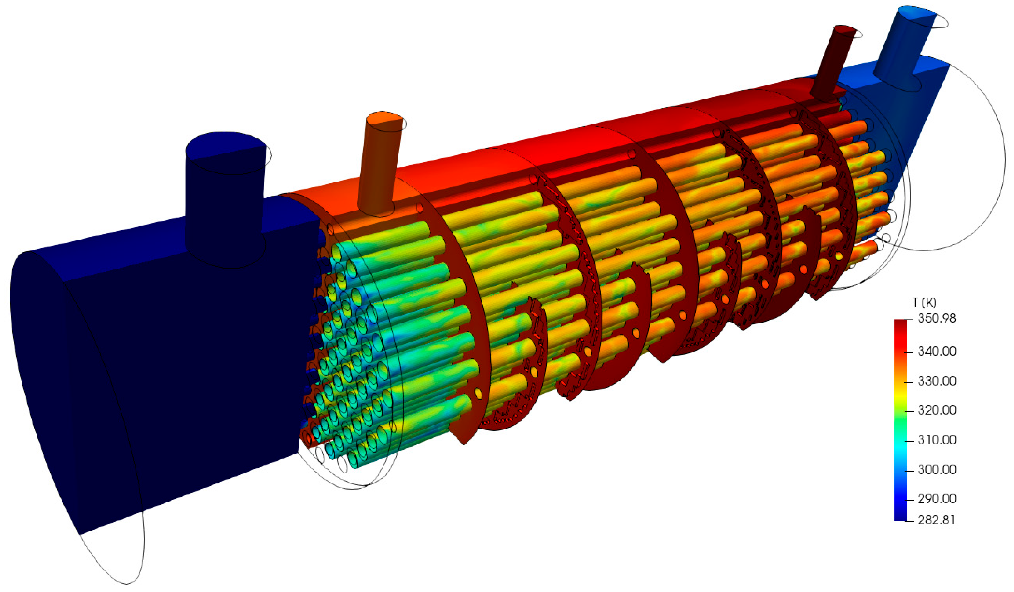
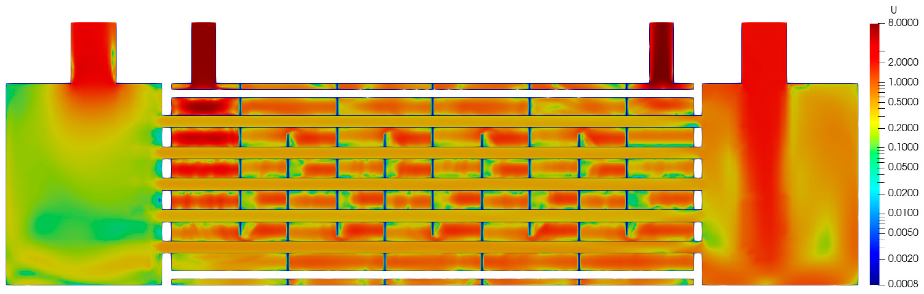
- CFD simulations (using both OpenFOAM and Ansys Fluent), conducted only for a quasi-ideal STHEx (without leakages), showed good agreement with the experimental data. The OpenFOAM and Ansys Fluent simulations reproduced a mean HTC within a ±10% range. Regarding the shell-side pressure drop, the OpenFOAM and Ansys Fluent calculations yielded values approximately 4% lower than those predicted by Aspen EDR, which provided the most accurate agreement with the experimental data. However, the computation time for a single set of input data exceeded 12 h (Xeon 8173m processor, 13/28 cores involved); therefore, this approach is better suited to optimizing STHEx designs rather than being used during the design stage, especially in the preliminary design stage.
- The experiments and calculations confirmed both a reduction in flow resistance (pressure drop) and the shell-side HTC as the clearances’ cross-sectional area increased. However, while the maximum pressure drop decreased by about 12%, the shell-side HTC decreased by as much as 52% compared to the quasi-ideal STHEx. Such a small reduction in pressure drop results from the fact that the main contribution to the total pressure drop comes from the nozzle pressure drop due to expansion at the inlet nozzle and contraction at the outlet nozzle, which is practically independent of the clearance size. Increasing the cross-sectional area of the baffle-to-tube and shell-to-baffle clearances reduces the fraction of fluid flowing perpendicular (which is desirable) to the tubes and increases the fraction of fluid flowing parallel to the tubes, which leads to a significant decrease in shell-side HTC.
- From a practical point of view, the reduction in pressure drop, resulting from the increase in the clearances’ cross-sectional area, leads to a decrease in pumping power and, consequently, to lower heat-exchanger operating costs. On the other hand, a decrease in the HTC (in the analyzed case, even exceeding 50%) may mean that the heat exchanger must have a larger heat transfer area, which results in greater material consumption and higher energy use during its manufacturing. Therefore, both the long-term operating costs and capital costs of the heat exchanger should be evaluated very carefully, while also taking into account the significantly higher manufacturing costs of a heat exchanger with small clearances, especially in the case of a large number of baffles and tubes in the bundle.
Author Contributions
Funding
Data Availability Statement
Conflicts of Interest
Nomenclature
| Ao | Heat transfer area | [m2] | |
| cp | Specific heat | [J/(kgK)] | |
| do | Ouside tube diameter | [m] | |
| dB | Hole diameter | [m] | |
| D1 | Baffle diameter | [m] | |
| Ds | Inside shell diameter | [m] | |
| g | Acceleration due to gravity | [m/s2] | |
| Mass flow rate | [kg/s] | ||
| Nu | Nusselt number | [[-] | |
| ΔP | Pressure difference | [Pa] | |
| Heat flow rate | [W] | ||
| T | Temperature | [K] | |
| u | Velocity | [m/s] | |
| Greek letters | |||
| α | Heat transfer coefficient | [W/(m2K)] | |
| δd | Baffle-to-tube gap width | [m] | |
| δD | Shell-to-baffle gap width | [m] | |
| λ | Thermal conductivity | [W/(mK)] | |
| ρ | Density | [kg/m3] | |
| μ | Dynamic viscosity | [Pas] | |
| τ | Time | [s] | |
| Subscripts | |||
| C | Cold | ||
| H | Hot | ||
| id | Ideal | ||
| in | Inlet | ||
| out | Outlet | ||
| r | Reference | ||
| s | Shell | ||
| t | Tube | ||
| w | Wall | ||
| Abbreviations | |||
| CFD | Computational Fluid Dynamics | ||
| HTC | Heat Transfer Coefficient | ||
| OF | OpenFOAM | ||
| STHEx | Shell-and-Tube Heat Exchanger | ||
| VDI | Verein Deutscher Ingenieure | ||
References
- Master, B.I.; Chunangad, K.S.; Boxma, A.J.; Kral, D.; Stehlík, P. Most Frequently Used Heat Exchangers from Pioneering Research to Worldwide Applications. Heat Transf. Eng. 2006, 27, 4–11. [Google Scholar] [CrossRef]
- Sagar, J.P.; Ankith, B.; Rao, P.S.; Reddy, P.R.; Elipey, M.K. A review on heat transfer enhancement methods for a heat exchanger. AIP Conf. Proc. 2022, 2648, 040005. [Google Scholar] [CrossRef]
- Marzouk, S.A.; Abou Al-Sood, M.M.; El-Said, E.M.S.; Younes, M.M.; El-Fakharany, M.K. A comprehensive review of methods of heat transfer enhancement in shell and tube heat exchangers. J. Therm. Anal. Calorim. 2023, 148, 7539–7578. [Google Scholar] [CrossRef]
- Gobinathan, S.N.; Aziz, A.A.; Oumer, A.N.; Taib, M.Y.; Alias, A.B.S. A Review on Heat Transfer Enhancement in a Heat Exchanger. J. Adv. Res. Fluid Mech. Therm. Sci. 2024, 122, 130–145. [Google Scholar] [CrossRef]
- Bichkar, P.; Dandgaval, O.; Dalvi, P.; Godase, R.; Dey, T. Study of Shell and Tube Heat Exchanger with the Effect of Types of Baffles. Procedia Manuf. 2018, 20, 195–200. [Google Scholar] [CrossRef]
- Arani, A.A.A.; Moradi, R. Shell and tube heat exchanger optimization using new baffle and tube configuration. Appl. Therm. Eng. 2019, 157, 113736. [Google Scholar] [CrossRef]
- Omar, H.; Alfaraw, S.; El-sawi1, A.; Alobeidy, H. Study the Effect of Baffle Spacing on Heat Transfer and Pressure Drop in Shell and Tube Heat Exchanger. J. Adv. Res. Numer. Heat Transf. 2021, 6, 22–30. [Google Scholar]
- Marzouk, S.A.; Abou Al-Sood, M.M.; El-Fakharany, M.K.; El-Said, E.M.S. A comparative numerical study of shell and multi-tube heat exchanger performance with different baffles configurations. Int. J. Therm. Sci. 2023, 179, 107655. [Google Scholar] [CrossRef]
- Mohammadzadeh, A.M.; Jafari, B.; Hosseinzadeh, K. Comprehensive numerical investigation of the effect of various baffle design and baffle spacing on a shell and tube heat exchanger. Appl. Therm. Eng. 2024, 249, 123305. [Google Scholar] [CrossRef]
- Tinker, T. Shell Side Characteristics of Shell and Tube Heat Exchanger, Parts I-III, General Discussion of Heat Transfer; Institution of Mechanical Engineers: London, UK; ASME: New York, NY, USA, 1951; pp. 84–110. [Google Scholar]
- Tinker, T. Shell-Side Characteristics of Shell and Tube Heat Exchanger. J. Heat Transf. 1958, 80, 36–52. [Google Scholar]
- Bell, K.J. Exchanger Design—Based on the Delaware Research Program. Petro/Chem Eng. 1960, 32, C-26–C-40c. [Google Scholar]
- Bell, K.J. Final Report of the Cooperative Research Program on Shell and Tube Heat Exchangers; Bulletin No. 5; University of Delaware Engineering Experimental Station: Newark, DE, USA, 1963. [Google Scholar]
- Gaddis, E.S.; Gnielinski, V. Pressure drop on the shell side of shell-and-tube heat exchangers with segmental baffles. Chem. Eng. Process 1977, 36, 149–159. [Google Scholar] [CrossRef]
- Gnielinski, V.; Gaddis, E.S. Berechnung des mittlerenWärmeübergangskoeffizienten im Außenraum von Rohrbündelwärmeaustauschern mit Segment-Umlenkblechen. Vt Verfahrenstechnik 1978, 12, 211–217. [Google Scholar]
- Estupiñan-Campos, J.; Quitiaquez, W.; Nieto-Londono, C.; Quitiaquez, P. Numerical simulation of the heat transfer inside a shell and tube heat exchanger considering different variations in the geometric parameters of the design. Energies 2024, 17, 691. [Google Scholar] [CrossRef]
- Khan, A.; Shah, I.; Gul, W.; Khan, T.A.; Ali, Y.; Masood, S.A. Numerical and experimental analysis of shell and tube heat exchanger with round and hexagonal tubes. Energies 2023, 16, 880. [Google Scholar] [CrossRef]
- Hoang, H.M.K.; Cao, H.-L.; Pham, P.M.Q.; Hajjar, A.; Nguyen, V.L. A novel shell-and-tube heat exchanger design with alternative inclined baffles. Case Stud. Therm. Eng. 2025, 65, 105542. [Google Scholar] [CrossRef]
- Waleed, M.; Naqvi, S.M.A.; Mustafa, H.; Al Mesfer, M.K.; Danish, M.; Irshad, K.; Shahzad, H. Numerical analysis of shell and tube heat exchanger with combination of different baffles. Case Stud. Therm. Eng. 2025, 65, 105658. [Google Scholar] [CrossRef]
- Adebayo, J.K.; Dare, A.A.; Petinrin, M.O. Performance characteristics of shell and tube heat exchanger using sectoral baffle. J. Eng. Appl. Sci. 2025, 72, 13. [Google Scholar] [CrossRef]
- Prithiviraj, M.; Andrews, M.J. Comparison of a Three-Dimensional Numerical Model with Existing Methods for Prediction of Flow in Shell-and-Tube Heat Exchangers. Heat Transf. Eng. 1999, 20, 15–19. [Google Scholar]
- Kapale, U.C.; Satish Chand, S. Modeling for shell-side pressure drop for liquid flow in shell-and-tube heat exchanger. Int. J. Heat Mass Transf. 2006, 49, 601–610. [Google Scholar] [CrossRef]
- Parikshit, B.; Spandana, K.R.; Krishna, V.; Seetharam, T.R.; Seetharamu, K.N. A simple method to calculate shell side fluid pressure drop in a shell and tube heat exchanger. Int. J. Heat Mass Transf. 2015, 84, 700–712. [Google Scholar] [CrossRef]
- Kücük, H.; Ünverdi, M.; Yılmaz, M.S. Experimental investigation of shell side heat transfer and pressure drop in a mini-channel shell and tube heat exchanger. Int. J. Heat Mass Transf. 2019, 143, 118493. [Google Scholar] [CrossRef]
- Abdelkader, B.A.; Zubair, S.M. The Effect of a Number of Baffles on the Performance of Shell-and-Tube Heat Exchangers. Heat Transf. Eng. 2019, 40, 39–52. [Google Scholar] [CrossRef]
- Alperen, M.A.; Kayabaşi, E.; Hüseyin Kurt, H. Detailed comparison of the methods used in the heat transfer coefficient and pressure loss calculation of shell side of shell and tube heat exchangers with the experimental results. Energy Sources Part A Recovery Util. Environ. Eff. 2023, 45, 5661–5680. [Google Scholar] [CrossRef]
- Di Bono, G.; Corcione, M.; Quintino, A. Systematic comparative analysis of Kern and Bell-Delaware methods for the design of shell-and-tube heat exchangers. Appl. Therm. Eng. 2025, 278, 127327. [Google Scholar] [CrossRef]
- Mahdi, A.S.M. Effect of Baffle Gaps on Heat Transfer in a Shell-and-Tube Heat Exchanger. Ph.D. Thesis, Gdańsk University of Technology, Gdańsk, Poland, 1978. (In Polish) [Google Scholar]
- Serth, R.W.; Lestina, T.G. Process Heat Transfer; Elsevier: Amsterdam, The Netherlands, 2014. [Google Scholar]
- Thome, J. Wolverine Heat Transfer Engineering Data Book III; Wolverine Tube, Inc.: Huntsville, AL, USA, 2010. [Google Scholar]
- Gaddis, E.S.; Gnielinski, V. G8 Shell-Side Heat Transfer in Baffled Shell-and-Tube Heat Exchangers. In VDI Heat Atlas; Springer: Berlin/Heidelberg, Germany, 2010; pp. 731–741. [Google Scholar]
- Gaddis, E.S. L1.5 Pressure Drop in the Outer Shell of Heat Exchangers. In VDI Heat Atlas; Springer: Berlin/Heidelberg, Germany, 2010; pp. 1092–1105. [Google Scholar]
- Menter, F. Two-equations eddy-viscosity turbulence models for engineering applications. AIAA-J. 1994, 32, 1598–1605. [Google Scholar] [CrossRef]
- OpenFOAM. Available online: https://www.openfoam.com (accessed on 2 March 2025).
- Ansys Fluent, Version 19.3. Fluent 19.3 user’s guide. Ansys Inc.: Canonsburg, PA, USA, 2018.
- AspenTech. Aspen Exchanger Design and Rating, V15.0; AspenTech Inc.: Bedford, MA, USA, 2023.
- Palen, J.W.; Taborek, J. Solution of Shellside Flow Pressure Drop and Heat Transfer by Stream Analysis Method. Chem. Eng. Prog. Symp. Ser. 1969, 65, 53–63. [Google Scholar]
- Lemmon, E.W.; Huber, M.L.; McLinden, M.O. NIST Standard Reference Database 23, Reference Fluid Thermodynamic and Transport Properties (REFPROP), Version 9.0; National Institute of Standards and Technology: Gaithersburg, MD, USA, 2010.



| Item | Value/Type |
|---|---|
| Shell inner diameter | 200.2 mm |
| Length of shell | 518 mm |
| Total tube number | 85 |
| OD/ID tube diameter | 12/10 mm |
| Tube layout | Triangular (30°) |
| Tube pitch | 1.5 |
| Total number of baffles | 9 |
| Baffle cut | 25% |
| Central baffle spacing | 48 mm |
| Inlet and outlet sections | 67 mm |
| Hot fluid mass flow rate | 1–3 kg/s |
| Cold fluid mass flow rate | 3 kg/s |
| Inlet hot fluid temperature | 35–79 °C |
| Cold fluid inlet temperature | 7.5–11 °C |
| Run | Flow Configuration | ||||
|---|---|---|---|---|---|
| A | 0.0 | 0.0120 | 0.0 | 0.2002 | No baffle-to-tube and shell-to-baffle leakages. |
| B | 0.00012 | 0.01224 | 0.0 | 0.2002 | No shell-to-baffle leakage; only baffle-to-tube leakage occurred. |
| C1 | 0.00012 | 0.01224 | 0.0001 | 0.2000 | Both shell-to-baffle and baffle-to-tube leakages were present. |
| C2 | 0.00012 | 0.01224 | 0.0007 | 0.1988 | Both shell-to-baffle and baffle-to-tube leakages were present. |
| C3 | 0.00025 | 0.01250 | 0.0007 | 0.1988 | Both shell-to-baffle and baffle-to-tube leakages were present. |
| C4 | 0.00025 | 0.01250 | 0.0012 | 0.1978 | Both shell-to-baffle and baffle-to-tube leakages were present. |
| C5 | 0.00050 | 0.0130 | 0.0012 | 0.1978 | Both shell-to-baffle and baffle-to-tube leakages were present. |
| C6 | 0.00050 | 0.0130 | 0.0025 | 0.1952 | Both shell-to-baffle and baffle-to-tube leakages were present. |
Disclaimer/Publisher’s Note: The statements, opinions and data contained in all publications are solely those of the individual author(s) and contributor(s) and not of MDPI and/or the editor(s). MDPI and/or the editor(s) disclaim responsibility for any injury to people or property resulting from any ideas, methods, instructions or products referred to in the content. |
© 2026 by the authors. Licensee MDPI, Basel, Switzerland. This article is an open access article distributed under the terms and conditions of the Creative Commons Attribution (CC BY) license.
Share and Cite
Cieśliński, J.T.; Barański, J.; Dąbrowski, P.; Fabrykiewicz, M.; Stasiak, K.; Tesch, K. Heat Transfer and Pressure Drop in a Shell-and-Tube Heat Exchanger with Segmental Baffles. Energies 2026, 19, 1760. https://doi.org/10.3390/en19071760
Cieśliński JT, Barański J, Dąbrowski P, Fabrykiewicz M, Stasiak K, Tesch K. Heat Transfer and Pressure Drop in a Shell-and-Tube Heat Exchanger with Segmental Baffles. Energies. 2026; 19(7):1760. https://doi.org/10.3390/en19071760
Chicago/Turabian StyleCieśliński, Janusz T., Jacek Barański, Paweł Dąbrowski, Maciej Fabrykiewicz, Kamil Stasiak, and Krzysztof Tesch. 2026. "Heat Transfer and Pressure Drop in a Shell-and-Tube Heat Exchanger with Segmental Baffles" Energies 19, no. 7: 1760. https://doi.org/10.3390/en19071760
APA StyleCieśliński, J. T., Barański, J., Dąbrowski, P., Fabrykiewicz, M., Stasiak, K., & Tesch, K. (2026). Heat Transfer and Pressure Drop in a Shell-and-Tube Heat Exchanger with Segmental Baffles. Energies, 19(7), 1760. https://doi.org/10.3390/en19071760