1. Introduction
Laminated cooling plates are key thermal-management components in advanced energy systems, where lightweight design must be achieved without compromising heat-spreading and cooling performance. Their internal flow channels and supporting pillars result in significantly reduced and spatially non-uniform stiffness, which can substantially modify the restraint conditions during fabrication. Fusion welding is widely used to manufacture such components because of its high efficiency and material utilization. However, the localized moving heat input generates a strongly non-uniform thermal cycle, together with rapid transient heat conduction through the thin walls and continuous surface heat loss, making residual stresses and welding-induced distortion largely unavoidable. This issue is particularly critical in thin-walled structures for energy equipment, where the low bending stiffness makes them highly susceptible to angular and bending deformation, thereby compromising dimensional accuracy, assembly tolerance, and ultimately service reliability. Consequently, developing predictive and mechanistic approaches for welding distortion in thin-walled laminated cooling plates remains an important topic at the intersection of heat-transfer analysis and thermo-mechanical response. Horajski et al. [
1] proposed an integrated structural–process strategy for reducing distortion in thin-walled welded structures and emphasized the continuing practical importance of deformation control in engineering applications. Qiu et al. [
2] further showed that welding-induced distortion can amplify stresses and affect fatigue assessment, indicating that distortion is not merely a geometric imperfection, but also a factor that propagates into strength evaluation and safety margins. Experimental and numerical studies [
3,
4,
5] have also shown that geometric scale, such as plate dimensions, and boundary constraints strongly influence both welding deformation and residual stress. These findings suggest that predictive models should be established on a mechanistic basis rather than relying solely on empirical corrections.
Factors influencing welding deformation mainly include the dimensions of the base metal, plate thickness, clamping conditions, and welding parameters [
6]. For properly assembled thin-walled structures, welding deformation is mainly governed by the highly non-uniform temperature field generated during welding and by the intrinsically low stiffness of thin plates, which makes them less resistant to deformation [
7]. From a mechanics perspective, welding deformation originates from non-recoverable inelastic strains accumulated under strongly non-uniform thermal cycles. In most fusion-welding processes, plastic strain is the dominant component, which forms the basis of the inherent strain concept [
8,
9]. Within this framework, the complex thermo-mechanical process is represented by an equivalent inelastic strain field, and the resulting global deformation is obtained by applying this field to the structure [
10]. Following this concept, Lee et al. [
11] developed a layered shell-element inherent strain method for thin-plate structures, improving computational efficiency for large-scale problems, and further proposed a time-saving workflow for predicting inherent deformation in large welded structures [
12], thereby demonstrating its engineering applicability. To improve prediction accuracy, Wang et al. [
13] introduced a stepwise loading strategy for inherent strains and validated its effectiveness in stiffened plate structures, showing that the loading scheme can significantly influence the final distortion field. Despite these advances in computational efficiency and predictive capability, a central issue remains insufficiently understood: why plastic strain evolves in a particular manner and how its spatial distribution is governed, especially under conditions of non-uniform stiffness and non-uniform restraint. In practice, the inherent strain field is still often treated as a black-box input, which limits the interpretability of distortion mechanisms and the transferability of distortion-control strategies.
The onset and evolution of plasticity during welding are governed by the combined effects of transient temperature gradients, temperature-dependent material properties, and structural constraints/stiffness [
14]. A highly reliable understanding of plastic strain formation therefore typically requires thermo-mechanical coupled analysis [
15]. Park et al. [
16] numerically investigated the role of transverse restraint in welding distortion and residual stress, demonstrating that boundary conditions can fundamentally alter the final distortion mode and stress level. Chen et al. [
17] analyzed residual stress distributions in U-rib stiffened plates, highlighting how stiffeners redistribute local restraint and, consequently, the stress/strain fields. Xu et al. [
18] conducted experimental and numerical studies on residual stress and distortion in welded “I”-section curved beams, showing that section non-uniformity and curvature modify the deformation response. Collectively, these studies indicate a strong coupling between structural stiffness/constraint and welding response. However, most of the existing literature still evaluates outcomes mainly through final-state distortion or residual stress, while systematic and transferable explanations are scarce for how stiffness influences the restraint path and thereby governs the temporal evolution and spatial distribution of plastic strain.
This limitation becomes more pronounced for thin-walled laminated structures. Compared with conventional plates, internal channels and supporting pillars introduce pronounced spatially non-uniform stiffness, which may change how thermal strain is constrained and how the plastic zone develops. In contrast, the current research on laminated configurations has largely focused on thermal management and cooling performance [
19,
20], and an explicit framework is still lacking for interpreting plastic strain formation mechanisms, dominant components, and the conditions under which the spatial distribution transitions in welded joints with non-uniform stiffness.
To address these gaps, this work establishes an experimentally validated thermo-mechanical finite element model that explicitly accounts for the non-uniform stiffness characteristics of GH3230 laminated plates and systematically analyzes the initiation and evolution of plastic strain during the welding thermal cycle. By comparison with a conventional plate joint, the influence of non-uniform stiffness on plastic-strain evolution is identified and summarized. On this basis, an equivalent restraint–stiffness spring model is further proposed to parameterize how stiffness reduction and changes in the restraint path affect plastic-strain distributions, thereby providing actionable structural and process-oriented guidance for distortion control of thin-walled laminated welded components.
4. Results and Discussion
4.1. Validation of Thermal Analysis
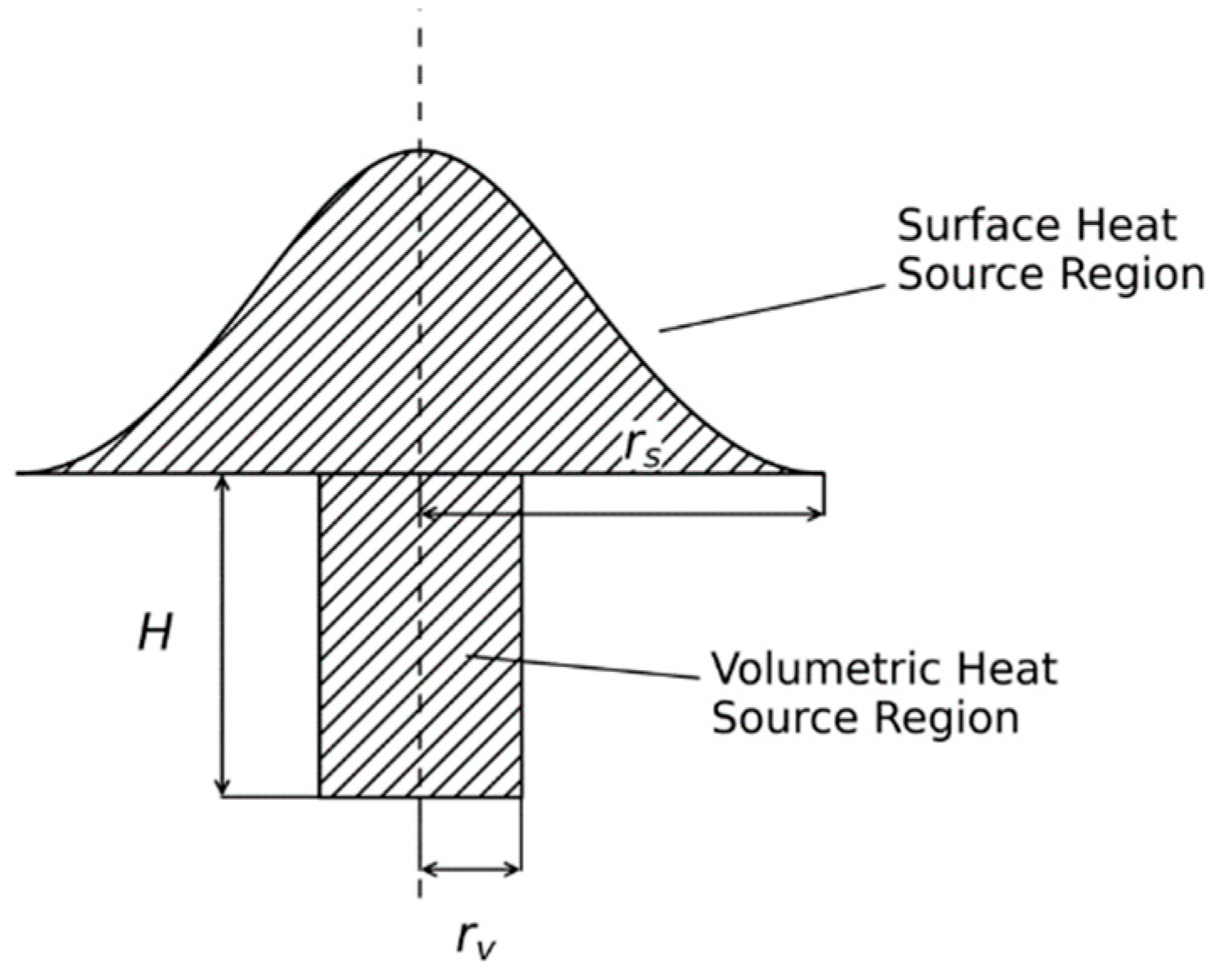
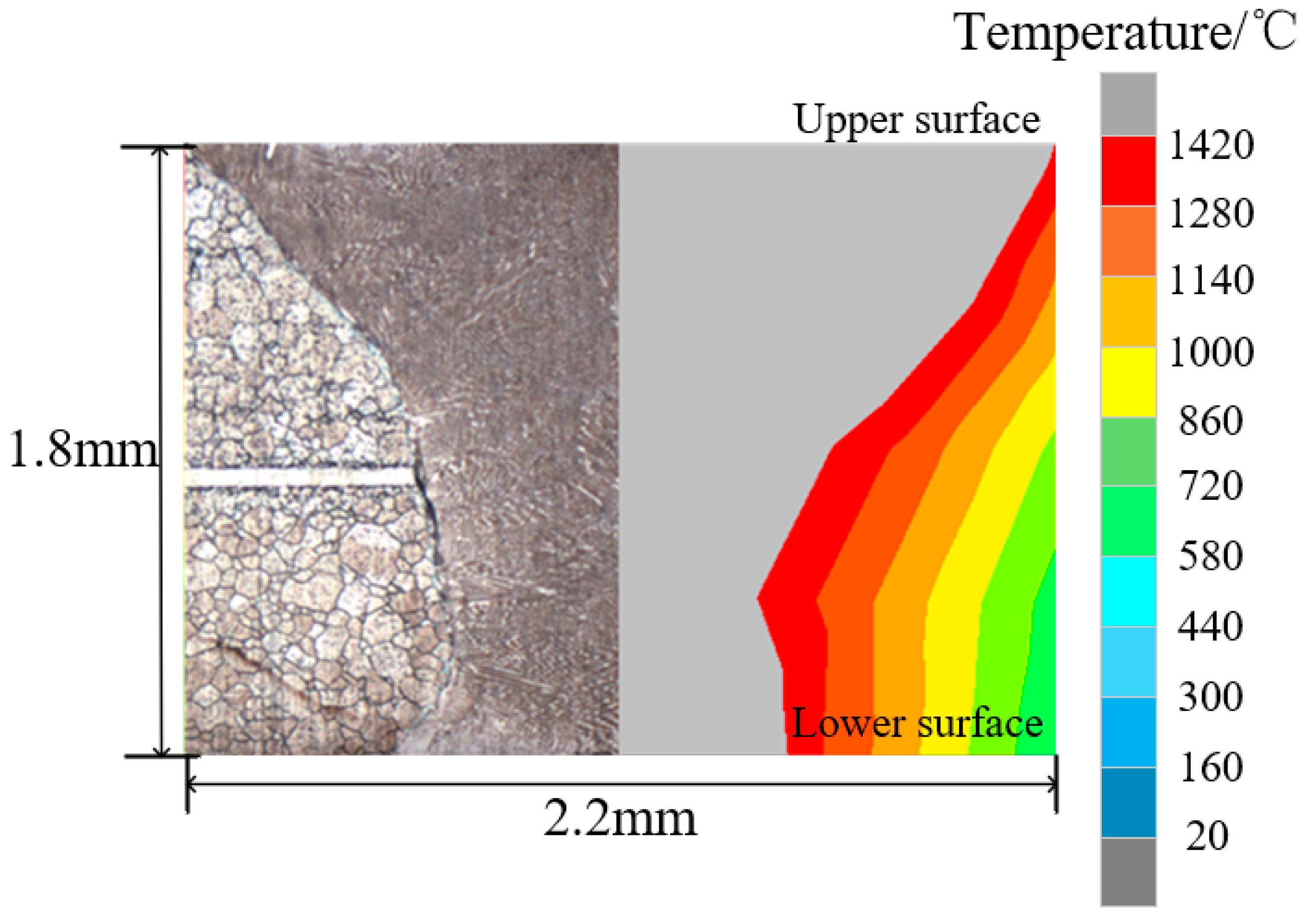
Figure 7 compares the simulated transient temperature field with the macrograph of the experimental weld cross-section. The fusion-zone geometry provides an integral validation of the underlying heat-transfer description, because it reflects the balance between the imposed moving heat input and the subsequent heat dissipation/spreading through the plate thickness and along the surface. The results confirm that the adopted heat-source model can reproduce the experimentally observed fusion zone of the laser weld. Full penetration was achieved in the experiment, and the fusion width on the top surface was approximately 2.2 mm; the simulation predicts an essentially identical weld-pool profile under the same heat-source parameters and heat-transfer boundary conditions. Therefore, the calibrated thermal model offers a consistent and reliable basis for subsequent thermo-mechanical analysis, and for isolating the effect of structural stiffness non-uniformity under a fixed thermal (heat-transfer) baseline.
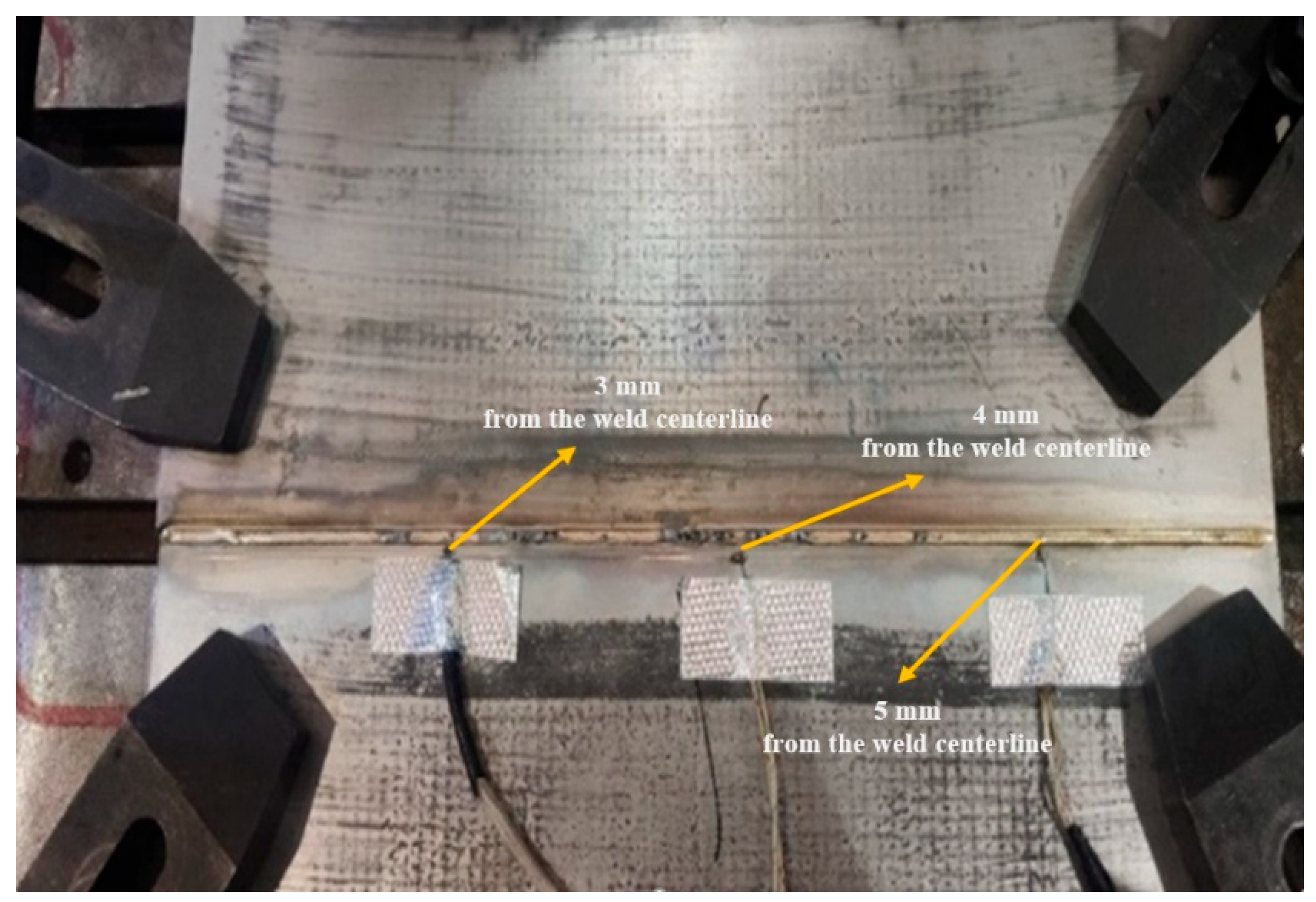
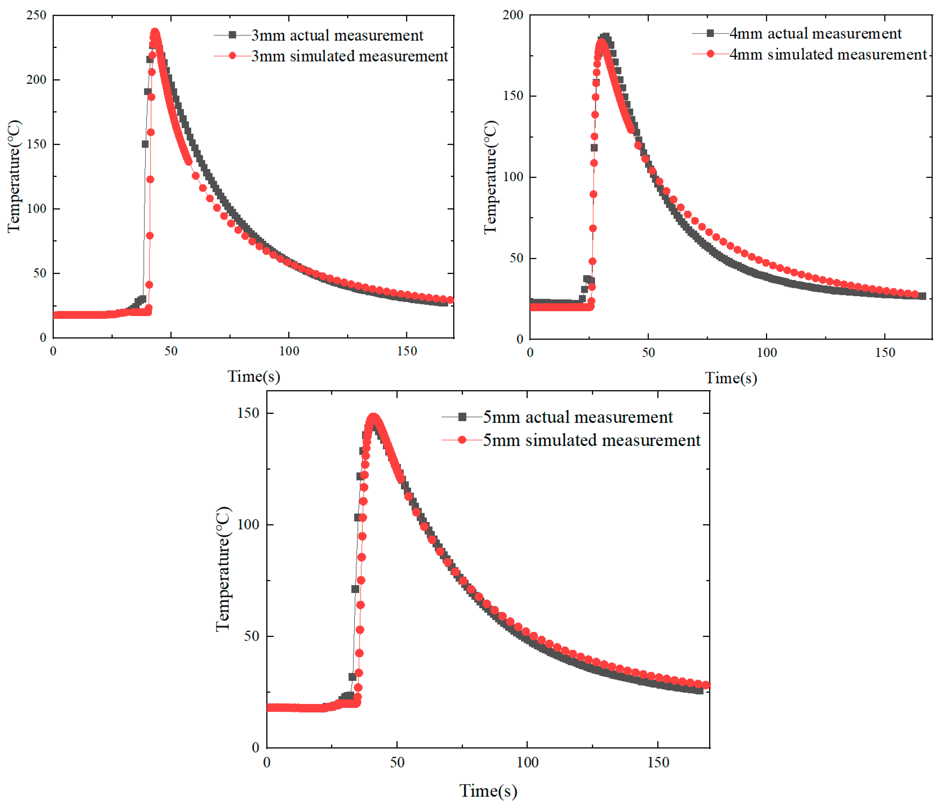
To ensure reliable thermal predictions, the simulated thermal cycles near the weld were compared with the experimentally measured results. The comparison is shown in
Figure 8. Both the experimental measurements and the finite element results were taken at the material surface.
The thermal histories measured at 3, 4, and 5 mm from the weld centerline exhibit a clear spatial attenuation of the peak temperature with increasing distance, reflecting the combined effects of localized heat input and subsequent heat spreading through conduction and surface heat loss.
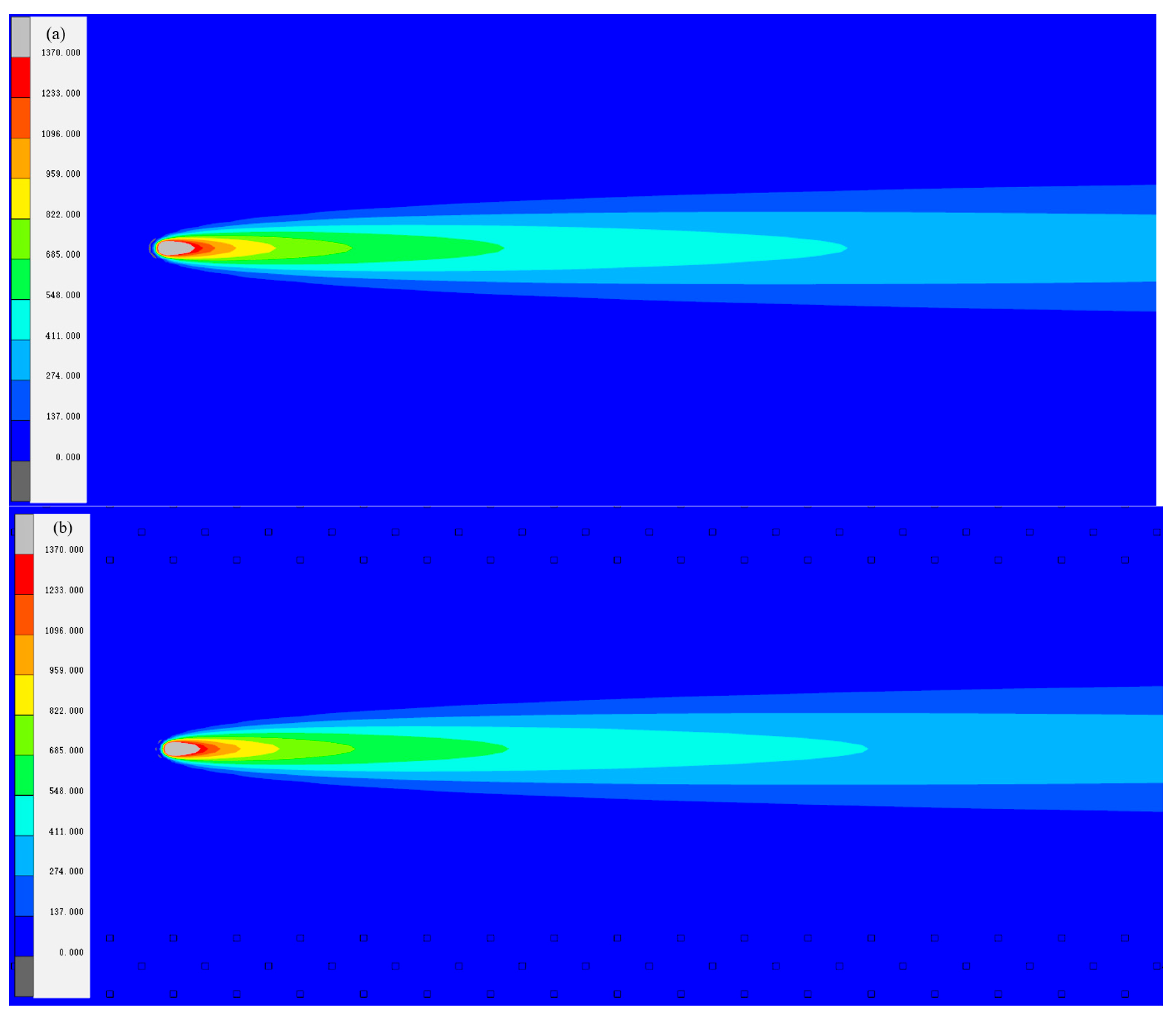
Figure 9 further compares the transient temperature fields of the solid and laminated plates during the steady welding stage. In both cases, the isotherms exhibit a characteristic elongated teardrop-shaped pattern, which is associated with the highly concentrated energy input of the laser heat source and its high travel speed. The high-temperature zone is confined to the vicinity of the weld, and the isotherms are stretched along the welding direction. Owing to rapid heat spreading/conduction in thin plates and surface heat losses, the transverse temperature gradient remains very steep. Under identical heat-source parameters and heat-transfer boundary conditions, the overall heat-affected region and the melting-boundary isotherm are comparable for the two configurations, indicating that the subsequent differences in plastic-strain localization and distortion are mainly attributed to stiffness-dependent restraint redistribution.
The numerical results reproduce the full heating–peak–cooling sequence with good agreement, capturing both the rapid temperature rise during heat-source passage and the post-heating decay governed by heat dissipation. This agreement indicates that the adopted moving heat-source representation, together with the applied thermal boundary conditions, can reliably describe the transient heat-transfer process in laser welding. The validated thermal model is therefore taken as a consistent heat-transfer baseline for the subsequent thermo-mechanical coupled analysis and welding-distortion prediction.
4.2. Welding Residual Stress and Distortion
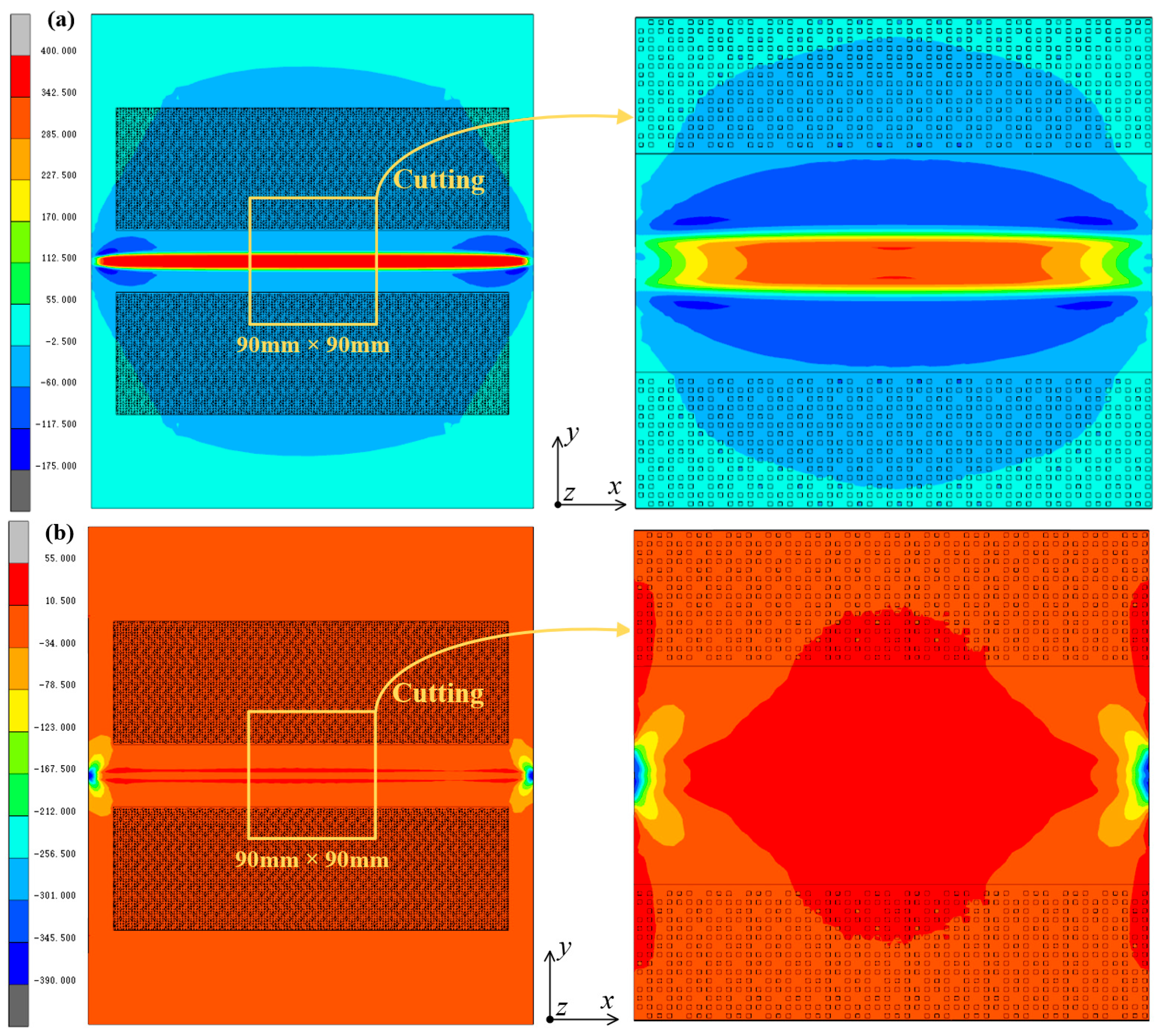
The simulated stress-relief effect induced by cutting is shown in
Figure 10. Both the longitudinal and transverse residual stresses are released to different extents after cutting, while boundary effects remain evident. As a result, the peak longitudinal residual stress decreases after cutting, whereas the maximum transverse residual stress shows a moderate increase.
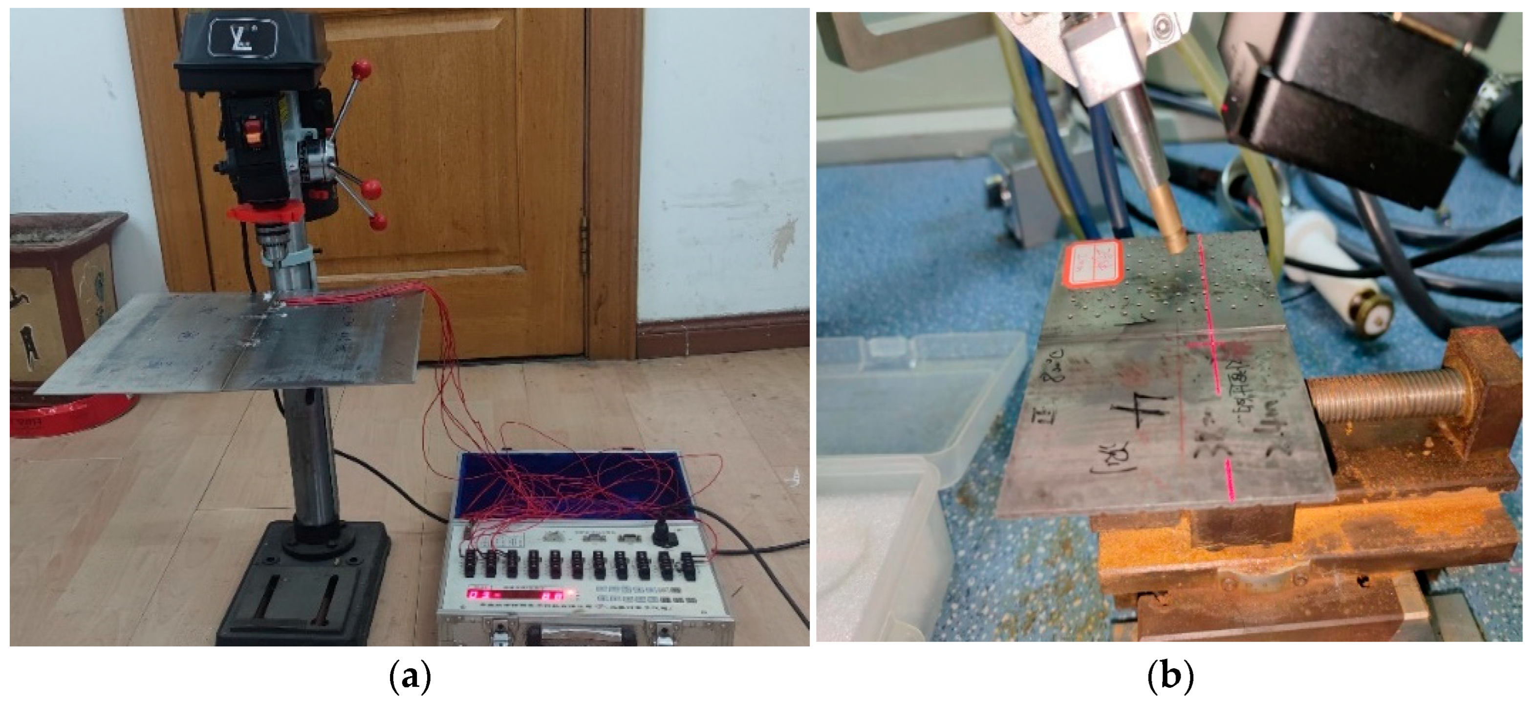
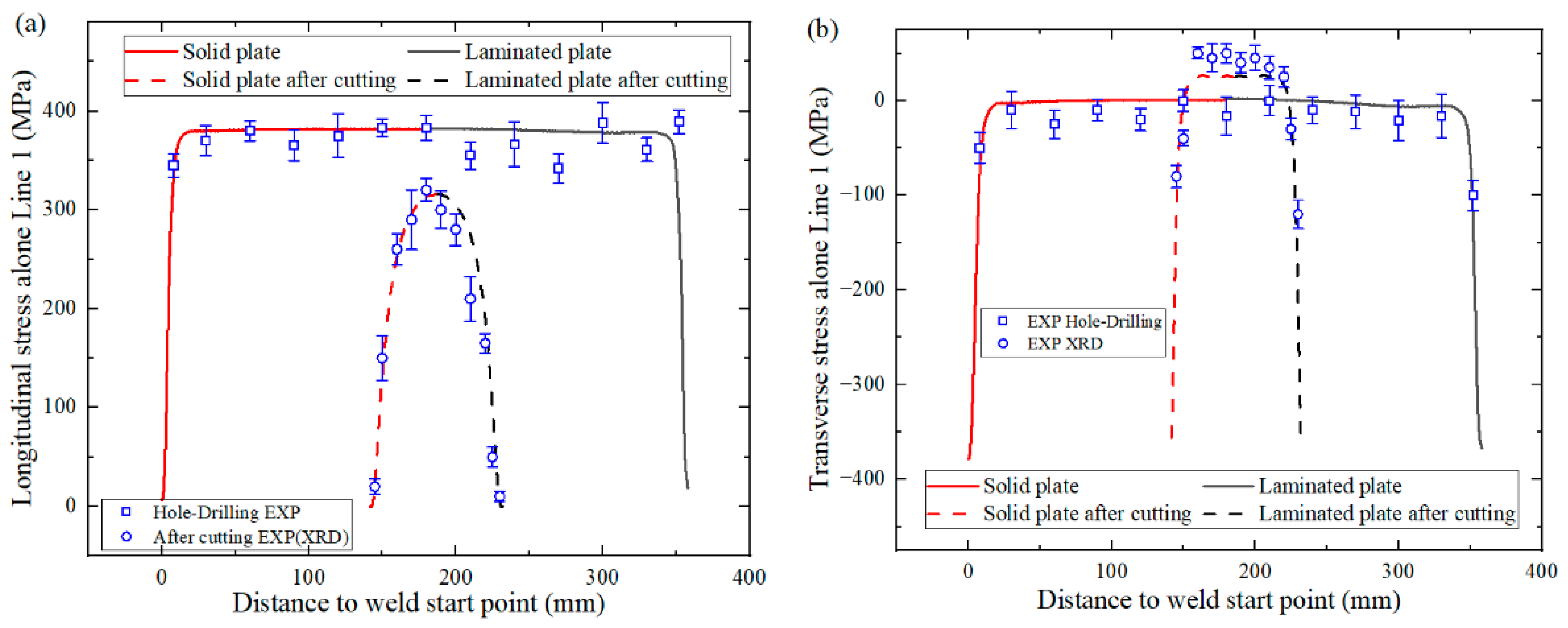
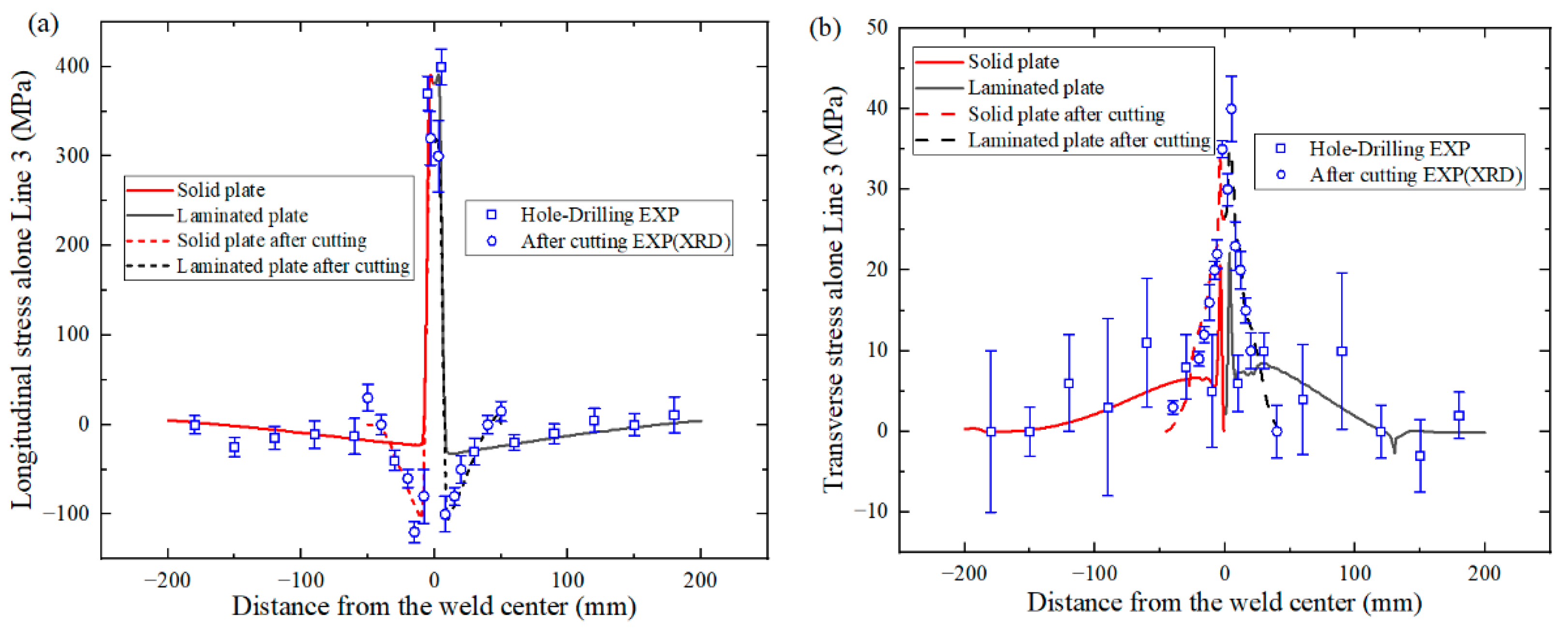
The simulated and measured welding residual stresses of the solid plate and laminated plate are presented in
Figure 11 and
Figure 12. Owing to the spatial symmetry of the residual stress distribution, only half of the measurement results for each plate are shown.
Figure 11a shows the longitudinal residual stress extracted along Line 1. A stress-relaxation zone is observed near both ends of the weld seam, located approximately 12 mm from the plate edges, which is associated with edge effects. The longitudinal stress decreases to nearly zero at the ends, while it remains relatively stable in the central region at about 380 Mpa.
Figure 11b presents the transverse residual stress along Line 1. A pronounced compressive region appears within roughly 20 mm from both seam ends; outside this zone, the transverse stress is tensile but remains below 5 Mpa. Overall, the transverse residual-stress field is nearly self-equilibrated, and the integral of transverse stress along the coordinate direction approaches zero.
No significant difference is observed between the solid and laminated plates in terms of the residual-stress distributions along Line 1. This indicates that, along the weld direction, residual-stress formation is governed primarily by the localized, highly non-uniform thermal cycle (i.e., the near-field temperature gradients and cooling conditions) imposed by the moving heat source and subsequent heat dissipation, rather than by global stiffness variations introduced by the laminated architecture. In other words, under identical heat-source parameters and heat-transfer boundary conditions, the thermal driving field dominates the residual-stress level along the seam, while stiffness non-uniformity plays a secondary role for this specific stress component and extraction path.
Figure 12a presents the longitudinal residual-stress distribution along Line 3. The tensile longitudinal residual stress is mainly concentrated within the weld seam and within approximately 15 mm on both sides, while compressive stresses develop in the remaining regions to satisfy force equilibrium. The integral of longitudinal residual stress along the transverse direction is approximately zero, indicating a self-equilibrated stress state. Owing to the highly localized laser heat input and the resulting steep thermal gradients, the thermally affected zone is narrow and the residual-stress field is correspondingly concentrated. The maximum longitudinal residual stress reaches approximately 385 Mpa for both the solid and laminated plates, and the overall distribution patterns are similar. Although the laminated plate shows slightly higher compressive levels in certain regions, the difference between the two plates is limited.
Figure 12b shows the transverse residual-stress distribution along Line 3. Both the XRD and hole-drilling measurements exhibit relatively large scatter, mainly because the transverse residual stress is much smaller than the longitudinal component, whereas the experimental uncertainty of both methods in the present study remains on the order of 10 Mpa. In addition, the presence of columnar grains in the weld region makes accurate XRD measurement more difficult. Nevertheless, the overall experimental trends are consistent with the simulation results, and the absolute deviations are generally within 10 Mpa, indicating acceptable agreement between experiment and simulation. The transverse component is much smaller than the longitudinal one, and a noticeable stress drop occurs at the weld center. This behavior can be attributed to the relatively weaker transverse restraint and to partial stress relaxation associated with welding-induced angular/bending distortion, which modifies the constraint state during cooling. The solid and laminated plates exhibit consistent distribution trends, with only minor numerical differences.
Although the solid and laminated plates exhibit highly similar residual-stress distributions, their welding-induced distortions differ markedly, as shown in
Figure 13.
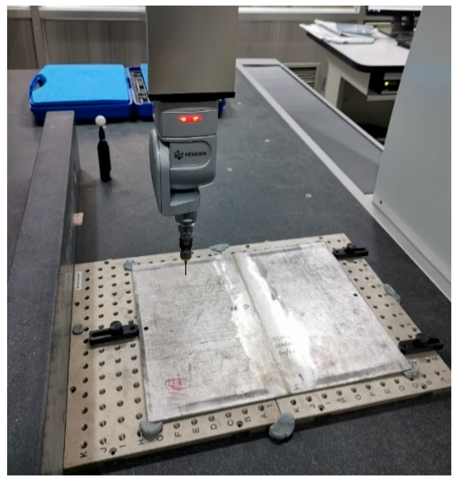
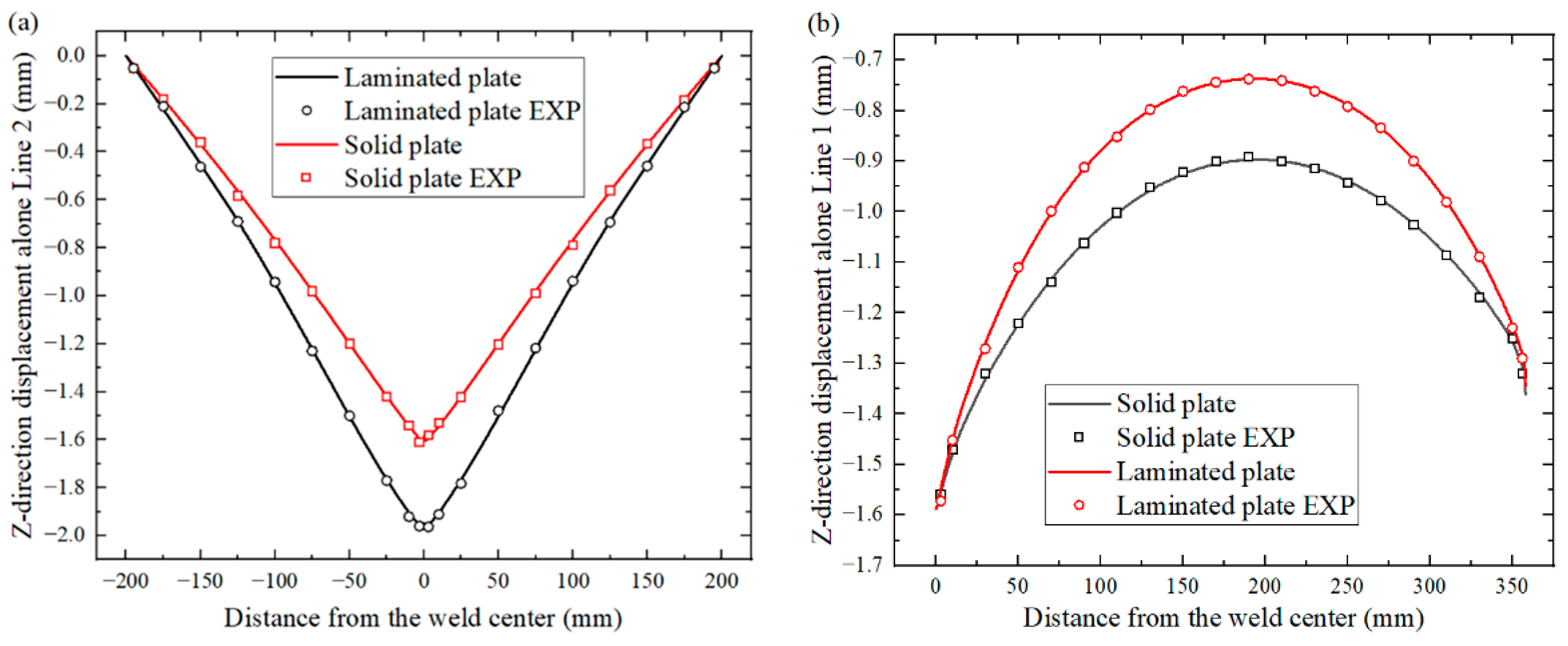
Figure 13 compares the post-weld out-of-plane (Z-direction) displacement profiles extracted along two representative lines (Line 1 and Line 2). The finite-element predictions agree well with the experimental measurements (EXP), supporting the credibility of the coupled analysis.
Figure 13a shows the Z-direction displacement along Line 2. The deformation profile is approximately symmetric about the weld center and presents a characteristic “V” shape [
31]. The maximum displacement occurs near the weld center and decays rapidly with increasing distance, approaching zero in the far field. This deformation mode is typical for thin-plate welding and can be interpreted as the macroscopic manifestation of the localized thermal cycle: steep temperature gradients and heat-flow-driven non-uniform expansion/contraction generate an imbalance between compressive and tensile plastic strains across the weld region, which accumulates as angular distortion during cooling. Under identical heat input and overall dimensions, the laminated plate exhibits significantly larger angular distortion than the solid plate; the maximum displacement at the weld center increases from approximately 1.6 mm to about 2.0 mm.
Figure 13b presents the Z-direction displacement along Line 1, reflecting the overall bending deformation of the plate. Line 1 corresponds to the weld zone, where plastic strain is concentrated. Owing to the difference in weld-pool width between the top and bottom surfaces, the longitudinal contraction during cooling becomes non-uniform through the thickness, leading to the maximum bending deformation in this region. Under the same boundary conditions, the laminated plate shows more pronounced deflection than the solid plate. These results indicate that welding distortion is not determined by residual stress alone. Even when the thermally induced residual-stress patterns are similar, differences in structural stiffness and the associated restraint redistribution during the heating and cooling process can still result in distinct deformation responses. Therefore, the stiffness non-uniformity introduced by the laminated configuration plays a dominant role in the observed distortion difference.
4.3. Plastic Strain Distribution
According to inherent strain theory, welding distortion is primarily governed by the spatial distribution of non-recoverable inelastic strain, with plastic strain being the dominant contributor in fusion welding. Because plastic strain is generated under a highly localized thermal cycle, the final deformation pattern can be viewed as an integrated response to the heat-transfer-driven temperature gradients and the associated restraint conditions.
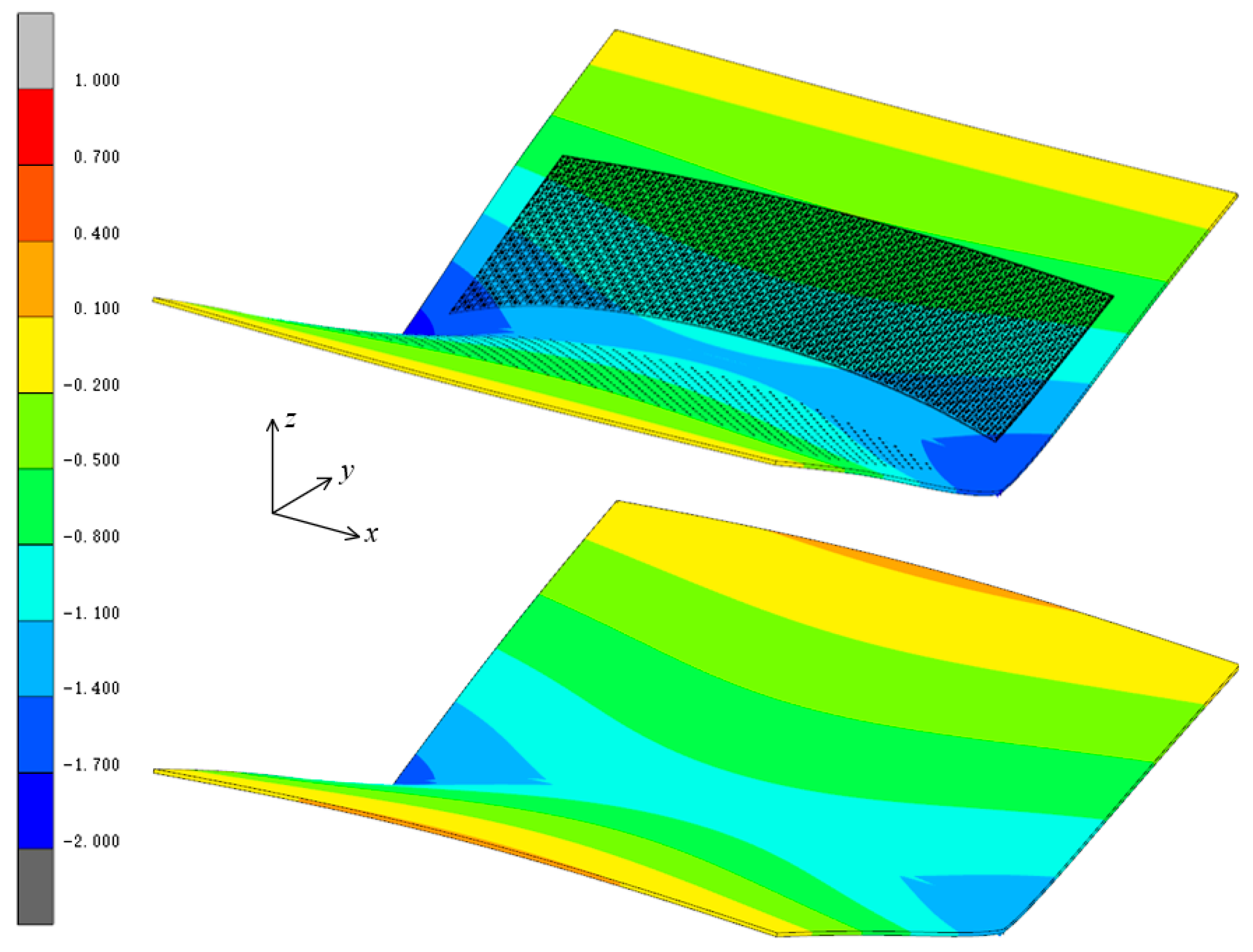
Figure 14 presents the post-weld out-of-plane (Z-direction) displacement contours of the laminated and solid plates, with a magnification factor of 20 applied for clarity.
The global deformation modes of the laminated and solid plates are highly similar, and both exhibit the characteristic angular-distortion pattern typical of thin-plate laser welding. The representative displacement profiles extracted along selected lines (
Figure 13) further confirm the similarity in deformation shape between the two plates. This consistency suggests that the overall spatial pattern of the plastic-strain field is also broadly comparable, while differences are expected mainly in magnitude and local concentration due to the stiffness non-uniformity introduced by the laminated configuration.
To further clarify the specific differences in plastic strain under identical heat transfer conditions, the distributions of plastic strain were extracted, as shown in
Figure 15 and
Figure 16.
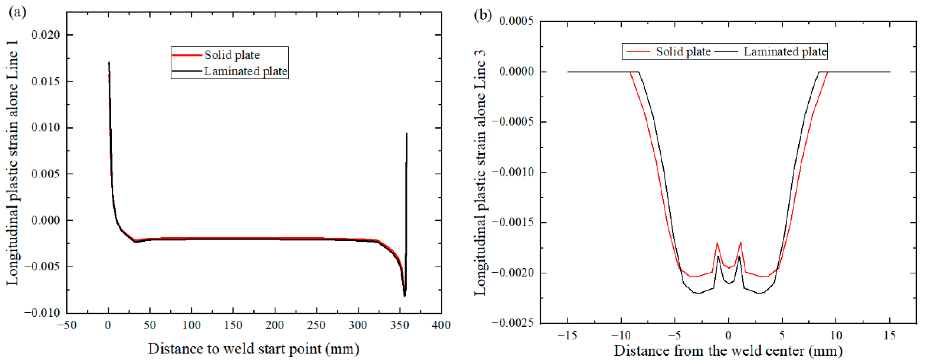
Figure 15a presents the post-weld longitudinal plastic strain extracted along Line 1. The laminated and solid plates exhibit similar overall trends. A pronounced positive peak appears near the weld start, followed by a rapid drop into a relatively stable plateau region; another abrupt variation occurs close to the weld termination. These end effects are consistent with the transient thermal boundary at the weld start/stop, where the local thermal cycle (and thus thermal expansion–contraction mismatch) differs from that in the steady-travel segment. Within the plateau region, the laminated plate shows slightly larger absolute longitudinal plastic strain than the solid plate.
Figure 15b shows the local longitudinal plastic-strain distribution along Line 3 with the weld center as the origin. The plastic strain is strongly localized around the weld center and decays rapidly with distance, approaching zero beyond approximately 10 mm from the centerline. The narrow affected region reflects the highly concentrated laser heat input and the resulting steep temperature gradients. Although the curve shapes for the two plates are similar, differences appear in the depth of the concave region and in the local details near the weld center. The laminated plate exhibits larger absolute plastic-strain values, while the affected zone is relatively narrower, indicating a more localized longitudinal plastic response under the non-uniform stiffness condition.
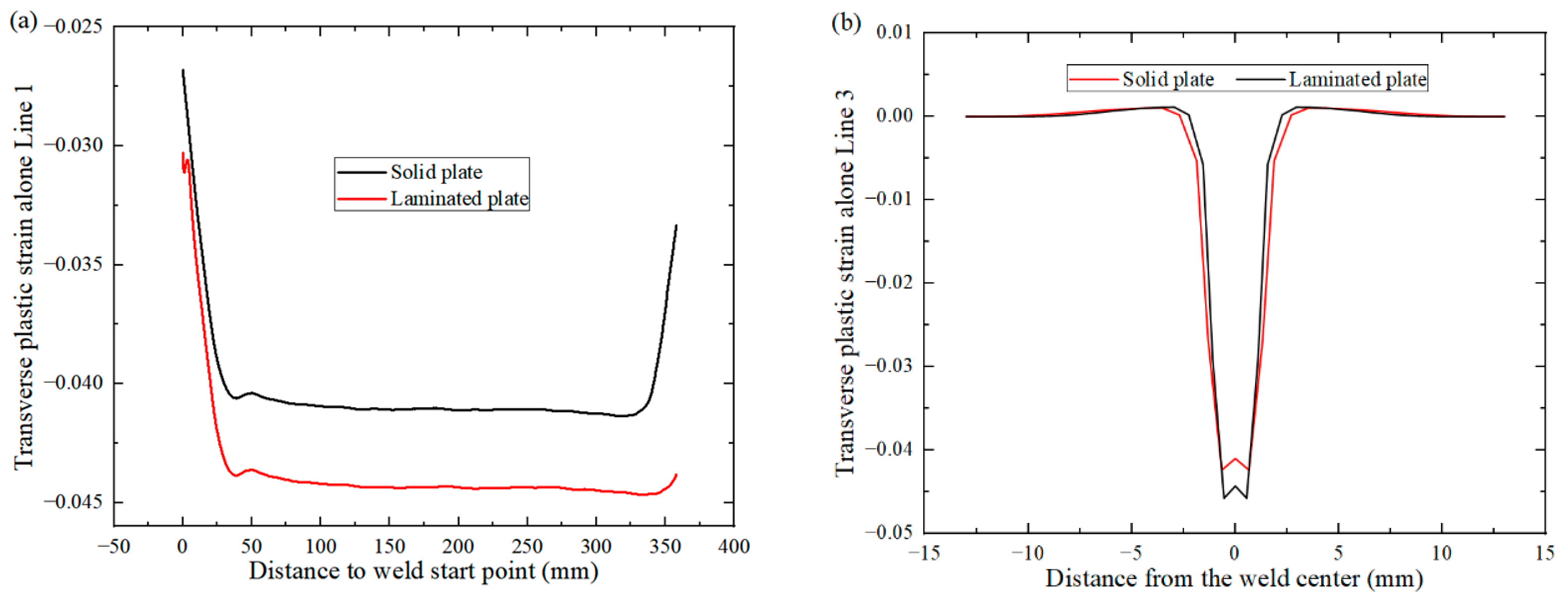
Figure 16a presents the transverse plastic-strain distribution along Line 1. Both the laminated and solid plates show rapid variations near the weld start and termination, followed by a relatively stable plateau over the long central segment. This start/stop behavior is consistent with the non-steady thermal boundary at the beginning and end of welding, where the transient heat input and heat dissipation conditions differ from those in the steady-travel region. In the plateau region, the laminated plate exhibits larger absolute transverse plastic-strain values than the solid plate.
Figure 16b shows the local transverse plastic-strain distribution along Line 3 with the weld center as the origin. A sharp negative valley appears near the weld center, and the strain rapidly recovers toward zero away from the weld, becoming negligible beyond approximately 12 mm from the centerline. The strong localization reflects the highly concentrated laser heat input and the resulting steep temperature gradients. Although the overall curve shapes of the two plates are similar, differences are evident in the valley depth and local curvature near the weld center. The laminated plate develops a larger peak magnitude of transverse plastic strain, while the affected zone is relatively narrower.
Overall, the transverse plastic strain is significantly larger than the longitudinal component, consistent with the different restraint levels in the transverse and longitudinal directions during welding. By comparing
Figure 15 and
Figure 16, it is evident that the laminated and solid plates share broadly similar spatial patterns of plastic strain, whereas clear differences exist in magnitude and effective distribution width. The laminated plate generally exhibits larger plastic-strain magnitudes within a narrower affected region. Under an identical thermal loading baseline (same heat-source parameters and heat-transfer boundary conditions), these differences can be attributed to the stiffness-dependent restraint redistribution, which modifies how the heat-transfer-driven thermal strains are constrained and hence alters the evolution and spatial distribution of plastic strain.
4.4. Plastic Strain Evolution During Thermo-Mechanical Coupling
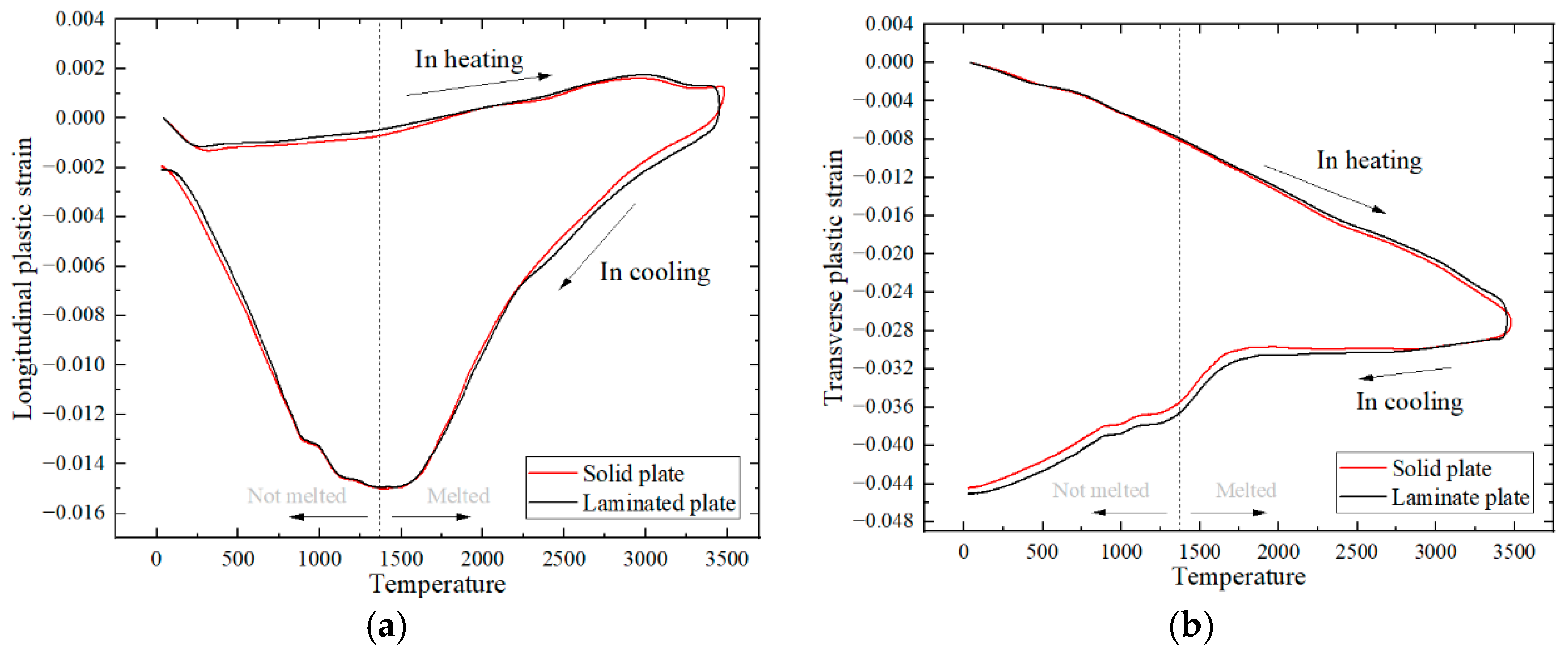
To further clarify the roles of heat transfer and structural stiffness in governing plastic strain evolution, the temperature-dependent evolution paths of plastic strain during a representative thermal cycle were extracted, as shown in
Figure 17.
Figure 17 presents the plastic strain–temperature evolution for the solid and laminated plates during a representative thermal cycle. The arrows indicate the heating and cooling stages. The vertical dashed line denotes the melting boundary temperature (1370 °C), separating the non-melted and melted regimes.
Figure 17a shows the evolution of longitudinal plastic strain. During heating, the longitudinal plastic strain is slightly negative at low temperatures and increases gradually with temperature, becoming positive at elevated temperatures. During cooling, the minimum longitudinal plastic strain appears near the melting boundary temperature; as temperature decreases further, the strain partially recovers and approaches a small negative value at room temperature. The laminated and solid plates exhibit similar trajectories, while the laminated plate maintains slightly higher strain levels throughout the cycle.
Figure 17b illustrates the transverse plastic-strain evolution. During heating, the transverse plastic strain increases monotonically with temperature. During cooling, it continues to increase and reaches its maximum magnitude after complete cooling. The transverse component is markedly larger than the longitudinal one, and no sign reversal or apparent recovery is observed.
These directional differences arise from the distinct constraint paths under a highly localized welding thermal cycle. Along the longitudinal direction, each material point undergoes a sequential heating–cooling history as the moving heat source passes, and the shrinkage of previously heated regions imposes tensile effects on the subsequently heated material, enabling partial redistribution and recovery of longitudinal plastic strain during cooling. In contrast, the transverse direction is predominantly constrained by the adjacent unmelted material on both sides of the weld, and the lateral restraint under steep temperature gradients promotes the accumulation of compressive plastic strain. In addition, welding-induced angular distortion modifies the transverse constraint state during cooling, further intensifying transverse plastic-strain accumulation and leading to larger transverse magnitudes.
4.5. Influence of Structural Stiffness on the Thermo-Mechanical Process
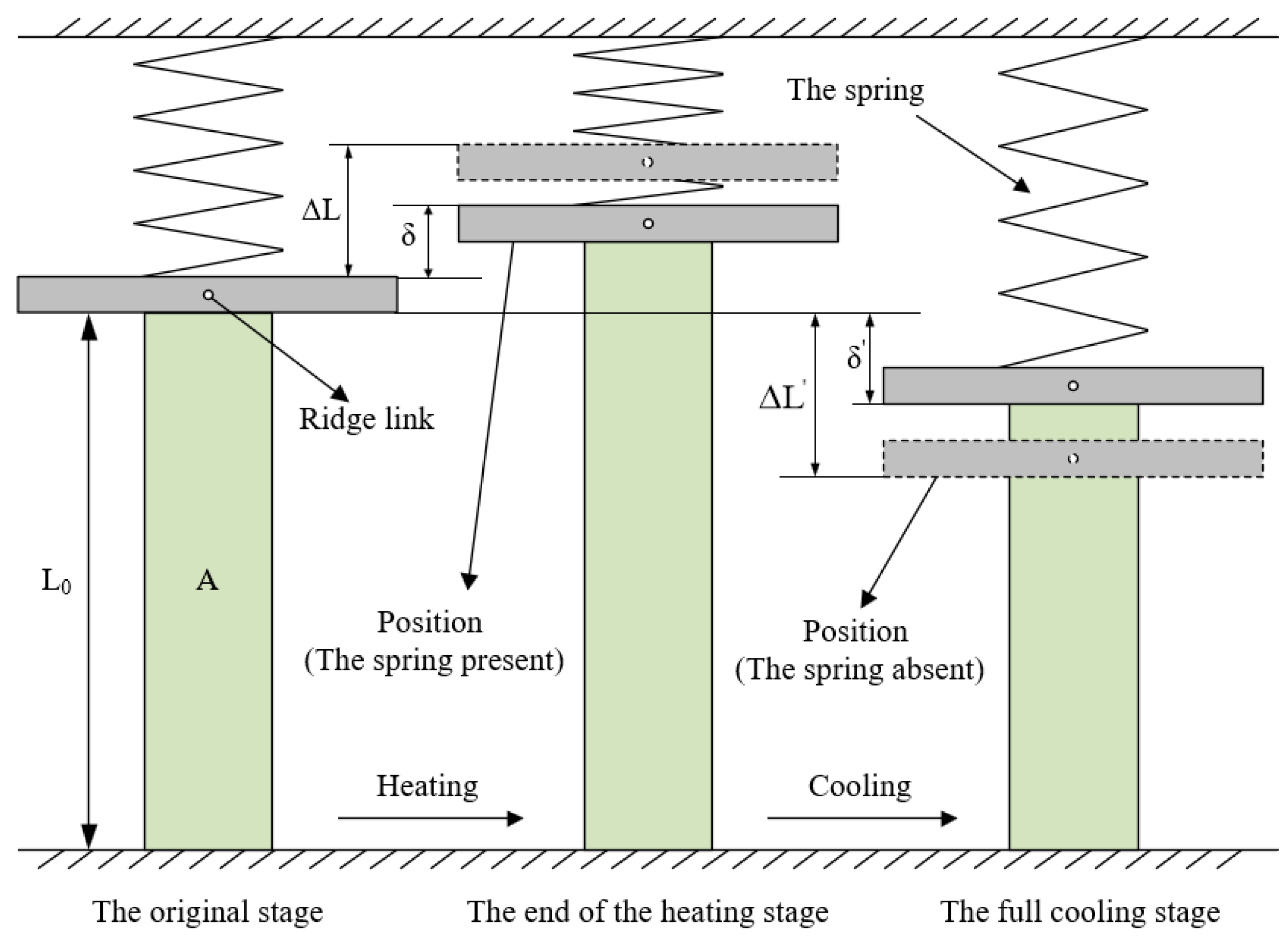
To provide a more quantitative interpretation of the plastic strain evolution described above, a stiffness–bar–spring model was developed, as illustrated in
Figure 18. The model is intended to describe the evolution of longitudinal plastic strain during heating by representing the restraint effect of the surrounding base material with an equivalent spring.
In the proposed stiffness–bar–spring model, the two ends of the bar are assumed to be rigidly connected through an end link, which enforces displacement compatibility. The material is assumed to be temperature-independent for analytical simplicity, and an elastic–perfectly plastic constitutive law is adopted, such that the stress remains constant once the yield strength is reached. Owing to the sufficiently large longitudinal restraint, the bar ends are further assumed to remain horizontal during deformation. The coefficients of thermal expansion, yield strength, and elastic modulus are denoted by α, σs, and E, respectively. The stiffness of the equivalent spring is denoted by K.
As illustrated in
Figure 18, during the heating stage, if no spring restraint is present, the free thermal elongation of the bar is
where
L0 is the initial length of the bar,
α is the coefficient of thermal expansion, and Δ
T is the temperature increment.
When the spring restraint is introduced, force equilibrium must be satisfied between the bar and the spring. The spring force equals the internal axial force in the bar, leading to:
where
K is the stiffness of the equivalent spring,
E is the elastic modulus,
A is the cross-sectional area of the bar, and
δ is the restrained displacement induced by the spring.
Solving for
δ, the restrained displacement is obtained as
The compressive strain in the bar under restrained thermal expansion is:
When the temperature increase is sufficiently large such that yielding occurs in the bar, the compressive strain reaches the yield strain. Therefore,
from which the temperature rise required to initiate yielding is obtained as
Equation (13) indicates that as the stiffness
K increases, the required temperature increment for yielding decreases. In other words, stronger restraint promotes earlier yielding. This explains why the solid plate, which exhibits higher effective stiffness, develops a wider plastic zone, consistent with the differences observed in
Figure 15 and
Figure 16.
Compared with the solid plate, the laminated plate contains numerous non-uniformly distributed internal channels, which reduce its overall structural stiffness and consequently lower its resistance to deformation. In the model shown in
Figure 18, this stiffness reduction is reflected by a decrease in the equivalent external restraint parameter
K. During the analysis, both the laminated plate and the solid plate were subjected to the same thermal input and surface heat-flux distribution. According to Equation (13), a smaller
K leads to a higher critical temperature for yielding during the thermal expansion stage. In other words, weaker restraint delays yielding and tends to confine plastic deformation to a narrower region, whereas stronger restraint promotes yielding over a wider zone. This explains why the plastic strain in the laminated plate is more concentrated near the weld seam, as shown in
Figure 15b and
Figure 16a.
After complete cooling, the stress in the weld region is assumed to approach the yield level. From force equilibrium:
The corresponding elastic recovery of the bar is
The residual compressive plastic strain is therefore expressed as:
Equation (16) shows that the peak residual compressive plastic strain decreases with increasing stiffness
K. Since the solid plate has a larger effective stiffness than the laminated plate, its final compressive plastic strain remains lower. This theoretical prediction is consistent with the evolution results shown in
Figure 17. Overall, the proposed model successfully captures the relationship between welding-induced plastic strain and external stiffness, and qualitatively clarifies how the external stiffness parameter
K influences the magnitude of plastic strain. It therefore provides a useful mechanistic interpretation and reference for understanding the evolution of plastic strain during the thermo-mechanical process.




 ,
,