Review

Power Consumption Analysis of the Power System in a Gigafactory: A Review

Department of Energy “Galileo Ferraris”, Politecnico di Torino, 10129 Torino, Italy
*
Author to whom correspondence should be addressed.
Energies 2026, 19(5), 1345; https://doi.org/10.3390/en19051345
Submission received: 26 January 2026 / Revised: 24 February 2026 / Accepted: 4 March 2026 / Published: 6 March 2026

Abstract

Recent decades have seen substantial growth in the demand for lithium-ion batteries (LIBs); as a result, the number of gigafactories is increasing. The power systems of these gigafactories are the most important parts of these installations, as they are directly responsible for energy efficiency, operational cost, and sustainable growth of the LIB industry. This necessitates the need for comprehensive studies of power consumption in a gigafactory during the LIB manufacturing process. This paper presents a detailed review of the state-of-the-art of different parts and components of power systems in gigafactories, and power consumption estimation during cell production. This research analyzes the existing components of a power system, including power sources, different power distribution mechanisms, various power equipment, thermal management strategies, failure analysis methods, and several technologies for regenerative functions. The analysis of the above-mentioned components, systems, and technologies will enable us to understand the cumulative power consumption profile of the gigafactory, including the power consumption at each step of the production process, for normal non-production operations, like powering and lighting the facility, and for the complex and highly sophisticated power distribution system. The outcomes of this research paper highlight the importance of an optimized power system for the gigafactory, with maximum possible efficiency and minimal power losses during transmission, distribution, operational stages, and the cell formation process. This paper also helps to understand the shortcomings in existing systems and technologies, suggests improvements, and provides targets for future research directions.

1. Introduction

Large-scale manufacturing facilities for lithium-ion batteries (LIBs) with a total manufacturing capability of more than 1 GWh are generally referred to as gigafactories. These gigafactories are fundamental to meeting the ever-increasing demand for LIBs in a rapidly digitalizing world. The production of LIBs has been projected to increase about sevenfold to reach 2200 GWh by 2030 [1]. These gigafactories consume a massive amount of electrical energy for LIB production, particularly during the cell formation process. For instance, the manufacturing of a 24 kWh battery pack requires 16.31 MWh [2,3]. This makes an energy-efficient power system a critical necessity for a modern, reliable, and sustainable gigafactory [4]. This research analyzes power consumption during cell manufacturing. The main goal is to identify different power consumption patterns and trends, establish key areas of power losses, and propose improvements to enhance the energy efficiency of the power system for future research directions.
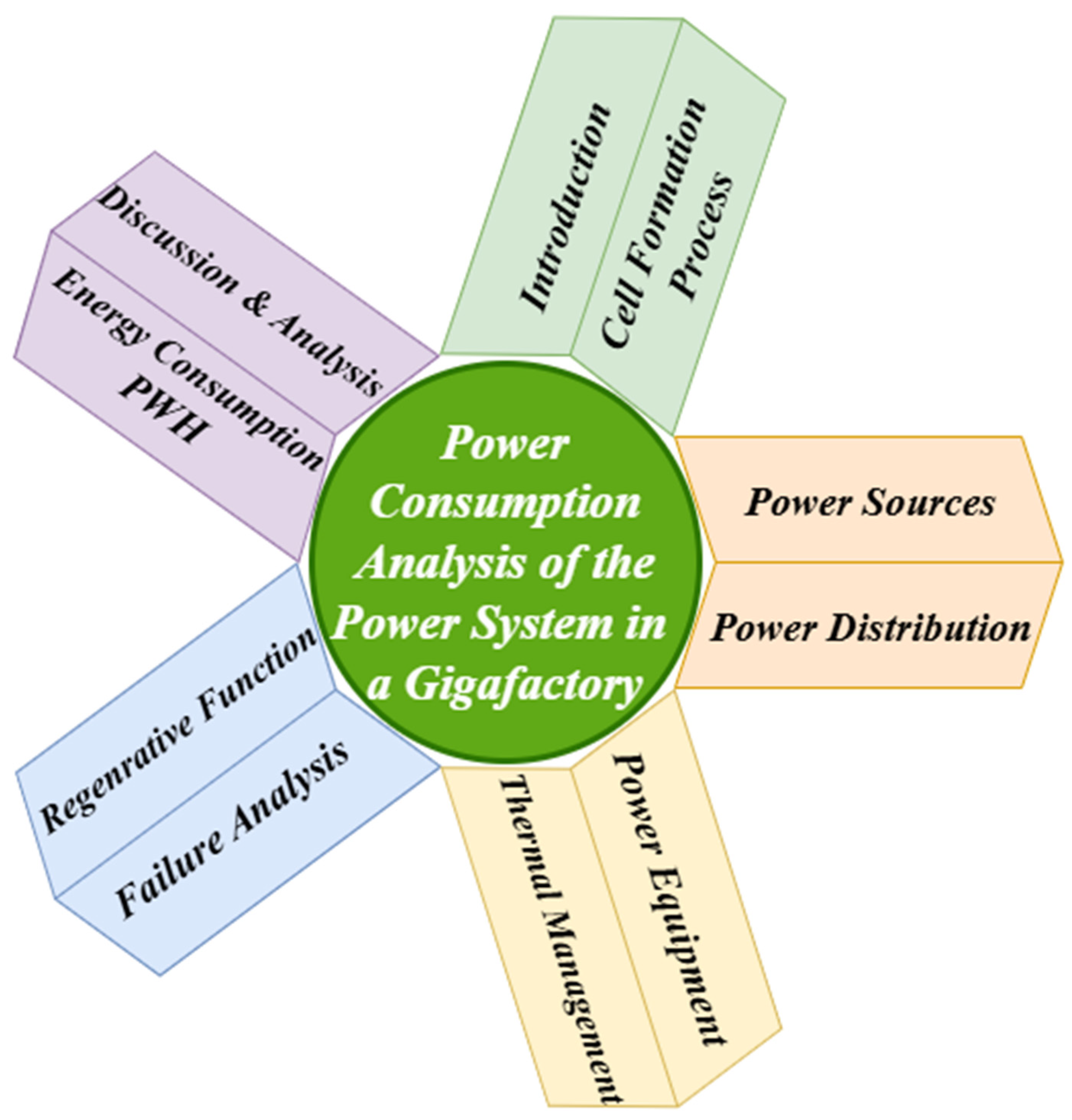
Figure 1 provides brief information about the key elements of the power system analysis in a gigafactory. Historically, power consumption analysis was overlooked. But in recent times, with a growing focus on sustainable and energy-efficient power systems for industrial plants, the field’s importance has increased, and the available literature has expanded significantly. This review paper explains the critical components and methodologies for power consumption analysis in gigafactories. These include power sources, distribution systems, power equipment, thermal management systems, failure analysis, regenerative functions, and other critical energy-consumption metrics of cell formation systems.
Exploring the diversification of the power sources and their integration into the gigafactory’s existing power systems is fundamental. An increase in the production of renewable energy sources, such as solar and wind, may support the gigafactories’ reliance on the traditional grid power. The integration of renewable power into the existing power systems of industrial plants results in considerable reductions in operational costs and carbon emissions, as highlighted in [5]. For example, Tesla’s gigafactory in Nevada has installed solar panels on site and uses this renewable power in combination with grid power, which has reduced its dependency on fossil fuels and other non-renewable power sources and increased its sustainability [6].
The thermal management of a power system is crucial for preventing equipment from overheating and maintaining optimal operating conditions [7]. A large amount of heat is generated by the electrical equipment in a gigafactory power system and released into the surrounding environment. These thermal loads have been effectively reduced by using a liquid cooling system in combination with heat exchangers in industrial plants. The advantages of this cooling method have been explained in [8]. In addition to cooling liquids and heat exchangers, improvements in the design and use of advanced materials for cooling systems and heat sinks can effectively enhance cooling system efficiency by managing the generated heat [9,10].
Optimization and reduction in operational costs of the industrial plant can be achieved with regenerative functions used as a power-saving measure. Such regenerative systems are particularly advantageous in high-power applications, where frequent braking and acceleration cycles occur. Regenerative systems can effectively be used to recover and reuse heat energy that would otherwise be lost as waste heat [11]. Integration of regenerative systems into existing industrial processes can result in significant energy savings and a reduction in operational costs [12]. Another important factor for power system analysis is understanding and mitigating power system failures. Mitigation of these failures is critical for maintaining an uninterruptible power supply (UPS) and the smooth functioning of gigafactories (or any other industrial plant). Commonly identified failure points in an industrial plant’s power system are switches, transformers, and power transmission lines, as explained in [13]. The use of predictive maintenance and real-time monitoring is necessary to prevent power failures [14]. It is vital to avoid or decrease power failures in the power system through the implementation of robust maintenance schedules and high-quality switching and control components [15].
For an effective and efficient analysis of the power system in the gigafactory, per-watt-hour power consumption is considered a critical parameter. Comparison of different power consumption metrics from several gigafactories can help us identify best practices for power saving and also indicate the critical areas for improvement [16]. Power management systems, specific operational practices, and advanced technologies are important factors for enhancing power efficiency. As an instance, the overall power consumption can be considerably reduced by implementing the strategy of optimized production schedules and energy-efficient lighting systems in industrial plants [17].
The reminder of the paper is as follows: Section 2 presents the cell formation process; Section 3 focuses on power sources; Section 4 analyses the power distribution system, including earthing systems; Section 5 focuses on power equipment for the cell formation process; Section 6 describes all the thermal management approaches; Section 7 covers the generative function; Section 8 covers the failure analysis in gigafactory. All of the above aspects are discussed in Section 10, whereas Section 11 presents the concluding remarks.

2. Cell Formation Process

The most important stage in the gigafactory of LIBs is the cell formation process. This process electrochemically activates newly manufactured LIB cells. The LIB cells are electrochemically activated through rigorous and continuous charging and discharging cycles. Different charging and discharging topologies and C-rates are used to achieve desired characteristics. This makes the cell formation process one of the most energy-intensive stages in the gigafactory, consuming more power compared to any other stage in the LIB manufacturing process.
The formation area of the cell manufacturing facility consists of formation towers made up of chambers or individual racks with an independent control channel for each cell in both topologies [18].
The power system required for the cell formation process comprises numerous power equipment, including battery testers, AC/DC and DC/DC converters, cell chargers, and monitoring and protection systems. The performance of the cell formation process can be improved by using higher efficiency and innovative power systems.
Cell formation includes important processes, critical for normal cell operation, including Solid Electrolyte Interphase (SEI) formation, Cathode Electrolyte Interphase (CEI) formation, and structural changes in active materials [19,20]:
  • The cell formation process is responsible for the formation of the SEI layer on the surface of the anode, so that direct contact between the anode and electrolyte can be avoided during normal cell operation [19].
  • Just as SEI is formed at the anode layer, CEI is formed at the cathode surface, and generally the thickness of the CEI layer is less than the SEI layer [21].
  • Cell formation process is also responsible for establishing stable electrical contact between the electrolyte and the active materials [22].
The target end of the cell formation process is according to the parameter called Columbic efficiency (CE): the cell formation process is thought to be completed when the value of CE reaches 100% [19].
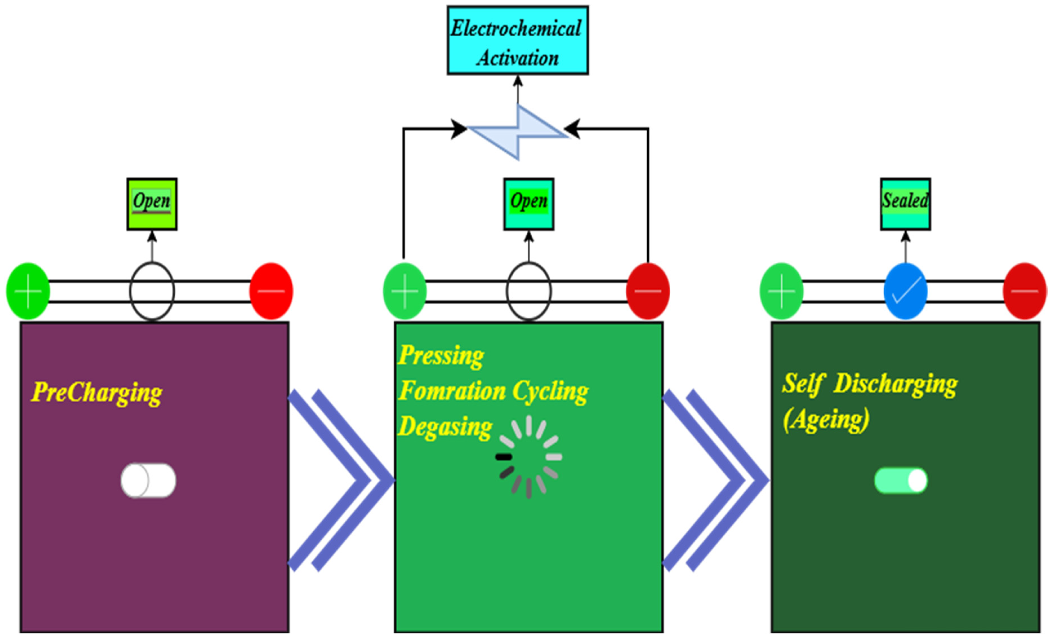
Figure 2 shows the flowchart of the critical stages in the cell formation process of LIBs. These stages are explained in the following paragraphs. During the first stage (pre-charging), the newly manufactured LIBs are prepared for formation cycling, leaving an open hole at the top of the cell. The cells are charged to a very low level with very low charging current rates, i.e., (1/20)C [23].
In the second stage (cell assembly), which consists of pressing, formation cycling, and de-gassing, rigorous formation cycles are carried out on these cells under considerable pressure to avoid swelling during the initial charging period. Cells are charged and discharged according to different protocols depending on the charging rates and current and voltage levels. Different chemical materials in the cells produce gases during this charging process, which are sucked out of the cells through the open hole at the top of the cases.
When the formation cycling reaches the desired levels, the third stage (Self Discharging or Aging) starts: after degassing any remaining gases from the cell, the hole is sealed. Then these cells are moved to the shelves for the aging test (self-discharging) to analyze the results of the formation process and the quality of the produced cells.
The cell formation process impacts cell performance and determines the characteristics and performance of parameters such as aging behavior, power capability, energy consumption, cost, and safety.
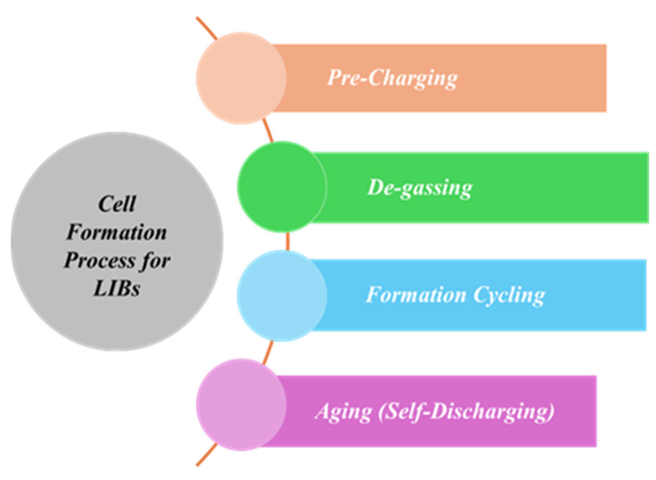
Figure 3 shows the different stages of the cell formation process, consisting of pre-charging, de-gassing, formation cycling, and aging (self-discharging) [24]. The important steps of the cell formation process are briefly explained below:
  • Pre-charging: In the pre-charging phase, the LIB cells are charged for the first time to form the SEI layer on the anode and create a good electrical connection among active materials and electrolyte.
  • De-gassing: In the de-gassing phase, the LIB cells are compressed under suitable pressure to avoid swelling and to remove any gases generated during the pre-charging stage.
  • Formation Cycling: In the formation cycling phase, the LIB cells are charged according to the manufacturer’s guidelines. Usually, charging starts with a lower current and is increased to a certain level set by the cell manufacturer. At this stage, the cells are charged up to 90–95% using constant-current (CC), constant-voltage (CV), or constant-current–constant-voltage (CC-CV) charging techniques. Some novel and innovative protocols are also available as alternatives, such as MS-CC (multi-stage constant-current), PC (pulse charging), CP-CV (constant-power–constant-voltage), and BC (boost charging). However, they are not as widely used as CC-CV. Most gigafactories still prefer the CC-CV protocol due to its obvious advantages. CC-CV offers steady current rates and a simpler power electronics setup. It generates less heat and reduces the power consumption to maintain the cooling of the formation chambers and towers. It also avoids noise and spikes, ensuring a smooth ramp curve during formation cycles. CC-CV provides a higher CE as compared with other protocols and allows virgin cells to be fully charged without overstressing the structure (cell chemistry). Although, when considered in isolation, these innovative formation protocols might show comparatively less power consumption during the formation process, the lifecycle assessment shows that CC-CV still provides the best solution as a cell formation protocol [25]. At the end of the formation cycling stage, the cell case is properly sealed to avoid any leakage.
  • Aging (Self-discharging): In the aging (self-discharging) phase, 90–95 percent charged cells are stored in specially designed cell storage chambers, where these cells undergo the self-discharging process. This is important to understand the quality of newly produced cells.

3. Power Sources

Power sources are critical for a gigafactory producing LIBs, as these power sources ensure the efficient, sustainable, and economical operation of the gigafactory [26]. Usually, a combination of different power sources is used in a gigafactory to manage the huge energy requirements for battery production [27]. This section analyzes common power sources used in a gigafactory (including grid power, renewable energy systems, and backup power supply systems), as well as the characteristics of each power source. In addition to this, it also analyzes the importance of energy storage systems in order to ensure a robust and reliable power supply for the gigafactory [28].
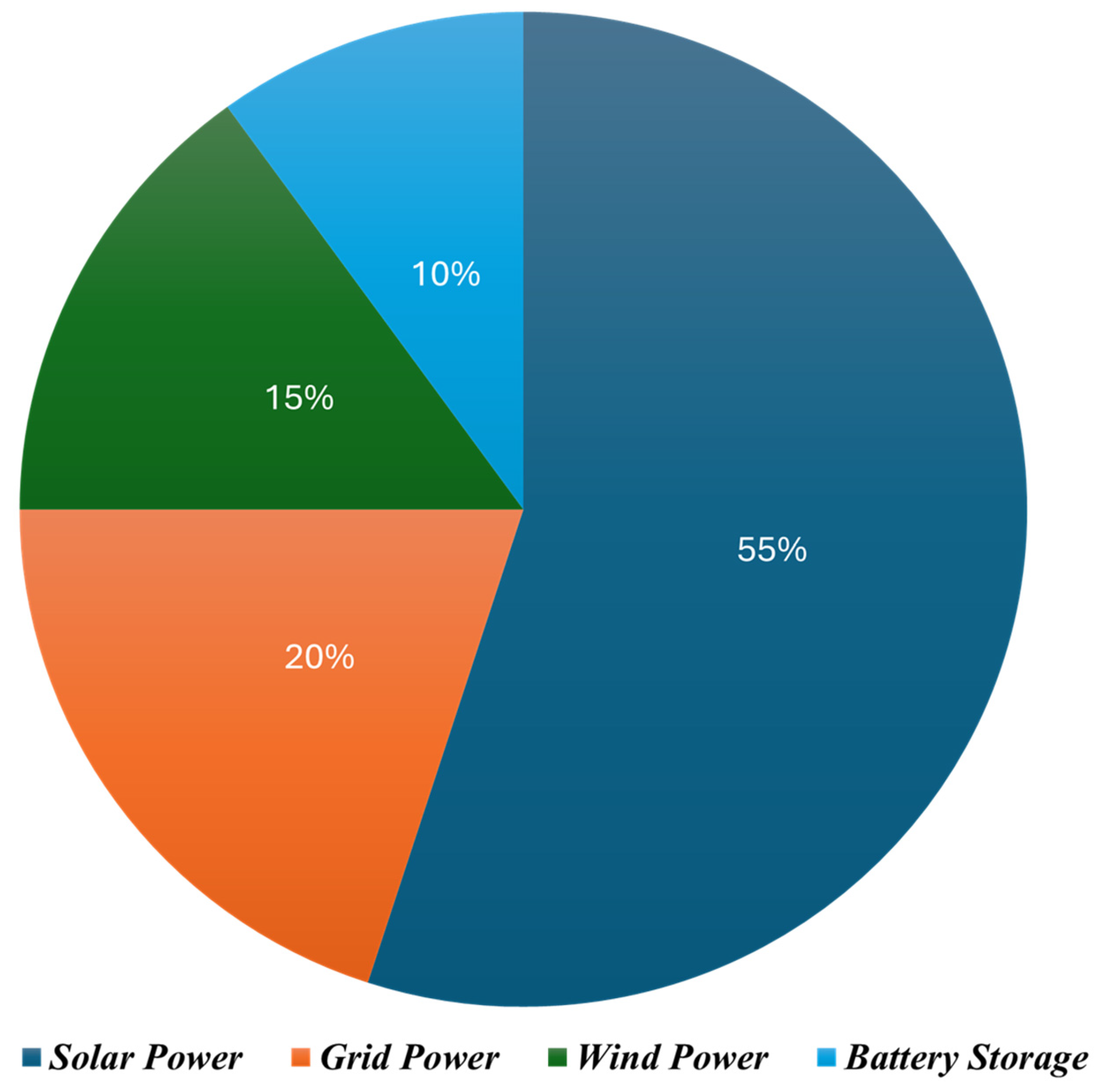
Figure 4 shows the approximate estimation of the percentages of different power sources, combined to meet the power requirement of Tesla’s gigafactory located in Nevada, based on the data published in the 2023 annual impact report [29].
Among these power sources, grid power remains the largest for most gigafactories. To maintain an optimal production process, the grid sources supply continued power to the gigafactory. However, dependence on grid power only has its own drawbacks: it can be expensive due to the change in electricity prices, and it can also face outages due to grid instability [30].
Gigafactories are signing green and stable energy contracts with private electricity providers to manage these risks, including controlling electricity prices and minimizing power outages. These contracts may usually include clauses about demand response programs: in that case, gigafactories agree to minimize their power usage during peak demand hours, and, in return, these electricity suppliers give them reduced prices and other benefits [28].
Gigafactories manufacturing LIB cells require a large amount of stable and uninterrupted electricity. Renewable energy sources play an important role in meeting overall energy requirements. During grid-sourced power outages, these systems can also serve as backup power sources for critical sections of the gigafactory [31]. Apart from supporting power supply, renewable energy sources also help the LIB industry to optimize cost and reduce CO2 emissions during the production process, as reported in the annual reports of famous LIB manufacturers such as CATL and LGES [32,33]. Usual renewable sources adopted in a gigafactory include the following:
  • Solar power: In recent times, gigafactories have begun to install a large number of solar panels on rooftops and empty lands in the surroundings of the main structure, to support grid power, reduce operational costs, and minimize the environmental impact of the gigafactory during manufacturing processes [27].
  • Hydropower: If a gigafactory is located in a suitable location with hydroelectric potential due to the presence of a water reservoir, it can be used to generate hydropower from this water resource. This hydroelectric power can serve as a backup power source to the traditional grid sources. This is quite rare and location-dependent, as gigafactories usually prefer to use on-site power generation to reduce external dependence [34].
  • Cogeneration systems: They are often called combined heat and power (CHP) units as backup power sources. These CHP units generally consist of an electrical generator equipped with the capability to recover and use the generated heat for power generation [35].
    Such CHP systems are quite efficient and useful due to their dual-generation capability, producing both thermal energy and electricity. The electricity is produced by using the extra heat generated during the process of electricity generation [36,37].
    During grid outages, CHPs are usually more efficient and quicker than renewable energy sources as backup power sources. CHPs use natural gas as a generation source. They can also efficiently support primary sources during peak demand hours in case of deficiency in terms of power. However, the main drawback of these CHPs is that they use natural gas as fuel, resulting in increased carbon emissions from facilities [38].
  • Electrical storage systems: Gigafactories need an uninterrupted, balanced, and reliable power supply throughout the manufacturing process. This gives rise to the use of energy storage systems in order to make intermittent energy from renewable energy sources, such as solar and wind [39], consistently available. Gigafactories are established to manufacture LIBs. An efficient and reliable energy storage system can be built by using similar batteries produced in the same gigafactory. These energy storage systems can be used to store additional renewable energy produced during low-demand hours. Later, this energy can be released during peak-demand hours, or at a time when the potential for renewable power generation is low due to atmospheric conditions [27]. The prominent examples of such energy storage systems are Tesla’s Powerpack and Megapack, which are currently being used in Tesla’s facilities and also by other manufacturers around the globe [40].
  • Flywheels: Flywheel technology can be used to store power in the form of kinetic energy. In case of a change in power demand inside the gigafactory, it can provide a rapid response [41,42].
  • Thermal storage systems: To balance the heating and cooling requirements in gigafactories, thermal energy storage systems are used to store extra heat and thermal energy. This technology can be used effectively and reliably in CHP units and conjunction systems (a combination of storage and backup).
All gigafactories must have a sophisticated and robust Energy Management System (EMS) to control the power generated from these diverse power sources. An EMS is used to optimize energy consumption, maximize efficiency, and minimize cost by monitoring real-time energy production, consumption, and storage levels. This system ensures the most suitable available power source is used based on the prediction of energy production and demand. An EMS makes this prediction based on production schedules and environmental constraints [27,43].
Furthermore, a gigafactory requires the implementation of smart grid technologies. They are used for the integration of power from these diverse renewable power sources and storage systems with existing traditional power sources and the grid [44]. This integration of smart grid technology makes the power system more efficient and reliable through the implementation of real-time monitoring, supply and demand balance, and automated control [45].

4. Power Distribution

Gigafactories have quite a complicated power distribution network. The productivity and efficiency of a gigafactory can be considerably enhanced by using an efficient power distribution system. This system ensures that the power is optimally supplied to all the equipment in the factory. It also helps to reduce operational costs by minimizing disruptions and losses during power supply and distribution [46]. This section reports the details of the different components of power distribution systems, including transformers, distribution networks, smart grids, and automation technologies [47].
A.
Power distribution system overview
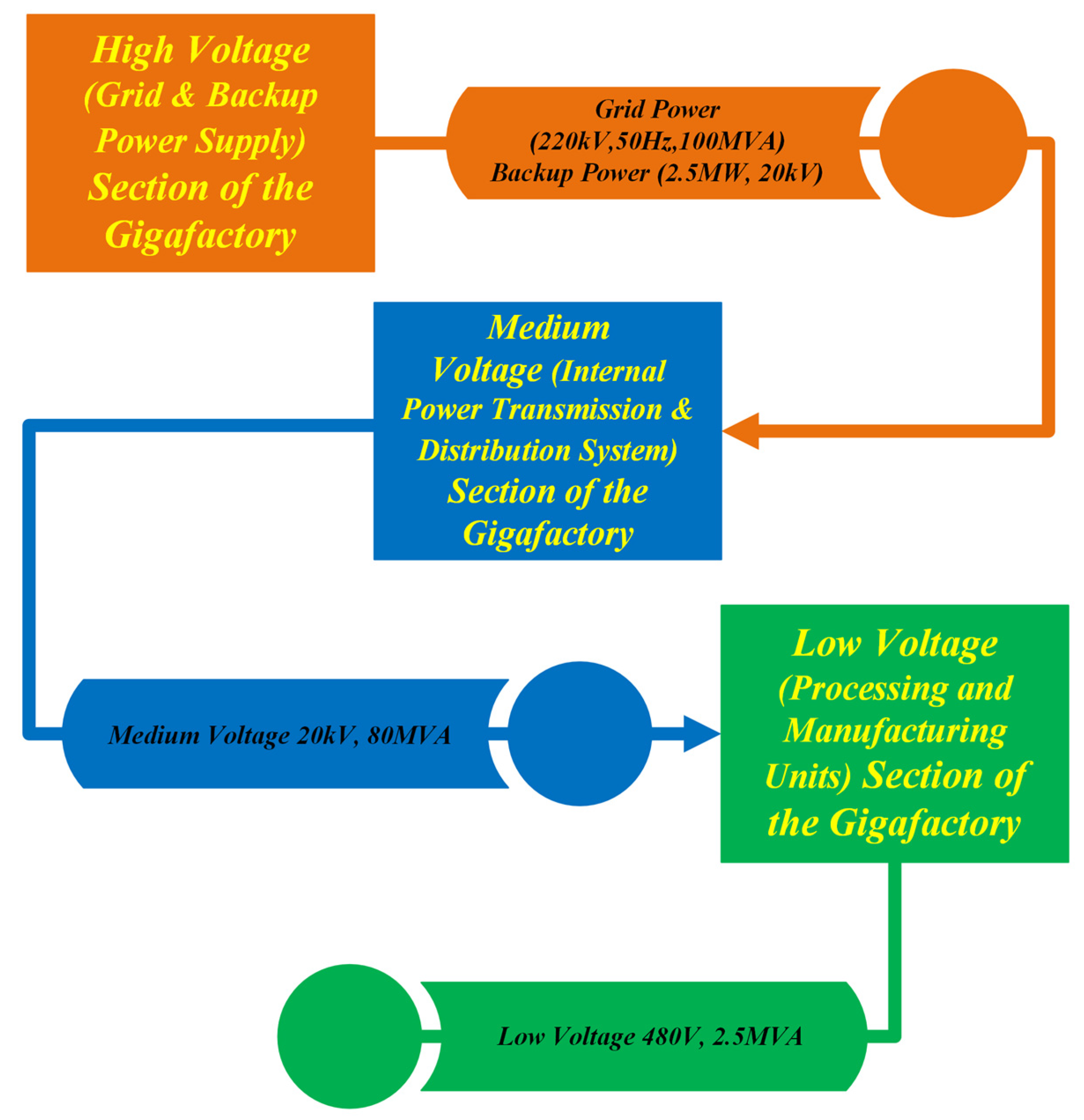
The power distribution system of the gigafactory can be divided into three sections, namely, high-voltage (HV), medium-voltage (MV), and low-voltage (LV) sections.
The HV section represents the power supply from sources (the utility grid and the backup power sources) to the gigafactory. The MV section represents the internal power distribution system, whereas the LV section represents the process unit of the gigafactory where the LIBs are produced. This division of the power distribution system enables us to understand and analyze each section and piece of power equipment. Appropriate safety and protection devices and equipment are designed and proposed according to the voltage level of the particular section. These safety measures and devices protect power equipment and personnel working in proximity to high-voltage equipment.
An overview of the power distribution system in a gigafactory is shown in Figure 5: it can be divided into three sections, namely, the high-voltage (HV) section, medium-voltage (MV) section, and low-voltage (LV) section, based on the operating voltage range of each section.
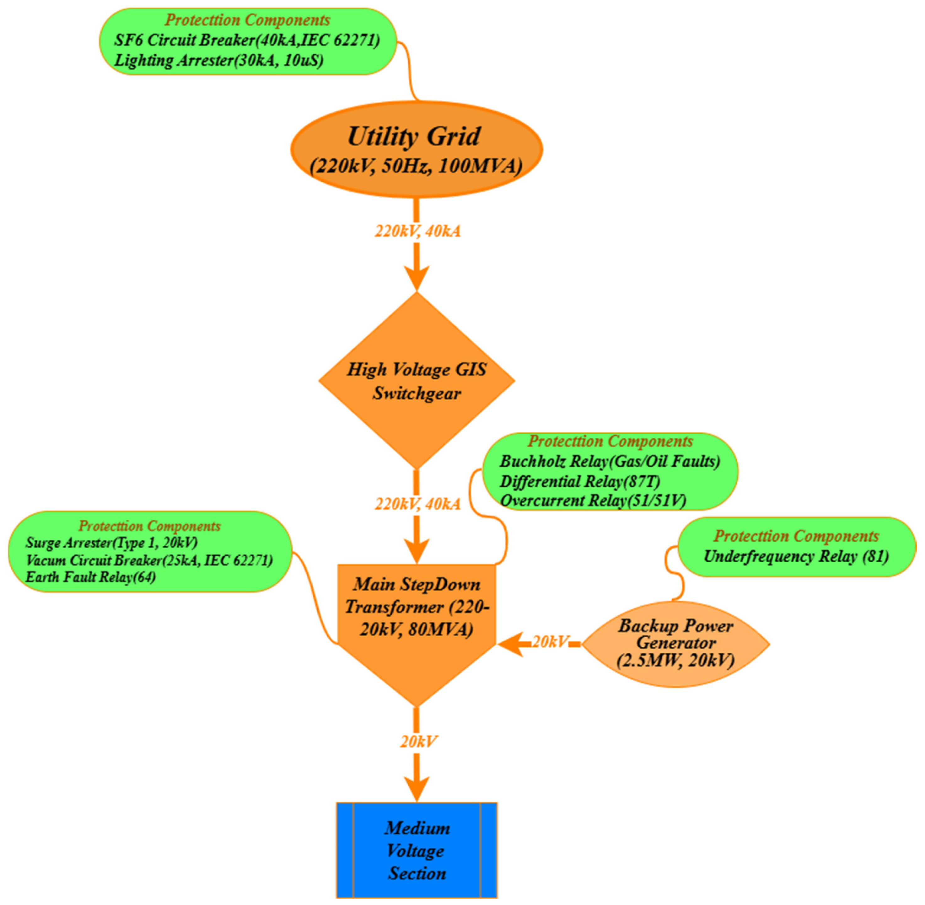
The HV section of the power distribution system is shown in Figure 6; this section generally refers to the power supply section of the gigafactory, consisting of the utility grid supply, backup power systems such as generators, high-voltage switchgears, and the main transformer of the manufacturing facility. This section is generally operated at 220 kV and 100 MVA. Due to these high operational voltage ranges, this section is classified as a high-voltage section. Then, a step-down power transformer is used to step down this power supply to the MV section at 20 kV.
Figure 7 shows the MV section of the power distribution system. This section generally refers to the internal power distribution. It consists of the MV switchgear, a step-down transformer to step down voltage from MV to LV, capacitor banks, renewables, and energy storage systems for additional backup power for the gigafactory.
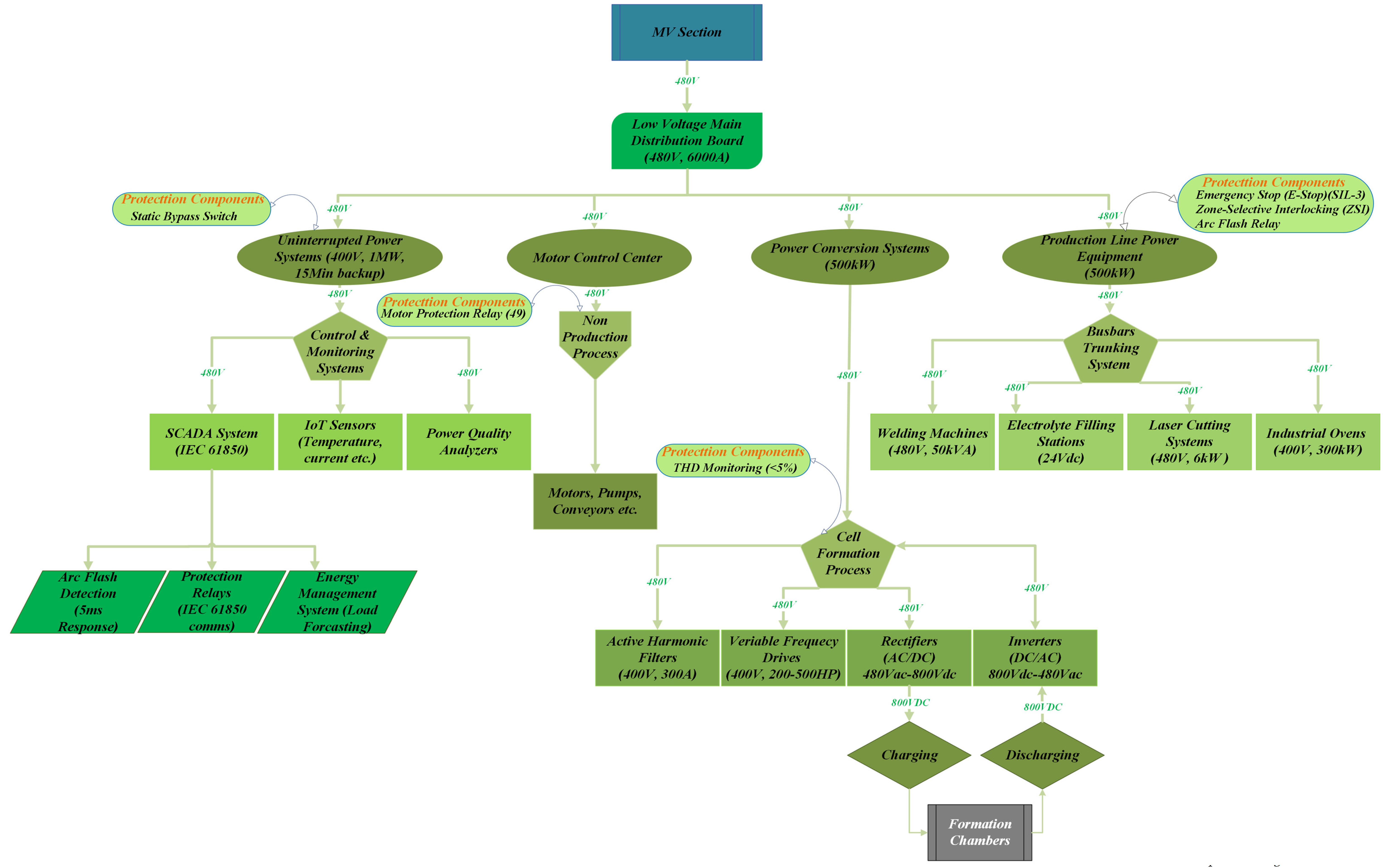
Figure 8 shows the LV section of the power distribution system. This section represents the process section of the gigafactory, where the cell production line is located. It is the most complex section and consists of production line equipment, power conversion systems, motor control systems, uninterruptible power supply systems for the control and monitoring of manufacturing equipment, and formation chambers. The operational voltage range of the LV section extends up to 480 V and 2.5 MVA.
The three sections described above are combined to form a very complex power distribution network (PDN) of a gigafactory. This power distribution network is explained in detail in the following sections of this paper.
B.
Electricity interconnections and protections
Generally, electricity is supplied to the gigafactory at an HV level from the electricity grid. So, this voltage is stepped down using transformers, making it suitable for factory usage. This makes transformers one of the basic components of the distribution network: it is crucial to select transformers with optimal characteristics and install them at suitable locations to maintain a stable voltage for different voltage sections, ensuring that power losses are minimized [48].
The electrical power distribution is optimized by the strategic and careful placement of transformers at optimized locations in the manufacturing facility [13,49]. These strategic locations include the main intake station, where HV (220 kV) power is received from the electric grid and stepped down to suitable MV (20 kV) and low-voltage (400/480 V) levels. The locations of these transformers must not be too far from the production lines, heating, ventilation, and air conditioning (HVAC) systems, and battery storage systems, which are major power-consuming parts of the factory [50].
The basic function of the switchgears is to control, isolate, and protect electrical equipment. They consist of circuit breakers, switches, and fuses. These switchgears are carefully designed to manage electrical flow and protect the power system. They minimize faults to ensure the safe and reliable operation of the entire power distribution network. These switchgears are placed at both HV and MV levels [51].
Busbars enable efficient power distribution among different electrical paths for different components. These are metallic strips or bars used to conduct electricity within a switchboard, distribution board, substation, or other electrical apparatus. Usually, bus-bars are used to conduct electricity over short distances.
Cabling is a critical part of an efficient power distribution network. The cabling should be high-quality and well-insulated to ensure safety and minimize transmission losses. The cabling system layout is carefully designed to minimize the distance between the power distribution boards and the consumption points, enhance transmission efficiency, and reduce energy losses. The efficiency and reliability of the power distribution network are enhanced by making improvements to the design layout of the cabling network and using cables made from advanced and high-efficiency materials [52].
C.
Power management system
The development of smart grid technology has transformed the approach for managing the PDN of a gigafactory. Smart grids optimize the flow of electricity in the gigafactory by incorporating advanced sensors, communication networks, and automated control systems [53]. The key features of smart grid technology are as follows:
  • The real-time monitoring of electricity consumption, generation, and storage is done by smart grid technology. This real-time monitoring enables the identification of deficiencies, the detection of faults, and the optimization of power flow across the distribution network.
  • The automated control system is used to adjust the power distribution based on real-time demand of the facility, reduce losses, and enhance efficiency. For example, power conservation is achieved by temporarily shutting down non-critical processes during peak demand hours [54,55].
  • EMS is another important part of smart grid technology. It provides a comprehensive analysis of energy consumption by integrating data from various sections. EMS ensures optimal distribution and energy saving by automating power distribution based on predictive analytics [56].
  • It is critical to maintain an uninterrupted and reliable power supply throughout the manufacturing procedure. Various redundancy measures are usually incorporated into the power distribution systems of the gigafactory [57].
  • Multiple meshed distribution pathways are laid for electricity distribution to ensure an uninterrupted supply of power. In case of the failure of one path, the other can take over. These can also be used for load sharing to avoid the overloading of one path.
  • Advanced control systems are required to manage the variability and intermittency of the power if generated by renewable energy sources like solar and wind. Energy storage systems, such as large-scale batteries, are used to store excess energy generated during peak production hours of renewable sources. Then, it can be released during periods of low renewable generation or high-demand hours [58].
These integrated smart grid systems are used for dynamic load balancing to ensure a stable and continuous power supply. This is achieved by buffering the variability of renewable energy sources through sophisticated grid management and energy storage solutions [59].
Backup power generators and battery storage systems are installed on the site in addition to the primary power sources to provide emergency power during grid outages or system failures [60].
In its gigafactories, Tesla enhances the efficiency and reliability of the power distribution systems of the factories by utilizing the advanced EMS, and by integrating real-time monitoring and smart grid technologies into the PDN, making these factories a prime example of manufacturing units with modern and advanced power systems [40].
D.
Earthing and Grounding
The grounding and earthing of electrical connections and equipment are critical for optimal and reliable operation in large industrial plants such as gigafactories. These grounding measures are necessary for the safety and protection of the human resources and power equipment inside the gigafactory.
Generally, there are two types of systems used in large-scale industrial plants, such as gigafactories. These are known as the TN system and the IT system. The choice of the system is made based on the scale of the industrial plant, the nature of the operation, and industrial standards for such operations [61,62].
  • TN System: In a TN system, a separate earth conductor PE (Protective Earth) runs through from the transformer to the main distribution board. The transformer’s neutral terminal is connected to the exposed chassis of power equipment by a PE conductor. Then, the whole system is grounded using this connection point of the main transformer [63].
  • IT System: An IT system is generally used at the secondary-level distribution network for the critical equipment of a gigafactory. In this system, the exposed conductors of the power equipment are separately earthed. While the secondary transformer is either not grounded at all or is earthed with a fault limiter, having a high impedance value [63].
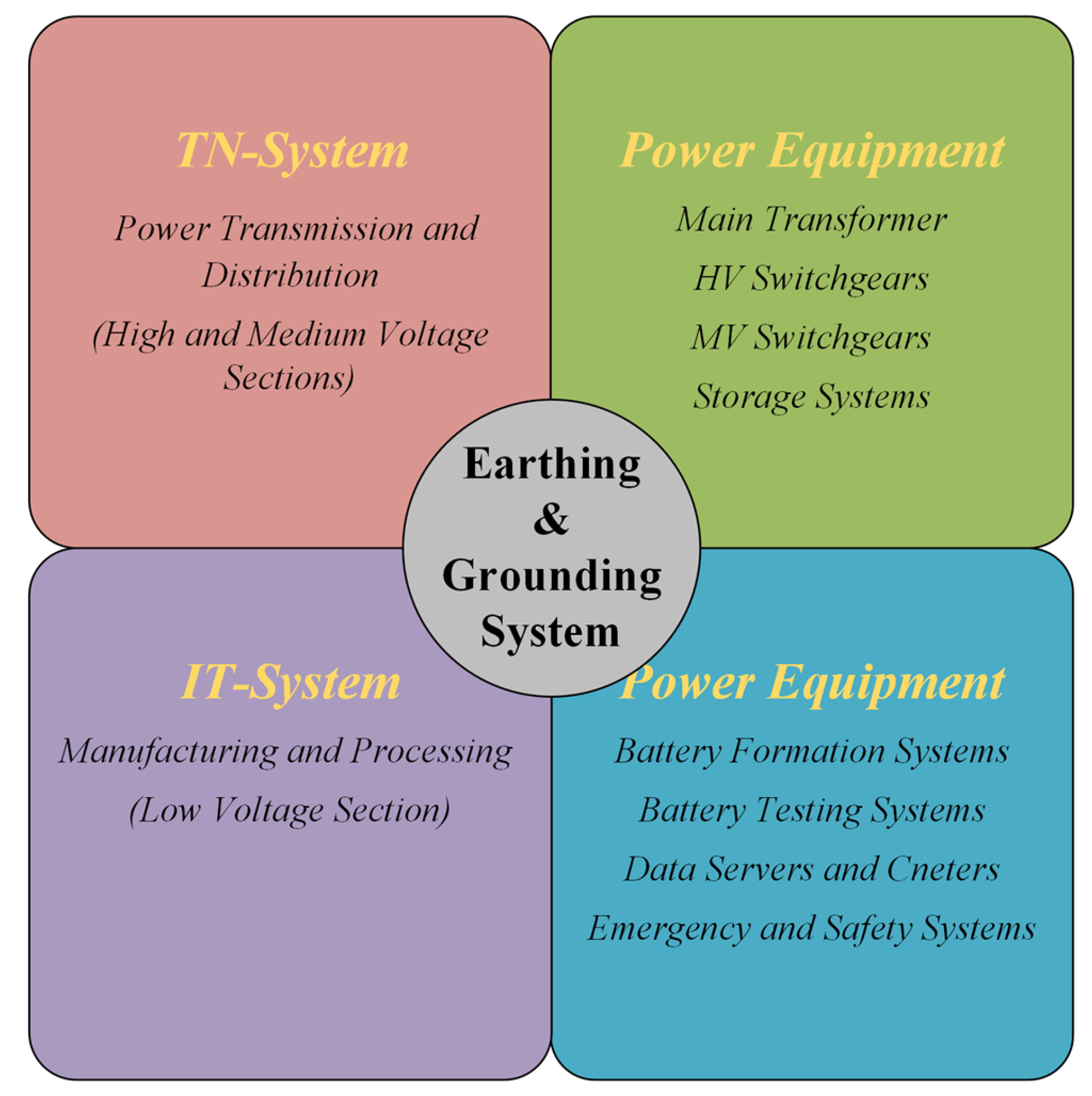
In the gigafactory, it is critical to choose a suitable earthing and grounding system in accordance with the power equipment, operational voltage ranges, and the critical nature of the process. In the important stages of battery manufacturing, including the cell formation process, a combination of TN and IT systems is used to achieve optimal results.
The PDN of the gigafactory can be divided into two stages, i.e., the transmission and distribution stage and the manufacturing and processing stage. In the first stage, which includes the HV and MV sections of the PDN, the TN system is used to achieve optimal results. In the second stage (LV section of the PDN), power supply interruptions are minimized by implementing an IT system for the earthing and grounding of power equipment. This stage consists of the manufacturing and distribution section of the gigafactory.
Figure 9 shows the types and implementation of earthing and grounding systems. It shows the sections of the gigafactory where each earthing and grounding system is implemented. It also indicates two categories of power components according to the earthing and grounding system implementation.

5. Power Equipment

Different types of power equipment are used in a gigafactory, which are critical for the efficient and reliable working of the factory [64]. For the power system concerned, the cell formation process is the most critical part of a gigafactory. This section discusses the types of power equipment used in the gigafactory for the cell formation process [65,66]. The key power equipment in the gigafactory is explained in the following sections of this article.
A.
Process-related power equipment
The power equipment specifically used in the cell formation process includes the following:
  • Cell formation chargers are the most critical devices in the formation process. These chargers are used to charge the battery cells for the very first time at the beginning of the formation process. This process usually takes several hours [67]. Battery performance and longevity are the main purposes of the cell formation process. These were achieved by using high-precision chargers, which are mandatory to ensure a uniform charging profile across all cells inside a formation chamber. Voltage and current profiles are adjusted according to the real-time monitoring of cells through advanced formation chargers with unique charging and discharging circuitries [68].
  • The devices used to perform continuous charging–discharging cycles for the cell formation process are called cyclers [69].
    These devices track cell performance and capacity during charging and discharging cycles. These are equipped with precise control and real-time monitoring. The cells are passed through rigorous cycles with high levels of power, voltage, and current, and must prove their quality by showing consistent performance throughout the formation cycles [23].
  • The battery management system (BMS) is installed with formation equipment to acquire real-time data accurately during the cell formation process. Real-time voltage, current, temperature, and other parameters for each cell are monitored by this BMS [70]. BMS is used to optimize the formation process to enhance performance and efficiency by using the data collected to identify any cells that do not meet quality standards [71]. Robust safety systems are mandatory in the cell formation process because of the potential risks of thermal runaway and cell failure. The instances of thermal runaway over the years are listed in [72]. These safety systems are activated during anomalies and consist of fire suppression systems, gas detection sensors, and automated shutdown mechanisms [73]. To achieve greater efficiency and reliability, it is vital to integrate these power equipment systems into a cohesive and automated setup.
  • Advanced EMSs, used in modern gigafactories to monitor and control power equipment, are used to ensure optimal performance and energy consumption [74].
  • Automation technologies, including robotics and machine learning algorithms, are used to enhance the quality control and productivity of the manufacturing process [18].
  • This automation process is also used for predictive maintenance to predict and prevent failures even before their occurrence, and the data retrieved from equipment is continuously analyzed, enhancing the component lifespan and reducing the maintenance costs [75].
B.
Auxiliary power equipment
A considerable amount of total energy in a gigafactory is consumed by auxiliary power equipment. This power consumption may range from anywhere between 6.33% and 8.89% of the total power consumption of the plant [76]. These components are crucial for controlling the speed and torque of machines used in various manufacturing processes, including electric motors and variable-frequency drives (VFDs). A considerable amount of energy is saved, and higher production efficiency is achieved in the manufacturing process by using these high-efficiency motors and VFDs [65].
The Uninterruptible Power Supply (UPS) is also a crucial piece of power equipment in a gigafactory. UPS ensures uninterrupted operation during power failures and protects crucial devices and data by providing backup power.
HVAC systems are also important power equipment inside the gigafactory. HVAC systems are used to create optimal environmental conditions by controlling temperature, air, and humidity within the manufacturing facility. Technologically advanced HVAC systems can improve power efficiency and decrease operational costs by using smart controls and heat recovery units [9].
Energy-efficient lighting systems are another necessary type of power-consuming equipment in a gigafactory. Electricity consumption can be significantly reduced by using LED lighting systems with smart controls.
Power consumption efficiency can be further improved by using automated lighting systems that can adjust the intensity of lighting based on occupancy and ambient light conditions [77].

6. Thermal Management

The thermal management of the heat generated during the manufacturing of LIBs in a gigafactory is a very critical aspect of its optimal operation. An effective thermal management system is mandatory to have an efficient, reliable, and safe manufacturing process [78]. This section explores the various techniques and technologies used in a gigafactory for thermal management. The thermal management system of a gigafactory covers several aspects, including waste heat recovery, the cooling of the manufacturing equipment and devices, and HVAC systems for the facility [79]. Key factors of the thermal management system are briefed in the following paragraphs.
A thermal management system is mandatory for the safety of the cells during the cell formation process. LIBs are highly sensitive to temperature fluctuations and can be severely affected if the temperature inside the formation chambers is not controlled and managed properly [80]. If cells get overheated during the formation process, it can result in thermal runaway, fires, or even explosions. So, thermal management and control are of the utmost importance, keeping the temperature within a suitable range to enable cells to prevent such incidents [81].
Apart from the safety of the cells, the performance and lifecycle of the LIBs are also influenced by the temperature of the manufacturing environment, specifically the formation chambers. It is mandatory to have consistent and suitable thermal conditions to achieve the optimal quality and efficiency of the batteries manufactured in the gigafactory [82].
In addition, a proper thermal management system also helps to enhance the overall energy efficiency of the factory as it optimizes the heating and cooling process of the facility, which results in a reduction in energy consumption [83,84].
Air handling units (AHUs) are another type of component used for thermal management in the gigafactory. The basic purpose of the AHUs is to circulate air throughout the factory. AHUs consist of heating and cooling coils, filters, and humidifiers to achieve the desirable air quality and temperature in the factory premises. They maintain a suitable working environment inside the gigafactory [85].
These AHUs are also used to cool down manufacturing equipment and processes. Chillers in the AHUs use coolant to remove heat. Then, the heat is dissipated by the cooling towers. AHUs are fundamental for maintaining low temperatures in critical areas of the factory, such as formation towers.
Ventilation is also an important component of a thermal management system. An efficient ventilation system is critical to maintain the desired air quality and remove excess heat from the factory. The air inside the gigafactory is polluted by several contaminants and chemicals released during the manufacturing process, and the ventilation system ensures the removal of these contaminants from various zones of the factory [86].
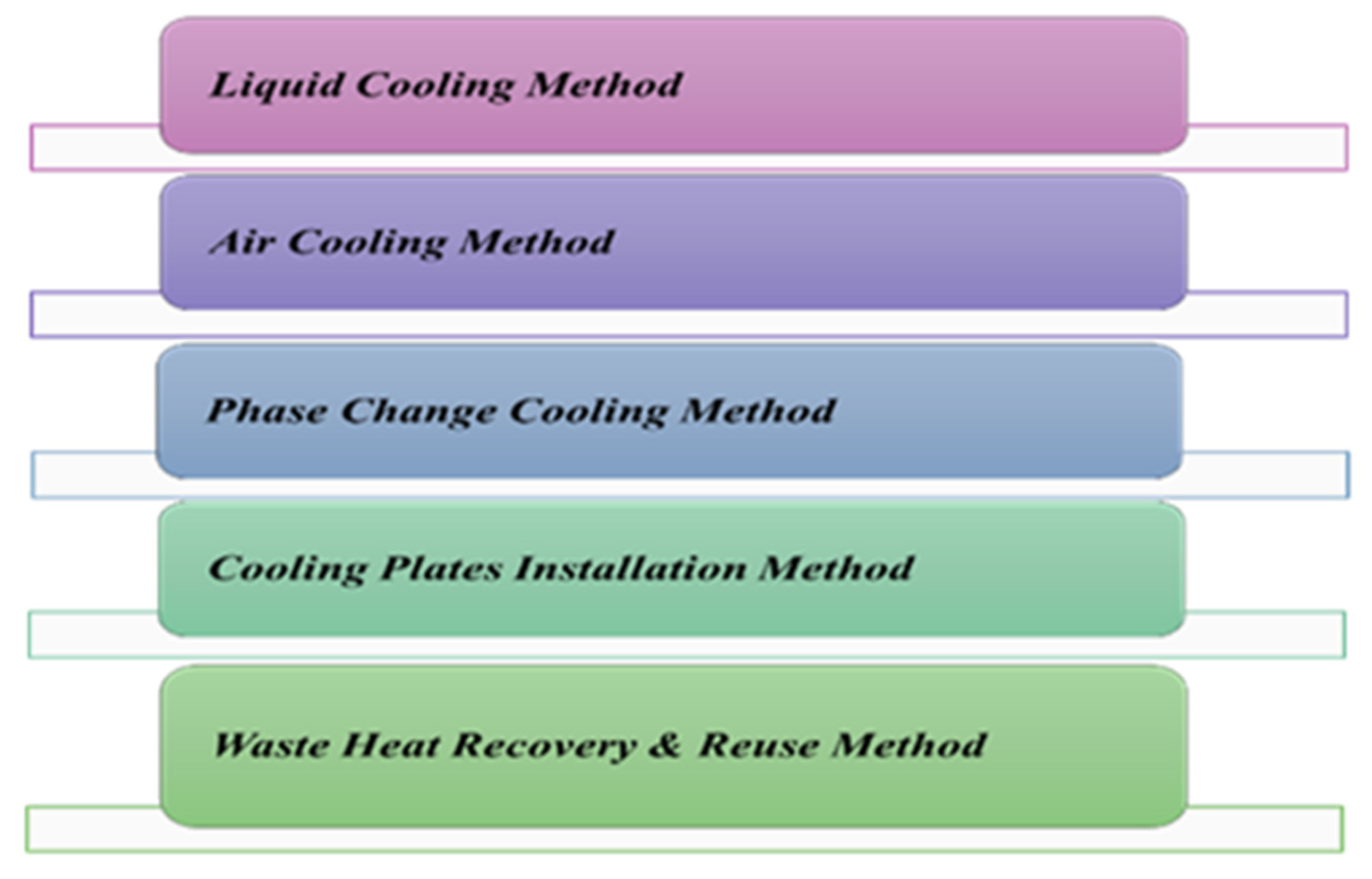
Temperature optimization is critical during production, specifically in the cell formation process. The presence of effective cooling methods is crucial for the cell formation process. These methods are summarized in Figure 10.
Among the most advanced cooling techniques used in existing gigafactories are liquid cooling systems. The liquid cooling system is highly efficient and effective in managing the large thermal loads generated by high-power equipment and manufacturing processes [87]. Coolant is continuously circulated through the cooling system’s heat exchangers around heat-intensive power equipment. Heat exchangers absorb and dissipate generated heat. The liquid cooling systems are considerably more efficient than the other cooling systems used in gigafactories [88].
The air-cooling system is another type of cooling technique commonly used in gigafactories. This system circulates air in the place of coolants to dissipate heat from heat-generating equipment and systems by using fans and blowers. Although this cooling method is less efficient than a liquid cooling system, it has a simpler working principle, and it is quite suitable for systems that generate relatively low thermal loads [89].
Phase Change Materials (PCMs) are also used in some places of the gigafactory for thermal management. PCMs act as effective thermal buffers. They absorb and release thermal energy while they transition from one phase to another. These materials are specifically used at places where it is crucial to have very precise temperature control, like formation chambers and dry rooms [90].
The cell formation process is a highly thermally intensive stage during the manufacturing of lithium-ion batteries. Considerable heat is generated due to the continuous charging and discharging of the lithium-ion cells [91].
It is fundamental to ensure that the temperature of the cell formation chambers is uniformly maintained to achieve optimal safety and performance. Advanced control and monitoring systems are installed along with these chambers to monitor and adjust temperature in real time during the formation process [92].
One of the most commonly used thermal management techniques during the formation process is the implementation of cooling plates. These plates directly dissipate heat generated from cells. Plates are integrated and installed in combination with the liquid cooling systems to achieve the desired thermal conditions in the formation chambers [93]. A combination of thermal imaging cameras and sensors is used to monitor the temperature distribution across the cells in the formation chambers. The presence of the hotspots is identified in the formation chambers that need cooling [94].
Another important technique for thermal management in a gigafactory is to use waste heat recovery systems. These systems can enhance the overall energy efficiency of the factory by capturing generated heat and reusing it in various industrial processes [95]. There are several ways to use waste heat recovery in a gigafactory, e.g., this recovered heat can be used to preheat materials or to heat some specific space by transferring it from exchangers, exhaust gases, or coolant.
The waste recovery heat can also be used as an additional source of electrical power for the factory by using Organic Rankine Cycle (ORC) systems to convert this low-grade waste heat into electrical power [96]. The power generated from these ORC systems can be used to run cooling processes and reduce the requirement for electrical energy in HVAC systems [97].

7. Regenerative Function

This section explores the details of the methodologies and techniques used for the implementation of the regenerative function in a gigafactory [98].
The LIB cell manufacturing process incurs significant energy losses. Capturing and reusing this wasted energy improves the overall energy efficiency of the manufacturing process [99]. In addition to reducing the price, the application of the regenerative function also minimizes the environmental impact of the gigafactory and makes it more sustainable and environmentally friendly [100].
One of the most common applications of regenerative function is the implementation of automated guided vehicle (AGV) conveyor systems, used for transportation and material handling in the gigafactory. Regenerative braking systems installed in such transportation systems help to generate electrical power by capturing the kinetic energy produced by the braking of AGVs and conveyor belts.
The regenerative braking system accumulates energy produced by the slowing down of AGVs or conveyors. Batteries and capacitors are used to store the generated electrical power so it can be used to run other components of the power system. The power requirements from external power sources are reduced as a result [101].
Another system that can be incorporated with regenerative functioning is the HVAC system inside the gigafactory. It is implemented through heat recovery ventilators (HRVs) installed in the HVAC system. This system reduces the energy requirement for heating or cooling of the facility, as these HRVs capture the heat from the outgoing exhaust air and transfer it to the incoming fresh air [102].
Energy Recovery Ventilators (ERVs) are another example of systems that can use regenerative functions to manage humidity levels inside the gigafactory, working on similar principles as the HRVs. These systems are installed at places where it is crucial to control humidity levels. Power consumption requirements are reduced by implementing this system [103].
The cell formation process for LIBs has considerable potential for energy regeneration, as it is the most energy-intensive process inside the gigafactory, requiring about 33% of the total power consumed during the manufacturing of lithium-ion cells [16]. Once the cells are fully charged and passed through the discharging cycles, there is a huge potential to recapture the energy during these discharging cycles, which can be used to charge other cells or even run other operations in the facility [104]. In modern gigafactories, advanced bidirectional power converters are used with both formation chambers and formation towers. These converters can operate in both directions and enable these devices to feed the captured discharging energy back into the grid or store it in the central energy storage system [105].
Furthermore, a large number of production machines in a gigafactory are involved in cell production, such as presses, motors, and robotics. There can be a substantial reduction in energy consumption if regenerative functions are incorporated during the design of these high-power electrical machines. Such electrical machines are equipped with special drives that convert kinetic energy into electrical power while decelerating. This power can be used to run other power equipment in the gigafactory, or it can be supplied back to the grid [106].
It is compulsory to install a centralized energy storage system to make the application of regenerative functions more effective and efficient. This central energy storage system consists of high-capacity batteries or supercapacitors to store the recovered energy coming from different processes and equipment [107]. These energy storage systems can act as an additional power source during peak demand hours or as an alternative power source during outages [108].

8. Failure Analysis

A.
Failure analysis procedure
Effective failure analysis is imperative for enhanced production quality and reduction in shutdown time, improving the reliability, safety, and efficiency of the overall manufacturing process in the gigafactory [109].
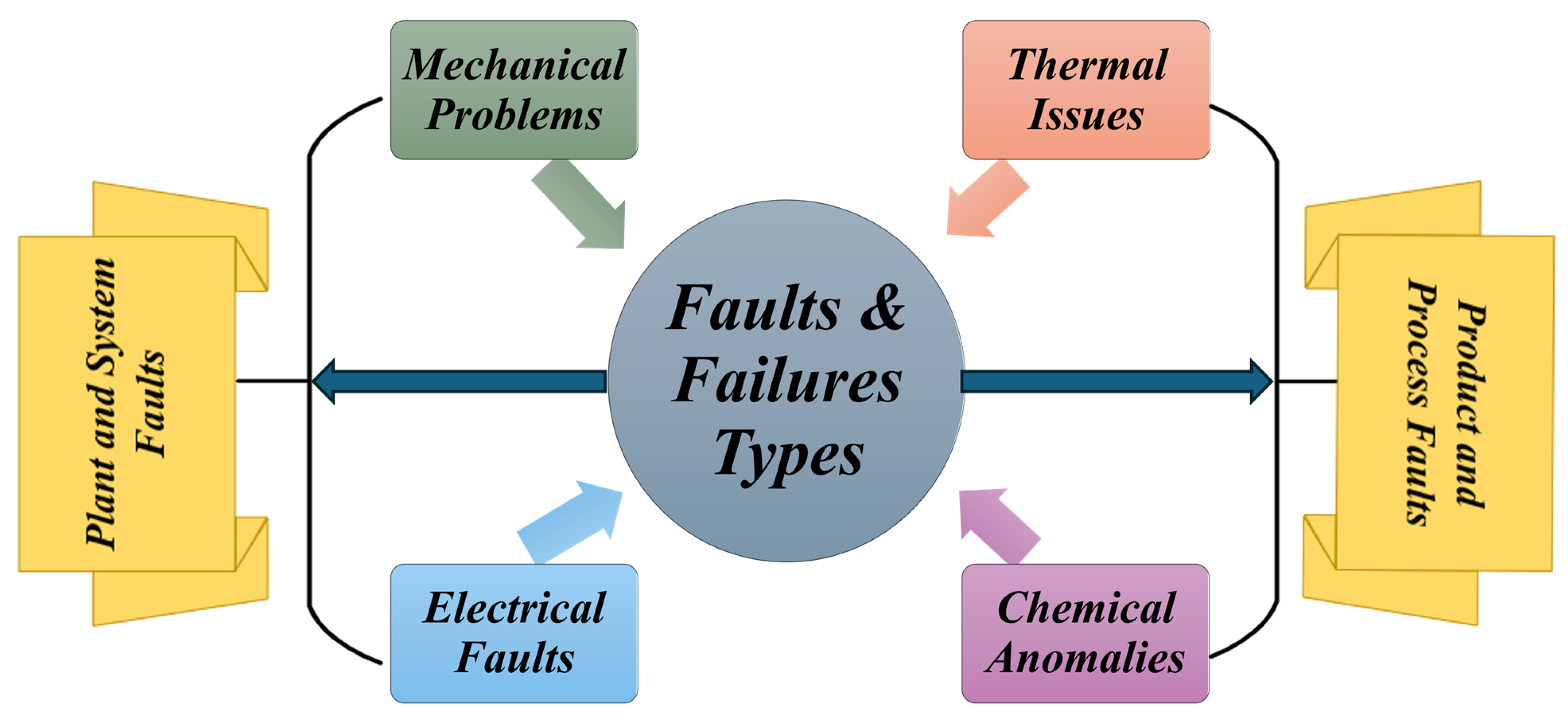
Failures can occur during several processes or at different stages. As explained in Figure 11, failures can occur at two levels: either at the plant and power system level or at the process and product level. Plant and system failures can be further divided into mechanical and electrical faults, which usually occur in the power and auxiliary equipment. Likewise, product and process faults can be further categorized into thermal and chemical issues. Product and process faults generally occur during the manufacturing and formation of LIBs.
Two of the most common types of plant and system failures are mechanical and electrical failures in the equipment used to operate the power system smoothly. These failures can occur in motors, drives, transformers, or components of the HVAC systems. These failures can prove fatal and can result in the disruption or complete shutdown of operations [110].
Another type of failure is a fault, which occurs during the manufacturing processes of LIB cells. This failure occurs during the formation process due to improper formation protocols, defective thermal management, or wrong material handling. Generally, these failures can be more costly because they go unnoticed and may result in defective production. These are usually called individual defects and do not usually result in a complete shutdown of the plant, but can be fixed by tweaking parameters or through the replacement of small electronic components [111].
Historical failure data is gathered from the gigafactory over a certain time period. For example, this data can be collected from sensors installed at critical locations, operational logs, maintenance records, and quality control reports. In modern gigafactories, real-time data collection can also be facilitated by advanced monitoring systems and Internet of Things (IoT) devices [112].
Failures can be identified and categorized into different failure modes, such as mechanical breakdowns, electrical faults, thermal issues, or chemical reactions [113].
Some of the prominent techniques used in failure analysis to inspect components without causing any harm to these parts are X-ray imaging, SCADA, ultrasonic testing, and infrared thermography [114].
In addition to the above-mentioned techniques, several additional methods can be adopted to analyze microstructural defects in materials. Such techniques involve Scanning Electron Microscopy (SEM) and Energy-Dispersive X-ray Spectroscopy (EDS) [115].
Various analysis models and techniques are used to identify the root causes of failures in the gigafactory: Failure Mode and Effects Analysis (FMEA), Fault Tree Analysis (FTA), and root cause analysis (RCA) are prominent examples [116,117].
B.
Root cause identification and Preventive measures
Identifying root causes is essential for implementing preventive measures that minimize failure recurrence and ensure uninterrupted gigafactory operations.
(1)
Root Cause Identification
The most important part of failure analysis is the root cause identification of failures to facilitate failure elimination. It can also prevent accidents and improve the safety of personnel and equipment inside the gigafactory [118]. Understanding these failure mechanisms also enhances the quality and quantity of production. Reduction in maintenance costs and the eradication of recurring problems can also be achieved by the effective management of these mechanisms. It can also improve production quality standards and lead to the complete elimination of failures during the manufacturing process [119].
The root causes of failures are eliminated by using root failure analysis: in the case of electrode degradation or separator failure, different techniques, such as electrochemical impedance spectroscopy (EIS) and differential scanning calorimetry (DSC), can be used. The problems identified using these techniques are addressed by implementing changes in the electrode manufacturing process, material sourcing, and cell assembly techniques [120].
The effectiveness of these suggested corrective actions can be validated by continuous monitoring and thorough testing to validate the analysis and prevent recurring failures [121].
(2)
Preventive Measures
Predictive analysis or protection can be assessed by the effects of these failures on the system’s reliability. This is achieved using different computational and simulation models. Weibull Analysis and Reliability Block Diagrams (RBDs) are examples of statistical methods that are used to analyze the failure data and reliability of the models [122].
After the suggested corrective measures have been implemented, extensive testing of the modified cells is conducted. The effectiveness and reliability of these measures in overall cell performance are checked under various test conditions.
Moreover, preventive measures are also implemented to avoid future failures. This preventive analysis is carried out using real-time monitoring and machine learning methods to collect data from critical equipment and prevent any failure from occurring during the manufacturing process [121,123].

9. Energy Consumption per Watt-Hour

The energy consumption per watt-hour is a critical parameter, and aims to estimate the exact amount of energy required to produce LIBs with a capacity of approximately one watt-hour. The required energy is estimated from the complete battery manufacturing process, starting from the processing of raw materials to the cell formation process of the cell assembly [4]. This section elaborates on the key factors that influence energy usage and the methods developed for measurements.
Energy consumption is important for a gigafactory, as it highlights the strategies for energy efficiency in the manufacturing process and key areas where energy can be saved. The energy used in the battery manufacturing process adds to production cost, and understanding energy consumption helps to reduce the operational costs of LIB cells. In addition to reducing the operational cost of the manufacturing process, this also decreases energy consumption, improves environmental sustainability, and minimizes the carbon footprint of the gigafactory [16].
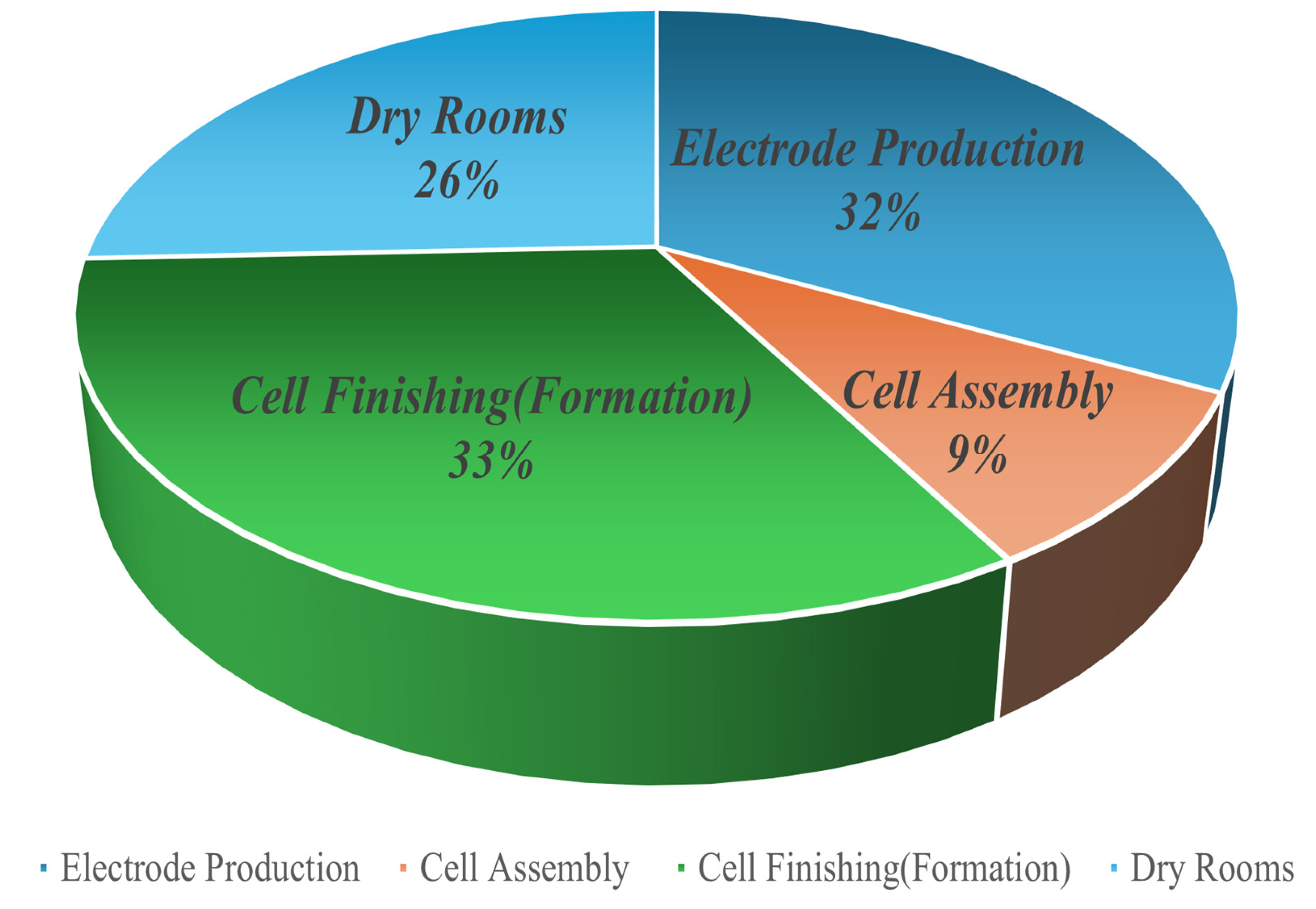
Figure 12 shows the percentages of power consumption during different stages of the cell manufacturing process. The most power is consumed during the cell finishing stage, which includes cell formation, aging, and the handling of the newly manufactured cells. It accounts for 33% of total power consumed, closely followed by the electrode production stage at 32%, the dry room at 26%, and cell assembly at 9%.
The total power consumed during the LIB cell manufacturing process for each kWh of capacity is 41.43 kWh. Table 1 shows the breakdown of power consumption at each important stage of the LIB manufacturing process, further divided into substages based on the activities performed at that particular stage of cell manufacturing.
In addition to the process, the energy consumption of different equipment, including mixers, coaters, and formation chambers, is also crucial for assessing energy consumption per watt-hour in the gigafactory [124].
Energy consumption can be further reduced by implementing advanced control and automation techniques to achieve an effective thermal management system for heating and cooling. Another way to improve efficiency in the LIB manufacturing process is to use high-quality raw materials [125].
Energy consumption per watt-hour is measured throughout the manufacturing process by monitoring and analyzing energy consumption. Energy consumption patterns and areas for improvement are analyzed by conducting comprehensive energy audits. These surveys are conducted by measuring the energy consumed during specific stages of the manufacturing process [4]. In advanced gigafactories, IoT sensors and smart meters are installed for the real-time monitoring of energy consumption. The data collected from the above-mentioned techniques provides a granular view of energy consumption. It helps in making well-informed decisions for energy consumption optimization.
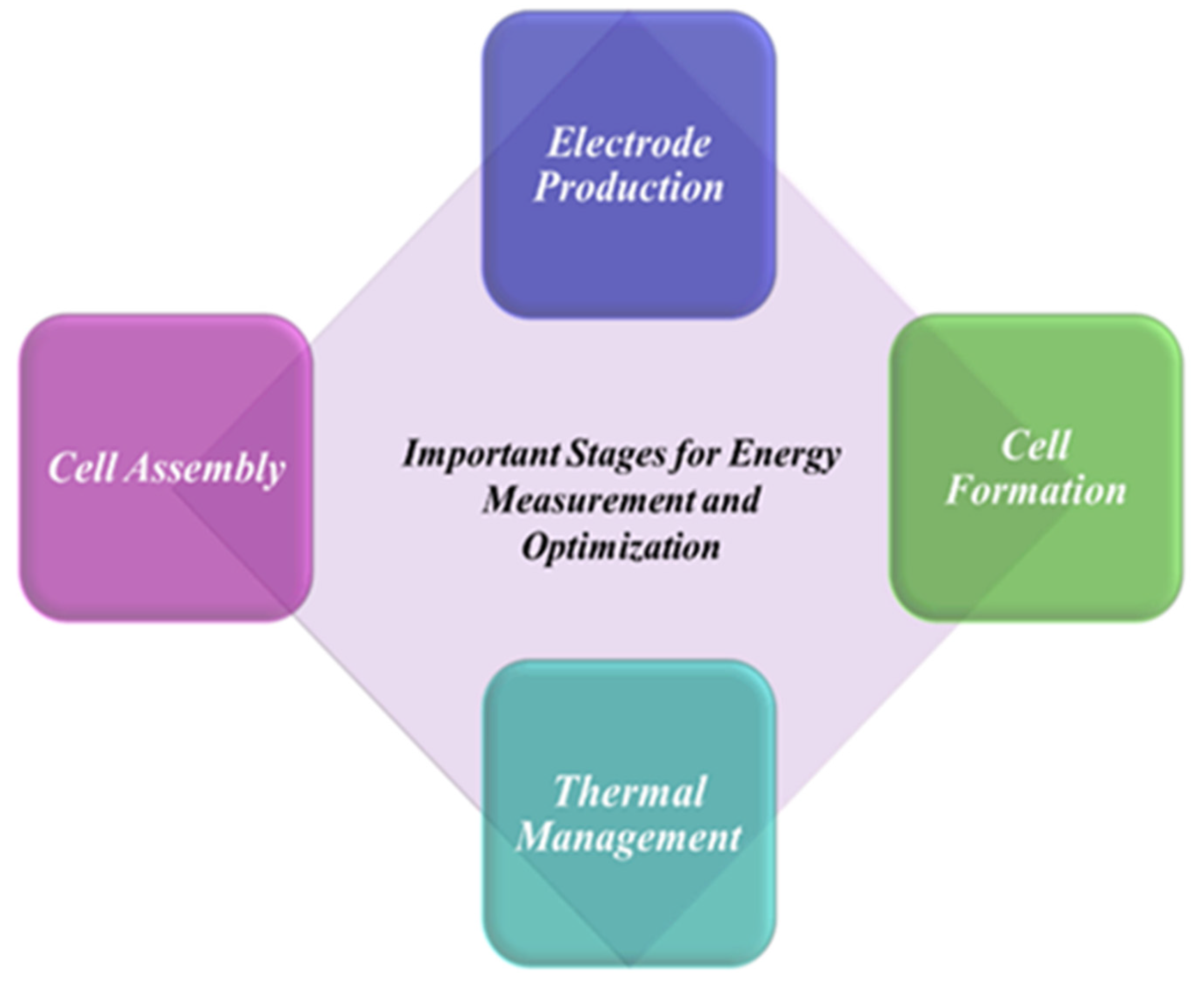
The total energy consumption is assessed throughout battery life by performing a lifecycle analysis from raw material extraction to battery disposal. Figure 13 shows some crucial stages at which this holistic approach is adopted to measure and optimize energy consumption [16]:
  • Electrode Production: The process of electrode production is quite energy-intensive and involves the mixing of active materials with binders. The energy used during this process can be reduced by optimizing mixer efficiency and decreasing batch sizes. Energy consumption can be further reduced by using advanced drying technologies. This process is quite energy-intensive because it involves coating electrodes onto the substrates.
  • Cell Assembly: Cell assembly requires significant amounts of energy at different stages, such as hermetic cell sealing, laser welding, and other joining processes, which require precise energy control to ensure high-quality products. Energy efficiency can be improved at the cell assembly stage by using advanced laser-cutting techniques, sealing technologies, and materials.
  • Cell Formation Process: The cell formation process is the most energy-intensive stage during the manufacturing process, as cells go through multiple and continuous charging and discharging cycles. The energy consumption during the cell formation process can be significantly reduced by using energy-efficient power systems and optimizing the formation protocols involving cycle duration, power supplied, chamber configuration, etc.
  • Thermal Management: The thermal management system of the gigafactory requires a considerable amount of energy as it is responsible for maintaining optimal temperatures in key production areas of the facility. Energy consumption during this process can be reduced by implementing ERVs and high-efficiency HVAC systems. Overall energy savings can be enhanced by installing efficient cooling systems for machinery and other process equipment. This reduces the requirement for external energy input to maintain optimal thermal conditions inside the factory.
Energy consumption can be further decreased by adopting various strategies.
  • Process Optimization: This can be achieved by implementing lean manufacturing principles to eliminate energy waste and improve process efficiency. Continuous improvements like Six Sigma [126] are implemented to identify and eliminate inefficiencies in the manufacturing process.
  • Advanced Technologies: Advanced automation systems are installed to optimize process control and decrease energy usage. The integration of smart manufacturing technologies, such as IoT and AI, helps in real-time monitoring and optimization of energy consumption.
  • Employee Training and Engagement: Energy efficiency awareness training programs must be conducted among employees to educate them about the importance of energy savings and to encourage them to contribute to the implementation of incentive training programs.

10. Discussions and Analysis

This section comprehensively discusses and analyzes the critical elements of power systems, based on the collective energy profile shape of a gigafactory.
Gigafactories generally require a significant amount of power for their operation and require a diverse mix of power sources. It is recommended to integrate renewable energy (such as solar and wind) with the grid power. This integration can help reduce load on the electricity grid and also make the factory sustainable. If the renewable resources produce excess power, it is suggested to use large-scale battery banks to create centralized energy storage systems. These centralized energy storage systems can be used as a supplementary or backup power source during power outages.
The paramount goal is a significant reduction in power losses and a steady power supply to all the equipment and processes in the facility. It is suggested that modern gigafactories should implement setups. These setups enable them to maintain a dynamic power flow and real-time monitoring. That helps in energy distribution optimization based on real-time demand and supply situations and reduces power losses. Overall energy efficiency can be enhanced by using data-driven insights, using information such as production schedules, equipment failures, or fluctuations in renewable energy generation, as well as by using low-loss transformers.
The energy consumption profile of the gigafactory can also be greatly affected by the selection and optimization of the power equipment. A large amount of specialized power equipment is extensively used in the cell formation process. All devices used in the cell formation process must be carefully designed and controlled to optimize the charging and discharging cycles for high-quality production. Moreover, predictive maintenance strategies are implemented to monitor equipment health and performance using sensors and data analytics so that optimal power flow and efficient operations are maintained, sudden unexpected failures can be prevented, and spikes are avoided.
It is recommended to use modern thermal management solutions in gigafactories, applying a combination of heat recovery, advanced cooling techniques, and efficient HVAC systems. Heat recovery systems capture heat and reuse it for various processes. The heat generated during the cell formation stage can be used to preheat the raw material or to maintain the temperature. This technique can result in energy savings and reduce operational costs.
Similar to the heat recovery system, it is recommended to use regenerative functions to maximize energy efficiency in the gigafactory, as the energy that would otherwise be wasted can be captured and reused. Regenerative systems should be further complemented by the installation of central energy storage systems to store recovered energy, to reduce energy costs, and to reduce dependence on external power sources.

11. Concluding Remarks

The power consumption analysis described in this paper provides a comprehensive analysis of the various factors that can affect the overall energy efficiency of a gigafactory.
The strategies suggested in this paper help to reduce operational costs and enable environmentally friendly production.
The largest amount of energy is consumed during the cell formation process of the LIB cell production; hence, the authors are developing innovative protocols for formation chambers to minimize energy losses at this stage of production by adopting innovative and energy-efficient techniques. Further research directions will focus on the development of more integrated and holistic approaches towards power consumption analysis in gigafactories to address critical issues like optimization in power consumption, reduction in operational costs, and the minimization of environmental effects by reducing CO2 emissions during production processes [18].
The optimal placement of AC/DC and DC/DC converters and the consequent choice of which segment of the internal distribution system could operate in either AC or DC will be an interesting research topic, even though it can be difficult to obtain detailed public information on the AC/DC and DC/DC energy consumption trade-off in the gigafactories. However, authors are currently working on an innovative formation system in which one AC/DC converter is used for the formation tower, and a minimal number of DC/DC converters are utilized for the formation chambers by implementing novel and innovative chamber configurations.

Funding

This research is co-funded by the European Union—Next Generation EU, Mission 4 Component 2-ECS00000036-CUP E14D23002000004 and MUR DM 117/Comau—Innovative formation system for lithium-ion cells project being carried out by a research collaboration between Politecnico di Torino and COMAU S.P.A. ITALY.

Data Availability Statement

No new data were created or analyzed in this study. Data sharing is not applicable to this article.

Conflicts of Interest

The authors declare no conflicts of interest. The funders had no role in the design of the study; in the collection, analyses, or interpretation of data; in the writing of the manuscript; or in the decision to publish the results.

References

  1. Bechberger, M.; Vorholt, F.; Bünting, A.; Oehl-Schalla, N.; Arnold-Triangeli, L.; Beermann, V.; Bilge, P.; Giacomini, M.; Steven, J.M.; Neupert, P.; et al. Sustainability of Battery Cell Production in Europe; VDI/VDE Innovation + Technik GmbH: Berlin, Germany, 2021. [Google Scholar]
  2. Yuan, C.; Deng, Y.; Li, T.; Yang, F. Manufacturing Energy Analysis of Lithium Ion Battery Pack for Electric Vehicles. CIRP Ann. Manuf. Technol. 2017, 66, 53–56. [Google Scholar] [CrossRef] [Scilit]
  3. Kallitsis, E. On the Energy Use of Battery Gigafactories. J. Clean. Prod. 2022, 364, 132573. [Google Scholar] [CrossRef] [Scilit]
  4. Davidsson Kurland, S. Energy Use for GWh-Scale Lithium-Ion Battery Production. Environ. Res. Commun. 2020, 2, 012001. [Google Scholar] [CrossRef] [Scilit]
  5. Zemite, L.; Kozadajevs, J.; Jansons, L.; Bode, I.; Dzelzitis, E.; Palkova, K. Integrating Renewable Energy Solutions in Small-Scale Industrial Facilities. Energies 2024, 17, 2792. [Google Scholar] [CrossRef] [Scilit]
  6. Tesla Impact Report; Austin, 2024. Available online: https://www.tesla.com/ns_videos/2023-tesla-impact-report-highlights.pdf (accessed on 25 January 2026).
  7. Choe, H.; Choi, Y.; Kim, J.H. Threshold Cell Diameter for High Thermal Insulation of Water-Blown Rigid Polyurethane Foams. J. Ind. Eng. Chem. 2019, 73, 344–350. [Google Scholar] [CrossRef] [Scilit]
  8. Liu, J.; Chen, H.; Huang, S.; Jiao, Y.; Chen, M. Recent Progress and Prospects in Liquid Cooling Thermal Management System for Lithium-Ion Batteries. Batteries 2023, 9, 400. [Google Scholar] [CrossRef] [Scilit]
  9. Olatunde, T.M.; Okwandu, A.C.; Akande, D.O.; Sikhakhane, Z.Q. Review of Energy-Efficient HVAC Technologies for Sustainable Buildings. Int. J. Sci. Technol. Res. Arch. 2024, 6, 12–20. [Google Scholar] [CrossRef] [Scilit]
  10. Jouhara, H.; Khordehgah, N.; Almahmoud, S.; Delpech, B.; Chauhan, A.; Tassou, S.A. Waste Heat Recovery Technologies and Applications. Therm. Sci. Eng. Prog. 2018, 6, 268–289. [Google Scholar] [CrossRef] [Scilit]
  11. Jouhara, H.; Olabi, A.G. Editorial: Industrial Waste Heat Recovery. Energy 2018, 160, 1–2. [Google Scholar] [CrossRef] [Scilit]
  12. Diez, L.; Marangé, P.; Levrat, É. Regeneration Management Tool for Industrial Ecosystem. IFAC-Pap. 2017, 50, 12950–12955. [Google Scholar] [CrossRef] [Scilit]
  13. Toren, M. Optimization of Transformer Parameters at Distribution and Power Levels with Hybrid Grey Wolf-Whale Optimization Algorithm. Eng. Sci. Technol. Int. J. 2023, 43, 101439. [Google Scholar] [CrossRef] [Scilit]
  14. Molęda, M.; Małysiak-Mrozek, B.; Ding, W.; Sunderam, V.; Mrozek, D. From Corrective to Predictive Maintenance—A Review of Maintenance Approaches for the Power Industry. Sensors 2023, 23, 5970. [Google Scholar] [CrossRef] [Scilit] [PubMed]
  15. Meriem, H.; Nora, H.; Samir, O. Predictive Maintenance for Smart Industrial Systems: A Roadmap. Procedia Comput. Sci. 2023, 220, 645–650. [Google Scholar] [CrossRef] [Scilit]
  16. Degen, F.; Schütte, M. Life Cycle Assessment of the Energy Consumption and GHG Emissions of State-of-the-Art Automotive Battery Cell Production. J. Clean. Prod. 2022, 330, 129798. [Google Scholar] [CrossRef] [Scilit]
  17. Gao, K.; Huang, Y.; Sadollah, A.; Wang, L. A Review of Energy-Efficient Scheduling in Intelligent Production Systems. Complex Intell. Syst. 2020, 6, 237–249. [Google Scholar] [CrossRef] [Scilit]
  18. Potter, K.; Blessing, E.; Oluwaseyi, J. Enhancing Industrial Automation Through the Integration of Deep Learning and Robotics. 2024. Available online: https://www.researchgate.net/publication/378522207_Enhancing_Industrial_Automation_through_the_Integration_of_Deep_Learning_and_Robotics_Authors (accessed on 25 January 2026).
  19. Xu, J. CEI and SEI Formation in Li-Ion Batteries. In Corrosion and Degradation in Fuel Cells, Supercapacitors and Batteries; Saji, V.S., Ed.; Springer Nature: Cham, Switzerland, 2024; pp. 307–324. ISBN 978-3-031-57012-4. [Google Scholar]
  20. Jinasena, A.; Burheim, O.S.; Strømman, A.H. A Flexible Model for Benchmarking the Energy Usage of Automotive Lithium-Ion Battery Cell Manufacturing. Batteries 2021, 7, 14. [Google Scholar] [CrossRef] [Scilit]
  21. Wood, D.L.; Li, J.; An, S.J. Formation Challenges of Lithium-Ion Battery Manufacturing. Joule 2019, 3, 2884–2888. [Google Scholar] [CrossRef] [Scilit]
  22. Tornheim, A.; Trask, S.E.; Zhang, Z. Evaluation of Electrolyte Oxidation Stability on Charged LiNi0.5Co0.2Mn0.3O2 athode Surface through Potentiostatic Holds. J. Electrochem. Soc. 2016, 163, A1717–A1722. [Google Scholar] [CrossRef] [Scilit]
  23. Schomburg, F.; Heidrich, B.; Wennemar, S.; Drees, R.; Roth, T.; Kurrat, M.; Heimes, H.; Jossen, A.; Winter, M.; Cheong, J.Y.; et al. Lithium-Ion Battery Cell Formation: Status and Future Directions towards a Knowledge-Based Process Design. Energy Environ. Sci. 2024, 17, 2686–2733. [Google Scholar] [CrossRef] [Scilit]
  24. Robben, T.; Offermanns, C.; Heimes, H.; Kampker, A. Advancements in Battery Cell Finalization: Insights from an Expert Survey and Prospects for Process Optimization. World Electr. Veh. J. 2024, 15, 219. [Google Scholar] [CrossRef] [Scilit]
  25. Weng, A.; Mohtat, P.; Attia, P.M.; Sulzer, V.; Lee, S.; Less, G.; Stefanopoulou, A. Predicting the Impact of Formation Protocols on Battery Lifetime Immediately after Manufacturing. Joule 2021, 5, 2971–2992. [Google Scholar] [CrossRef] [Scilit]
  26. Knehr, K.W.; Kubal, J.J.; Yoon, S.; Jeon, H.; Roh, W.J.; Ahmed, S. Energy Consumption of Lithium-Ion Pouch Cell Manufacturing Plants. J. Clean. Prod. 2024, 468, 143050. [Google Scholar] [CrossRef] [Scilit]
  27. Prakash, R.B.R.; Srinivasa Varma, P.; Ravikumar, C.; Vijay Muni, T.; Srinivasulu, A.; Bagadi, K.; Rajesh, A.; Sathish, K. Intelligent Energy Management for Distributed Power Plants and Battery Storage. Int. Trans. Electr. Energy Syst. 2023, 2023, 6490026. [Google Scholar] [CrossRef] [Scilit]
  28. Yasmin, R.; Amin, B.M.R.; Shah, R.; Barton, A. A Survey of Commercial and Industrial Demand Response Flexibility with Energy Storage Systems and Renewable Energy. Sustainability 2024, 16, 731. [Google Scholar] [CrossRef] [Scilit]
  29. Tesla Impact Report 2018; Nevada, 2019. Available online: https://www.tesla.com/ns_videos/tesla-impact-report-2019.pdf (accessed on 25 January 2026).
  30. Caetano, N.S.; Martins, F.F.; Oliveira, G.M. Life Cycle Assessment of Renewable Energy Technologies. In The Renewable Energy-Water-Environment Nexus; Elsevier: Amsterdam, The Netherlands, 2024; pp. 37–79. [Google Scholar]
  31. Department for Business, Energy & Industrial Strategy. Combined Heat and Power-Technologies; The National Archives: London, UK, 2021. [Google Scholar]
  32. Fraunhofer Research Institution for Battery Cell Production FFB. Time Production Output Mastering Ramp-up of Battery Production 2. Available online: https://www.ffb.fraunhofer.de/content/dam/ipt/forschungsfertigung-batteriezelle/Bilder/presse-medien/whitepaper-ramp-up/Whitepaper_Mastering%20Ramp-up%20of%20Battery%20Production.pdf (accessed on 25 January 2026).
  33. ESG IT. LG Energy Solution ESG REPORT; Seoul, 2024. Available online: https://www.lgensol.com/upload/file/sustainability/LG_Energy_Solution_2024_ESG_Report_EN.pdf (accessed on 25 January 2026).
  34. Kumar, A.; Schei, T.; Ahenkorah, A.; Caceres Rodriguez, R.; Devernay, J.-M.; Freitas, M.; Hall, D.; Liu, Z.; Killingtveit, Å. Hydropower. In IPCC Special Report on Renewable Energy Sources and Climate Change; Cristobal Diaz, M., Krug, T., Eds.; Cambridge University Press: Cambridge, UK, 2011; pp. 1–60. [Google Scholar]
  35. Rodríguez Martínez, J.H.; Alcaraz Calderón, A.; Ruiz Flores, L.I.; Valdez Vargas, R. Technical and Economic Analysis of Cogeneration Systems for Refinery Power Plant Applications. In Proceedings of the ASME 2010 Power Conference, Chicago, IL, USA, 13–15 July 2010; ASMEDC: Chicago, IL, USA, 2010; pp. 499–507. [Google Scholar]
  36. De Souza, R.; Casisi, M.; Micheli, D.; Reini, M. A Review of Small–Medium Combined Heat and Power (CHP) Technologies and Their Role within the 100% Renewable Energy Systems Scenario. Energies 2021, 14, 5338. [Google Scholar] [CrossRef] [Scilit]
  37. Giaccone, L.; Canova, A. Economical Comparison of CHP Systems for Industrial User with Large Steam Demand. Appl. Energy 2009, 86, 904–914. [Google Scholar] [CrossRef] [Scilit]
  38. Bagherian, M.A.; Mehranzamir, K.; Pour, A.B.; Rezania, S.; Taghavi, E.; Nabipour-Afrouzi, H.; Dalvi-Esfahani, M.; Alizadeh, S.M. Classification and Analysis of Optimization Techniques for Integrated Energy Systems Utilizing Renewable Energy Sources: A Review for Chp and Cchp Systems. Processes 2021, 9, 339. [Google Scholar] [CrossRef] [Scilit]
  39. Wu, M.; Su Lee Ming, E.; Zheng, Y.; Dong, B.; Fai Yeong, C.; Holderbaum, W. Green Automation: Empowering a Sustainable Future with Energy-Efficient Autonomous Mobile Robots in Manufacturing. 2024. Available online: https://neric.salford.ac.uk/wp-content/uploads/sites/216/2024/09/Green-Automation-Empowering-a-Sustainable-Future-with-Energy-Efficient-Autonomous-Mobile-Robots-in-Manufacturing.pdf (accessed on 25 January 2026).
  40. Tesla. Power Pack System. 2022. Available online: https://impulsoragdl.com/wp-content/uploads/2020/09/Ficha-Tecnica-Power-Pack.pdf (accessed on 25 January 2026).
  41. Yulong, P.; Cavagnino, A.; Vaschetto, S.; Feng, C.; Tenconi, A. Flywheel Energy Storage Systems for Power Systems Application. In Proceedings of the 2017 6th International Conference on Clean Electrical Power (ICCEP), Santa Margherita Ligure, Italy, 27–29 June 2017; IEEE: New York, NY, USA, 2017; pp. 492–501. [Google Scholar]
  42. Bamisile, O.; Zheng, Z.; Adun, H.; Cai, D.; Ting, N.; Huang, Q. Development and Prospect of Flywheel Energy Storage Technology: A Citespace-Based Visual Analysis. Energy Rep. 2023, 9, 494–505. [Google Scholar] [CrossRef] [Scilit]
  43. Liang, N.; Zhang, J.; Zheng, F.; Pan, Z. A Multi-Time Scale Source–Load Scheduling Method for Power Systems with Wind Power Considering Typical Industrial Production Processes. J. Electr. Eng. Technol. 2024, 19, 1033–1049. [Google Scholar] [CrossRef] [Scilit]
  44. Bouchard, P.; Voß, S.; Heilig, L.; Shi, X. A Case Study on Smart Grid Technologies with Renewable Energy for Central Parts of Hamburg. Sustainability 2023, 15, 15834. [Google Scholar] [CrossRef] [Scilit]
  45. Ali Syed, A.; Kumar Pundhir, S. Study of Different Distribution Models for Industrial Consumables and Applicability in India Limitations. EPRA Int. J. Multidiscip. Res. 2020, 6, 145–153. [Google Scholar] [CrossRef]
  46. Büschel, S. Industrial Plants Applications for Electric Power Distribution; Siegbert, H., Ed.; Siemens AG, Smart Infrastructure and Distribution Systems: Berlin, Germany, 2021; Volume 1. [Google Scholar]
  47. Amoiralis, E.I.; Tsili, M.A.; Kladas, A.G. Transformer Design and Optimization: A Literature Survey. IEEE Trans. Power Deliv. 2009, 24, 1999–2024. [Google Scholar] [CrossRef] [Scilit]
  48. Pinzón, S.; Yánez, S.; Ruiz, M. Optimal Location of Transformers in Electrical Distribution Networks Using Geographic Information Systems. Enfoque UTE 2020, 11, 84–95. [Google Scholar] [CrossRef] [Scilit]
  49. Amoiralis, E.I.; Tsili, M.A.; Kladas, A.G. Global Transformer Design Optimization Using Deterministic and Non-Deterministic Algorithms. In Proceedings of the 2012 XXth International Conference on Electrical Machines; IEEE: New York, NY, USA, 2012; pp. 2323–2331. [Google Scholar]
  50. Chakraborty, S. Components of Distribution System Distribution System. In Transmission & Distribution of Power; EE/JCGP; 2020; pp. 1–7. Available online: https://www.jcgpolytechnic.in/wp-content/uploads/2020/04/DEE-S4-Transmission-distribution-Components-of-Distribution-system.pdf (accessed on 25 January 2026).
  51. Fan, L.; Si, W.; Xuan, Y.; Sun, Z.; Zhao, J.; Xu, B.; Gu, Q. Multi-Objective Optimal Configuration of Multiple Switchgear Considering Distribution Network Fault Reconfiguration. IEEE Access 2021, 9, 69905–69912. [Google Scholar] [CrossRef] [Scilit]
  52. GCTT Industrial and Construction Cables Reference Guide; Highland Heights, 2016. Available online: https://na.prysmian.com/sites/na.prysmian.com/files/media/documents/INS-0177-0916%20Industrial%20Cable%20Product%20Reference%20Guide.pdf (accessed on 25 January 2026).
  53. Souran, D.M.; Safa, H.H.; Moghadam, B.G.; Ghasempour, M.; Heravi, P.T. Smart Grid Technology in Power Systems. In Advances in Intelligent Systems and Computing; Springer: Berlin/Heidelberg, Germany, 2016; Volume 357, pp. 1367–1381. [Google Scholar]
  54. Favuzza, S.; Ippolito, M.; Massaro, F.; Musca, R.; Riva Sanseverino, E.; Schillaci, G.; Zizzo, G. Building Automation and Control Systems and Electrical Distribution Grids: A Study on the Effects of Loads Control Logics on Power Losses and Peaks. Energies 2018, 11, 667. [Google Scholar] [CrossRef] [Scilit]
  55. Liu, Y. Research on Electrical Automation Devices under Embedded Real-Time Operating System Design. Appl. Math. Nonlinear Sci. 2024, 9, 1–19. [Google Scholar] [CrossRef] [Scilit]
  56. Alam, M.S.; Arefifar, S.A. Energy Management in Power Distribution Systems: Review, Classification, Limitations and Challenges. IEEE Access 2019, 7, 92979–93001. [Google Scholar] [CrossRef] [Scilit]
  57. Lakota, B.; Exnar, Z.; Matejcek, M.; Sostronek, M. Backup Power Supply System Analysis. Adv. Electr. Electron. Eng. 2015, 13, 115–119. [Google Scholar] [CrossRef] [Scilit]
  58. Faraji, J.; Babaei, M.; Bayati, N.; Ahejazi, M. A Comparative Study between Traditional Backup Generator Systems and Renewable Energy Based Microgrids for Power Resilience Enhancement of a Local Clinic. Electronics 2019, 8, 1485. [Google Scholar] [CrossRef] [Scilit]
  59. Das, C.K.; Bass, O.; Kothapalli, G.; Mahmoud, T.S.; Habibi, D. Overview of Energy Storage Systems in Distribution Networks: Placement, Sizing, Operation, and Power Quality. Renew. Sustain. Energy Rev. 2018, 91, 1205–1230. [Google Scholar] [CrossRef] [Scilit]
  60. Kumar, Y.V.P.; Bhimasingu, R. Key Aspects of Smart Grid Design for Distribution System Automation: Architecture and Responsibilities. Procedia Technol. 2015, 21, 352–359. [Google Scholar] [CrossRef] [Scilit]
  61. Gardner, J.; Alanis, J. A Comparison of International Wiring and Grounding Systems with North American Methods. In Proceedings of the 2008 55th IEEE Petroleum and Chemical Industry Technical Conference; IEEE: New York, NY, USA, 2008; pp. 1–7. [Google Scholar]
  62. Panethiere, M.A. Analysis of Grounding and Bonding for Power Distribution Systems in Commercial, Industrial, and Institutional Buildings; Capitol Technology University: Laurel, MD, USA, 2022. [Google Scholar]
  63. Lu, W.-H.; Yao, W.; Luo, J.; Cheng, Z.; Cheng, J.-Z.; Zhang, P.-H.; Li, S.-S.; Wang, S.-R. Comparative Study of the Earthing Systems for Micro-Grid. Dianli Xitong Baohu Yu Kongzhi/Power Syst. Prot. Control 2012, 40, 103–108. [Google Scholar]
  64. Sajjadi, M.; Seifi, H. A New Approach for Parameter Estimation of Power System Equipment Models. In Proceedings of the 2019 International Power System Conference (PSC); IEEE: Tehran, Iran, 2019; pp. 530–535. [Google Scholar]
  65. Ibekwe, K.I.; Fabuyide, A.; Hamdan, A.; Ilojianya, V.I.; Etukudoh, E.A. Energy Efficiency through Variable Frequency Drives: Industrial Applications in Canada, USA, and Africa. Int. J. Sci. Res. Arch. 2024, 11, 730–736. [Google Scholar] [CrossRef] [Scilit]
  66. Zhao, H.; Zhang, W.; Zheng, K.; Xu, W. A Novel High-Efficient Lithium-Ion Battery Serial Formation System Scheme Based on Partial Power Conversion. J. Energy Storage 2024, 97, 112350. [Google Scholar] [CrossRef] [Scilit]
  67. Patnaik, L.; Praneeth, A.V.J.S.; Williamson, S.S. A Closed-Loop Constant-Temperature Constant-Voltage Charging Technique to Reduce Charge Time of Lithium-Ion Batteries. IEEE Trans. Ind. Electron. 2019, 66, 1059–1067. [Google Scholar] [CrossRef] [Scilit]
  68. Matsuda, M.; Matsumoto, S. Modeling of Manufacturing Equipment for Conguring a Virtual Production Line to Simulate Electric Power-Consumption. Trans. Inst. Syst. Control Inf. Eng. 2017, 30, 97–103. [Google Scholar] [CrossRef] [Scilit]
  69. Anseán, D.; García Fernández, V.; Gonzalez, M.; Carlos Viera, J.; Anseán, D.; García, V.; González, M.; Viera, J.; Antón, J.; Blanco, C. Efficient Fast-Charging Strategies for Li-Ion Batteries. In Proceedings of the EVS28 International Electric Vehicle Symposium and Exhibition, Goyang, Republic of Korea, 3–6 May 2015; pp. 1–11. [Google Scholar]
  70. Challoob, A.F.; Bin Rahmat, N.A.; Ramachandaramurthy, V.K.A.; Humaidi, A.J. Energy and Battery Management Systems for Electrical Vehicles: A Comprehensive Review & Recommendations. Energy Explor. Exploit. 2024, 42, 341–372. [Google Scholar] [CrossRef] [Scilit]
  71. Schnell, J.; Reinhart, G. Quality Management for Battery Production: A Quality Gate Concept. Procedia CIRP 2016, 57, 568–573. [Google Scholar] [CrossRef] [Scilit]
  72. Huhn, E.; Braxtan, N.; Chen, S.E.; Bombik, A.; Zhao, T.; Ma, L.; Sherman, J.; Roghani, S. Lithium-Ion Battery Thermal Runaway Suppression Using Water Spray Cooling. Energies 2025, 18, 2709. [Google Scholar] [CrossRef] [Scilit]
  73. Kompass, K.; Königs, S.; Florian, E.; Euhus, F.; Fuchs, F.; Zimmermann, S.; Schöneburg, R.; Rainer, J.; Saúl, M.; Genís, M. Safety of Electro Mobility-White Paper of the Fisita Intelligent Safety Working Group. 2023. Available online: https://www.researchgate.net/publication/371991285_Safety_of_Electro_Mobility_-_White_Paper_of_the_FISITA_Intelligent_Safety_Working_Group (accessed on 25 January 2026).
  74. Bruneo, D.; Cucinotta, A.; Minnolo, A.L.; Puliafito, A.; Scarpa, M. Energy Management in Industrial Plants. Computers 2012, 1, 24–40. [Google Scholar] [CrossRef] [Scilit]
  75. Musthopa; Harsanto, B.; Yunani, A. Electric Power Distribution Maintenance Model for Industrial Customers: Total Productive Maintenance (TPM), Reliability-Centered Maintenance (RCM), and Four-Discipline Execution (4DX) Approach. Energy Rep. 2023, 10, 3186–3196. [Google Scholar] [CrossRef] [Scilit]
  76. Gellings, C.W. Back to Basics: Enhancing Efficiency in the Generation and Delivery of Electricity. In Energy Efficiency: Towards the End of Demand Growth; Elsevier: Amsterdam, The Netherlands, 2013; pp. 375–417. ISBN 978-0-12397-887-5. [Google Scholar]
  77. Rajesh, T.; Aravindhan, S.; Sowmiya, M.; Thenmozhi, S. Energy Efficient Lighting System in Industries. Int. J. Appl. Sci. Eng. Manag. 2021, 2, 214–226. [Google Scholar]
  78. Ortiz, Y.; Arévalo, P.; Peña, D.; Jurado, F. Recent Advances in Thermal Management Strategies for Lithium-Ion Batteries: A Comprehensive Review. Batteries 2024, 10, 83. [Google Scholar] [CrossRef] [Scilit]
  79. Ghalkhani, M.; Habibi, S. Review of the Li-Ion Battery, Thermal Management, and AI-Based Battery Management System for EV Application. Energies 2022, 16, 185. [Google Scholar] [CrossRef] [Scilit]
  80. Chang, C.-H.; Gorin, C.; Zhu, B.; Beaucarne, G.; Ji, G.; Yoshida, S. Lithium-Ion Battery Thermal Event and Protection: A Review. SAE Int. J. Electrified Veh. 2023, 13, 357–398. [Google Scholar] [CrossRef] [Scilit]
  81. Madani, S.; Hajihosseini, M.; Ziebert, C.; Nandhakumar, I. Battery Thermal Management System for Greater Lifetime and Safety: Mini-Review. In Proceedings of the Engineering for Rural Development; Latvia University of Life Sciences and Technologies: Jelgava, Latvia, 2024; Volume 23, pp. 1073–1089. [Google Scholar]
  82. Ma, S.; Jiang, M.; Tao, P.; Song, C.; Wu, J.; Wang, J.; Deng, T.; Shang, W. Temperature Effect and Thermal Impact in Lithium-Ion Batteries: A Review. Prog. Nat. Sci. Mater. Int. 2018, 28, 653–666. [Google Scholar] [CrossRef] [Scilit]
  83. Kapp, S.; Choi, J.-K.; Kissock, K. Toward Energy-Efficient Industrial Thermal Systems for Regional Manufacturing Facilities. Energy Rep. 2022, 8, 1377–1387. [Google Scholar] [CrossRef] [Scilit]
  84. Mawson, V.J.; Hughes, B.R. Thermal Modelling of Manufacturing Processes and HVAC Systems. Energy 2020, 204, 117984. [Google Scholar] [CrossRef] [Scilit]
  85. Lun, Y.H.V.; Tung, S.L.D. Air Handling Unit. In Green Energy and Technology; Springer Science and Business Media Deutschland GmbH: Berlin/Heidelberg, Germany, 2020; pp. 51–64. [Google Scholar]
  86. Chen, C.; Lai, D.; Chen, Q. Energy Analysis of Three Ventilation Systems for a Large Machining Plant. Energy Build. 2020, 224, 110272. [Google Scholar] [CrossRef] [Scilit]
  87. Boshkova, I.; Titlov, A.; Volgusheva, N.; Kolesnychenko, N.; Sagala, T. Designing a System of Liquid Cooling for Industrial Microwave Installations. East.-Eur. J. Enterp. Technol. 2019, 4, 65–70. [Google Scholar] [CrossRef] [Scilit]
  88. Cheli, L.; Carcasci, C. Modelling and Analysis of a Liquid-Cooled System for Thermal Management Application of an Electronic Equipment. E3S Web Conf. 2020, 197, 10008. [Google Scholar] [CrossRef] [Scilit]
  89. Memar, S.; Napoles, O.M.; Hofland, B.; Melling, G. Simulation of Parallel Layered Air Cooling Thermal Management System for Li-Ion Batteries. In Proceedings of the 31st European Safety and Reliability Conference, ESREL 2021; Research Publishing: Singapore, 2021; Volume 1, pp. 2525–2532. [Google Scholar]
  90. Bianco, V.; De Rosa, M.; Vafai, K. Phase-Change Materials for Thermal Management of Electronic Devices. Appl. Therm. Eng. 2022, 214, 118839. [Google Scholar] [CrossRef] [Scilit]
  91. Bhattacharjee, A.; Mohanty, R.K.; Ghosh, A. Design of an Optimized Thermal Management System for Li-Ion Batteries under Different Discharging Conditions. Energies 2020, 13, 5695. [Google Scholar] [CrossRef] [Scilit]
  92. Kumar, K.; Sarkar, J.; Mondal, S.S. Assessment of Newly-Designed Hybrid Nanofluid-Cooled Micro-Channeled Thermal Management System for Li-Ion Battery. J. Electrochem. Energy Convers. Storage 2024, 21, 011011. [Google Scholar] [CrossRef] [Scilit]
  93. Napa, N.; Agrawal, M.K.; Tamma, B. Design of Novel Thermal Management System for Li-Ion Battery Module Using Metal Matrix Based Passive Cooling Method. J. Energy Storage 2023, 73, 109119. [Google Scholar] [CrossRef] [Scilit]
  94. Sequino, L.; Capasso, C.; Costanza, G.; Tata, M.E. Experimental Investigation on Thermal Effects of a Metal Foam-Based Frame Application for Lithium-Ion Cells. In Proceedings of the SAE International Journal of Advances and Current Practices in Mobility; SAE International: Warrendale, PA, USA, 2023; Volume 6, pp. 2141–2150. [Google Scholar]
  95. Mohammadaliha, N.; Amani, M.; Bahrami, M. Thermal Performance of Heat and Water Recovery Systems: Role of Condensing Heat Exchanger Material. Clean. Eng. Technol. 2020, 1, 100024. [Google Scholar] [CrossRef] [Scilit]
  96. Slauch, I.M.; Deceglie, M.G.; Silverman, T.J.; Ferry, V.E. Optical Approaches for Passive Thermal Management in C-Si Photovoltaic Modules. Cell Rep. Phys. Sci. 2021, 2, 100430. [Google Scholar] [CrossRef] [Scilit]
  97. Kim, S.H.; Doh, Y.; Heo, T.-W.; Lee, I.W. Economic Analysis of a Redox Flow Batteries-Based Energy Storage System for Energy Savings in Factory Energy Management System. Batteries 2023, 9, 418. [Google Scholar] [CrossRef] [Scilit]
  98. Khartchenko, N.V.; Kharchenko, V.M. Advanced Energy Systems, 2nd ed.; CRC Press: Boca Raton, FL, USA, 2010. [Google Scholar]
  99. Sarode, R.P.; Vinchurkar, S.M. An Approach to Recovering Heat from the Compressed Air System Based on Waste Heat Recovery: A Review. Energy Sources Part A Recovery Util. Environ. Eff. 2023, 45, 9465–9484. [Google Scholar]
  100. Ferreira, F.J.T.E.; de Almeida, A.T. Overview on Energy Saving Opportunities in Electric Motor Driven Systems—Part 1: System Efficiency Improvement. In Proceedings of the 2016 IEEE/IAS 52nd Industrial and Commercial Power Systems Technical Conference (I&CPS); IEEE: New York, NY, USA, 2016; pp. 1–8. [Google Scholar]
  101. Ferreira, F.J.T.E.; de Almeida, A.T. Overview on Energy Saving Opportunities in Electric Motor Driven Systems—Part 2: Regeneration and Output Power Reduction. In Proceedings of the 2016 IEEE/IAS 52nd Industrial and Commercial Power Systems Technical Conference (I&CPS); IEEE: New York, NY, USA, 2016; pp. 1–8. [Google Scholar]
  102. Šebo, J.; Prester, J.; Šebová, M. The Role of Environmental Management Systems and Energy Management Systems in the Adoption of Energy Recuperation Technologies in Central European Manufacturing Companies. Sustainability 2023, 15, 16913. [Google Scholar] [CrossRef] [Scilit]
  103. Moro, A.; Kwakye-Boateng, P. Heat Recovery Analysis of a Fixed Plate Energy Recovery Ventilator. Sustain. Energy Res. 2024, 11, 29. [Google Scholar] [CrossRef] [Scilit]
  104. Orozco, L.; Liao, W. Power Efficient Battery Formation/Testing System with Energy Recycling. System 2015, 512, 768. [Google Scholar]
  105. Chen, Y.-C.; Chang, Y.-C.; Cheng, J.-F.; Yu, W.-C.; Lin, C.-L. Regenerative Braking-Driving Control System. In Proceedings of the 2018 13th IEEE Conference on Industrial Electronics and Applications (ICIEA); IEEE: New York, NY, USA, 2018; pp. 887–892. [Google Scholar]
  106. Badhoutiya, A.; Darokar, H.; Verma, R.P.; Saraswat, M.; Devaraj, S.; Raj, V.H.; Abdulhussain, Z.N. Regenerative Manufacturing: Crafting a Sustainable Future through Design and Production. E3S Web Conf. 2023, 453, 01038. [Google Scholar] [CrossRef] [Scilit]
  107. Potrč, S.; Nemet, A.; Čuček, L.; Varbanov, P.S.; Kravanja, Z. Synthesis of a Regenerative Energy System—Beyond Carbon Emissions Neutrality. Renew. Sustain. Energy Rev. 2022, 169, 112924. [Google Scholar] [CrossRef] [Scilit]
  108. Ferreira, F.J.T.E.; de Almeida, A.T. Reducing Energy Costs in Electric-Motor-Driven Systems: Savings Through Output Power Reduction and Energy Regeneration. IEEE Ind. Appl. Mag. 2018, 24, 84–97. [Google Scholar] [CrossRef] [Scilit]
  109. Durham, M.O.; Robert Durham, C.A.; Rosemary Durham, C.; Jason Coffin, C. Electrical Failure Analysis for Fire & Incident Investigations Lightning Excerpts; Durham, 2011. Available online: https://www.scribd.com/document/127712615/Electrical-Failure-Analysis-for-Fire-and-Incident-Investigation (accessed on 25 January 2026).
  110. Zitouni, A. Power Transformer Differential Relay Reliability Assessment Using False Trip Root Cause Analysis. In Proceedings of the 2020 International Conference on Electrical Engineering (ICEE), Istanbul, Turkey, 25-27 September 2020; IEEE: New York, NY, USA, 2020; pp. 1–5. [Google Scholar]
  111. Nikolaev, A.; Maklakov, A.; Bulanov, M.; Gilemov, I.; Denisevich, A.; Afanasev, M. Current Electromagnetic Compatibility Problems of High-Power Industrial Electric Drives with Active Front-End Rectifiers Connected to a 6–35 KV Power Grid: A Comprehensive Overview. Energies 2023, 16, 293. [Google Scholar] [CrossRef] [Scilit]
  112. Bauermann, L.P.; Mesquita, L.V.; Bischoff, C.; Drews, M.; Fitz, O.; Heuer, A.; Biro, D. Scanning Acoustic Microscopy as a Non-Destructive Imaging Tool to Localize Defects inside Battery Cells. J. Power Sources Adv. 2020, 6, 100035. [Google Scholar] [CrossRef] [Scilit]
  113. Kılıç, L. Assessing and Improving Recommendations for Local Power Quality Efficiency for Industrial Plants with the Help of Real Data. Int. J. Energy Smart Grid 2019, 4, 12–20. [Google Scholar] [CrossRef] [Scilit]
  114. Përvetica, R.; Përvetica, N.; Rexhepi, V.; Purellku, M. An Analysis of the Failures in the Power System Using the SCADA/EMS Database. In Proceedings of the 1st International Conference, CIGRE, Pristina, Kosovo, 6–11 January 2020; pp. 1–5. [Google Scholar]
  115. Girão, A.V.; Caputo, G.; Ferro, M.C. Application of Scanning Electron Microscopy–Energy Dispersive X-Ray Spectroscopy (SEM-EDS). Compr. Anal. Chem. 2017, 75, 153–168. [Google Scholar] [CrossRef] [Scilit]
  116. Cristea, G.; Constantinescu, D.M. A Comparative Critical Study between FMEA and FTA Risk Analysis Methods. IOP Conf. Ser. Mater. Sci. Eng. 2017, 252, 012046. [Google Scholar] [CrossRef] [Scilit]
  117. Pazhayattil, A.B.; Sharma, S. Root Cause Analysis (RCA) Methods. In Pharmaceutical Manufacturing Deviation and Failure Investigations: Principles, Practices, and Case Studies; Pazhayattil, A.B., Sharma, S., Eds.; Springer Nature: Cham, Switzerland, 2025; pp. 11–31. ISBN 978-3-031-86504-6. [Google Scholar]
  118. Rau, C.A.; Becker, D.G.; Besuner, P.M.; Cipolla, R.C.; Egan, G.R.; Gupta, P.; Johnson, D.P.; Tetelman, A.S.; Rettig, T.W.; Peters, D.C. Failure Analysis and Failure Prevention in Electric Power Systems. Nucl. Eng. Des. 1977, 43, 1–97. [Google Scholar] [CrossRef] [Scilit]
  119. Sun, K.; Hou, Y.; Sun, W.; Qi, J. Power System Control Under Cascading Failures Understanding, Mitigation, and System Restoration, 1st ed.; John Wiley & Sons: Hoboken, NJ, USA; IEEE: New York, NY, USA, 2019; ISBN 201-8-04229-7. [Google Scholar]
  120. Ariyoshi, K.; Siroma, Z.; Mineshige, A.; Takeno, M.; Fukutsuka, T.; Abe, T.; Uchida, S. Electrochemical Impedance Spectroscopy Part 1: Fundamentals. Electrochemistry 2022, 90, 102007. [Google Scholar] [CrossRef] [Scilit]
  121. Evans, D.; Luc, P.-M.; Tebruegge, C.; Kowal, J. Detection of Manufacturing Defects in Lithium-Ion Batteries-Analysis of the Potential of Computed Tomography Imaging. Energies 2023, 16, 6958. [Google Scholar] [CrossRef] [Scilit]
  122. Balasivanandha Prabu, S.; Karunamoorthy, L. Microstructure-Based Finite Element Analysis of Failure Prediction in Particle-Reinforced Metal–Matrix Composite. J. Mater. Process. Technol. 2008, 207, 53–62. [Google Scholar] [CrossRef] [Scilit]
  123. Hamed, M.; Soliman, A. Analyzing Failure to Prevent Problems. Ind. Manag. 2014, 5, 10–15. [Google Scholar] [CrossRef]
  124. Yang, Z.G. The Vanadium Redox-Flow Battery Is Big and Long-Lived, and It Won’t Catch Fire Is this the Ultimate Grid Battery. IEEE Spectr. 2017, 54, 36–41. [Google Scholar] [CrossRef] [Scilit]
  125. Hintsala, M. Industrial Management Production Requirements for 35 Gwh Lithium-Ion Battery Factory; University of VAASA, Faculty of Technology: Vaasa, Finland, 2018. [Google Scholar]
  126. Lee, J.; Yuvamitra, K.; Guiberteau, K.; Kozman, T.A. Six-Sigma Approach to Energy Management Planning. Strateg. Plan. Energy Environ. 2014, 33, 23–40. [Google Scholar] [CrossRef] [Scilit]
Figure 1. Key elements of the power system analysis.
Energies 19 01345 g001
Figure 2. Basic flowchart of the cell formation process.
Energies 19 01345 g002
Figure 3. Important stages of the cell formation process [23].
Energies 19 01345 g003
Figure 4. Power sources used in Tesla’s factory in Nevada.
Energies 19 01345 g004
Figure 5. Overview of the power distribution network of the gigafactory.
Energies 19 01345 g005
Figure 6. HV section of the power distribution network.
Energies 19 01345 g006
Figure 7. MV section of the power distribution network.
Energies 19 01345 g007
Figure 8. LV section of the power distribution network.
Energies 19 01345 g008
Figure 9. Earthing and grounding system.
Energies 19 01345 g009
Figure 10. Common cooling techniques used in gigafactories.
Energies 19 01345 g010
Figure 11. Failures and fault types in the gigafactory power system.
Energies 19 01345 g011
Figure 12. Percentage of energy consumed during different production stages of Li-ion cells [16].
Energies 19 01345 g012
Figure 13. Key stages for energy measurement and optimization.
Energies 19 01345 g013
Table 1. Power consumption at different process stages of the cell production of LIBs [16].
ProcessStagePower Consumed per kWh
Electrode ProductionMixing0.13
Coating and drying11.02
Calendaring0.53
Slitting0.16
Vacuum drying1.61
Subtotal 13.45
Cell AssemblyWinding0.25
Assembly1.59
Washing1.98
Subtotal 3.82
Cell FinishingFormation10.17
Aging and Testing1.39
Handling1.98
Subtotal 13.54
Dry RoomsDrying10.62
Subtotal 10.62
Grand Total 41.43
Disclaimer/Publisher’s Note: The statements, opinions and data contained in all publications are solely those of the individual author(s) and contributor(s) and not of MDPI and/or the editor(s). MDPI and/or the editor(s) disclaim responsibility for any injury to people or property resulting from any ideas, methods, instructions or products referred to in the content.