Article

Cascade Observer-Based Disturbance Estimation and Suppression for the Suspended Rotor in Maglev Hydrogen Recirculation Pump


by
Shiqiang Zheng
,
Jun Liu
and
Jinxiang Zhou
*
School of Instrumentation and Optoelectronic Engineering, Beihang University, Beijing 100191, China
*
Author to whom correspondence should be addressed.
Energies 2026, 19(4), 911; https://doi.org/10.3390/en19040911
Submission received: 6 January 2026 / Revised: 30 January 2026 / Accepted: 5 February 2026 / Published: 9 February 2026
(This article belongs to the Section A5: Hydrogen Energy)

Abstract

Magnetic bearing hydrogen recirculation pumps enable high-speed, wear-free operation but are sensitive to flow-induced disturbances. This study proposes a cascade-structured disturbance observer (CDOB) that fuses rotor displacement and bearing current signals to achieve robust disturbance estimation under model uncertainties, with low-pass filtering to ensure stability. The proposed method is validated through simulations and repeated experiments at multiple axial positions. Based on raw displacement signals, the CDOB reduces the average peak-to-peak axial displacement by approximately 35% compared with a traditional disturbance observer. Under axial offset conditions of −100 μm and +100 μm, the CDOB consistently achieves average displacement reductions of approximately 23% and 24%, respectively, demonstrating consistent disturbance suppression and robustness across repeated tests. These results indicate that the CDOB provides an effective and practical solution for disturbance suppression in magnetic bearing systems.

1. Introduction

As a key component of hydrogen fuel cell (HFC) systems, high-speed centrifugal hydrogen recirculation pumps are increasingly employed in fuel cell vehicles owing to their high efficiency and operational stability [1,2]. However, with the growing demand for compact system integration in vehicular applications, conventional centrifugal pumps supported by mechanical bearings face substantial challenges in meeting aerodynamic requirements characterized by low flow rates and high-pressure rise. These limitations underscore the urgent need to enhance the performance of high-energy-density impeller machinery [3]. In recent years, magnetic bearing technology has demonstrated remarkable advantages in precision applications such as onboard fly wheel energy storage systems and turbomachinery, benefiting from its frictionless operation, absence of lubrication, and extended service life [4,5]. Consequently, magnetic bearings present a promising and technically viable solution to the performance bottlenecks of traditional centrifugal hydrogen recirculation pumps, offering broad potential for future development and application.
However, in practical operation of hydrogen fuel cell (HFC) systems, complete separation between gaseous reactants (H2, O2 and H2O) and the generated liquid water within the flow channels is difficult to achieve [6]. This challenge becomes particularly pronounced under dynamic load conditions, where the delayed response of gas–liquid separation devices results in liquid water accumulation in the anode flow channels [7]. When dispersed liquid droplets within the two-phase flow impinge upon the impeller surface at high speed, the resulting transient impact forces can excite nonlinear vibrations in the magnetically suspended rotor system, thereby posing a serious threat to its dynamic stability. These time-varying external loads, introduced by two-phase flow disturbances, have emerged as a critical bottleneck limiting the engineering application of magnetically levitated hydrogen pumps. Consequently, the development of a robust magnetic bearing rotor controller is of great importance for advancing the adoption of magnetic suspension technology in HFC systems.
Evidently, the operational disturbances can essentially be regarded as uncertain external perturbations. Common approaches to address such issues include the extended state observer (ESO) [8] and the disturbance observer (DOB) methods [9]. The ESO estimates disturbances acting on the plant by augmenting them as additional system states, thereby providing strong disturbance rejection capability with low dependence on accurate system modeling. Owing to these advantages, it has been widely applied across various engineering fields [10,11]. Meanwhile, the DOB features a simpler structure and is easier to implement in practice. In ref. [12], a nonlinear disturbance observer was proposed that enables disturbance estimation using only output measurements. Ref. [13] introduced a control strategy that combines a PD controller with an adaptive DOB based on Lyapunov stability theory, effectively mitigating disturbances in active suspension systems under road excitation. Furthermore, ref. [14] presented a novel nonlinear friction observer for motion control, in which two asymptotically convergent friction estimators were derived without assuming a predefined friction model, offering new insights into motion control under complex dynamic conditions.
In the field of magnetic bearing control, DOB-based controllers have also been extensively investigated and applied. In ref. [15], multiple parallel full-order state observers were utilized for fault detection, state estimation, and disturbance observation. A game-theoretic detection filter was first employed to decouple external disturbances, followed by an H∞ model-matching method to assign the desired bandwidth to the decoupled disturbance observer. Experimental results verified the effectiveness of the proposed control scheme. Jin et al. [16] proposed a composite hierarchical disturbance rejection strategy, in which external disturbances were compensated using a disturbance observer, while internal system uncertainties were suppressed via an H∞ controller. Both simulation and experimental results demonstrated that the approaches exhibited superior external disturbance rejection performance compared with a standalone H∞ controller. In ref. [17], a robust nonlinear control strategy was developed for second-order nonlinear uncertain systems. Based on feedback linearization, the proposed method effectively eliminated system uncertainties and disturbances through appropriate filtering operations, as validated by simulation results. In the design of DOB-based magnetic bearing controllers, it is crucial to account for system uncertainties to ensure robustness, and model identification techniques have proven to be an effective means of achieving this goal [18]. With the continuous advancement of system identification methodologies, the accuracy of model estimation within specific frequency bands has been significantly enhanced [19]. In ref. [20], the active magnetic bearing (AMB) system was identified separately in both low- and high-frequency ranges, and distinct robust controllers were subsequently designed for each range. The performance of these controllers was evaluated under both static and dynamic operating conditions. Ref. [21] addressed system nonlinearities and parameter uncertainties by developing a multi-parameter identification model. Simulation and experimental results demonstrated that this method could accurately identify key parameters of the AMB system, including air gap length, rotor geometric center, static support load, and stiffness. In ref. [22], a generalized polynomial chaos expansion method was employed to identify AMB parameters and unbalanced forces. Based on the stochastic system response, the robustness and sensitivity of the system were experimentally assessed. Ref. [23] introduced a closed-loop identification approach for multi-input multi-output systems based on a decentralized decoupling control structure. The obtained parametric model was validated through comparison with experimental frequency-response data. Furthermore, ref. [24] developed a robust identification algorithm using frequency domain least-squares fitting to estimate multiple internal excitation parameters and system characteristics, providing a valuable framework for the identification of complex rotor systems. Despite the substantial progress achieved in DOB-based magnetic bearing control methods that incorporate system identification to address parameter uncertainties, several technical challenges remain. One of the key issues lies in the inherent trade-off between robustness and bandwidth in DOB-based designs. By appropriately configuring the observer’s filtering structure, the bandwidth range can be optimized to enhance the overall robustness of the control system. In this study, both current and displacement signals from the magnetic bearing control system are utilized while fully accounting for system uncertainties. Unlike existing AMB disturbance observers that rely on a single sensing channel, the proposed CDOB introduces a cascaded dual-channel structure that explicitly fuses displacement- and current-based disturbance information, improving robustness under parameter variations.
The remainder of this paper is organized as follows. Section 2 establishes the dynamic model of the magnetically levitated rotor subjected to load-induced disturbances. Section 3 provides a detailed analysis of system uncertainties and the corresponding model identification process. Based on these results, a magnetic bearing controller incorporating a CDOB is designed, and its stability is theoretically validated. Section 4 presents simulation and experimental studies to evaluate the effectiveness of the proposed control strategy in suppressing load disturbances in the magnetic bearing rotor system. Finally, Section 5 concludes the paper and summarizes the main findings.

2. Modeling

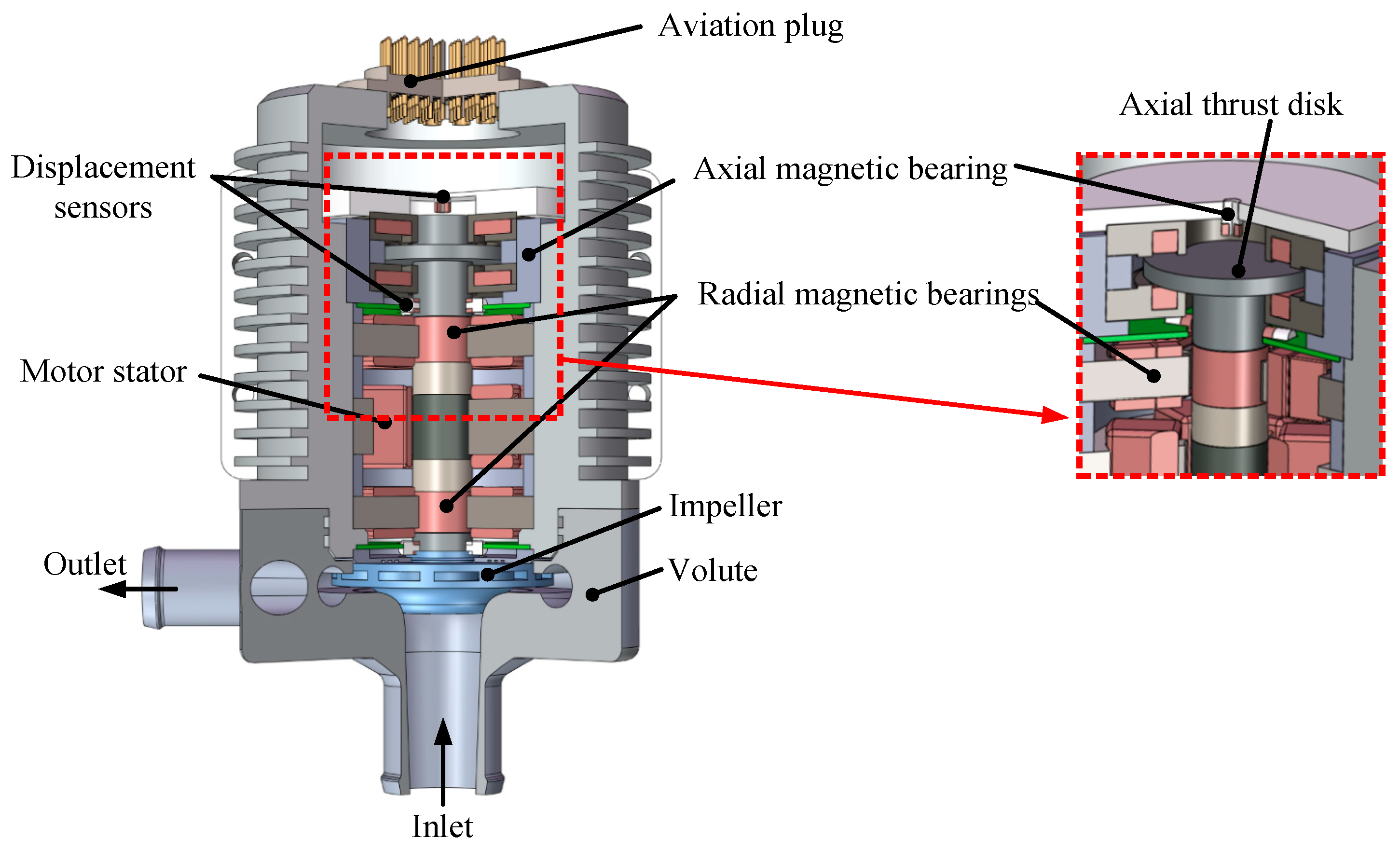
The assembly structure of the magnetically levitated hydrogen recirculation pump is shown in Figure 1. Two radial magnetic bearings and one axial magnetic bearing are employed to achieve stable suspension of the rotor with five degrees of freedom. The electromagnetic interaction between the motor stator and rotor drives the impeller to compress and recirculate hydrogen gas. Multiple sensors are integrated to monitor the rotor’s rotational speed and displacement in real time, providing essential feedback signals for the hydrogen pump’s control system. The rotor displacement is measured using eddy-current displacement sensors, which provide an analog voltage output ranging from 0.25 V to 2.75 V over an effective measurement range of 0.6 mm. As illustrated in Figure 1, the axial displacement sensor is mounted on the housing end cover and faces the axial thrust disk rigidly attached to the rotor shaft. Consequently, the measured displacement corresponds to the axial motion of the rotor relative to the stationary housing. Considering the spatial constraints imposed by other components within the fuel cell stack, the overall mechanical structure is dimensioned as 225 mm × 150 mm × 150 mm (length × width × height). Moreover, several nominal parameters of the hydrogen recirculation pump are listed in Table 1.

2.1. Fundamental Model of the Axial Magnetic Bearing

The axial dynamic model of the magnetic bearing–rotor system, as illustrated in Figure 1, can be formulated as follows [25]:
m z ¨ = K x z z + K i z i z
where m denotes the rotor mass, z represents the axial displacement of the rotor, Kxz and Kiz are the displacement stiffness and current stiffness coefficients of the axial magnetic bearing, respectively, and iz is the control current applied to the axial magnetic bearing.
By applying the Laplace transform to the axial dynamic equation described in Equation (1), the corresponding transfer function can be expressed as:
G d s = z s i z s = K i z m s 2 K x z
Meanwhile, in the control loop, the primary role of the power amplifier stage is to convert the controller output signal into the corresponding current supplied to the magnetic bearing coil. Accordingly, the power amplifier of the axial magnetic bearing can be equivalently represented by a first-order low-pass filter [26]:
G ω s = k ω z ω p z s + ω p z
where kωz and ωpz denote the gain coefficient and band width parameter of the axial power amplifier stage, respectively, and can be expressed as:
k ω z = k a m p z R z + k a m p z k i s ω p z = R z + k a m p z k i s L z
In Equation (4), Rz and Lz represent the resistance and inductance of the axial magnetic bearing coil, respectively; kampz is the forward amplification gain of the power amplifier stage, and kis denotes the current feedback gain. Furthermore, an incomplete differential PID controller is typically employed to stabilize the suspended rotor system, and can be expressed as:
G c s = k p k i k f + k d s 2 + k p k f + k i s + k p k i k f s 2 + k i s
The above theoretical model forms the foundation for axial disturbance rejection.

2.2. Basic Principle of the DOB

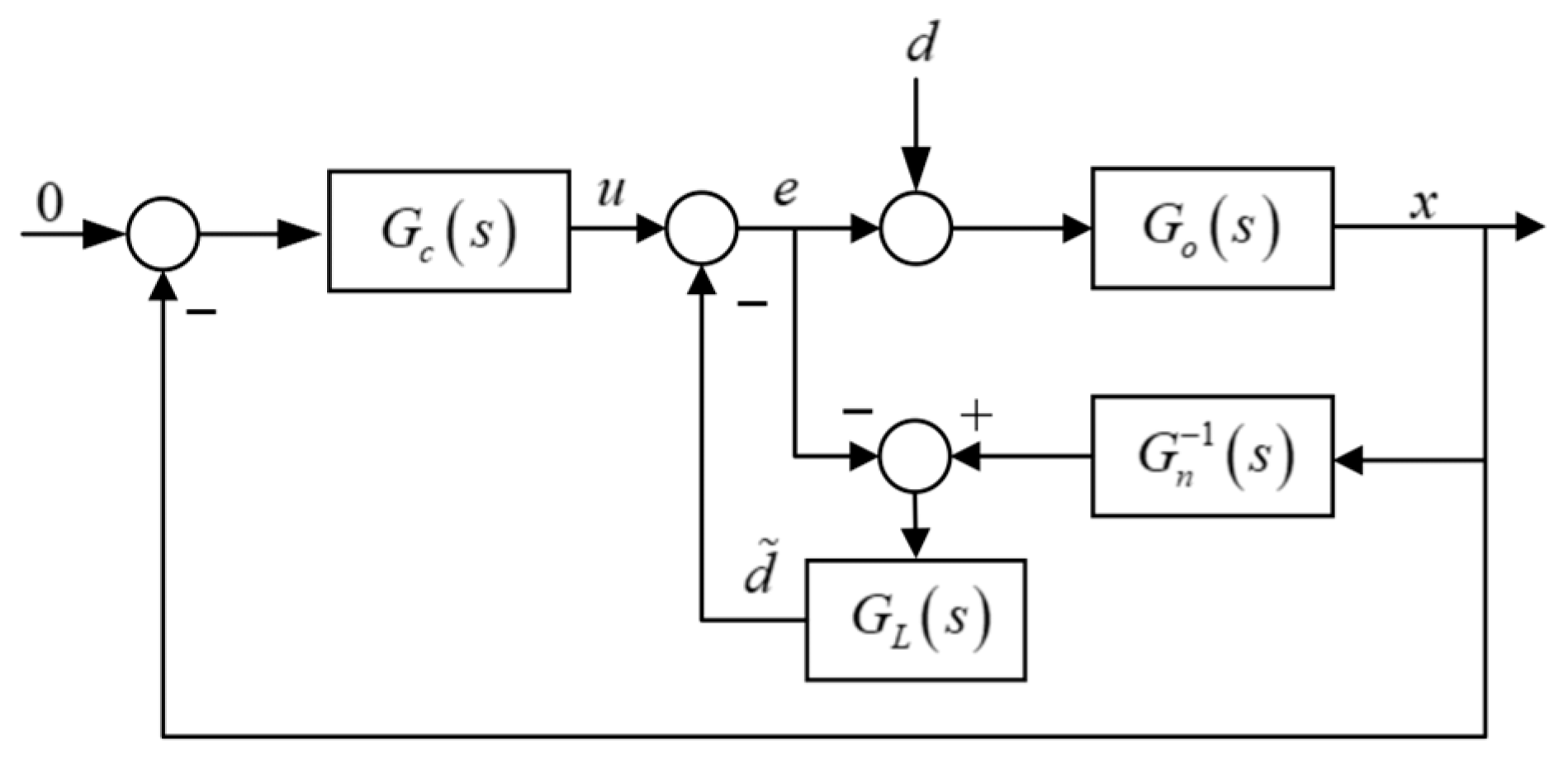
The disturbance observer (DOB) is a commonly used control method for handling unknown external disturbances. Its fundamental principle is illustrated in Figure 2, where u denotes the controller output, d represents the external disturbance acting on the system, and d ~ is the estimation of d. Due to parameter uncertainties in the actual plant model Gn(s), precise modeling is challenging, and its inverse model G o 1 ( s ) is physically unrealizable. Therefore, the nominal model Gn(s) is typically used as a substitute for Go(s). Meanwhile, a low-pass filter GL(s) is incorporated into the disturbance observer to realize the inverse of the nominal model G n 1 ( s ) . The use of the low-pass filter also effectively attenuates the influence of high-frequency noise on disturbance estimation. Accordingly, the expression for the disturbance estimate can be formulated as:
d ˜ = G o s G n 1 s G L s d + G o s G n 1 s 1 G L s e
When the disturbance frequency is below the cutoff frequency of the low-pass filter GL(s), such that ‖GL(s)‖ ≈ 1 and Gn(s) ≈ Go(s), then d ~ d . Therefore, the cutoff frequency of the low-pass filter directly affects the disturbance observer’s tracking performance for low-frequency disturbances.

2.3. Disturbance Estimation Principle of CDOB

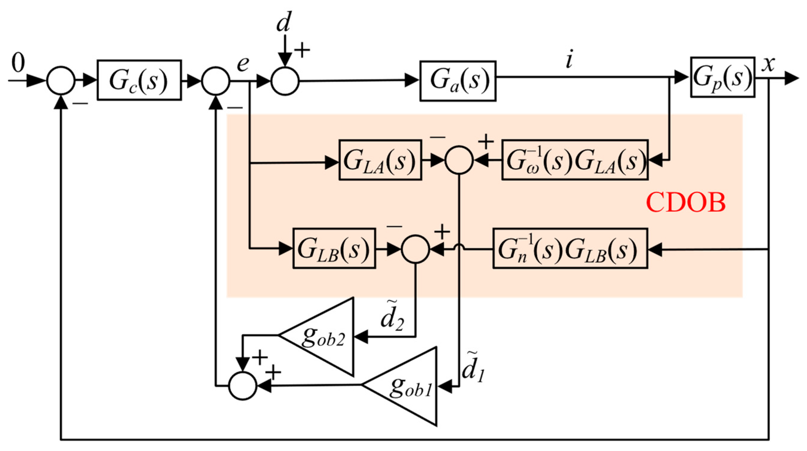
To enhance the accuracy of disturbance estimation, this study proposes a CDOB method, whose fundamental structure is illustrated in Figure 3. The internal signals involved are defined as follows:
(1)
x(t): axial displacement of the rotor measured by the eddy-current sensor.
(2)
i(t): axial bearing control current.
(3)
u(t): control input applied to the axial magnetic bearing.
(4)
d(t): lumped disturbance acting on the magnetic bearing-rotor system.
(5)
d ^ 1 ( t ) : disturbance estimate obtained from the current-based observer channel.
(6)
d ^ 2 ( t ) : disturbance estimate obtained from the displacement-based observer channel.
(7)
d ^ ( t ) : fused disturbance estimate generated by a weighted combination of d ^ 1 ( t ) and d ^ 2 ( t ) .
(8)
GLA(s), GLB(s): low-pass filters applied in the displacement and current observer channels, respectively.
(9)
gob: weighting factor determining the contribution of the two disturbance estimation channels.
Figure 3. Block diagram of the CDOB.
Energies 19 00911 g003
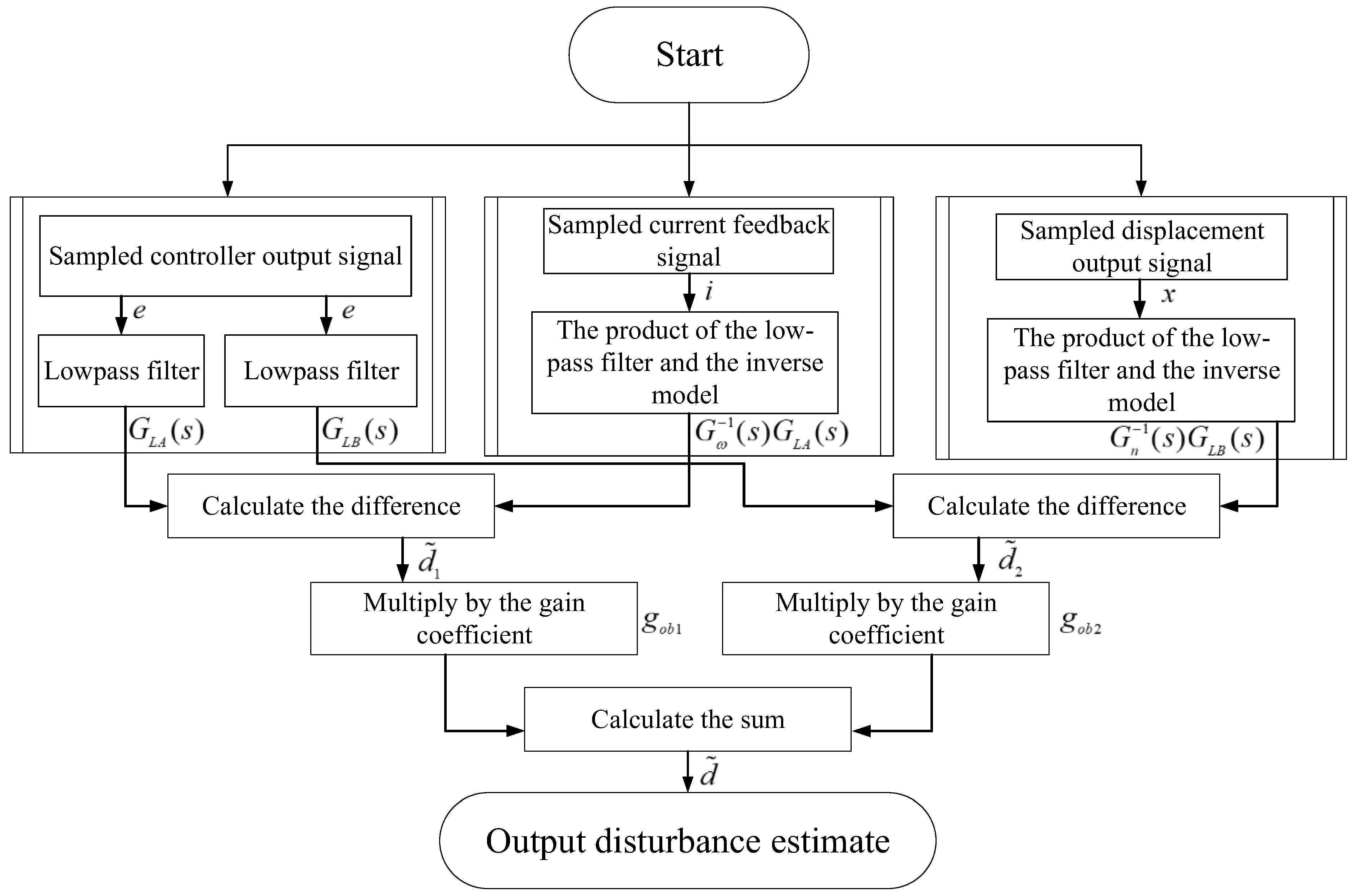
Moreover, Figure 4 presents a modular block-diagram representation of the proposed method. The implementation of the CDOB follows a structured procedure, which is summarized as follows:
(1)
The axial displacement signal and bearing current signal are sampled synchronously at the control sampling rate.
(2)
Based on frequency-response identification, a nominal axial plant model is constructed and used for observer design.
(3)
Two parallel disturbance estimation channels are implemented: a displacement-based channel and a current-based channel, each equipped with a low-pass filter to suppress high-frequency noise.
(4)
The disturbance estimates from the two channels are combined through a weighted fusion mechanism, where the weighting factor gob balances estimation accuracy and noise sensitivity.
(5)
The fused disturbance estimate is injected into the control loop for real-time disturbance compensation.
According to Figure 3, Gc(s) denotes the digital controller, Ga(s) represents the actual model of the system’s power amplifier stage, Gω(s) is the nominal model of the amplifier, and G ω 1 ( s ) denotes its inverse model. Gp(s) is the actual model of the magnetic bearing–rotor system, such that the overall plant model can be expressed as Go(s) = Ga(s)∙Gp(s). Then, d ~ 1 and d ~ 2 can be formulated as:
d ˜ 1 = G a s G ω 1 s G L A s d + G a s G ω 1 s 1 G L A s e d ˜ 2 = G o s G n 1 s G L B s d + G o s G n 1 s 1 G L B s e .
Accordingly, the estimated disturbance d ~ can be expressed as:
d ˜ = g o b 1 d ˜ 1 + g o b 2 d ˜ 2
As previously discussed, when the disturbance frequency is lower than the cutoff frequency of the low-pass filters, both ‖GLA(s)‖ and ‖GLB(s)‖ can be approximated as 1. Under this condition, it can both provide accurate estimates of the disturbance d. The filters GLA(s) and GLB(s) should be designed individually based on the results of system identification. Meanwhile, the estimation gains can also be tuned separately according to the degree of model uncertainty. Without loss of generality, the estimation gain coefficients are defined as 1 > gob1 = gob > 0, and gob2 = 1 − gob.

3. CDOB Implementation

3.1. Analysis of Uncertainty in System Parameters

Kxz and Kiz are two critical parameters in the axial dynamic model of the magnetically levitated rotor. Their nominal values are typically obtained based on a local linear approximation when the rotor is centered within the stator of the magnetic bearing. However, due to eddy current losses inherent in magnetic bearing systems, both displacement stiffness and current stiffness tend to decrease proportionally [27]. Therefore, it is essential to account for the uncertainty in Kxz and Kiz arising from variations in the rotor’s axial position.
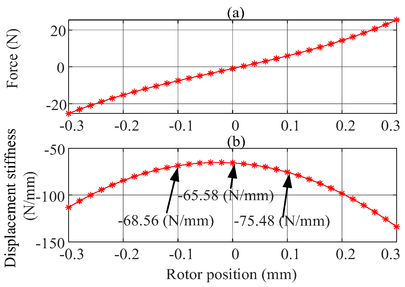
Finite element simulations were employed to characterize the relationships among magnetic bearing force, displacement stiffness, and rotor position, as illustrated in Figure 4. In practical engineering applications, protective bearings are typically used to constrain the rotor within a defined clearance to ensure stable suspension. For the axial magnetic bearing discussed in this study, the protection clearance range is from −0.3 mm to 0.3 mm. Given the system’s vibration tolerance requirement—that the peak-to-peak displacement of the rotor must not exceed 30% of the protective clearance—this work focuses on analyzing the variation characteristics of displacement and current stiffness within the range of −0.1 mm to 0.1 mm.
As shown in Figure 5a, the relationship between magnetic force and rotor position is approximately linear within this range. Figure 5b further indicates that when the rotor deviates ± 0.1 mm from its nominal central position, the displacement stiffness varies from its nominal value of −65.58 N/mm to −75.48 N/mm and −68.56 N/mm, respectively. This corresponds to a maximum relative variation of approximately 15.1%.
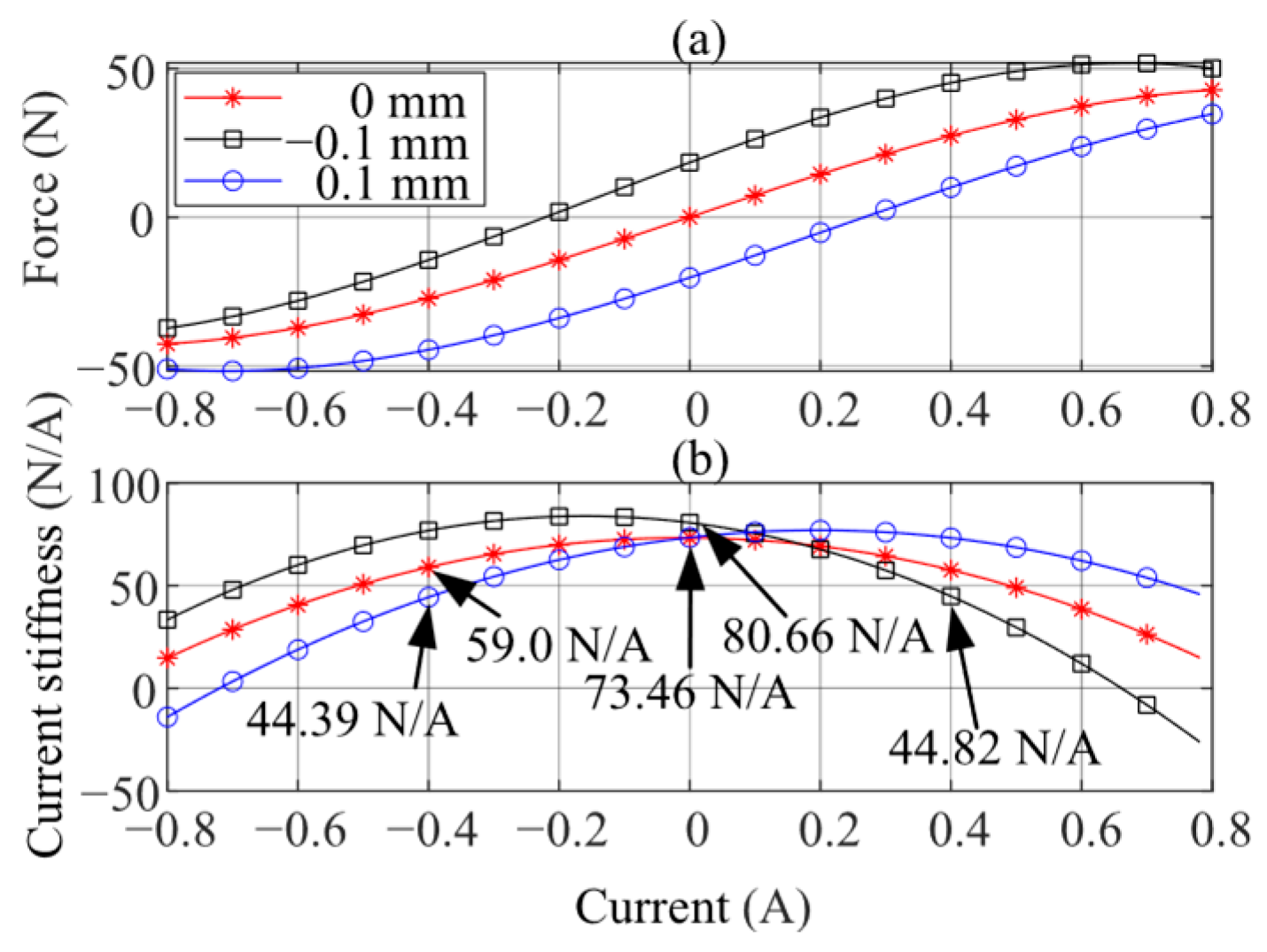
Similarly, the relationships among bearing force, current stiffness, and control current under various rotor positions and operating current conditions are obtained, as shown in Figure 6. According to Figure 6a, the relationship between bearing force and current is approximately linear in the vicinity of 0 A; however, as the current increases, a saturation effect becomes evident. A common approach involves applying saturation limits to the control input to constrain the control current within an approximately linear operating range. In this study, particular attention is given to the range of –0.4 A to 0.4 A. Based on the data in Figure 6a, the current stiffness at different rotor positions is computed and presented in Figure 6b. It can be observed that at the equilibrium position (0 mm), the current stiffness varies from 73.46 N/A to 59.00 N/A; at −0.1 mm, it ranges from 80.66 N/A to 44.82 N/A; and at 0.1 mm, it ranges from 73.46 N/A to 43.39 N/A. It can thus be concluded that the maximum uncertainty in current stiffness reaches up to 57.12%.
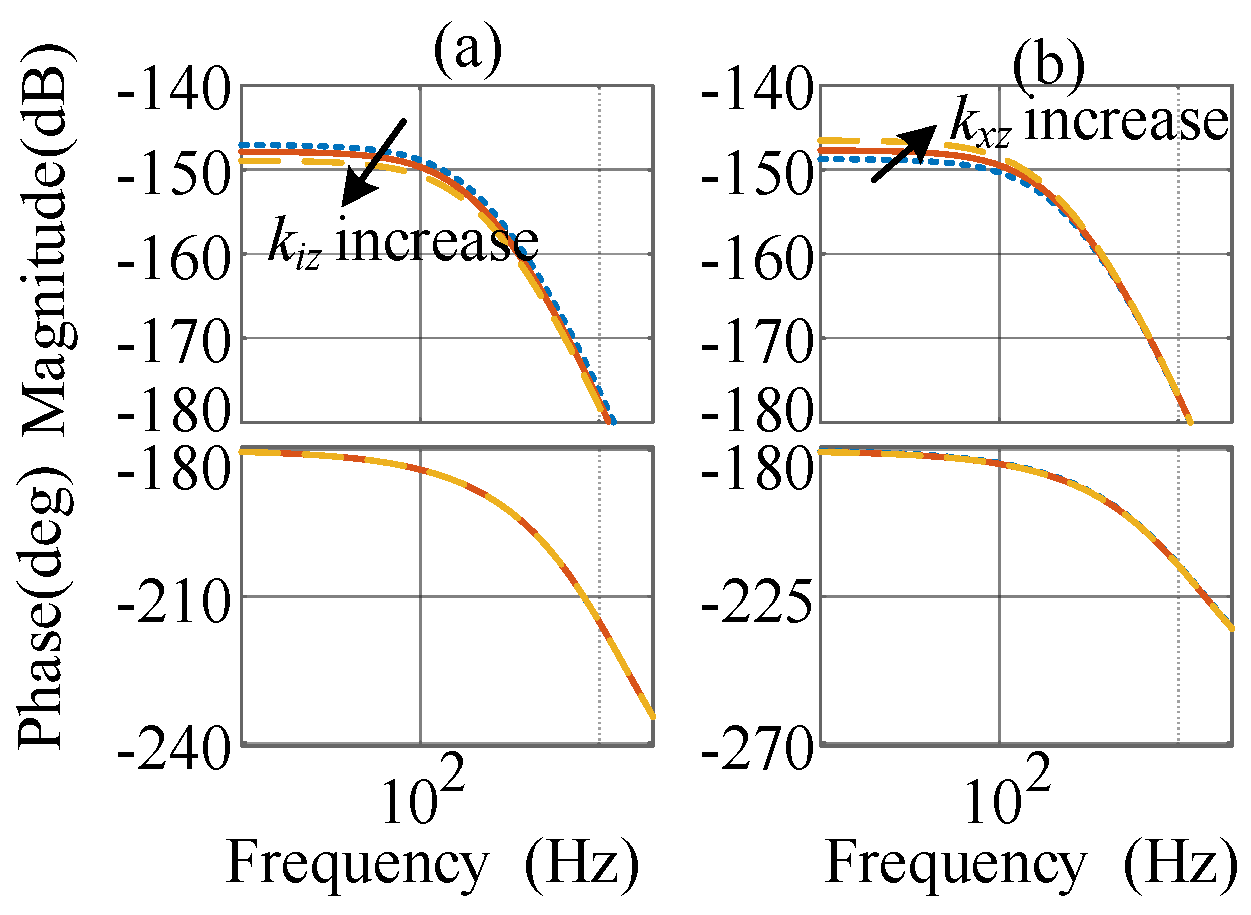
Based on the above analysis, the Bode plots of the rotor system are generated to illustrate the effects of variations in both displacement stiffness and current stiffness, as shown in Figure 7. The results indicate that such variations have a negligible influence on the system phase response, while the gain variation at low frequencies exhibits a consistent trend.
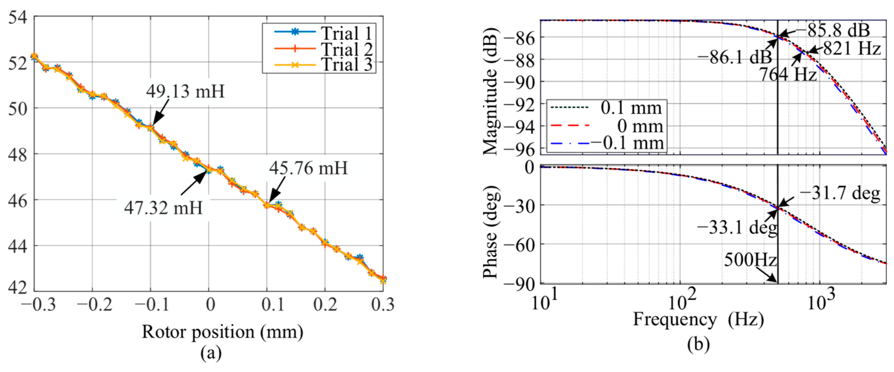
Furthermore, the parameter uncertainty of the power amplifier stage is analyzed. Rotor position variations change the inductance of the magnetic bearing coils, while resistance remains largely unaffected. As indicated in Equation (4), such variations can alter the amplifier bandwidth, introducing model uncertainty. Figure 8a illustrates the inductance variation at different rotor positions. As the rotor moves from −0.1 mm to 0.1 mm, the average of three inductance measurements shifts from 49.13 mH to 45.76 mH. Relative to the central position (47.32 mH), the maximum inductance uncertainty is approximately 3.83%.
Based on these measurements, the corresponding Bode plot of the power amplifier’s transfer function is shown in Figure 8b. It can be observed that the inductance variation leads to a reduction in amplifier bandwidth from 821 Hz to 764 Hz. Within the 500 Hz range, the gain variation of the amplifier is approximately 0.3 dB, with a phase shift of 1.4°. Within the 300 Hz range, both gain and phase remain nearly unchanged.

3.2. Model Identification

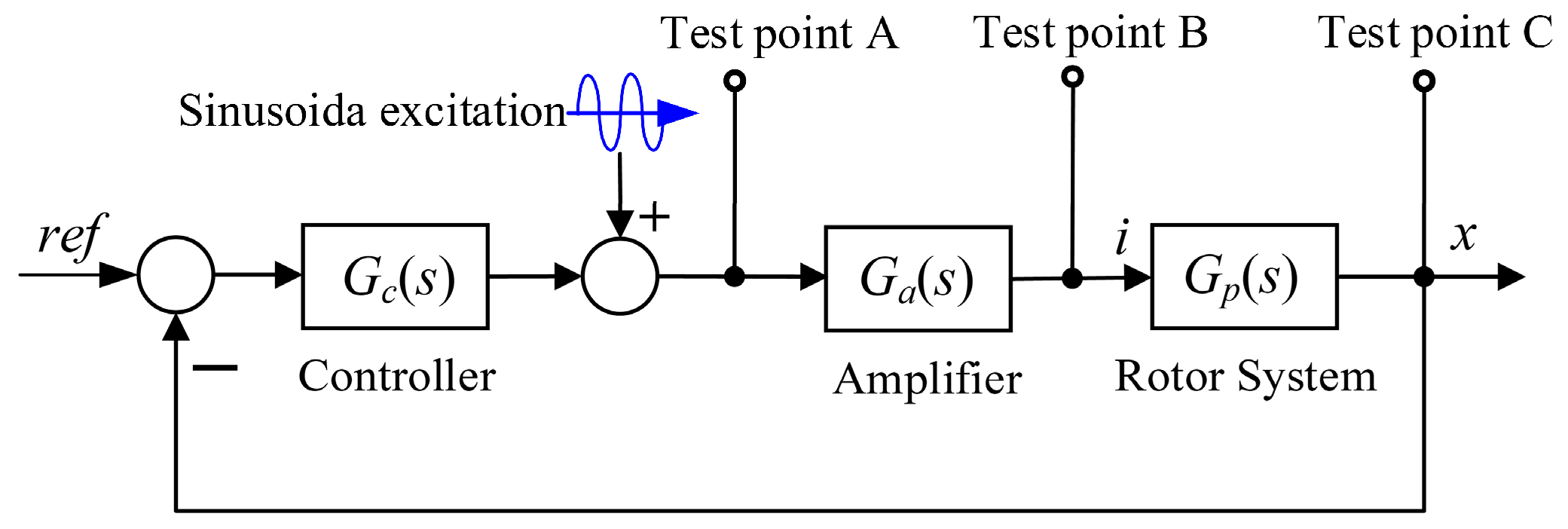
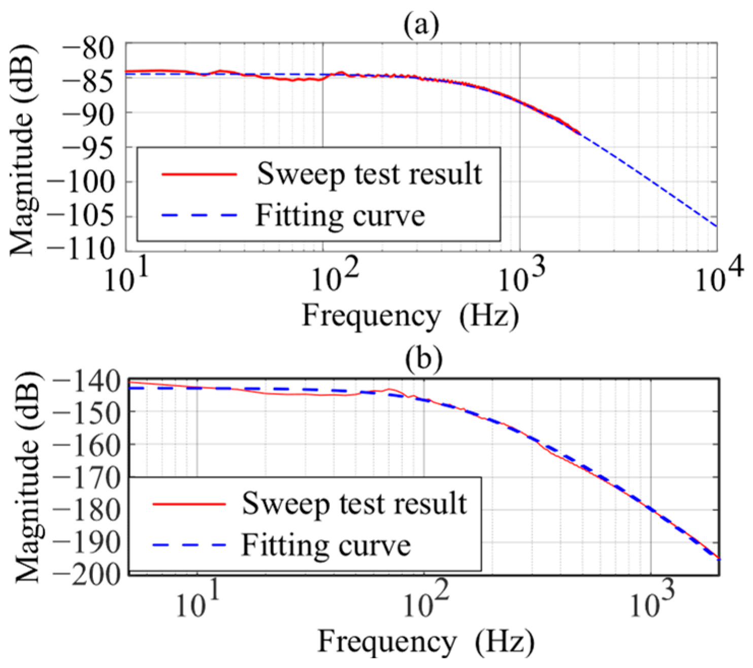
Following the methodology described in ref. [26], the power amplifier stage and the system dynamics are identified using a frequency-response-based experimental approach, as illustrated in Figure 9. A sinusoidal excitation signal is applied starting from 10 Hz. For each excitation frequency, the input is maintained until transient responses sufficiently decay and the system output reaches steady state. Steady-state conditions are judged by observing the convergence of the displacement amplitude and phase over multiple consecutive excitation cycles. Once steady state is achieved, response data are recorded at measurement points (A, B, and C) over several steady-state periods to ensure reliable frequency-response extraction. To reduce the influence of measurement noise and flow-induced disturbances, repeated measurements are performed at each frequency point, and the final frequency-response data are obtained by averaging. Since steady-state sinusoidal excitation is employed, no additional windowing is applied. The excitation frequency is then incremented in 5 Hz steps and applied continuously up to 2000 Hz until sufficient data are obtained to characterize the system dynamics over the frequency range. The nominal model of the system is then simplified into the following empirical form [19]:
G n s = Λ 4 s 3 + Λ 1 s 2 Λ 2 s Λ 3
The parameters kωz, ωpz in Equation (3), as well as the parameters Λ1, Λ2, Λ3, and Λ4 in Equation (9), are system-dependent coefficients to be identified. A comparison between the identified model based on experimental data and the empirical model is shown in Figure 10, and the identified parameter values are summarized in Table 2.

3.3. Stability Analysis of the CDOB and Filter Design

Based on the identification results presented in Figure 10 and the system parameter uncertainty analysis in Section 3.1, the relationship between the controlled object and its uncertainties can be assumed as follows:
G o s = G n s 1 + Δ n s G a s = G ω s 1 + Δ ω s
where Δ denotes the multiplicative perturbation, while Δn and Δω represent the multiplicative uncertainties associated with Gn(s) and Gω(s), respectively.
For convenience of description, the disturbance observers constructed from the current and displacement signals in Figure 3 are referred to as DOB A and DOB B, respectively. And the necessary and sufficient condition for the stability of DOB A is given by [28]:
1 S A s Δ ω s 1
where SA(s) denotes the sensitivity function of the magnetic bearing control system based on DOB A. It is defined as 1 d ~ 1 / d . Combining Equations (7) and (10), the sensitivity function of DOB A can be expressed as:
S A s = 1 G a s G ω 1 s G L A s + G a s G ω 1 s 1 G L A s e d
In Equation (12), Gω(s) can be equivalently substituted for Ga(s), so that it can be simplified as SA(s) = 1 − GLA(s). Substituting the result into Equation (11) yields:
G L A s Δ ω s 1
Inequality Equation (13) serves as the prerequisite for ensuring the stability of DOB A and forms the fundamental basis for the design of the low-pass filter GLA(s). Similarly, for DOB B, the design constraint for GLB(s) can be derived as follows:
G L B s Δ n s 1 .
As shown in Figure 3, the output of the CDOB is the linear weighted sum of the outputs from DOB A and DOB B, structurally constituting a parallel configuration of DOBs. Based on the superposition principle of linear systems, provided that each individual DOB is stable, the overall stability of the parallel DOB structure remains unaffected. Therefore, the key to ensuring stability is designing the low-pass filters, which requires that G ω 1 ( s ) · G L A ( s ) and G n 1 ( s ) G L B ( s ) be realizable; the relative degree condition must be satisfied as follows:
deg d e n G L A deg n u m G L A + r e l . deg G ω deg d e n G L B deg n u m G L B + r e l . deg G n
where deg{·} denotes the polynomial degree, and rel.deg(·) represents the relative degree of a transfer function. Since the nominal plant Gω(s) consists only a first-order power amplifier, its relative degree is one, i.e., rel.deg(Gω) = 1. In contrast, the Gn(s) consists of a first-order power amplifier and a second-order mechanical subsystem, giving rel.deg(Gn) = 3. Therefore, to guarantee realizability and causality of the observer implementation, the denominator order of each filter must be at least equal to the sum of its numerator order and the relative degree of the corresponding nominal model.
To facilitate more straightforward tuning of the low-pass filter parameters, the adopted transfer function expressions for designing GLA(s) and GLB(s) are given as follows:
G L A s = 2 τ a s + 1 τ a 2 s + 2 τ a s + 1 G L B s = 4 τ b s + 1 τ b 4 s 4 + 4 τ b 3 s 3 + 6 τ b 2 s 2 + 4 τ b s + 1
Here, τa and τb are filter characteristic constants related to the cutoff frequencies of GLA(s) and GLB(s), respectively. In practice, τa and τb are selected on the order of the inverse of the desired observer bandwidth, providing a trade-off between disturbance tracking performance and noise amplification.

4. Simulation and Experimental Verification

Simulations were conducted to validate the effectiveness of the proposed method, with the simulation parameters detailed comprehensively in Table 2.

4.1. Robustness Analysis

Based on the CDOB structural block diagram shown in Figure 3, the sensitivity function of the magnetic bearing control system utilizing the CDOB approach is expressed as:
S s = 1 g o b G L A s + 1 g o b G L B s
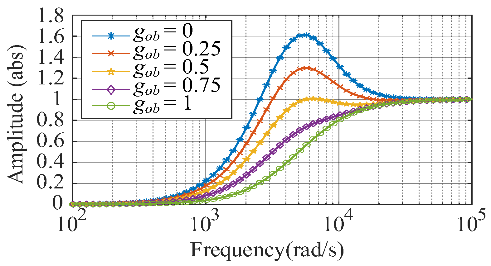
To ensure comparability in robustness analysis, the amplitude-frequency characteristics of GLA(s) and GLB(s) are deliberately matched in the low-frequency range, while maximizing the bandwidth of the CDOB by selecting τa = τb = 0.0003. The amplitude-frequency responses of the sensitivity function for different gain coefficients gob under varying conditions are illustrated in Figure 11. As shown, the maximum magnitude of the sensitivity function across the entire frequency range is approximately 1.62, which means the proposed CDOB method exhibits sufficient robustness to accommodate model uncertainties of the controlled object. Furthermore, as gob increases, the peak of the sensitivity function decreases; however, an excessively low peak may compromise the system’s dynamic performance. In practical engineering applications, parameter tuning can be performed based on actual requirements.

4.2. Performance Analysis of Disturbance Estimation

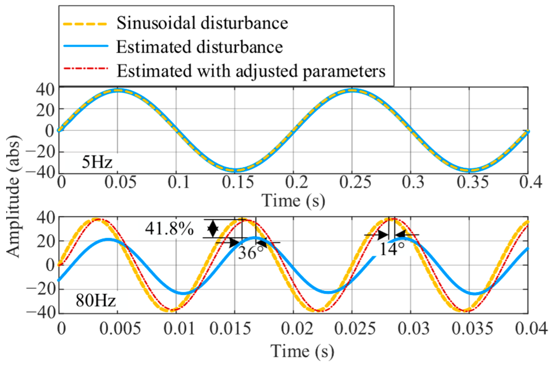
In the simulation study, a low-frequency sinusoidal disturbance is adopted as a representative input to qualitatively evaluate the disturbance estimation and rejection capability of the proposed CDOB. It is not associated with a specific physical flow rate. When gob = 0, the CDOB reduces to a conventional DOB. As illustrated in Figure 12, under a disturbance frequency of 5 Hz, the CDOB output closely tracks the original disturbance signal with negligible deviation. However, as the disturbance frequency increases to 80 Hz, the estimated signal exhibits an amplitude attenuation of approximately 41.8% and a phase lag of about 36°, resulting in a significant deviation between the observer output and the actual disturbance. This discrepancy severely compromises the accuracy of disturbance compensation. To enhance the system’s disturbance estimation capability, the low-pass filter parameters and observer output gain within the CDOB structure were further tuned in a targeted manner. After optimization, under the 80 Hz disturbance condition, the amplitude attenuation of the estimated signal was nearly eliminated, and the phase lag was reduced to approximately 14°, enabling high-precision disturbance tracking. These results demonstrate that the parameter-tuned CDOB achieves excellent disturbance estimation performance.
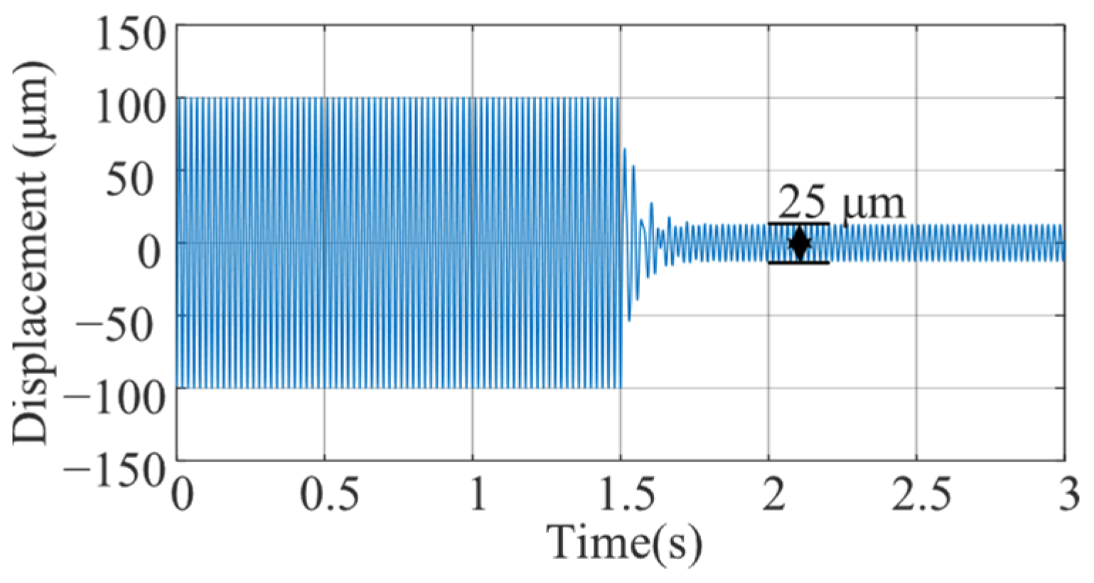
The simulation results of disturbance suppression are presented in Figure 13. At the initial time (0 s), a 50 Hz disturbance signal is introduced into the magnetic bearing rotor system, causing the rotor’s maximum vibration displacement to reach approximately 200 μm peak-to-peak. After implementing the proposed CDOB method at 1.5 s, the vibration peak-to-peak amplitude decreases to about 25 μm, effectively mitigating the impact of low-frequency external disturbances on the rotor’s suspension position. These results validate the effectiveness of the method proposed in this study.

4.3. Experiments

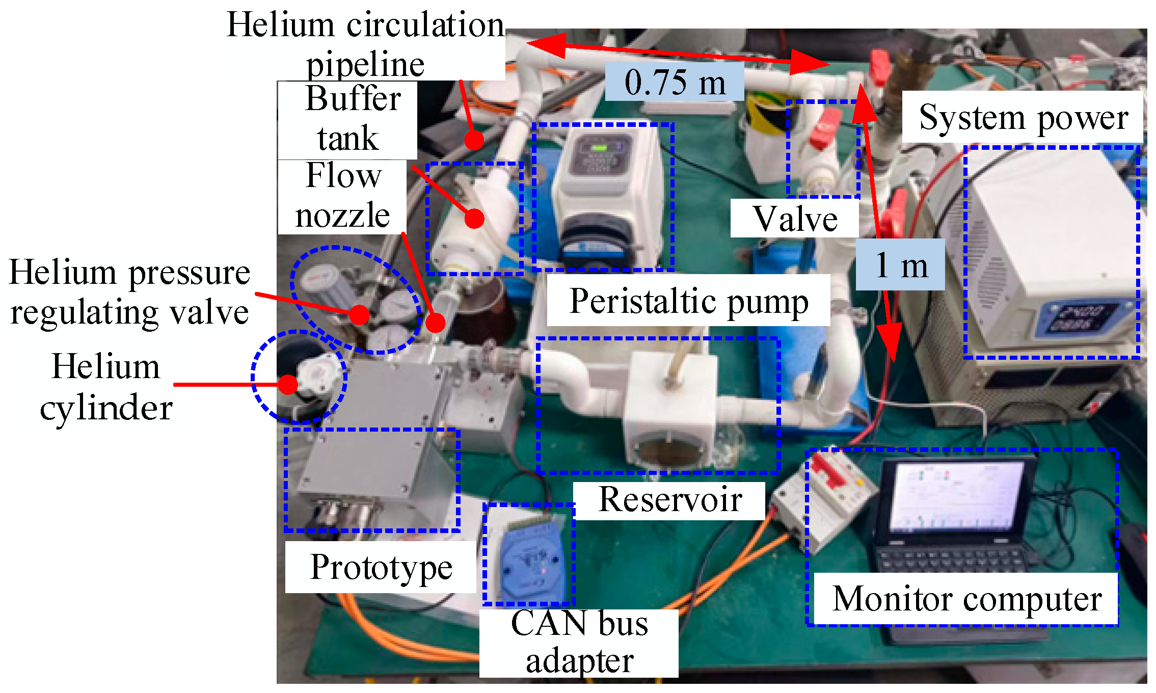
To experimentally validate the practical effectiveness of the proposed method, a dedicated test platform was constructed, as illustrated in Figure 14. The setup consists of a peristaltic pump, water circulation piping, a helium cylinder, a pressure regulation valve, helium circulation piping, a power supply, the test prototype, and a monitoring computer used to supervise pump operation and acquire rotor displacement signals in real time. In the experiments, helium gas was used as the working fluid to approximate the hydrogen recirculation environment while ensuring operational safety. The peristaltic pump used in the experiments is a BT100-2J model equipped with a YZ1515 pump head, with a volumetric displacement of 3.8 mL/rev and a speed control resolution of 0.1 r/min, resulting in a flow-rate uncertainty of ±0.38 mL/min. All experimental results presented in this study are obtained from raw displacement measurements, without applying any digital filtering or post-processing. The proposed CDOB algorithm was implemented on a TMS320F28335 digital signal processor, with a sampling frequency of 10 kHz and a PWM power amplifier switching frequency of 20 kHz. Signal acquisition was performed using the on-chip ADC of the DSP, which provides a 12-bit resolution with a reference voltage of 3 V.
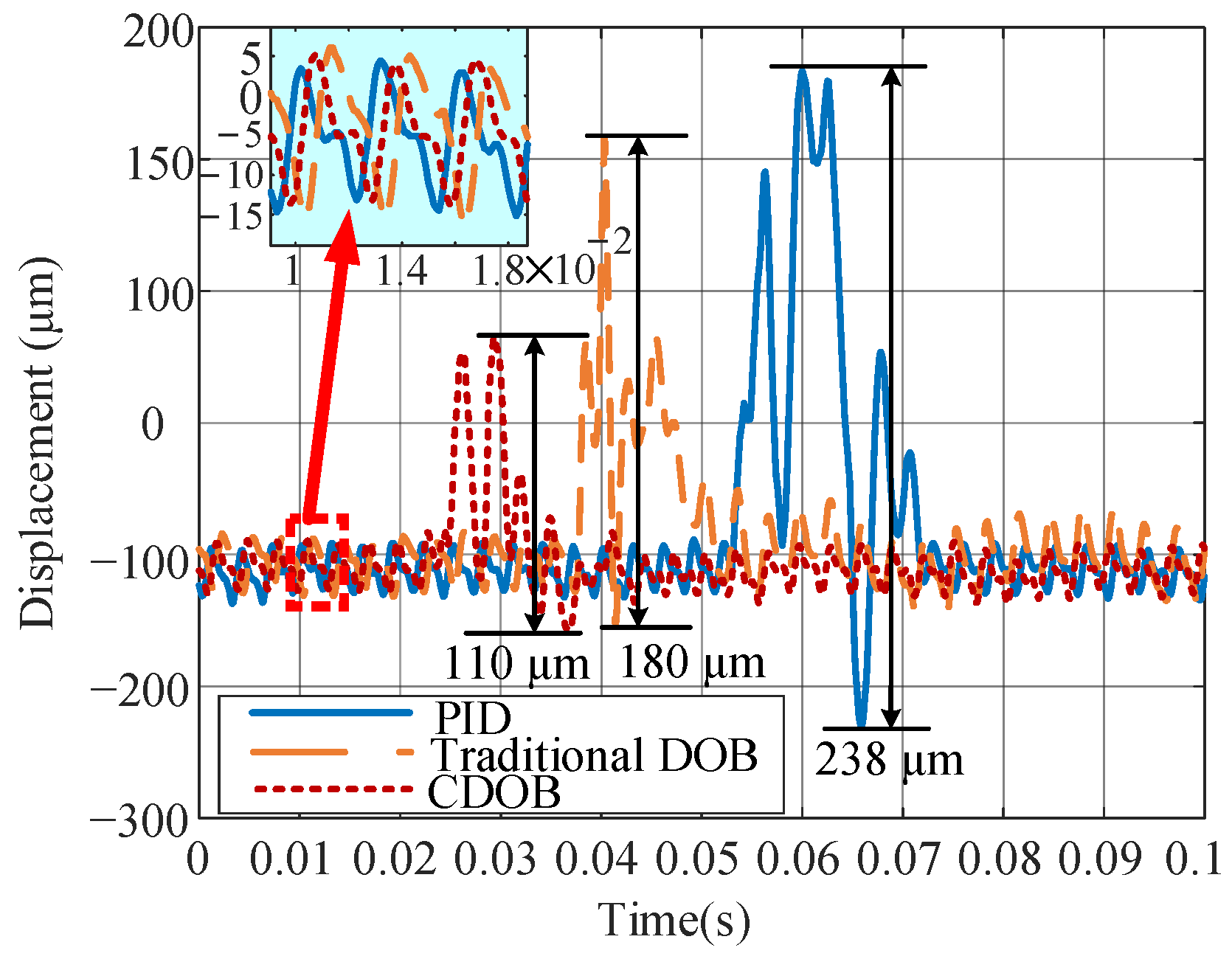
To ensure the consistency of hydraulic impact disturbances as much as possible, the peristaltic pump was adjusted to deliver a constant and appropriate flow rate. The effectiveness of different control algorithms in suppressing water-flow-induced impact disturbances was then evaluated, with the experimental results presented in Figure 15. At a rotor speed of 20,000 r/min, the axial displacement of the rotor exhibited a maximum peak-to-peak value of 238 μm under conventional PID control, under which the rotor system was highly susceptible to instability. With the introduction of a traditional DOB, the peak-to-peak axial displacement was reduced to 180 μm, showing significant improvement. Under the proposed CDOB method, the maximum peak-to-peak axial displacement further decreased to 110 μm. This represents a reduction of approximately 53.8% compared to PID control and about 38.9% compared to the traditional DOB approach, demonstrating a markedly improved capability in disturbance suppression.
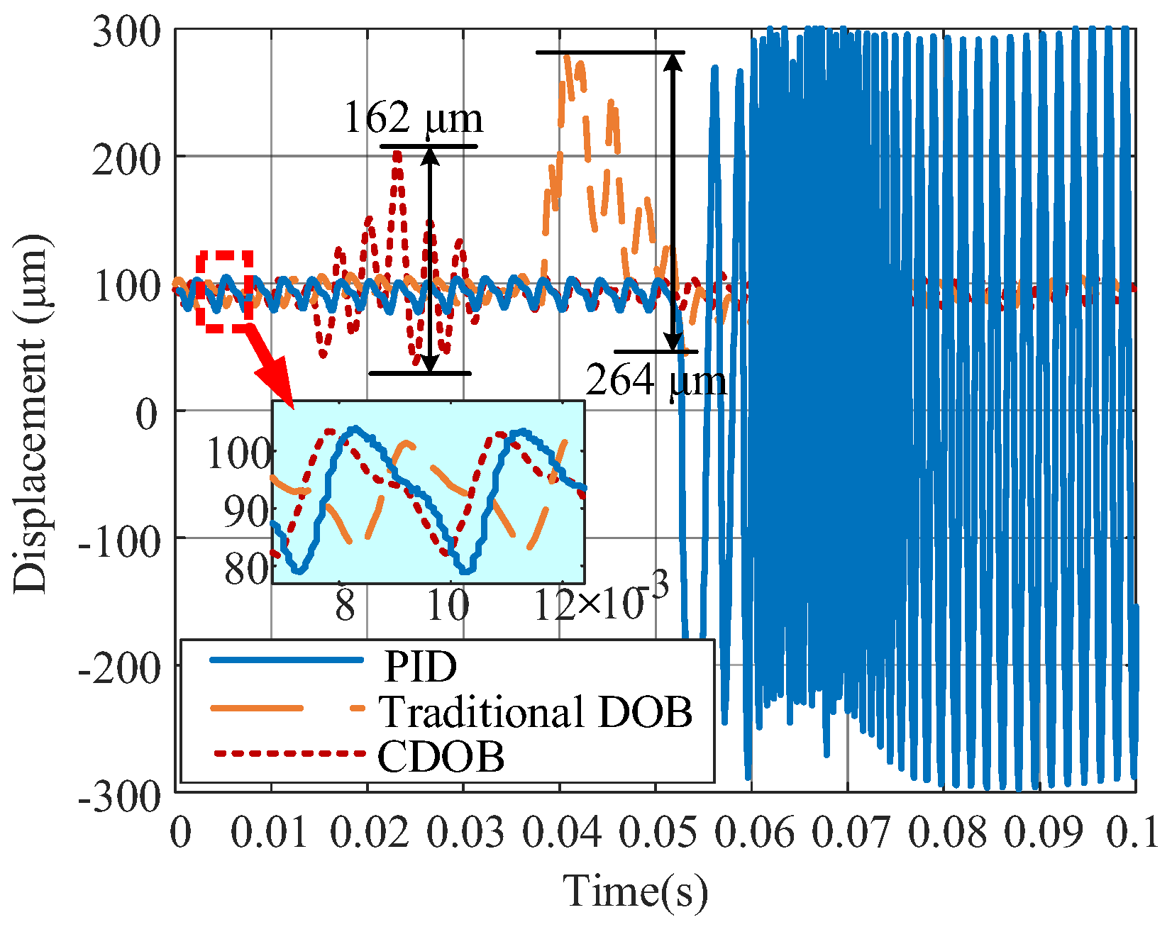
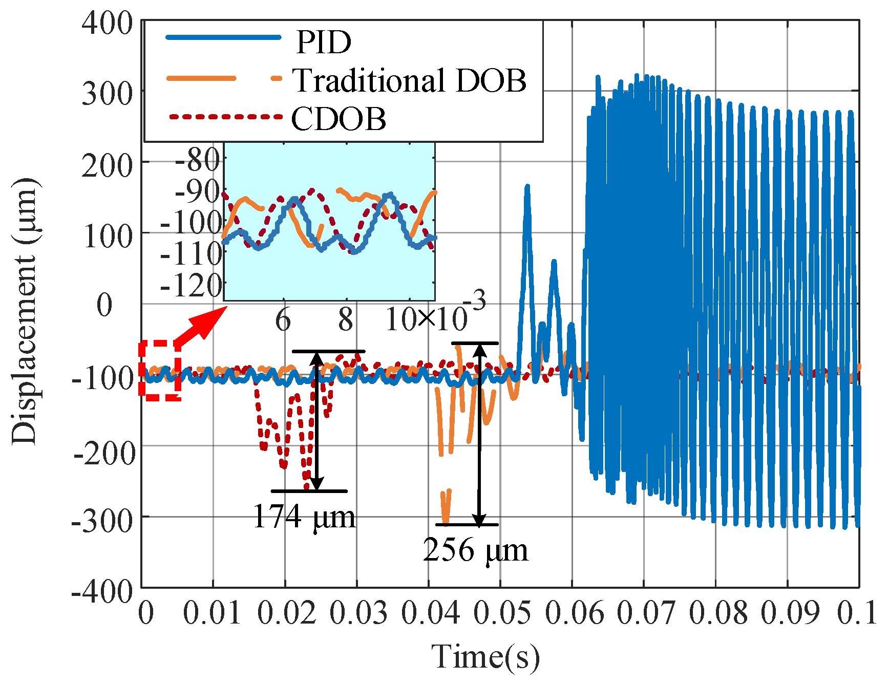
Furthermore, to evaluate the effectiveness of the proposed method in suppressing water-flow-induced impact disturbances under parameter perturbations, the reference position of the rotor center was intentionally offset by −0.1 mm and 0.1 mm, respectively. The axial levitation position of the rotor is detected and controlled in closed loop using an eddy-current displacement sensor. In the closed-loop control system, directional shifts of the rotor position can be achieved by adjusting the reference signal for the axial levitation position. The disturbance suppression performance under different control strategies was compared, with the corresponding results shown in Figure 16 and Figure 17. As illustrated in Figure 16, when the rotor center was offset by 0.1 mm, the rotor-impeller system became unstable under water-flow impact with only PID control, posing a significant risk under practical operating conditions. When the traditional DOB was employed, the peak-to-peak axial displacement decreased to 264 μm. In contrast, under the CDOB method, the maximum peak-to-peak axial displacement was further reduced to 162 μm, corresponding to a reduction of approximately 38.6% compared to the traditional DOB approach.
As shown in Figure 17, when the rotor center was offset by −0.1 mm, the impeller-rotor system also exhibited instability under water-flow impact when only PID control was applied. With the traditional DOB method, the peak-to-peak axial displacement was reduced to 256 μm. Under the proposed CDOB method, the maximum peak-to-peak axial displacement further decreased to 174 μm, representing a reduction of approximately 32.0% compared to the DOB approach. Based on the experimental results, it is evident that under conditions of system parameter variation, the CDOB method outperforms the traditional DOB strategy and significantly exceeds the performance of standalone PID control.
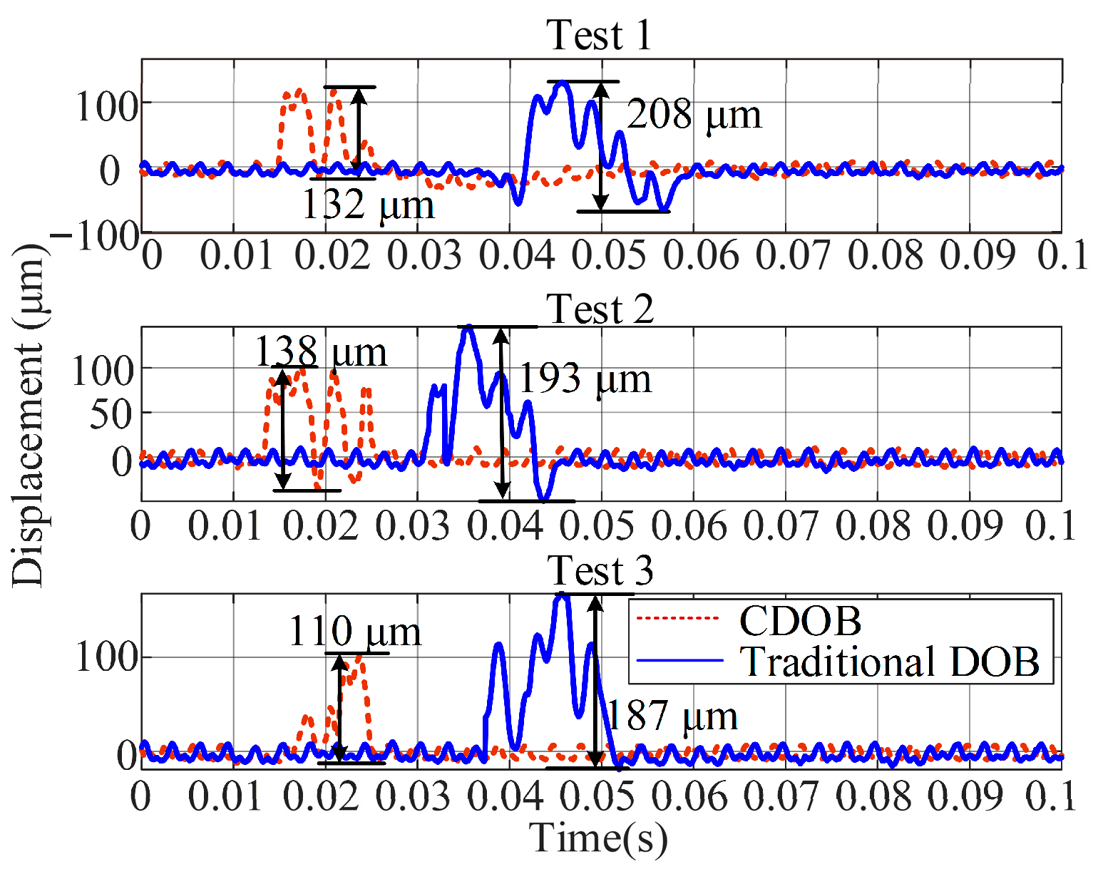
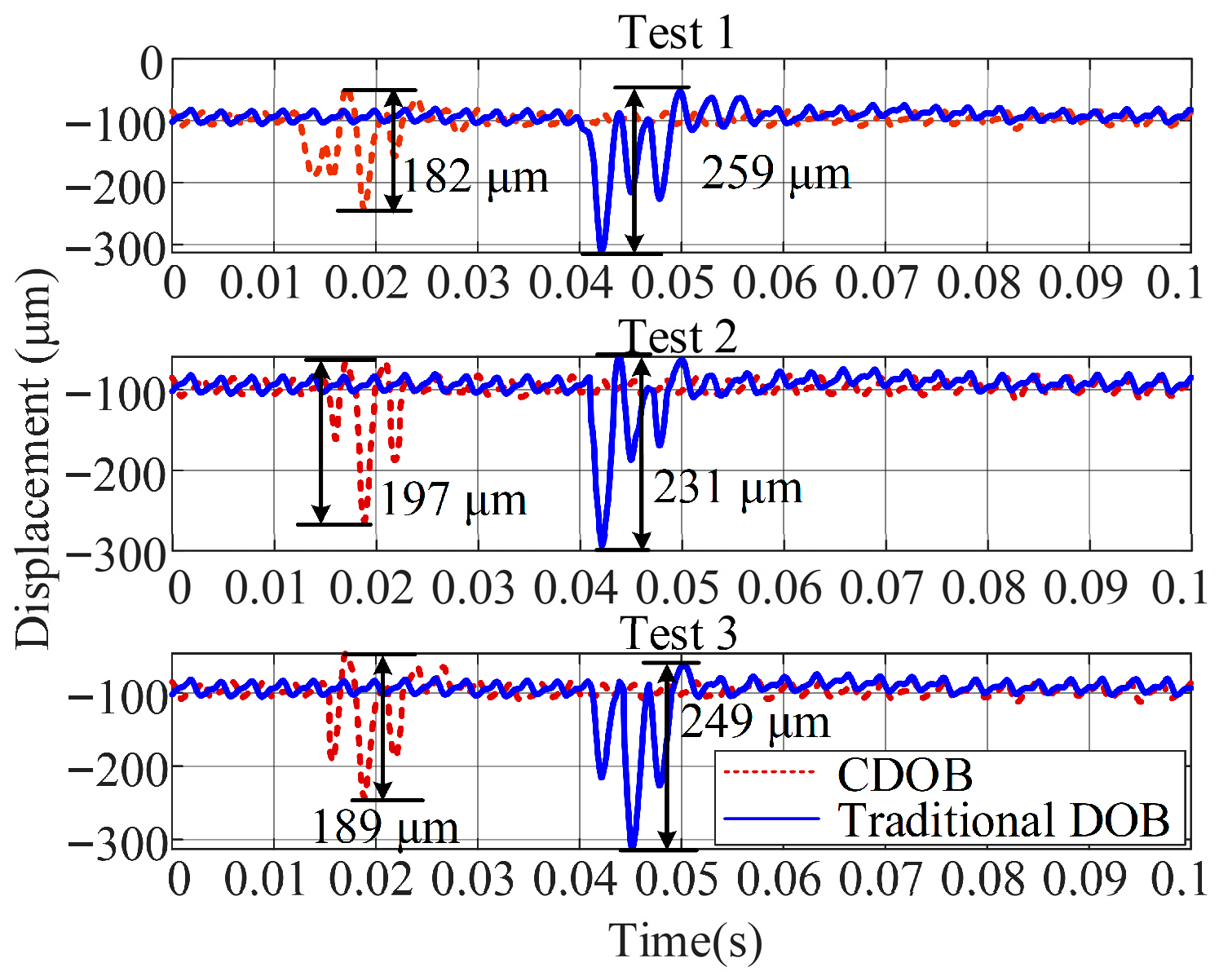
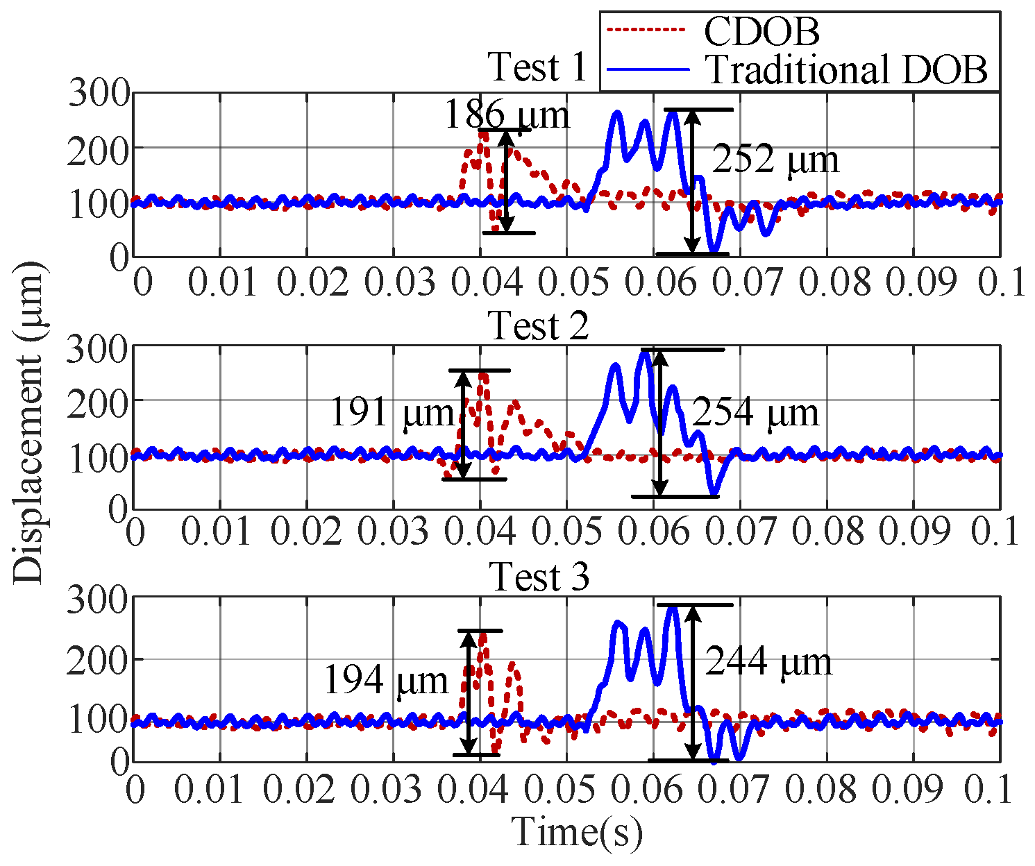
To further evaluate the effectiveness and repeatability of the proposed approach, three independent experiments were conducted at each levitation position considered in the previous tests, and the peak-to-peak axial displacement was adopted as the quantitative performance index. The corresponding results are shown in Figure 18, Figure 19 and Figure 20, representing the centered position, −100 μm offset, and +100 μm offset conditions, respectively.
As shown in Figure 18, when the rotor operates at the centered position, the proposed CDOB consistently yields significantly smaller peak-to-peak axial displacements than the traditional DOB across all repeated tests. On average, the CDOB achieves an axial displacement reduction of approximately 35%, indicating a substantial improvement in disturbance suppression capability under nominal operating conditions.
Under the −100 μm offset condition (Figure 19), the axial load disturbance becomes more pronounced due to the deviation from the nominal suspension position. Nevertheless, the proposed CDOB maintains stable performance and reduces the average axial displacement by approximately 23% compared with the traditional DOB, demonstrating its robustness against position-dependent parameter variations.
Similarly, for the +100 μm offset case (Figure 20), the CDOB continues to outperform the conventional DOB, achieving an average displacement reduction of approximately 24%. In addition, the relatively smaller standard deviation observed for the CDOB indicates improved consistency and robustness under asymmetric operating conditions.
It should be noted that some variability among repeated tests is inevitable due to the non-repeatable and stochastic nature of flow-induced disturbances. Despite this, the proposed CDOB consistently exhibits superior disturbance rejection performance over the traditional DOB at all tested axial positions. A statistical comparison of the peak-to-peak axial displacements, including mean values and standard deviations calculated directly from raw displacement signals without digital filtering, is summarized in Table 3.

5. Conclusions

This study proposes a cascade-structured disturbance observer (CDOB) for axial disturbance suppression in magnetically suspended rotors. To address the phase lag and amplitude attenuation issues inherent in conventional single-channel disturbance observers, the proposed approach fuses rotor displacement and bearing current information, and incorporates complementary disturbance observation channels. Experimental results indicate that the proposed CDOB consistently delivers superior disturbance suppression performance compared to conventional DOBs across different levitation positions and multiple repeated tests, with the average peak-to-peak axial displacement reduced by 23% to 35%. This significantly improves the accuracy of disturbance estimation and suppression, ensuring stable operation of magnetic bearing control systems under complex operating conditions.
The proposed cascade-structured architecture provides new design guidance for enhancing the disturbance rejection capabilities of conventional disturbance observers. Moreover, it is applicable to other precision mechatronic platforms that require reliable disturbance estimation and suppression under uncertain disturbances and time-varying operating conditions.

Author Contributions

Conceptualization, J.L. and J.Z.; methodology, J.L. and J.Z.; software, J.L.; validation, J.L.; resources, S.Z.; data curation, J.L.; writing—original draft preparation, J.L.; writing—review and editing, S.Z., J.L. and J.Z.; supervision, S.Z. and J.Z.; project administration, S.Z. and J.Z.; funding acquisition, S.Z. and J.Z. All authors have read and agreed to the published version of the manuscript.

Funding

This work was supported in part by the National Natural Science Foundation of China under Grant 62225301 and 62103022.

Data Availability Statement

Data used to support the findings of this study are included within this article.

Conflicts of Interest

The authors declare no conflicts of interest.

Abbreviations

The following abbreviations are used in this manuscript:
HFCHydrogen fuel cell
DOBDisturbance observer
CDOBCascade-structured disturbance observer
ESOExtended state observer
AMBActive magnetic bearing

References

  1. Gao, Y.; Lin, M. Research on the performance characteristics of hydrogen circulation pumps for PEMFC vehicles. Int. J. Hydrogen Energy 2024, 50, 1255–1272. [Google Scholar] [CrossRef] [Scilit]
  2. Han, J.; Feng, J.; Chen, P.; Liu, Y.; Peng, X. A review of key components of hydrogen recirculation subsystem for fuel cell vehicles. Energy Convers. Manag. X 2022, 15, 100265. [Google Scholar] [CrossRef] [Scilit]
  3. Wang, S.; Jin, D.; Zhang, Y.; Wang, K.; Gui, X. A forward-curved blade centrifugal compressor for anode recirculation in proton exchange membrane fuel cells. Int. J. Hydrogen Energy 2024, 53, 736–748. [Google Scholar] [CrossRef] [Scilit]
  4. Akhtar, J. Enhancing Electric Vehicle Performance and Battery Life Through Flywheel Energy Storage System: Modelling, Simulation, and Analysis; SAE Technical Paper; SAE International: Warrendale, PA, USA, 2024. [Google Scholar]
  5. Donati, G.; Basso, M.; Mugnaini, M.; Neri, M.O. Automatic tuning of augmented PIDs for active magnetic bearings supporting turbomachinery. IEEE/ASME Trans. Mechatron. 2024, 30, 1765–1775. [Google Scholar] [CrossRef] [Scilit]
  6. Ma, T.; Yang, Y.; Lin, W.; Yang, Y.; Jia, W.; Zhang, J. Design of a novel high-efficiency water separator for proton exchange membrane fuel cell system. Int. J. Hydrogen Energy 2019, 44, 5462–5469. [Google Scholar] [CrossRef] [Scilit]
  7. Wismer, S.E.; Jimenez, A.; Al-Douri, A.; Grabovetska, V.; Groth, K.M. PEM electrolyzer failure scenarios identified by failure modes and effects analysis (FMEA). Int. J. Hydrogen Energy 2024, 89, 1280–1289. [Google Scholar] [CrossRef] [Scilit]
  8. Li, S.; Yang, J.; Chen, W.-H.; Chen, X. Generalized extended state observer based control for systems with mismatched uncertainties. IEEE Trans. Ind. Electron. 2011, 59, 4792–4802. [Google Scholar] [CrossRef] [Scilit]
  9. Chen, W.-H.; Yang, J.; Guo, L.; Li, S. Disturbance-observer-based control and related methods—An overview. IEEE Trans. Ind. Electron. 2015, 63, 1083–1095. [Google Scholar] [CrossRef] [Scilit]
  10. Fan, Y.; Qiu, B.; Liu, L.; Yang, Y. Global fixed-time trajectory tracking control of underactuated USV based on fixed-time extended state observer. ISA Trans. 2023, 132, 267–277. [Google Scholar] [CrossRef] [Scilit]
  11. El-Sousy, F.F.; Amin, M.M.; Soliman, A.S.; Mohammed, O.A. Optimal adaptive ultra-local model-free control based-extended state observer for PMSM driven single-axis servo mechanism system. IEEE Trans. Ind. Appl. 2024, 60, 7728–7745. [Google Scholar] [CrossRef] [Scilit]
  12. Wang, X.; Ohnishi, W.; Koseki, T. Frequency response data based disturbance observer design: With application to a nonminimum phase motion stage. IEEE/ASME Trans. Mechatron. 2022, 27, 5318–5326. [Google Scholar] [CrossRef] [Scilit]
  13. Sun, Z.; Shao, S.; Zhang, Z.; Liu, J.; Tang, H.; Li, L.; Yuan, S. Pd sliding mode control of active suspension based on adaptive disturbance observer. Meas. Sci. Technol. 2025, 36, 076211. [Google Scholar] [CrossRef] [Scilit]
  14. Ruderman, M.; Iwasaki, M. Observer of nonlinear friction dynamics for motion control. IEEE Trans. Ind. Electron. 2015, 62, 5941–5949. [Google Scholar] [CrossRef] [Scilit]
  15. Rouhani, S.; Tsao, T.-C.; Speyer, J.L. Integrated MIMO fault detection and disturbance observer-based control. Mechatronics 2021, 73, 102482. [Google Scholar] [CrossRef] [Scilit]
  16. Jin, C.; Cao, Y.; Zhou, H.; Zhou, J.; Xu, Y.; Ye, Z.; Xin, Y. Research on composite hierarchical anti-disturbance strategy for magnetic bearing rotor using ∞ and observer. J. Vib. Control 2024, 30, 5603–5613. [Google Scholar] [CrossRef] [Scilit]
  17. Kuperman, A. Uncertainty and disturbance estimator-assisted control of a two-axis active magnetic bearing. Trans. Inst. Meas. Control 2016, 38, 764–772. [Google Scholar] [CrossRef] [Scilit]
  18. Sun, Z.; He, Y.; Zhao, J.; Shi, Z.; Zhao, L.; Yu, S. Identification of active magnetic bearing system with a flexible rotor. Mech. Syst. Signal Process. 2014, 49, 302–316. [Google Scholar] [CrossRef] [Scilit]
  19. Sun, M.; Zhou, J.; Dong, B.; Le, Y.; Zheng, S. Disturbance force self-sensing and suppression method for AMB-rotor system based on disturbance observer. IEEE Sens. J. 2020, 20, 9245–9252. [Google Scholar] [CrossRef] [Scilit]
  20. Noshadi, A.; Shi, J.; Lee, W.S.; Shi, P.; Kalam, A. System identification and robust control of multi-input multi-output active magnetic bearing systems. IEEE Trans. Control Syst. Technol. 2015, 24, 1227–1239. [Google Scholar] [CrossRef] [Scilit]
  21. Jiang, H.; Su, Z.; Wang, D.; Wu, C. Multiparameter identification for active magnetic bearing with uncertainties based on a coupled nonlinear model. IEEE Trans. Ind. Electron. 2022, 70, 10431–10441. [Google Scholar] [CrossRef] [Scilit]
  22. Garoli, G.Y.; Pilotto, R.; Nordmann, R.; de Castro, H.F. Identification of active magnetic bearing parameters in a rotor machine using Bayesian inference with generalized polynomial chaos expansion. J. Braz. Soc. Mech. Sci. Eng. 2021, 43, 552. [Google Scholar] [CrossRef] [Scilit]
  23. Yeh, T.-J.; Huang, C.-C.; Toh, C.-S. Closed-loop identification of multi-axis active magnetic bearing systems based on decentralized and decoupling control. Mechatronics 2023, 90, 102933. [Google Scholar] [CrossRef] [Scilit]
  24. Gautam, A.K.; Tiwari, R. Integrated analysis of additive and multiplicative internal excitation parameters in misaligned-bowed internally damped rotor systems with active magnetic bearings: Numerical and experimental identification. J. Sound Vib. 2025, 595, 118794. [Google Scholar] [CrossRef] [Scilit]
  25. Bleuler, H.; Cole, M.; Keogh, P.; Larsonneur, R.; Maslen, E.; Okada, Y.; Schweitzer, G.; Traxler, A.; Nordmann, R. Magnetic Bearings: Theory; Design, and Application to Rotating Machinery; Springer Science & Business Media: Berlin/Heidelberg, Germany, 2009. [Google Scholar]
  26. Han, X.; Liu, G.; Le, Y.; Dong, B.; Zheng, S. Unbalanced magnetic pull disturbance compensation of magnetic bearing systems in MSCCs. IEEE Trans. Ind. Electron. 2022, 70, 4088–4097. [Google Scholar] [CrossRef] [Scilit]
  27. Le, Y.; Sun, J.; Han, B. Modeling and design of 3-DOF magnetic bearing for high-speed motor including eddy-current effects and leakage effects. IEEE Trans. Ind. Electron. 2016, 63, 3656–3665. [Google Scholar] [CrossRef] [Scilit]
  28. Kempf, C.J.; Kobayashi, S. Disturbance observer and feedforward design for a high-speed direct-drive positioning table. IEEE Trans. Actions Control Syst. Technol. 1999, 7, 513–526. [Google Scholar] [CrossRef] [Scilit]
Figure 1. Structure of the magnetically levitated hydrogen recirculation pump.
Energies 19 00911 g001
Figure 2. Basic DOB block diagram.
Energies 19 00911 g002
Figure 4. Modular block diagram of the CDOB implementation.
Energies 19 00911 g004
Figure 5. Simulation results: (a) rotor position and force; (b) rotor position and displacement stiffness.
Energies 19 00911 g005
Figure 6. Simulation results: (a) current and force at different rotor positions; (b) current and current stiffness at different rotor positions.
Energies 19 00911 g006
Figure 7. Effects of Kxz and Kiz variations on the magnetic suspension rotor model (simulation). (a) Bode plots under different Kiz values; (b) Bode plots under different Kxz values. (Orange, nominal parameter; blue, decreased parameter; yellow, increased parameter.)
Energies 19 00911 g007
Figure 8. Impact of rotor position on the power amplifier: (a) rotor position versus coil inductance; (b) Bode plots of the power amplifier at different rotor positions.
Energies 19 00911 g008
Figure 9. AMB system identification block diagram.
Energies 19 00911 g009
Figure 10. Identification results: (a) power amplifier model; (b) plant model.
Energies 19 00911 g010
Figure 11. Equivalent sensitivity function of the CDOB.
Energies 19 00911 g011
Figure 12. CDOB tracking performance under sinusoidal disturbance.
Energies 19 00911 g012
Figure 13. Sinusoidal disturbance rejection performance of the CDOB.
Energies 19 00911 g013
Figure 14. Experimental test system.
Energies 19 00911 g014
Figure 15. Disturbance suppression at the centered position by different methods.
Energies 19 00911 g015
Figure 16. Disturbance suppression with a 0.1 mm rotor offset by different methods.
Energies 19 00911 g016
Figure 17. Disturbance suppression with a −0.1 mm rotor offset by different methods.
Energies 19 00911 g017
Figure 18. Repeated experimental comparison of axial displacement responses at the centered position (0 μm).
Energies 19 00911 g018
Figure 19. Repeated experimental comparison of axial displacement responses at an axial offset of −100 μm.
Energies 19 00911 g019
Figure 20. Repeated experimental comparison of axial displacement responses at an axial offset of +100 μm.
Energies 19 00911 g020
Table 1. Nominal Parameters of the hydrogen recirculation pump.
ParametersValues
Rated power/W600
Input voltage/V24
Working point pressure ratio1.11
Maximum speed/rpm120,000
Overall quality/kg4.2 kg
Table 2. Parameters of the system.
SymbolValueSymbolValue
m0.086 kgkωz0.0055
kp0.0005ωpz103
ki0.05Λ1110
kd0.01Λ21.756 × 10⁴
kf0.0002Λ31.809 × 10⁶
gob0.7Λ45.373 × 10³
Table 3. Comparison of repeated experimental results.
Axial PositionCDOB Mean ± Std (μm)DOB Mean ± Std (μm)
0 μm126.7 ± 14.5196.0 ± 10.7
−100 μm189.3 ± 7.5246.3 ± 14.1
+100 μm190.3 ± 4.0250.0 ± 5.3
Disclaimer/Publisher’s Note: The statements, opinions and data contained in all publications are solely those of the individual author(s) and contributor(s) and not of MDPI and/or the editor(s). MDPI and/or the editor(s) disclaim responsibility for any injury to people or property resulting from any ideas, methods, instructions or products referred to in the content.