Article

An Adaptive-Feedforward Power Decoupling for Grid-Forming Converters with Pre-Synchronization via Sliding-Mode Control


1
China Southern Power Grid Technology Co., Ltd., Guangzhou 510080, China
2
School of Future Technology, Shandong University, Jinan 250061, China
*
Authors to whom correspondence should be addressed.
Energies 2026, 19(3), 784; https://doi.org/10.3390/en19030784
Submission received: 12 November 2025 / Revised: 11 January 2026 / Accepted: 16 January 2026 / Published: 2 February 2026
(This article belongs to the Special Issue Advanced Grid Integration of Photovoltaic Energy Systems)

Abstract

The grid-forming (GFM) converter is an effective solution for grid support. However, mode switching failures and power coupling challenges in weak grids pose significant safety risks. To address these challenges, an adaptive feedforward power decoupling method with pre-synchronization is proposed to achieve seamless switching and accurate power regulation without line impedance information. First, based on a small-signal model of the GFM converter, a power coupling coefficient considering the power control loop is presented to analyze the coupling mechanism. Second, a reactive power adaptive compensation channel is constructed, in which a sliding mode (SM) compensation controller is designed in the reactive power loop, to dynamically correct the voltage reference and achieve power decoupling. The proposed method achieves wide-range dynamic decoupling control without line impedance parameters, exhibiting strong grid adaptability. Third, an improved pre-synchronization strategy based on the SM controller is developed, which leads the virtual power to converge to zero, to ensure seamless switching between islanded and grid-connected modes. Finally, the effectiveness of the proposed method is validated through simulation and experimental results.

1. Introduction

Growing environmental challenges and the pursuit of carbon neutrality are driving the rapid expansion of renewable energy, such as photovoltaic generation [1]. However, the inherent volatility of renewable generation leads to a reduction in system inertia and damping, which ultimately jeopardizes grid stability [2,3].
In response, the virtual synchronous generator (VSG) has received increasing attention over the past decades, because it could emulate the characteristics of synchronous generators and provide rotational inertia support to the grid [4]. VSG technology contributes to power regulation and system stability, helping maintain a power balance and stable operation in power systems [5,6]. Thus, as the typical form, grid-forming (GFM) converters based on VSG control present an attractive solution for enhancing power system inertia and damping [7,8,9].
In general, the GFM converter is designed for both islanded and grid-connected modes [10]. Before the GFM converter switches from the islanded to the grid-connected mode, the amplitude and phase of converter voltages must be consistent with those of grid voltages. Otherwise, it can lead to current surges or power oscillations [11,12]. Additionally, in weak grids, the line impedance ratio R/X is large and non-negligible. The line resistance has a pronounced impact on the coupling between active power and reactive power, leading to inaccurate control or even instability [13]. Thus, pre-synchronization and power decoupling control are two key challenges in the development of the GFM converters.
For pre-synchronization, obtaining phase and frequency information is the key. The conventional method is to use the phase-locked loop (PLL) [14,15,16]. However, it does not accommodate periodic phase jumps inherent in a proportional–integral (PI) controller regulating the phase discrepancy [17]. To improve performance, a dual-PLL pre-synchronization unit is proposed to detect grid and inverter voltage phase angles, with a PI regulator controlling the phase difference [18]. However, it not only increases control complexity but also is not suitable for the grid fault condition. Then, the pre-synchronization strategies based on a virtual power or current have been developed, eliminating the PLL [19,20]. The synchronization stability of parallel GFM converters during the pre-synchronization of an additional converter is studied, and P–f droop design guidelines are provided to prevent loss of synchronism of the existing converters [21]. Moreover, the virtual power-based method superimposes a virtual power signal onto the prime mover input of a VSG to achieve microgrid synchronization [22]. However, the sinusoidal relationship between virtual active power and the phase difference introduces multiple solutions for synchronization. It leads to the problem that, even when the virtual active power is zero, the phase difference could be non-zero at that instant.
In addition, decoupled control of active and reactive powers has been classified as follows: the virtual power method [23,24], the feedback compensation method [25,26], and the virtual impedance method [27,28]. The virtual power approach employs a relative gain matrix associated with the impedance angle to construct a virtual power [23] and virtual frequency [24] for power decoupling. However, the virtual power method only considers the resistance-to-reactance ratio (R/X) of line impedance, resulting in a poor decoupling performance. The feedback compensation method achieves decoupling by setting variable feedback, which estimates the voltage at the point of common coupling and tracks its reference value [25]. A full-state feedback control method is proposed to eliminate the power coupling, which retains the capability of inertia response [26]. However, its performance relies heavily on accurate identification of the power angle.
Moreover, virtual impedance is introduced to address power coupling issues caused by line impedance [27,28], but it focuses on eliminating power coupling caused by large power angles. An optimal virtual impedance-based power decoupling control strategy is proposed, to achieve steady-state power decoupling and ensure power oscillation damping [29]. A control strategy combining a virtual inductor and virtual capacitor is proposed, which successfully mitigated reactive power fluctuations [30]. However, methods based on virtual impedance have limited adaptability, while both the virtual power and feedback compensation approaches depend on accurate identification of line impedance parameters. Thus, accurate and rapid reactive power control remains a significant challenge, constraining system stability.
Thus, an adaptive feedforward power decoupling method with pre-synchronization is proposed, using a sliding mode controller, achieving grid connection and precise power control without requiring prior line impedance knowledge. The main contributions of this paper are as follows:
(1)
To achieve a grid-connected mode from the islanded mode for the GFM converter, a virtual reactive power-based pre-synchronization strategy is proposed, eliminating the need for a PLL. By overcoming the multi-solution asynchronization issue, the proposed strategy employs an SM controller to ensure precise voltage and frequency alignment prior to grid connection, enabling a seamless mode transition.
(2)
To enhance power control capability without the line impedance information, an adaptive power decoupling control strategy based on reactive voltage compensation is proposed. By analyzing the power coupling mechanism using the model with the coupling coefficient, an adaptive compensation channel via the SM controller is constructed that dynamically adjusts the output voltage reference to effectively suppress power coupling. The proposed method achieves robust power decoupling, demonstrating the satisfactory adaptability and the practical applicability with various line impedance conditions.
The remainder of this paper is organized as follows. In Section 2, the model of the GFM converter is given. Section 3 describes the design process of the proposed method. In Section 4, simulation and experimental results are given. Finally, the conclusion is presented in Section 5.

2. Materials and Methods

2.1. The Operation Mode Switching Analysis of GFM Converters

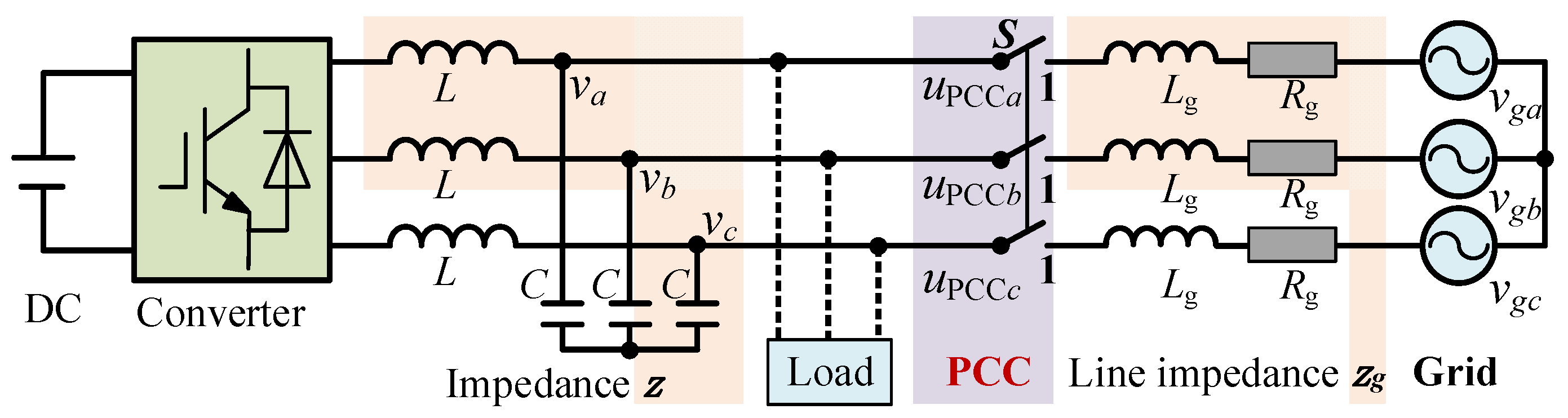
The circuit configuration of the GFM converter is shown in Figure 1. vi represents the grid voltage (i = a, b, c), Zg is the line impedance, and Rg and Lg are the resistance and inductance of the line impedance, respectively. L and C are the filter inductance and filter capacitance, respectively. uPCCi is the output voltage at the point of common coupling (PCC), ei is the grid voltage, and ia, ib, and ic are the three-phase output currents.
In both grid-connected and islanded operation modes, the control of the GFM converter consists of the VSG control and voltage-current loop control. This unified control structure avoids switching between different control strategies during mode transitions. The VSG realizes the power control through the active power–frequency and reactive power–voltage relationship, which simulates the rotor mechanical equation and rotor voltage equation [5]. The corresponding control equations are expressed as
J d ω d t = P n P D p ( ω ω n ) E = K q ( Q n Q ) + E n ,
where Pn and Qn are the nominal active and reactive power references, respectively, P and Q denote the actual active and reactive output powers of the VSG, Dp is the virtual damping coefficient, Kq is the droop coefficient, J is the active virtual moment of inertia, ω is the output angular frequency, E is the output voltage amplitude of GFM converters, ωn is the nominal angular frequency, and En is the voltage reference.
When switching from grid-connected to islanded mode, the output power of the GFM converter needs to equal the load demand, without power supplied from the grid. Otherwise, voltage and current surges may occur. Thus, it is essential to reduce the grid power to zero before mode switching. The output power of the GFM converter is gradually adjusted to align with the required power in the islanded mode. Once the grid no longer supplies power to the load, it becomes equivalent to disconnection, ensuring seamless switching.
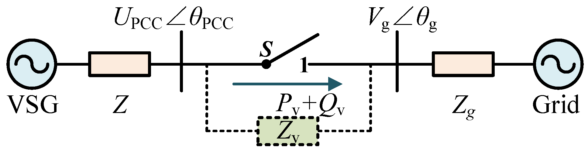
When switching from island to grid-connected mode, to avoid current surges during the switching process, pre-synchronization control should be applied to eliminate the phase and amplitude differences between the output voltage of the GFM converter and the grid voltage. As shown in Figure 2, in order to achieve the synchronization of the voltage of the GFM converter with the grid voltage, a virtual impedance Zv = sLv + Rv is introduced between the GFM converter and the grid. Upcc and θpcc represent the voltage amplitude and phase at the PCC, respectively. Vg and θg are the voltage amplitude and phase of the grid, respectively. The virtual power Pv and Qv can be expressed as
P v = 1 Z v U pcc cos θ pg V g 2 cos α v + U pcc V g sin θ pg sin α v Q v = 1 Z v U pcc cos θ pg V g 2 sin α v U pcc V g sin θ pg cos α v ,
where αv is the virtual impedance angle, and θpg = θpccθg.
The virtual impedance amplitude Zv and the virtual impedance angle αv can be expressed as [22]
Z v = ω L v 2 + R v 2 α v = arctan ω L v R v
From (2), it can be seen that the virtual power has a sinusoidal relationship with the phase difference. If the αv is arbitrary, the synchronized angle in the pre-synchronization process could yield a multi-solution or non-solution. In such cases, although the virtual active power reaches zero, the phase difference in the voltage across the virtual impedance is nonzero, and then the pre-synchronization process fails.

2.2. Small-Signal Model and Power Coupling

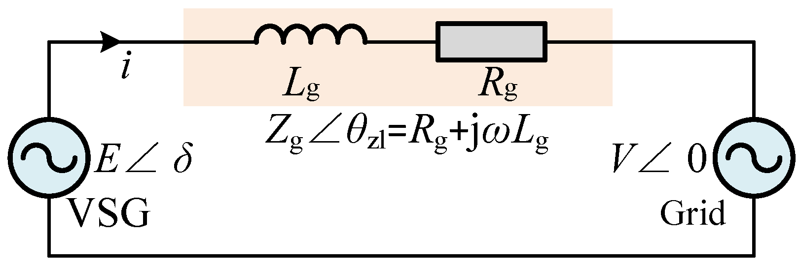
The equivalent circuit of a GFM converter connected to the grid is shown in Figure 3. Here, Eδ is the output voltage of the GFM converter, V∠0 is the grid voltage, i is the output current, and θzl is the line impedance angle. According to the relationship of the power flow, the output power of the GFM converter can be expressed as
P = E Z g E cos θ zl V cos ( θ zl + δ ) Q = E Z g E sin θ zl V sin ( θ zl + δ ) ,
To analyze the mechanism of power coupling, a small-signal model is established by linearizing the system dynamics around the steady-state operating point. When injecting small perturbations into (1) and ignoring the high-frequency components, the small-signal model can be expressed as
K ω = 1 J s + D p K E = K q ,
where Kω is the open-loop transfer function of VSG active power control, and KE is the open-loop transfer function of VSG reactive power control.
The power angle δ is calculated from the output voltage angular frequency ω and the grid voltage angular frequency ωg, expressed as
δ = ( ω ω g ) d t ,
The small-signal model of the VSG consists of steady-state and dynamic components in (5). However, the steady-state characteristics have attracted significant attention. Then, neglecting dynamic processes, the steady-state small-signal model in the control loop can be expressed as
K δ = 1 D p s ,
where Kδ is the active power-power angle open-loop transfer function of VSG.
The small-signal model of power flow can be obtained using the partial derivative calculations from (4), which can be expressed as
Δ P Δ Q = M 11 M 12 M 21 M 22 Δ δ Δ E = M Δ δ Δ E ,
In the operating state x0, the expression of M can be expanded as [27]
M 11 = V E 0 Z g sin ( θ zl + δ 0 ) M 12 = 2 E 0 Z g cos θ zl V Z g cos ( θ zl + δ 0 ) M 21 = V E 0 Z g cos ( θ zl + δ 0 ) M 22 = 2 E 0 Z g sin θ zl V Z g sin ( θ zl + δ 0 ) ,
where the δ0 is the steady-state power angle.
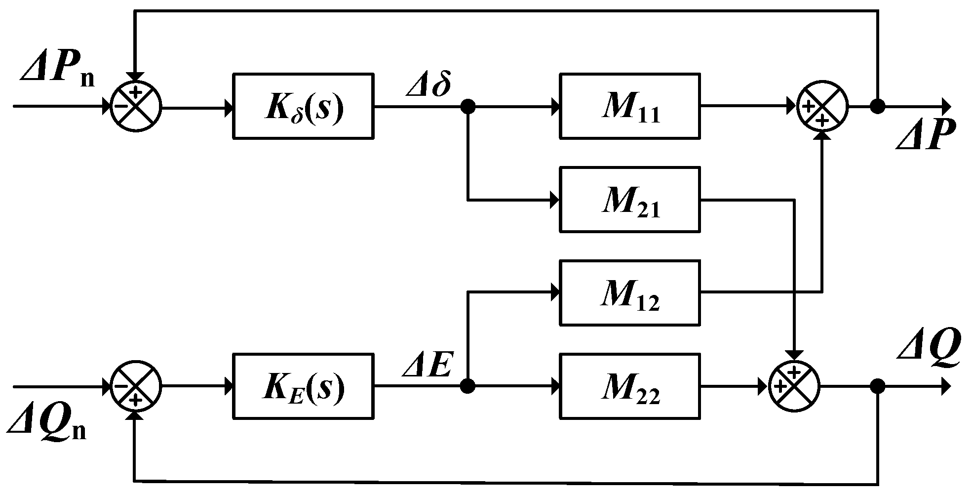
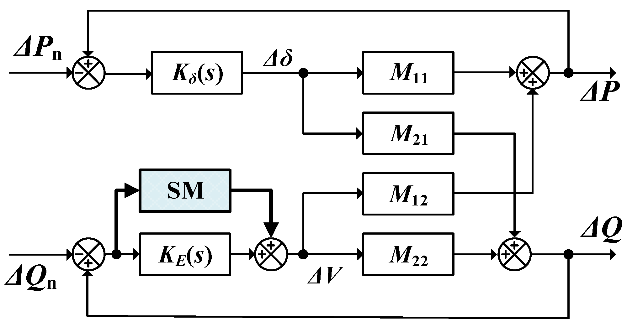
Combined with (7) and (8), the overall small signal model is shown in Figure 4. It can be observed that the power coupling problem is inevitable in practice. Generally, the line impedance exhibits inductive–resistive characteristics, and the power angle is not sufficiently small, resulting in a severe power coupling issue.

3. Proposed Adaptive Feedforward Power Decoupling Method with Pre-Synchronization

3.1. Quantitative Analysis of Power Coupling

In order to quantitatively analyze the power coupling impact, an extended power coupling coefficient matrix is presented, which incorporates closed-loop dynamics to analyze power coupling characteristics. Specifically, two feedback loops, the reactive power control loop and the active power control loop, are introduced to the power coupling coefficient. From (1), the expressions of the two feedback loops can be expressed as
Δ E = K q Δ Q Δ δ = Δ P / ( D p s ) ,
Based on the feedback loops described in (10), when the power reference is subjected to a disturbance, the perturbation behavior of the power flow can be effectively approximated by a small-signal model M that considers both the voltage–reactive power and power angle–active power feedback mechanisms. It can be expressed as
Δ P = M 11 D p s Δ P M 12 K q Δ Q Δ Q = M 21 D p s Δ P M 22 K q Δ Q ,
Simplifying the above formula, when the power reference value changes, the power coupling coefficients ξ1 and ξ2 can be expressed as
ξ 1 ξ 2 = Δ Q Δ P Δ P Δ Q = 1 M 11 M 21 ( 1 + M 22 K q ) M 12 K q   1 M 22 M 12 ( 1 + M 11 D p s ) M 21 D p s ,
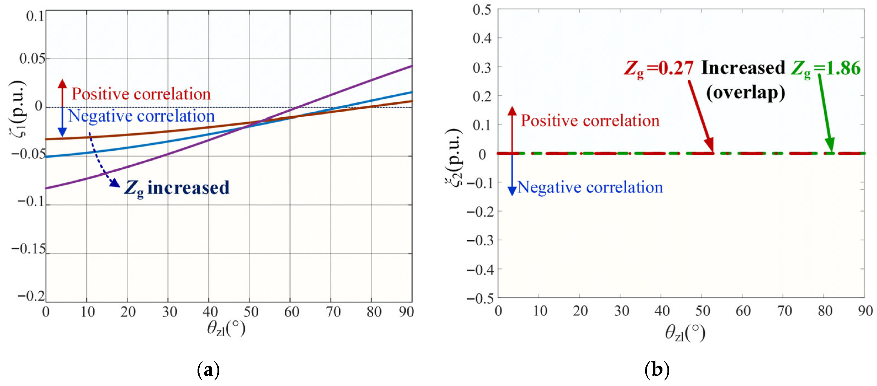
The characteristics of active power coupling and reactive power coupling can be effectively analyzed through the coupling coefficients ξ1 and ξ2, where the coupling coefficient is correlated with the power coupling impact. Specifically, as the coefficient approaches zero, the power coupling impact decreases. When the coupling coefficient is greater than zero, it indicates that the influence of power coupling is in the positive direction. Otherwise, when the coupling coefficient is less than zero, it indicates that the influence of power coupling is in the negative direction.
Then, the curves of the coupling degree coefficients ξ1 and ξ2 when the line impedance changes are drawn, as shown in Figure 5. As the impedance angle increases, the reactive power coupling coefficient ξ1 gradually decreases in Figure 5a. In addition, when line impedance Zg increases, the reactive power coupling coefficient ξ1 decreases, and the impact of power coupling increases in Figure 5b. Thus, regardless of Zg, the coupling effect of active power on reactive power still exists.
Instead, when the impedance angle is 50°, the active power coupling coefficient ξ2 is 0 p.u. (point B) in Figure 5b. In other words, if the reactive power output of the GFM converter is 5 kvar, no coupled active power (0 W) will be generated. Regardless of the value of Zg, the active power coupling coefficient ξ2 remains zero. It demonstrates that reactive power control has a negligible influence on active power, which is related to the integral term in the active power control loop.
Thus, the main influencing factor of power coupling is the effect of active power control on reactive power, while the effect of reactive power on active power is relatively small and can be largely ignored. The effect of active power control on reactive power is significantly influenced by the R/X as well as the power angle.

3.2. The Adaptive Power Decoupling Method via the Sliding Mode Control

When active power is disturbed, the fluctuation of the reactive power ΔQd is influenced by the power angle [26], which can be expressed as
Δ Q d = E Z g E sin θ zl V sin ( θ zl + δ ) E sin θ zl + V sin ( θ zl + δ + Δ δ ) ,
When the impedance angle θzl is 90°, the small-signal model (13) can be simplified as
Δ Q d = E V Z g sin θ zl + δ + Δ δ sin θ zl + δ E V Z g cos θ zl + δ Δ δ = E V Z g s i n δ Δ δ = P Δ δ ,
Since active power is not influenced by power coupling, the actual power output P can be replaced by the active power reference Pn to simplify the model. Then, the voltage fluctuation can be rewritten as
Δ E d = Δ Q d D p = P n Δ δ D p ,
Clearly, by compensating for the amplitude fluctuation of the voltage ΔEd, the influence of active power on reactive power can be suppressed. However, the calculation of Δδ is complex and depends on line impedance parameters. Then, the compensation for ΔEd has limitations in suppressing reactive power fluctuations.
Next, an adaptive feedforward power decoupling method is proposed, as shown in Figure 6, which is easy to apply in engineering and improves the power decoupling capability.
A sliding mode (SM) controller is introduced into the reactive power control loop, superimposing the reactive power error onto the reference voltage output. Δδ can be obtained by multiplying the reactive power error ΔQr and the sliding mode controller fSM. Since Dp and Pr are constants, the voltage compensation term ΔEc can be further simplified, and it can be expressed as
Δ E c = P n D p f SM ( Δ Q Δ Q n ) = G SM Δ Q ,
where GSM is the improved SM controller.
The proposed method retains the original reactive power control loop, while introducing a voltage compensation channel in parallel. After compensation by adaptive reactive power control, the voltage and reactive power feedback loop is modified as follows:
Δ E = ( K q + G SM ) Δ Q ,
Then, when the disturbance of the reference is introduced, the revised small-signal model M of the power flow can be approximated, which can be expressed as
Δ P = M 11 Δ δ M 12 ( K q G SM ) Δ Q Δ Q = M 21 Δ δ M 22 ( K q G SM ) Δ Q ,
Thus, the new reactive power coupling coefficient ξ1u is updated via the SM-based power decoupling method, which can be expressed as
ξ 1 u = 1 M 11 M 21 + M 11 M 22 M 21 ( K q G SM ) M 12 ( K q G SM ) ,
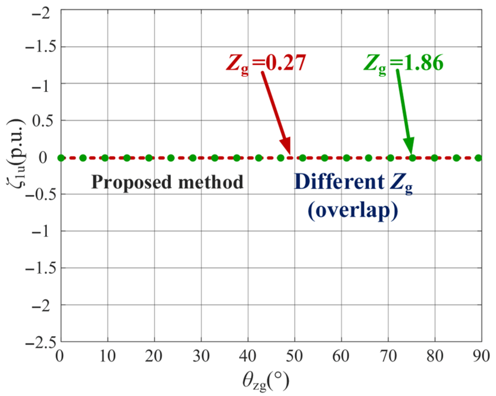
The power coupling coefficients under various active power and impedance conditions are presented in Figure 7. When the proposed power decoupling method is applied, the coupled reactive power remains at 0 p.u. despite variations in active power reference and line impedance, which demonstrates a satisfactory decoupling performance. Since the proposed method does not rely on the state of operating points or line impedance parameters, it exhibits significant practical value for engineering applications.

3.3. The Improved Pre-Synchronization via the Sliding Mode Control

When the virtual impedance angle αv = π/2, virtual power can be rewritten as
P v = U pcc U g sin θ pg Z v Q v = U pcc cos θ pg U g 2 Z v ,
From (20), it can be obtained that the phase difference is zero when the virtual reactive power is zero. Furthermore, for any phase angle difference, the direction of reactive power convergence toward zero aligns with that of phase angle difference convergence toward zero. Therefore, the virtual impedance angle αv should be set to π/2, implying that the virtual inductance Lv replaces the virtual impedance, without virtual resistance.
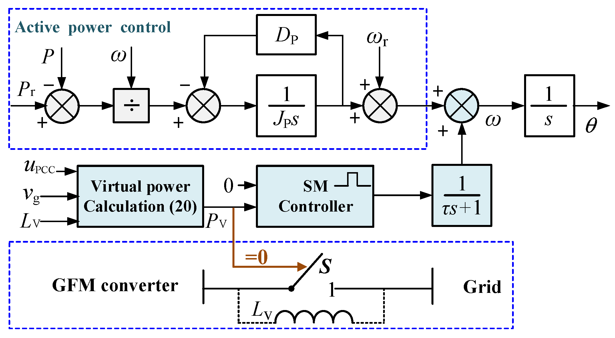
Then, the improved pre-synchronization strategy is proposed, including the angular frequency compensation loop and an amplitude compensation loop. This paper focuses on angular frequency compensation, and the control block is shown in Figure 8. When operating in the grid-connected mode, set the switch S to off, and the GFM converter disconnects the grid-connected (islanded) mode. When switching from islanded mode to grid-connected mode, the GFM converter adjusts the frequency through virtual active power. When the virtual active power is zero, the voltage phases on both sides of the switch S reach synchronization. Then, close the switch S to achieve seamless switching.
The SM control, as an exceptionally robust control method, effectively handles uncertainties and external disturbances even with a simple structure. Therefore, the SM controller could ensure a higher efficiency, reduce chattering, and avoid overestimation when compared with a PI controller. The SM controller for pre-synchronization is introduced, which achieves virtual active power to zero. The adaptive sliding mode controller is designed as follows:
s ˙ = u = k 1   |   s   |   s g n ( s ) ,
where k1 is the adjustment coefficient and is a constant.
With the sliding variable, s is designed as
s = e Q + k 2 0 t e Q ,
where eQ is the tracking error, and k2 is the positive parameter.
The adaptive controller design is shown in (21). Since the controller design is continuous, the control input automatically decreases as the sliding variable converges, thereby avoiding overestimation while reducing the amplitude to suppress chattering. The sliding surface employs a second-order design, which features a simple structure and is more suitable for applications in converters.
Since the virtual current does not exist in practice, the range of virtual inductance is relatively wide. When the virtual inductance Lv is small, the pre-synchronization process can be completed quickly, but it will lead to large virtual currents, causing voltage and current surges. Moreover, a small inertial link is added after the SM controller to smooth an instantaneous adjustment surge.

3.4. Stability Performance Analysis

As with most nonlinear control approaches, the stability analysis of SM control should be conducted using the Lyapunov stability theory. For the improved pre-synchronization strategy, choose the Lyapunov function as
V = 1 2 s 2 ,
Then, in order to prove the stability or progressive stability of an SM control system, it is necessary to verify that the derivative of V is negative or negative semi-definite. The expression is as follows:
V ˙ = s s ˙ = k 1 s   |   s   |   s g n ( s ) = k 1 s 2 0 ,
Therefore, since k1 is a positive parameter, s will gradually converge to 0. As can be seen from the design of the sliding variables in (22), when s → 0, it can be expressed as
e ˙ Q = k 2 e Q ,
This means the tracking error eQ will also gradually converge to zero.
Similarly, the proposed power decoupling method based on the SM controller is progressively stable. To achieve the desired control performance under the proposed sliding mode controller, the parameter selection should be based on comprehensive consideration. If k1 is set too small, the sliding mode condition cannot be satisfied, and the system trajectory cannot be attracted to the sliding surface. The response will exhibit steady-state error or slow oscillations, with poor robustness. If k1 set too large, although the system response will be very fast, it will introduce severe high-frequency chattering. The control output will switch violently between peaks and troughs at high frequencies, potentially damaging the overall system structure. If k2 is set too low, the system response becomes sluggish, requiring a long time to converge to a steady state. If k2 is set too large, the system may oscillate as it approaches a steady state.

3.5. Control Diagram of the Proposed Method

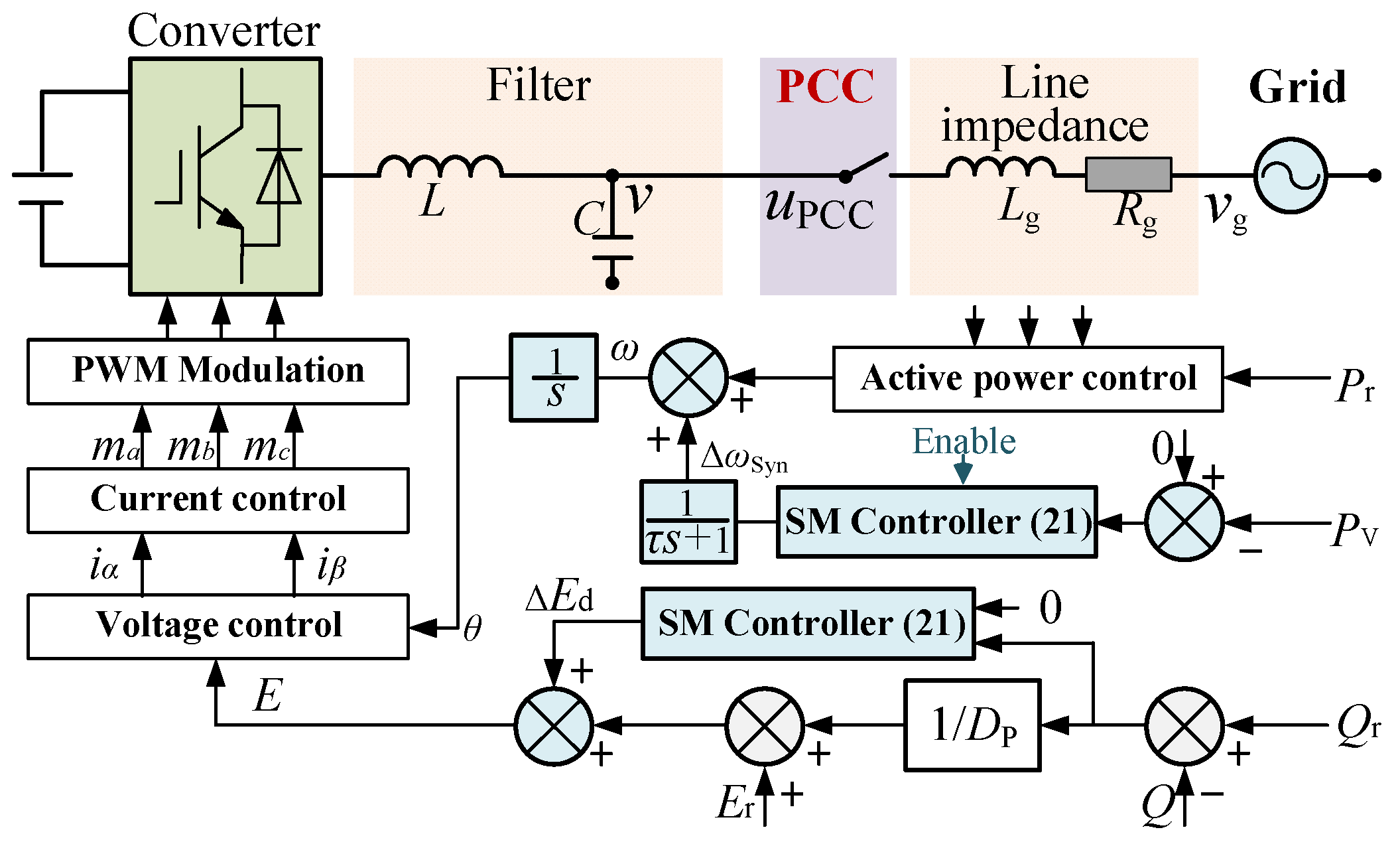
The overall control block diagram of the proposed power decoupling method with pre-synchronization via the SM control is illustrated in Figure 9, and it is summarized as follows:
(1)
For pre-synchronization control, frequency regulation is implemented in parallel within the active power control loop. The virtual active power of the virtual inductor is calculated, and then the SM controller tracks the desired virtual power reference, which is set to zero (0 W), to achieve phase synchronization and enable seamless switching.
(2)
For power decoupling control, the reactive power loop incorporates a decoupling compensation mechanism, in which a parallel-structured SM controller is employed to achieve closed-loop regulation of voltage amplitude. By compensating for voltage amplitude deviations to correct reactive power output errors, the GFM converter maintains effective power decoupling characteristics, improving the power control accuracy.
Furthermore, avoiding the dependency on line impedance parameters and complex mathematical computations means the proposed decoupling method has a low computational burden and straightforward implementation of the GFM converter. Moreover, the proposed method can be extended to other types of converters.
To explore the advantages of power decoupling offered by the proposed method, a comparison of various power decoupling methods is summarized in Table 1. Both the virtual inductor and virtual power methods require line impedance information from the grid, which limits the ability to decouple power. The feedback compensation method requires accurate power information; otherwise, inaccurate data can lead to a decline in performance. In contrast, the proposed method does not require either impedance or power information, and it demonstrates better robustness in terms of power decoupling.

4. Simulation and Experimental Results

To verify the effectiveness of the proposed power decoupling method with pre-synchronization, a GFM converter simulation and an experimental platform are established for both grid-connected and islanded modes, covering various scenarios.

4.1. The Simulation Verification

The simulation is built in the MATLAB/Simulink (v2020a) environment. The parameters for the simulation are shown in Table 2.

4.1.1. Pre-Synchronization Process Analysis

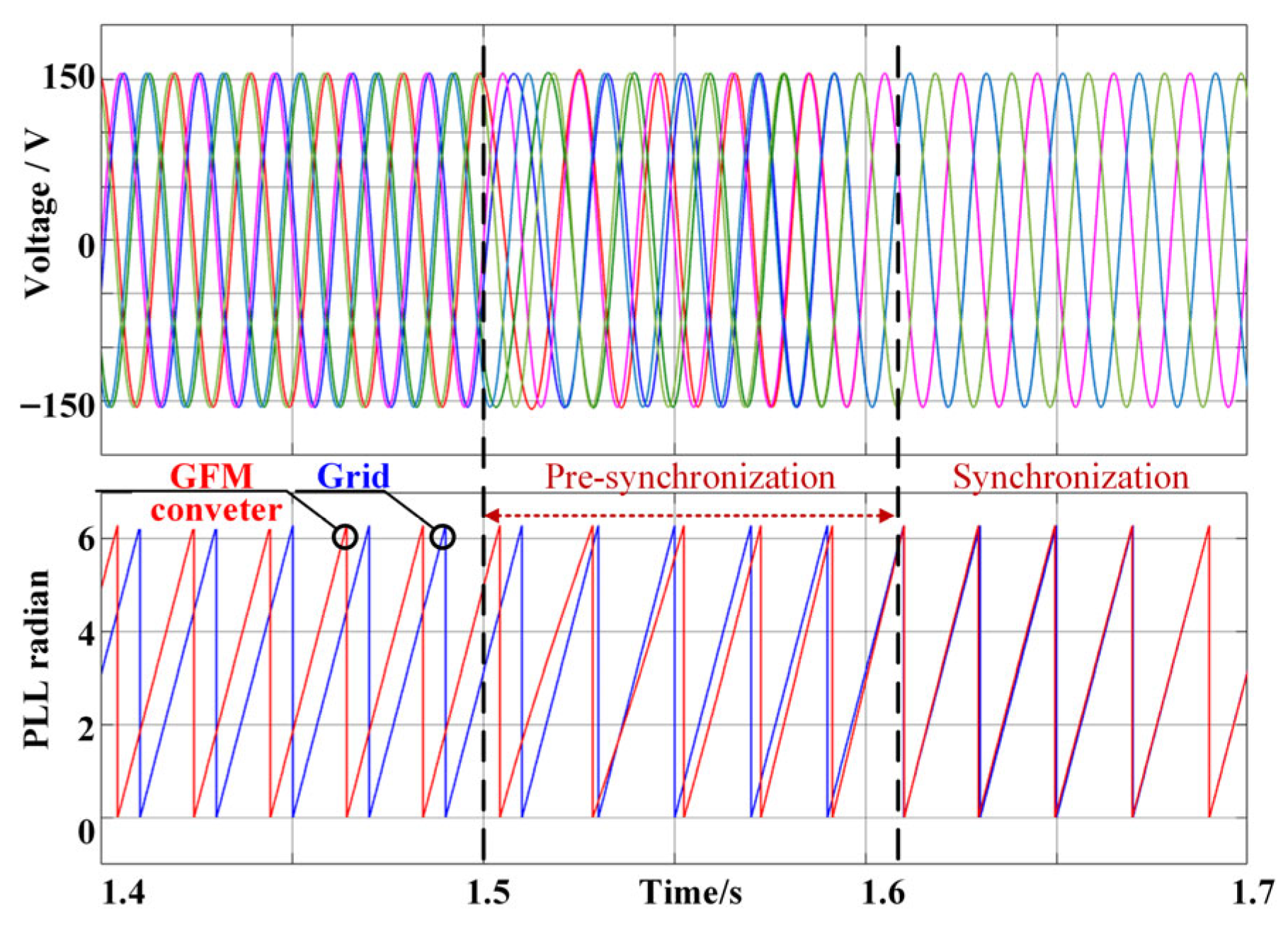
The simulation waveforms of the pre-synchronization are shown in Figure 10. The GFM converter operates in the islanded mode, initially supplying power to the local load. During this stage (t < 1.5 s), there is a large phase difference (almost 0.5π rad) between the voltage of the GFM converter and the grid. When the improved pre-synchronization is activated at 1.5 s, the phase difference and error begin to diminish gradually without any transient inrush voltage. After five cycles, the phase difference is reduced to nearly zero, indicating that the voltage of the GFM converter has successfully synchronized with the grid, which ensures a smooth switching process.

4.1.2. Power Decoupling Analysis

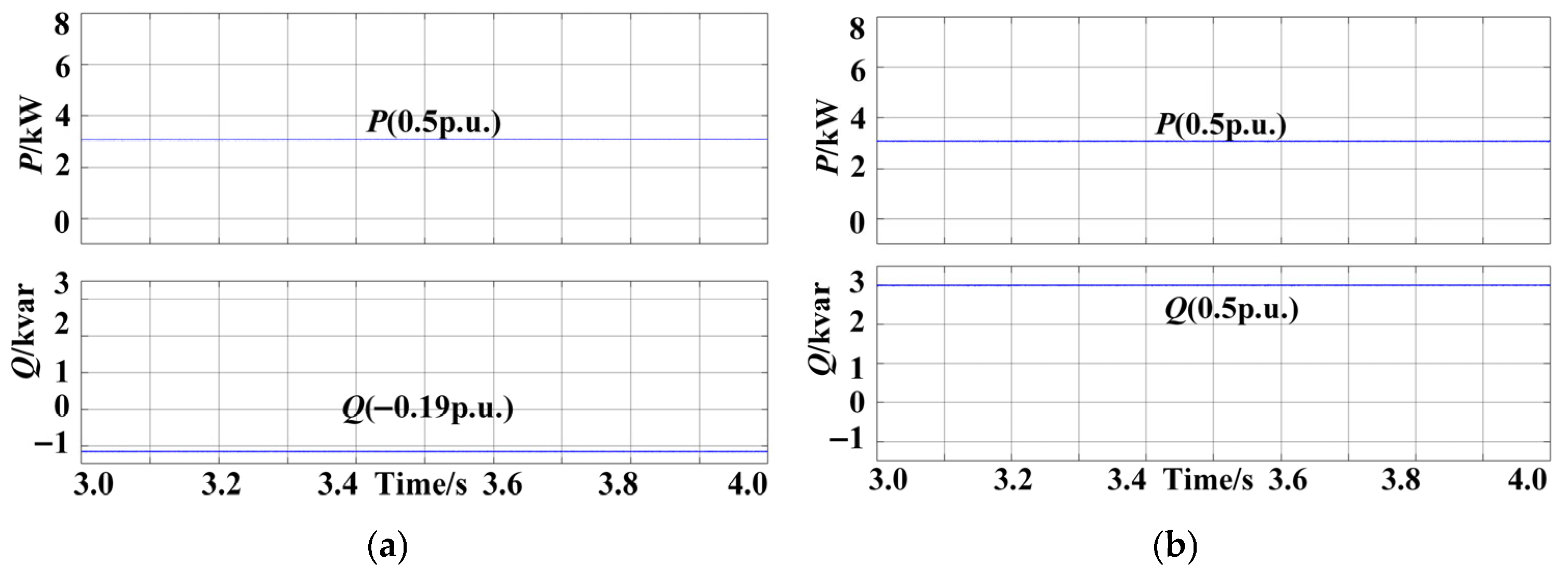
The simulation waveforms under a power reference of 3 kW/3 kvar (0.5 p.u./0.5 p.u.) are presented in Figure 11. Q is almost −0.19 p.u. and P is 0.5 p.u., where only the VSG control method is applied, as shown in Figure 11a. It can be observed that the impact of reactive power on active power is weak, which differs from the impact of active power on reactive power. In contrast, the power coupling is suppressed once the proposed method is implemented. P is 3 kW and Q is 3 kvar in Figure 11b, which is consistent with the references. The simulation results demonstrate that the proposed method has a better power decoupling control capability in a weak grid.
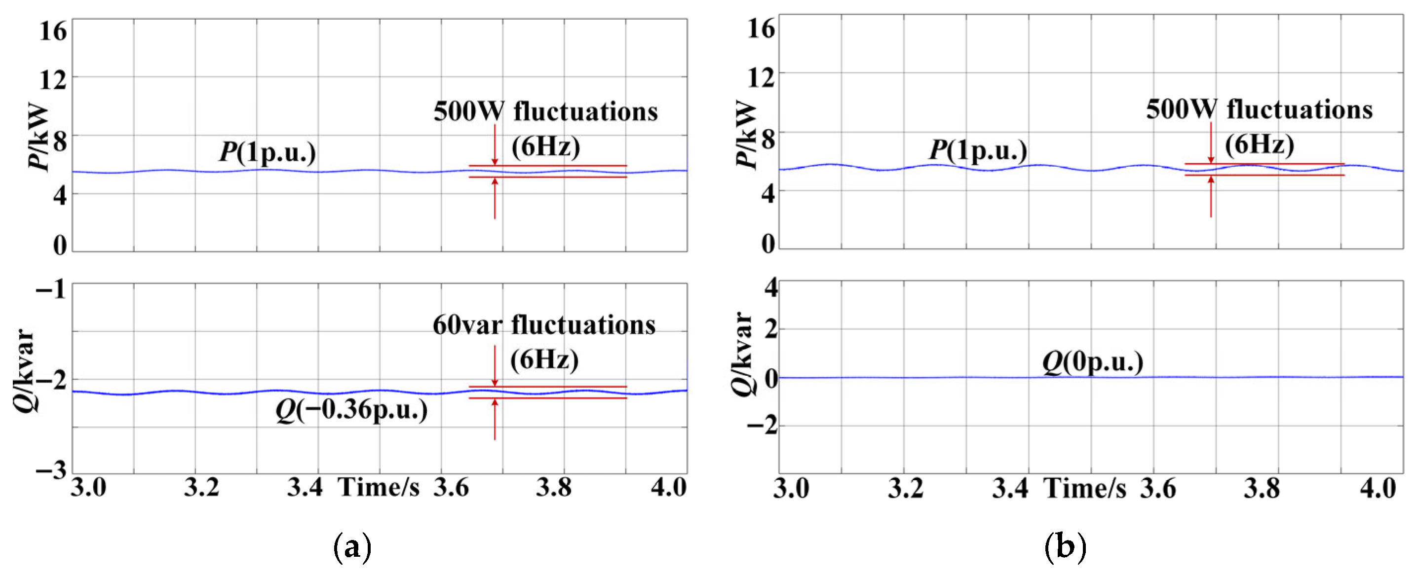
Moreover, the simulation waveforms under the power references of 6 kW/0 var with 500 W/6 Hz fluctuations are presented in Figure 12. The reactive power Q is almost −0.36 p.u. with fluctuations (peak–peak value is 60 var), indicating significant steady-state power coupling. In contrast, the proposed power decoupling method demonstrates a precise power control performance. As shown in Figure 12b, the output power P remains 6 kW, while Q is precisely maintained at 0 var, confirming the robustness to active power disturbances.

4.2. The Experimental Results

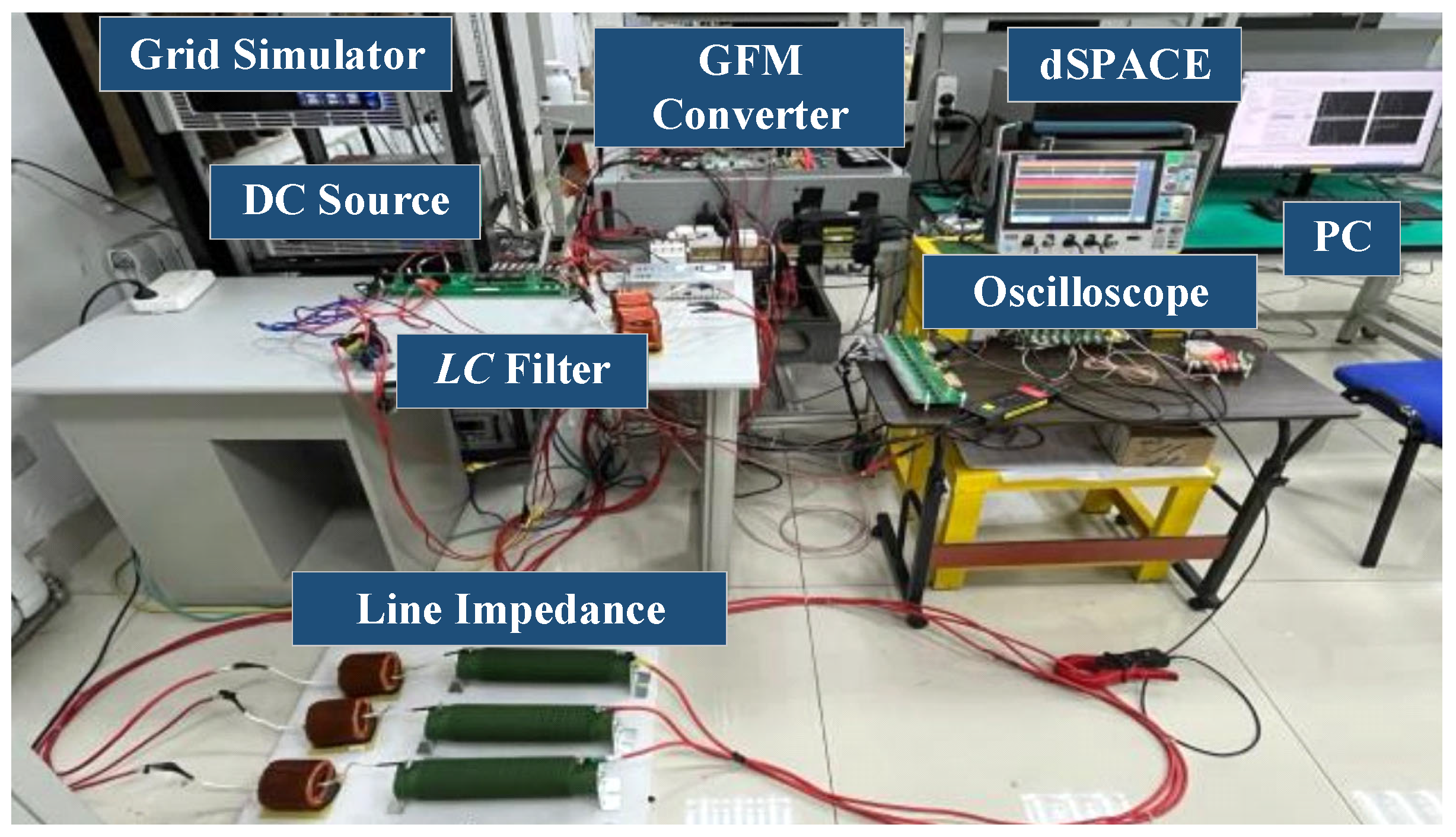
To further validate the effectiveness of the proposed method, an experimental platform for the GFM converter is established, as shown in Figure 13. The main experimental parameters are the same as the simulation. The GFM converter system comprises a main power circuit with driver circuits (the three-phase converter with the LC filter), a digital control system dSPACE DS6051 (dSPACE Inc., Paderborn, NRW, Germany), a Chroma 62180 DC power source (Chroma ATE Inc., Taoyuan, TW, China), and a Chroma 61815 AC power source (Chroma ATE Inc., Taoyuan, TW, China). Meanwhile, the experimental waveforms are recorded using a four-channel Tektronix 3 Series oscilloscope (Tektronix Inc., Beaverton, OR, USA).

4.2.1. Steady-State Performance of Power Decoupling

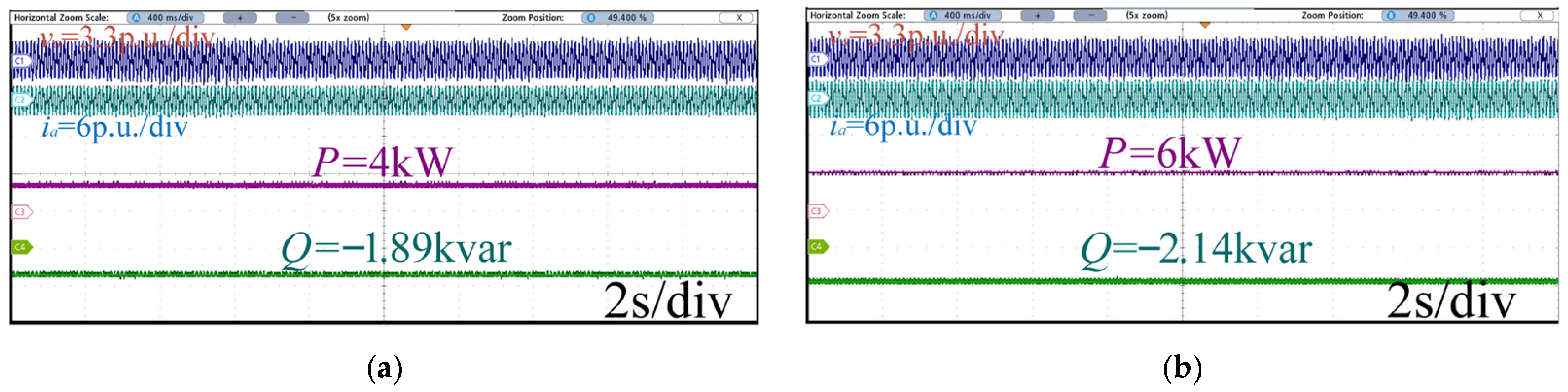
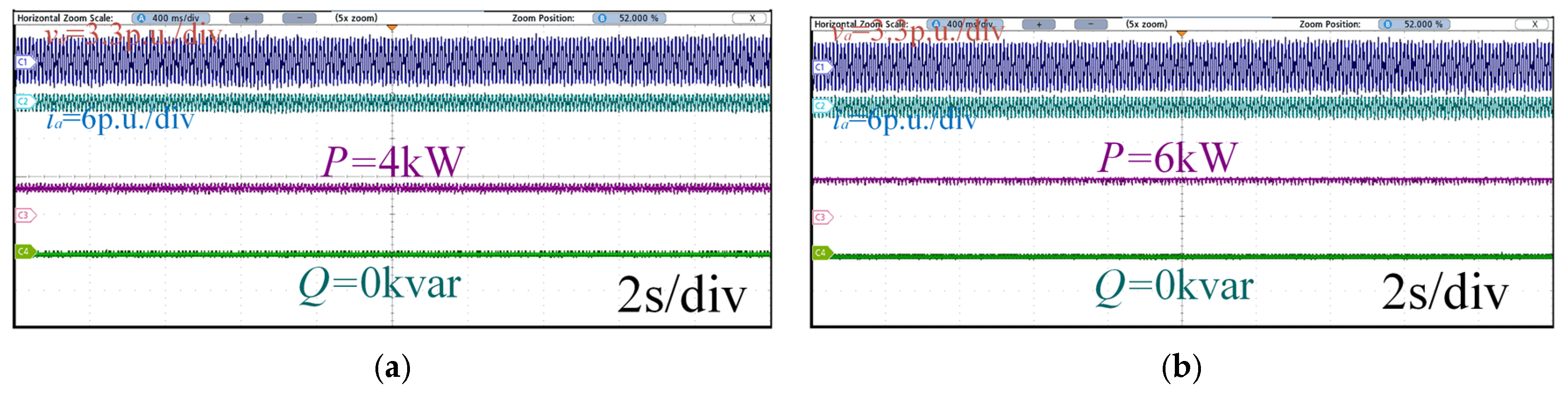
The experimental waveforms of the GFM converter under different methods when only outputting active power are shown in Figure 14 and Figure 15. In the case of no power decoupling method (only VSG control), the Q reaches −1.89 kvar when the references are set as Pn = 4 kW and Qn = 0 var, in Figure 14a, which is consistent with the theoretical results. Moreover, when the references are set as Pn = 6 kW and Qn = 0 var in the GFM converter system, it can be observed that the reactive power Q is almost 2.14 kvar in Figure 14b. This indicates severe steady-state power coupling. In contrast, the proposed method shows a satisfactory power decoupling performance. With the references configured as Pn = 4 kW and Qn = 0 var, the reactive power Q is approximately 0 var in Figure 15a. Moreover, when the GFM converter operates with Pn = 6 kW and Qn = 0 var, the reactive power Q is almost 0 var, as illustrated in Figure 15b. The proposed method can achieve power decoupling in a steady state, which is consistent with the simulation results.
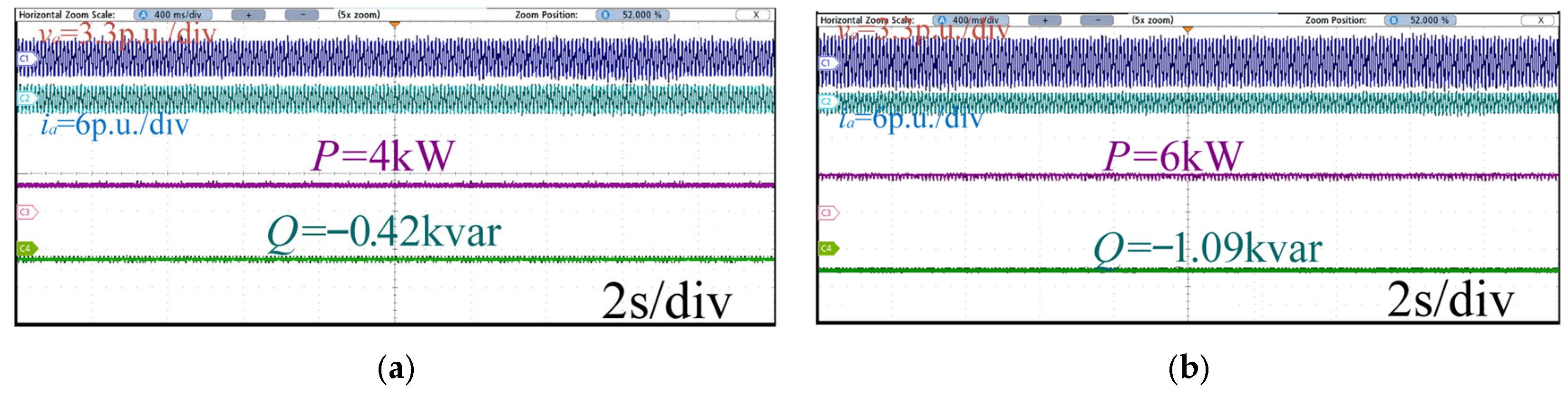
Furthermore, the experimental waveforms of the GFM converter under the optimal virtual inductor method [27] with different power references are shown in Figure 16. With the references configured as Pn = 4 kW and Qn = 0 var (Figure 16a), the reactive power Q is reduced to −0.42 kvar compared with Figure 14a. Moreover, when the GFM converter operates with Pn = 6 kW and Qn = 0 var (Figure 16b), the reactive power Q is reduced to −1.09 kvar compared with Figure 14b. The optimal virtual inductor method could suppress power coupling, but cannot achieve complete power decoupling.

4.2.2. Dynamic Performance of Power Decoupling

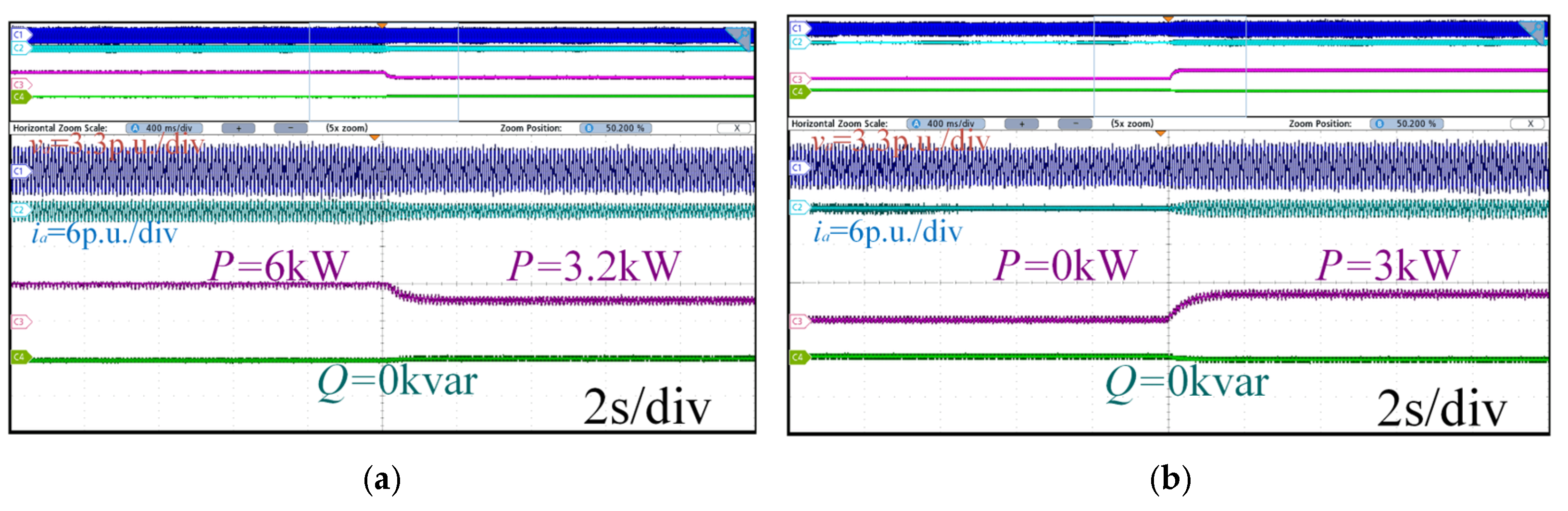
The dynamic power waveforms of the GFM converter under different methods are presented in Figure 17. When Pn steps down from 6 kW to 3.2 kW, the reactive power Q remains at 0 var in Figure 17a. Regardless of whether the Pn steps down from 6 kW to 3.2 kW or up from 0 W to 3 kW, the fluctuation of output reactive power is less than 10 var, and the output reactive power remains at 0 var. Thus, with the proposed method implemented, the reactive power fluctuations can be considered negligible, indicating a satisfactory dynamic power decoupling capability.
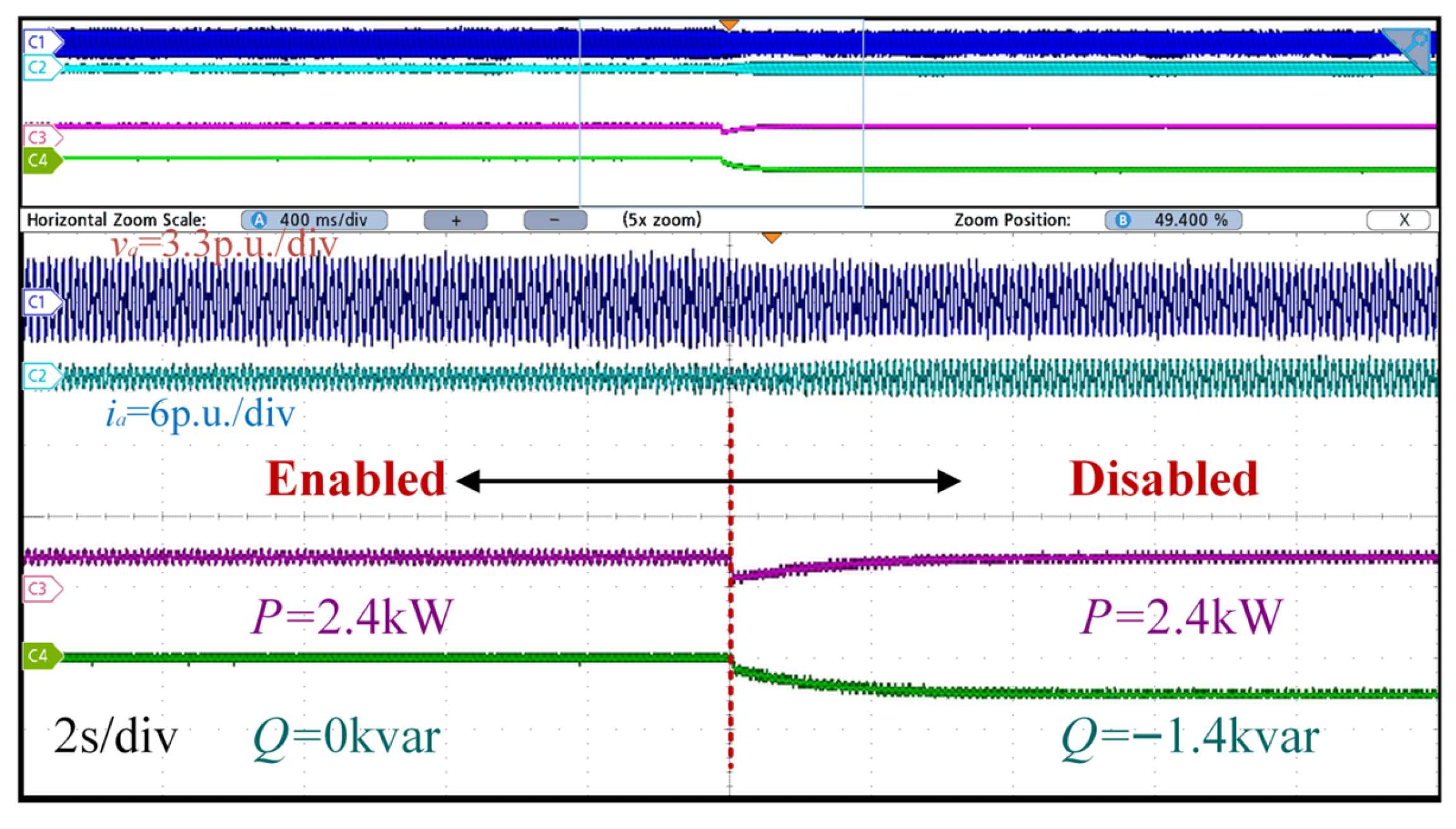
To further validate the efficacy of the proposed method, the experimental power waveforms are shown in Figure 18 when the proposed method is suddenly disabled. It can be observed that when the method is applied, even with the active power reference Pn = 2.4 kW, the reactive power Q remains 0 var, following the reference value (Qn = 0 var), demonstrating a strong decoupling performance between active and reactive powers. However, when the proposed method is disabled, the reactive power instantaneously increases to −1.4 kvar, resulting in inaccurate power control for the GFM converter. It proves from the opposite side that the proposed method has a significant decoupling effect on active and reactive power, which is great for improving the power control ability under complex power grids.

4.2.3. Pre-Synchronization Experiments for the Proposed Method

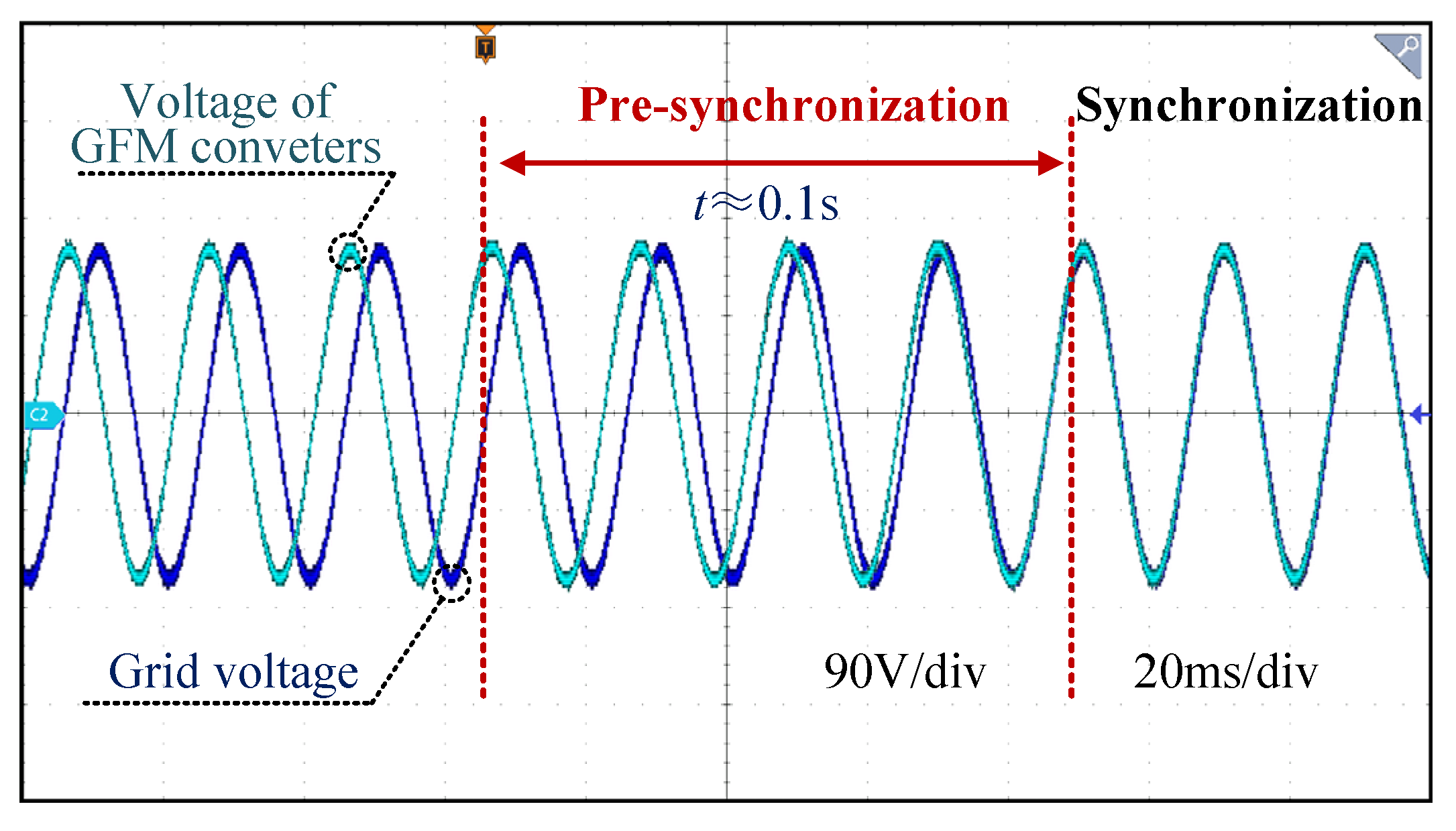
The experimental waveforms of the converter voltage tracking the grid voltage are shown in Figure 19. The GFM converter operates in the islanded mode, and the voltage phase of the GFM converters differs from that of the grid voltage in the beginning. When the improved pre-synchronization control is implemented, the phase difference between the voltage of the GFM converters and the grid voltage is gradually reduced. It takes 0.1 s for the voltage of the GFM converters to coincide with the grid voltage, indicating that the GFM converter voltage has achieved synchronization with the grid voltage, ensuring seamless switching.

5. Conclusions

This paper proposes an adaptive power decoupling control method with pre-synchronization for GFM converters, which reshapes the power control loop without line impedance parameters. The proposed method effectively mitigates power coupling-induced varying line impedance (R/X ratios), and it improves power control accuracy. By constructing power coupling coefficients, the dominant influence of active power on reactive power and the nonlinear characteristics of power coupling are explicitly revealed. An SM control-based power decoupling strategy dynamically modifies the voltage reference, achieving effective decoupling of active and reactive power. Furthermore, the reactive power control is refined to ensure a precise tracking performance under the complex grid conditions. Additionally, the SM control-based pre-synchronization strategy operates without PLLs, enabling the GFM converter to switch to the grid-connected mode from the islanded mode seamlessly. The experimental results verified the validity and feasibility of the proposed method.

Author Contributions

Conceptualization, Q.R., Z.X., and T.L.; methodology, Q.R., R.P., and T.L.; software, Q.R., Y.Z., and T.L.; validation, Q.R. and T.L.; formal analysis, Q.R. and T.L.; investigation, Q.R., C.S., and T.L.; resources, Q.R., and T.L.; data curation, Q.R. and T.L.; writing—original draft preparation, Q.R. and T.L.; writing—review and editing, Q.R. and T.L.; supervision, Q.R. and T.L.; project administration, Q.R. and T.L.; funding acquisition, Q.R. and T.L. All authors have read and agreed to the published version of the manuscript.

Funding

This research was funded by the National Science and Technology Major Project on Smart Grid, grant No. 2025ZD0804200, National Natural Science Foundation of China, grant No. 62403278, and National Natural Science Foundation of Shandong Province, grant No. ZR2024QE180. The authors gratefully acknowledge this support.

Data Availability Statement

The original contributions presented in this study are included in the article, and further inquiries can be directed to the corresponding author.

Conflicts of Interest

Authors Qicai Ren, Zefeng Xu, Rongcai Pan, Yanxu Zhang and Chao Sheng were employed by the company Guangdong Power Grid Co., Ltd. The remaining authors declare that the research was conducted in the absence of any commercial or financial relationships that could be construed as a potential conflict of interest.

Abbreviations

The following abbreviations are used in this manuscript:
GFMGrid-forming
PLLPhase-locked loop
PIProportional integral
SMSliding mode
VSGVirtual synchronous generator

References

  1. Strielkowski, W.; Civín, L.; Tarkhanova, E.; Tvaronavičienė, M.; Petrenko, Y. Renewable Energy in the Sustainable Development of Electrical Power Sector: A Review. Energies 2021, 14, 8240. [Google Scholar] [CrossRef]
  2. Kafetzis, A.; Kardaras, G.; Bampaou, M.; Panopoulos, K.D.; Sarmas, E.; Marinakis, V.; Tsekouras, A. Deployment of Modular Renewable Energy Sources and Energy Storage Schemes in a Renewable Energy Valley. Energies 2025, 18, 5837. [Google Scholar] [CrossRef]
  3. Fang, Y.; Hu, P.; Zhu, N.; Minfu, A.; Jiang, D. Sizing method of a novel hybrid energy storage considering adaptive inertia control. Sustain. Energy Technol. Assess. 2024, 61, 103602. [Google Scholar] [CrossRef]
  4. Xin, H.; Liu, C.; Chen, X.; Wang, Y.; Prieto-Araujo, E.; Huang, L. How Many Grid-Forming Converters Do We Need? A Perspective from Small Signal Stability and Power Grid Strength. IEEE Trans. Power Syst. 2025, 40, 623–635. [Google Scholar] [CrossRef]
  5. Shi, K.; Wang, Y.; Sun, Y.; Xu, P.; Gao, F. Frequency-Coupled Impedance Modeling of Virtual Synchronous Generators. IEEE Trans. Power Syst. 2021, 36, 3692–3700. [Google Scholar] [CrossRef]
  6. Zhong, Q.-C.; Konstantopoulos, G.C.; Ren, B.; Krstic, M. Improved synchronverters with bounded frequency and voltage for smart grid integration. IEEE Trans. Smart Grid 2018, 9, 786–796. [Google Scholar] [CrossRef]
  7. He, K.; Tang, Y.; Hu, M.; Guo, L. Sub-synchronous oscillation suppression strategy for virtual synchronous generators based on dual-loop sliding mode control. Sustain. Energy Technol. Assess. 2024, 65, 103794. [Google Scholar] [CrossRef]
  8. Strunz, K.; Almunem, K.; Wulkow, C.; Kuschke, M.; Valescudero, M.; Guillaud, X. Enabling 100% renewable power systems through power electronic grid-forming converter and control: System integration for security stability, and application to Europe. Proc. IEEE 2023, 111, 891–915. [Google Scholar] [CrossRef]
  9. Li, Y.; Gu, Y.; Green, T.C. Revisiting grid-forming and grid following inverters: A duality theory. IEEE Trans. Power Syst. 2022, 37, 4541–4554. [Google Scholar] [CrossRef]
  10. Zhong, Q.-C.; Weiss, G. Synchronverters: Inverters that mimic synchronous generators. IEEE Trans. Ind. Electron. 2010, 58, 1259–1267. [Google Scholar] [CrossRef]
  11. Liu, H.; Zhang, W.; Sun, B.; Loh, P.C.; Wang, W.; Xu, D.; Blaabjerg, F. Seamless transfer scheme with unified control core for paralleled systems. IEEE Trans. Power Electron. 2019, 34, 6286–6298. [Google Scholar] [CrossRef]
  12. Vukojevic, A.; Lukic, S. Microgrid protection and control schemes for seamless transition to island and grid synchronization. IEEE Trans. Smart Grid 2020, 11, 2845–2855. [Google Scholar] [CrossRef]
  13. Dong, N.; Li, M.; Chang, X.; Zhang, W.; Yang, H.; Zhao, R. Robust Power Decoupling Based on Feed-forward Decoupling and Extended State Observers for Virtual Synchronous Generator in Weak Grid. IEEE J. Emerg. Sel. Top. Power Electron. 2023, 11, 576–587. [Google Scholar] [CrossRef]
  14. Hao, X.; Zhang, Y.; Dang, H.; Wang, X.; Zhang, C. A virtual resistance-based pre-synchronization control for grid-forming converters with seamless transfer capability. Sustain. Energy Technol. Assess. 2025, 77, 10435. [Google Scholar] [CrossRef]
  15. Meng, X.; Liu, Z.; Zheng, H.; Liu, J. A Universal Controller Under Different Operating States for Parallel Inverters with Seamless Transfer Capability. IEEE Trans. Power Electron. 2020, 35, 9794–9812. [Google Scholar] [CrossRef]
  16. Zhu, Z.; Huang, S. Research on seamless switching control strategy of microgrid power converter system based on VSG. Control Eng. China 2021, 28, 488–494. [Google Scholar] [CrossRef]
  17. Shi, K.; Song, W.; Ge, H.; Xu, P.; Yang, Y.; Blaabjerg, F. Transient analysis of microgrids with parallel synchronous generators and virtual synchronous generators. IEEE Trans. Energy Convers. 2020, 35, 95–105. [Google Scholar] [CrossRef]
  18. Yang, L.; Wang, C.; Lv, Z.; Liu, L.; Liu, H.; Zeng, Z. The method of pre-synchronized grid-connection of synchronverter. Power Syst. Technol. 2014, 38, 3103–3108. [Google Scholar] [CrossRef]
  19. Lan, Z.; Diao, W.; Zeng, J.; He, D.; Tu, C.; Jiang, F. Pre-synchronization control strategy of virtual synchronous generator in islanded microgrid with heterogeneous distributed generators. Autom. Electr. Power Syst. 2022, 46, 154–161. [Google Scholar] [CrossRef]
  20. Huang, Z.; Liu, Z.; Shen, G.; Li, K.; Song, Y.; Su, B. A Virtual Synchronous Generator-Based Control Strategy and Pre-Synchronization Method for a Four-Leg Inverter under Unbalanced Loads. Symmetry 2024, 16, 1116. [Google Scholar] [CrossRef]
  21. Yuan, Y.; Ma, J.; Wang, S.; Wang, P.; Liu, T. Transient Stability Analysis of Grid-Forming Converters During Presynchronization Process in Islanded Mode. IEEE Trans. Power Electron. 2024, 39, 11007–11019. [Google Scholar] [CrossRef]
  22. Zhou, L.; Zheng, G.; Liao, B. A novel control strategy of distributed generation in microgrid. Electr. Power Constr. 2014, 35, 38–43. [Google Scholar] [CrossRef]
  23. Brabandere, K.D.; Bolsens, B.; Woyte, A.; Driesen, J.; Belmans, R. A Voltage and Frequency Droop Control Method for Parallel Inverters. IEEE Trans. Power Electron. 2007, 22, 1107–1115. [Google Scholar] [CrossRef]
  24. Li, Y.; Li, Y. Power Management of Inverter Interfaced Autonomous Microgrid Based on Virtual Frequency-Voltage Frame. IEEE Trans. Smart Grid 2011, 2, 30–40. [Google Scholar] [CrossRef]
  25. Li, B.; Zhou, L.; Yu, X.; Zheng, C.; Liu, J. Improved power decoupling control strategy based on virtual synchronous generator. IET Power Electron. 2017, 10, 462–470. [Google Scholar] [CrossRef]
  26. Tian, Y.; Xu, X.; Wang, Y.; Li, Z.; Zhang, Z.; Gao, Y. Full-state feedback power decoupling control for grid forming converter with improved stability and inertia response. IEEE Trans. Power Electron. 2025, 40, 2930–2942. [Google Scholar] [CrossRef]
  27. Wen, T.; Zhu, D.; Zou, X.; Jiang, B.; Peng, L.; Kang, Y. Power coupling mechanism analysis and improved decoupling control for virtual synchronous generator. IEEE Trans. Power Electron. 2021, 36, 3028–3041. [Google Scholar] [CrossRef]
  28. Huang, M.; Li, H. Disturbance rejection control of grid-forming inverter for line impedance parameter perturbation in weak power grid. Electronics 2024, 13, 1926. [Google Scholar] [CrossRef]
  29. Lee, H.-S.; Choi, Y.-J. Optimal virtual impedance-based power decoupling control strategy for grid-forming inverter. In Proceedings of the IECON 2024—50th Annual Conference of the IEEE Industrial Electronics Society, Chicago, IL, USA, 3–6 November 2024; pp. 1–6. [Google Scholar]
  30. Long, B.; Zhu, S.; Rodriguez, J.; Guerrero, J.M.; Chong, K.T. Enhancement of Power Decoupling for Virtual Synchronous Generator: A virtual inductor and virtual capacitor approach. IEEE Trans. Ind. Electron. 2023, 70, 6830–6843. [Google Scholar] [CrossRef]
Figure 1. The circuit of the GFM converter.
Energies 19 00784 g001
Figure 2. The VSG grid-connected simplified circuit model.
Energies 19 00784 g002
Figure 3. Equivalent circuit diagram of a grid-forming converter connected to the grid.
Energies 19 00784 g003
Figure 4. Small-signal model of GFM converters based on VSG.
Energies 19 00784 g004
Figure 5. Variation in coupling coefficient with various line impedance angles: (a) ξ1 with various line impedance angles; (b) ξ2 with various line impedance angles.
Energies 19 00784 g005
Figure 6. Proposed power decoupling method diagram.
Energies 19 00784 g006
Figure 7. The power decoupling effects of the proposed method.
Energies 19 00784 g007
Figure 8. The control block of the improved pre-synchronization.
Energies 19 00784 g008
Figure 9. Overall control block of the proposed method.
Energies 19 00784 g009
Figure 10. Simulation waveforms of the pre-synchronization.
Energies 19 00784 g010
Figure 11. Simulation power waveforms of two methods: (a) VSG method (without power decoupling); (b) proposed adaptive power decoupling method.
Energies 19 00784 g011
Figure 12. Simulation power waveforms with disturbances: (a) VSG method (without power decoupling); (b) proposed adaptive power decoupling method.
Energies 19 00784 g012
Figure 13. Configuration of the experimental platform.
Energies 19 00784 g013
Figure 14. Experimental results of the VSG method (without power decoupling): (a) Pn = 4 kW, Qn = 0 var; (b) Pn = 6 kW, Qn = 0 var.
Energies 19 00784 g014
Figure 15. Experimental results of the proposed method: (a) Pn = 4 kW, Qn = 0 var; (b) Pn = 6 kW, Qn = 0 var.
Energies 19 00784 g015
Figure 16. Experimental results of the virtual inductor method: (a) Pn = 4 kW, Qn = 0 var; (b) Pn = 6 kW, Qn = 0 var.
Energies 19 00784 g016
Figure 17. Dynamic results of the proposed method with Qn = 0 var: (a) Pn decreases from 6 kW to 3.2 kW; (b) Pn increases from 0 W to 1 kW.
Energies 19 00784 g017
Figure 18. Experimental results of the two methods (Pn = 2.4 kW, Qn = 0 var).
Energies 19 00784 g018
Figure 19. Experimental results of the pre-synchronization.
Energies 19 00784 g019
Table 1. The comparison of the power decoupling method.
MethodLine Impedance InformationPower Reference
Information
Power Angle
Information
Virtual inductor [27]NeedDo not needDo not need
Virtual power [23]Need rate of R/XDo not needDo not need
Feedback compensation [25]Do not needNeedNeed
Proposed methodDo not needDo not needDo not need
Table 2. Main parameters of the GFM converter.
ParameterValue
Grid voltage vga, vgb, vgc110 V (1 p.u.)
DC-link voltage400 V (1 p.u.)
Rated active power6 kW (1 p.u.)
Rated reactive power6 kvar (1 p.u.)
Line resistance Rg3 Ω
Line inductance Lg5 mH
Filter inductance L3 mH
Filter capacitance C12 μF
Sampling time Ts50 μs
Disclaimer/Publisher’s Note: The statements, opinions and data contained in all publications are solely those of the individual author(s) and contributor(s) and not of MDPI and/or the editor(s). MDPI and/or the editor(s) disclaim responsibility for any injury to people or property resulting from any ideas, methods, instructions or products referred to in the content.