Article

Underground Coal Gasification Induced Multi-Physical Field Evolution and Overlying Strata Fracture Propagation: A Case Study Targeting Deep Steeply Inclined Coal Seams


1
Xinjiang Key Laboratory of Continental Dynamics and Mineralization Prediction of the Central Asian Orogenic Belt, Xinjiang University, Urumqi 830047, China
2
Geological Research Institute of Xinjiang Uygur Autonomous Region, Urumqi 830091, China
3
Xinjiang Research Institute of Huairou Laboratory, Urumqi 830011, China
*
Authors to whom correspondence should be addressed.
Energies 2026, 19(2), 559; https://doi.org/10.3390/en19020559
Submission received: 21 November 2025 / Revised: 13 December 2025 / Accepted: 20 January 2026 / Published: 22 January 2026
(This article belongs to the Section B2: Clean Energy)

Abstract

Underground coal gasification (UCG) is a controlled combustion process of in situ coal that produces combustible gases through thermal and chemical reactions. In order to investigate the UCG induced multi-physical field evolution and overlying strata fracture propagation of deep steeply inclined coal seam (SICS), which play a vital role in safety and sustainable UCG project, this study established a finite element model based on the actual geological conditions of SICS and the controlled retracting injection point (CRIP) technology. The results are listed as follows: (1) the temperature field influence ranges of the shallow and deep parts of SICS expanded from 15.56 m to 17.78 m and from 26.67 m to 28.89 m, respectively, when the burnout cavity length increased from 100 m to 400 m along the dip direction; (2) the floor mudstone exhibited uplift displacement as a result of thermal expansion, while the roof and overlying strata showed stepwise-increasing subsidence displacement over time, which was caused by stress concentration and fracture propagation, reaching a maximum subsidence of 3.29 m when gasification ended; (3) overlying strata rock damages occurred with induced fractures developing and propagating during UCG. These overlying strata fractures can reach a maximum height of 204.44 m that may result in groundwater influx and gasification failure; (4) considering the significant asymmetry in the evolution of multi-physical fields of SICS, it is suggested that the dip-direction length of a single UCG channel be limited to 200 m. The conclusions of this study can provide theoretical guidance and technical support for the design of UCG of SICS.

1. Introduction

Globally, coal resources are an indispensable energy source and will continue to be essential for a considerable period of time [1,2,3,4]. Traditional coal-mining techniques have struggled to develop deep coal resources [5]. New coal fluidization mining technologies are required to effectively extract coal-based oil and gas resources from deep coal seams [6], and to improve oil and gas supply situation [7,8]. Underground coal gasification (UCG) is a clean, safe, and efficient new technology that is ideal for coal resource development [9,10,11]. Its principle involves the controlled combustion of coal seams in situ to produce combustible gas. UCG integrates well construction, gasification, and gas extraction into a single integrated process [12,13,14], making it suitable for extracting hard-to-reach coal resources, such as deep-seated and steeply inclined deposits [15,16,17,18,19]. UCG is a key choice for green, low-carbon, high-quality development and transformation [20,21,22,23].
UCG technology holds great promise, but significant challenges remain in practical application regarding the continuous operation of gasifiers and the stability of overlying rock structures during the gasification process [24,25]. The gasification center temperature during the UCG process can reach between 800 °C and 1200 °C [26,27,28]. Prolonged exposure to high temperatures can degrade the physicochemical properties of the overlying strata, causing varying degrees of deformation, damage, and fragmentation, which may lead to surface subsidence and trigger geological hazards [29,30,31]. Difficult-to-mine coal seams (such as deep coal seams, steeply inclined coal seams, and thin coal seams) are characterized by complex geological conditions [32,33]. The cavities formed after gasification redistribute overlying rock stresses [34], while high temperatures cause thermal damage to the rock, reducing its strength [35,36]. When the induced overlying strata fractures begin to develop and expand [37,38,39], potentially connecting aquifers and causing groundwater inflow, this may compromise the sustained safe operation of UCG. Therefore, it is essential to investigate the expansion patterns of the induced overlying strata fractures and the multi-physics evolution characteristics during UCG implementation, which are significant for the stable operation of gasification furnaces and the design of practical UCG projects [40,41].
In recent years, numerous scholars have conducted extensive numerical simulation studies on UCG by utilizing finite element simulation analysis software to address overlying strata stability and the evolution characteristics of multi-physical fields during UCG process. Cui et al. established a discrete multi-physics coupling mathematical model to investigate cavity formation and temperature changes during the UCG process. The results indicated that cavity growth varied with the gas flow rate [42]. Zhao et al. used COMSOL software to establish a geological model for investigating the temperature field distribution in the UCG process. The results demonstrated that the temperature field in the roof and floor strata continuously expanded because of the persistent heat transfer from the combustion products [43]. Duan et al. established a thermomechanical coupling fracturing model for numerical simulation. The results indicated that fractures formed in the highest temperature zone and propagated toward the lower temperature zones as temperature increased [44]. Zhang et al. used COMSOL software to establish a multi-field coupled two-dimensional (2D) numerical model, investigating the relationship between tensile-shear damage at the gasification center and both gasification temperature and coal-rock fracture coupling. The results indicated that the gasification center of the coal rock underwent tensile expansion as a result of thermal stress and pore pressure, resulting in tensile damage [45]. Wang et al. employed the controlled retraction injection point technique and used ABAQUS finite element software to simulate the controlled combustion reaction in the coal seam and cavity formation following gasification during UCG. The study analyzed the evolution patterns of the temperature and displacement fields in the number 12 coal seam after gasification, The results indicated that the temperature conduction range of coal and rock gradually expands at the gasification point moving with time [46]. Yao et al. also used ABAQUS (v2017) software to establish a large-scale, long-channel UCG numerical model, investigating the development and propagation patterns of fractures under multi-field coupling effects at different burn-cavity distances in the gasification channel. The simulation results demonstrated that longer burn-cavity distances in the gasification channel led to a greater diffusion range of the temperature field, with the fracture propagation height reaching a maximum of 270 m [47].
In summary, although substantial research has been conducted on multi-field coupling in UCG, the mechanisms of asymmetric overburden failure induced by the CRIP long-channel process under the specific geological conditions of deep steeply inclined coal seams (SICS) remain insufficiently explored. Compared with existing studies, the improvements of this work lie in: (1) establishing a two-dimensional coupled model that more closely aligns with the geological structure of SICS and the characteristics of the CRIP process, with a focus on the asymmetric evolution along the dip direction; and (2) systematically considering the controlling role of pre-existing natural fracture networks on the failure process, and directly linking the multi-field evolution patterns to the optimization of engineering parameters. Based on geological data from SICS in the Fukang mining area of the Junggar Basin, Xinjiang, China, this study established a UCG finite element model for SICS using the controlled retracting injection point (CRIP) technology, to investigate the multi-field coupling evolution patterns during UCG of SICS and the development characteristics of induced fractures in overlying strata. The findings from this study provide theoretical guidance for the design of practical UCG of SICS engineering parameters and are essential to ensure the safe and stable operation of UCG gasifiers.

2. Geological Conditions of SICS

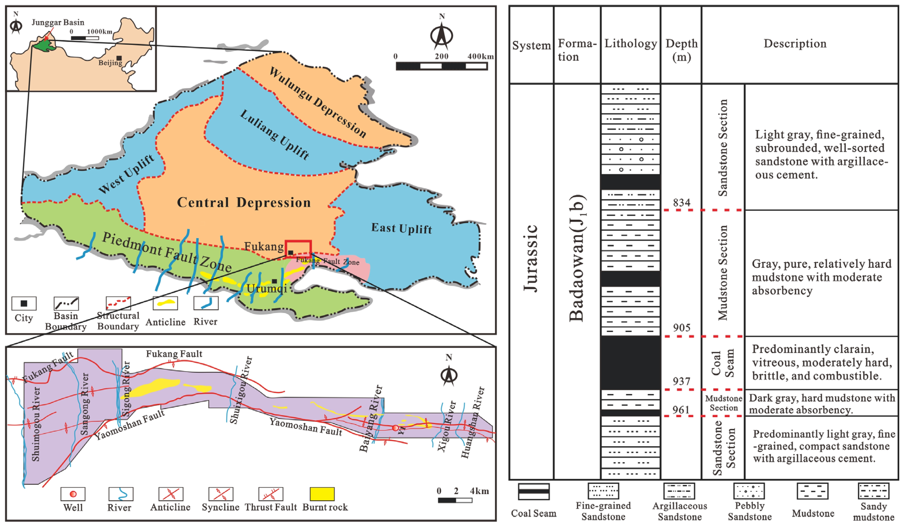
This study focuses on SICS in the Fukang mining area of northwestern China, which is situated within the North Tianshan Fold Belt, and features a structural configuration of a south-dipping monocline. The strike direction is approximately east–west, with a stratigraphic dip angle ranging from 45° to 53°. The coal-bearing strata primarily consist of the Lower Jurassic Badaowan Formation, with the main target coal seam being the No. 42 coal seam. This seam features a simple structure and a thickness of 32 m.

3. Numerical Model

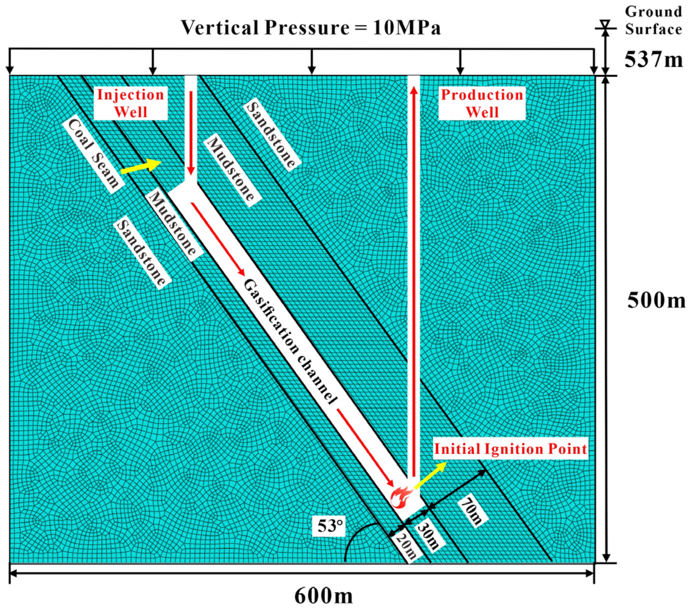
On the basis of the geological conditions of the Y1 well area in the Fukang mining area, where the actual UCG operations are conducted (Figure 1), this study established a two-dimensional numerical model with the following parameters: 30 m of coal seam thickness, 53° of coal seam dip angle, 70 m of roof mudstone thickness, 20 m of floor mudstone thickness, 400 m of designed gasification channel length, and 887 m of burial depth at the center of the gasification channel (Figure 2).
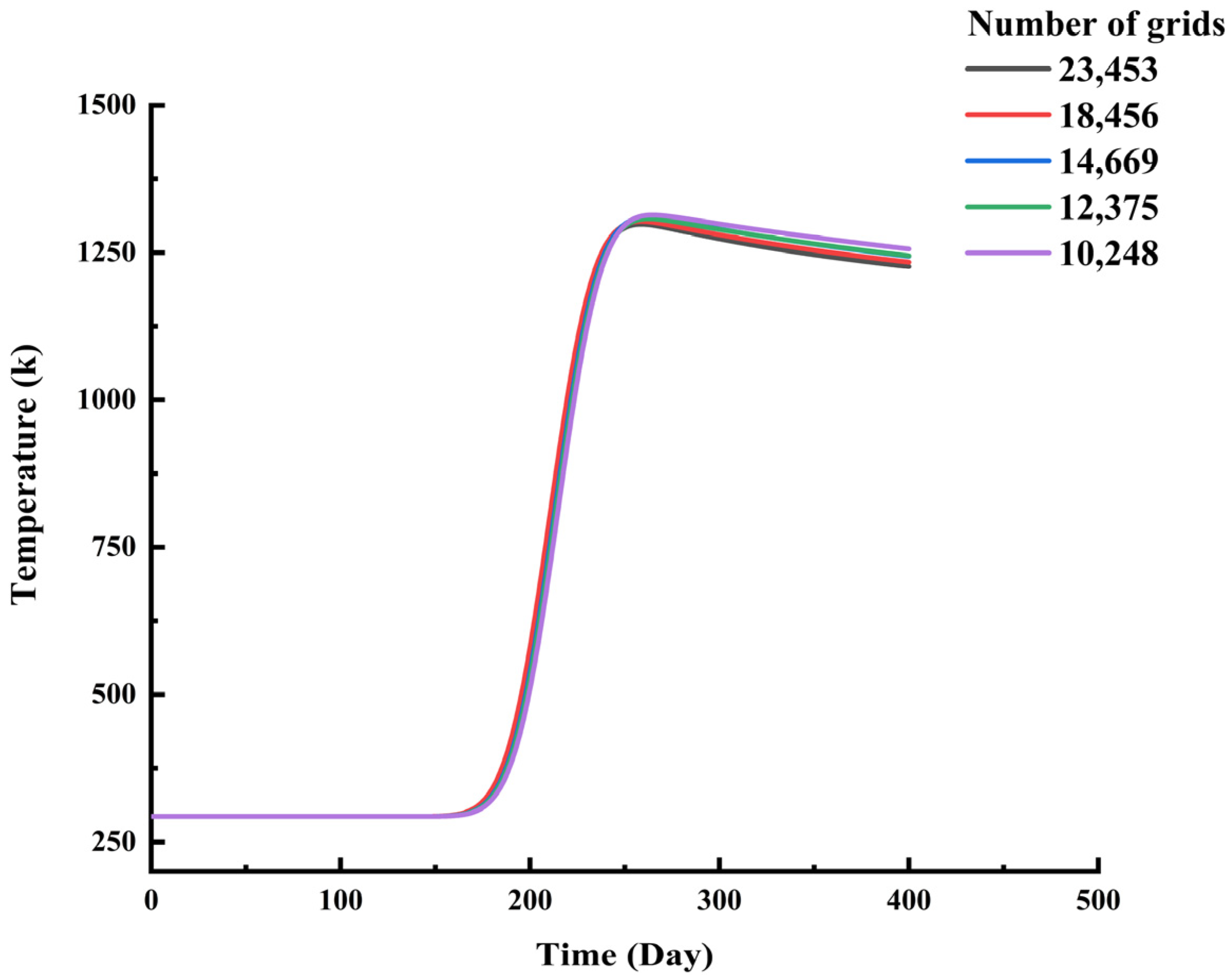
A grid independence study confirmed that the temperature calculation results were insensitive to the number of mesh elements (Figure 3), and to evaluate the stability and computational efficiency of the numerical model, this study also monitored the convergence behavior of the solver. In particular, key convergence indicators from result files such as the STA and MSG files show that during each increment, the number of attempts was predominantly 1 and never exceeded 10, the number of severe discontinuity iterations remained consistently at 0, and the total equilibrium iterations per increment did not exceed 6. These data indicate that the model achieved equilibrium rapidly during the computation process, with no convergence difficulties arising from computational instability. This demonstrates the rationality of the current mesh design, material parameters, and boundary condition settings, thereby ensuring the reliability of the computational results. To ensure computational accuracy and efficiency, we selected a mesh size of 5 m (totaling 14,669 elements). The fundamental model parameters and the physical and mechanical properties of various rock strata are presented in Table 1 and Table 2. We applied a vertical pressure of 10 MPa to the top of the overlying strata to simulate in situ formation pressure, whereas all other boundaries were assigned fixed constraints. The initial ambient temperature of the model was set at 20 °C, and the gasification face was advanced at a constant rate of 1 m/d. It should be noted that the lateral stress ratio and boundary conditions exert a certain influence on the damage zone morphology and fracture connectivity height. Under conditions of a higher lateral stress ratio, enhanced horizontal compressive stress provides lateral confinement to the roof and overlying strata, thereby delaying the opening and upward propagation of fractures. This tends to reduce the height and extent of the damage zone to some extent. Conversely, a lower lateral stress ratio weakens the surrounding rock’s ability to confine deformation, making it easier for upward-connected tensile fracture networks to develop, which can lead to an increase in the height of the water-conducting fracture zone.
The Gaussian-distributed moving heat source model adopted in this study is a commonly used method for simulating the progressive combustion face in the CRIP process. The heat source parameters directly determine the peak and extent of the temperature field. The variations in the temperature field induced thermal strain through the thermal expansion effect, which was subsequently converted into thermal stress under constrained conditions. Simultaneously, high-temperature environments generally contributed to the degradation of the rock’s yield strength. Damage evolution was jointly influenced by the stress and temperature fields, with the initiation and propagation of fractures being the result of coupled thermomechanical effects. Once the damage occurred, the stiffness of the rock material underwent progressive degradation, thereby triggering a redistribution of the stress field and inducing the development of a local displacement field.
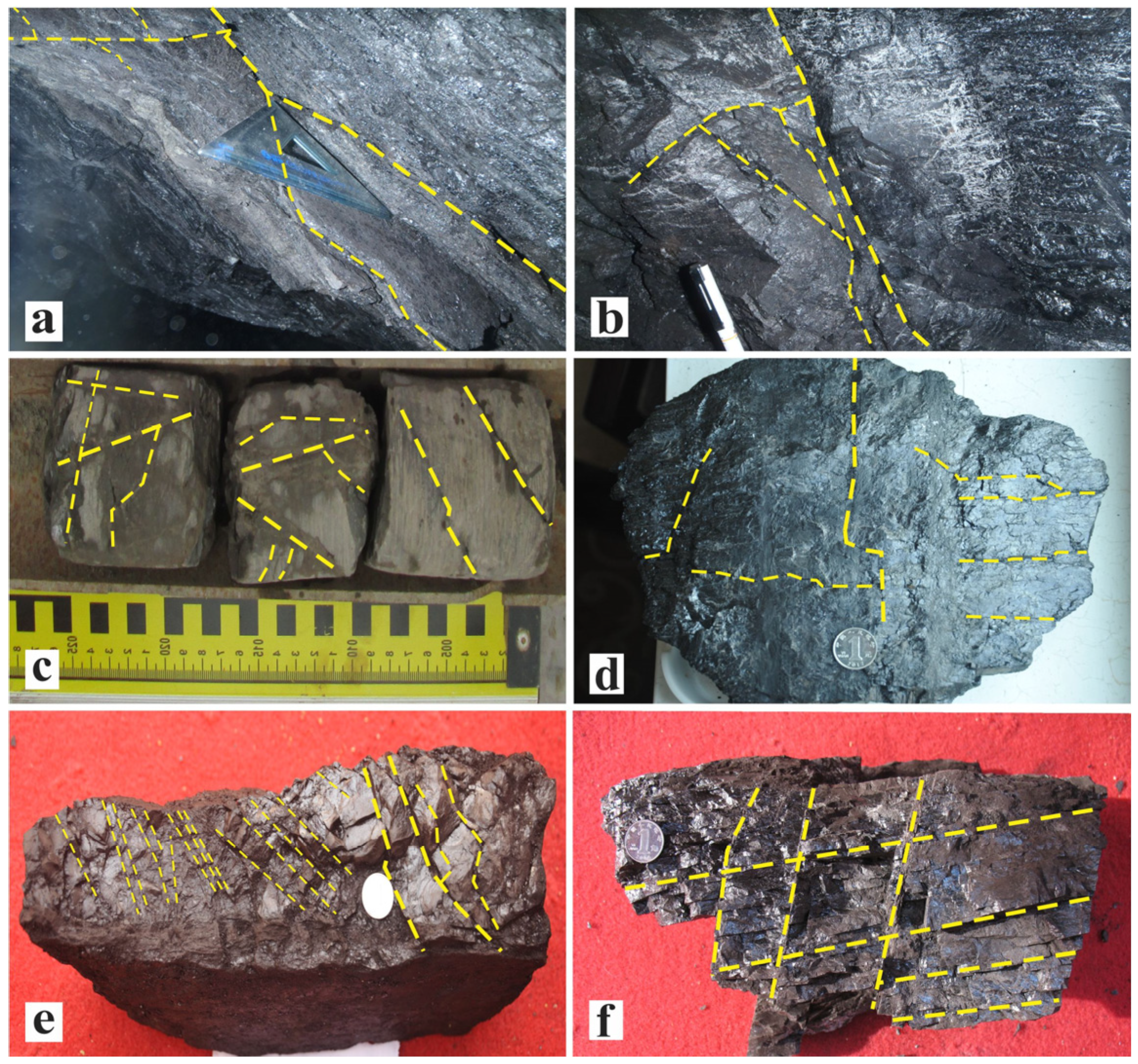
The coal seams in the Fukang mining area have undergone prolonged geological activities and are structurally controlled by a syncline, which has resulted in complex geological conditions and a steep dip angle. Field investigations confirmed widespread surface fractures throughout the study area, with larger fractures spaced approximately 50~70 m apart, validating that the coal rock, subjected to intense compression and deformation, exhibited well-developed natural fractures. Under mining-induced disturbances, these fractures propagated and formed an interconnected fracture network (Figure 4).
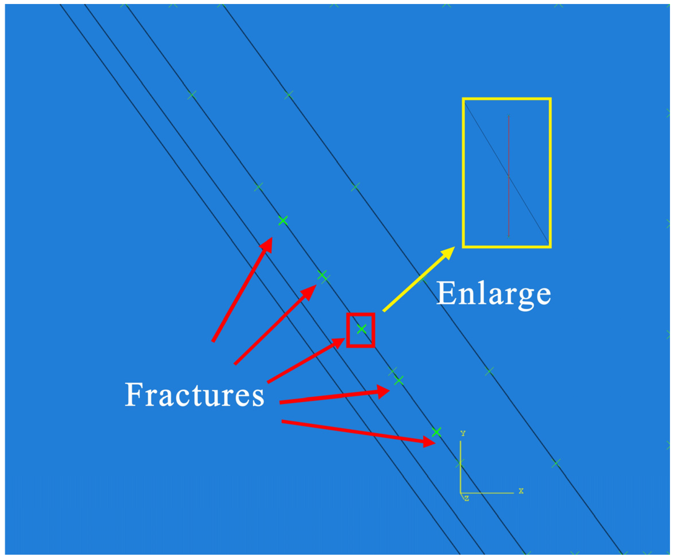
In this study, we simulated the natural fractures present in the coal seam by incorporating a pre-determined number of pre-embedded fractures (Figure 5) and investigated the propagation characteristics of the induced fractures in the overlying strata during UCG of SICS.

4. Governing Equations

4.1. Heat Distribution

Thermal energy released during underground coal gasification is spatially heterogeneous due to localized combustion and heat transfer processes within the coal–rock system. In this study, we defined the nonuniform heat distribution as a heat flux function of location, time, temperature, and the number of integration points through the DFLUX subroutine in ABAQUS:
Φ = q ( r ) d x d y
where Φ denotes the heat input applied to the model, J; and q(r) represents the local heat flux density, J/m2.
During coal seam combustion, continuous heat generation led to a nonuniform distribution of the thermal flux in the gasification process. This nonuniformity was characterized by a higher heat flux density closer to the central heat source, which resulted in increased thermal flux in the surrounding rock. On the basis of the Gaussian surface heat source model, the heat flux density is expressed as follows:
q ( r ) = 3 Q π r 0 2 exp 3 r 2 r 0 2
where Q is the total heat generated during UCG process, J; r0 is the effective radius of the heat source, m; and r denotes the distance from a given point to the center of the surface heat source, m.

4.2. Thermoelastic Constitutive Equation

The mechanical response of the surrounding rock under thermal loading is described using a linear thermoelastic constitutive relationship. The rock material is assumed to behave elastically within the temperature range considered, and the numerical model is treated as a two-dimensional plane strain problem. Under these assumptions, the coupled stress–strain–temperature relationship can be written as:
σ i j = 2 G ε i j + λ 1 ( ε x x + ε y y ) + 3 α t K Δ T
where G is the shear modulus, Pa; K is the bulk modulus, Pa; εij is the stress tensor; εxx and εyy are normal strain components in the x and y directions, respectively; λ1 is Lame’s constant, Pa; αt is the coefficient of thermal expansion, k−1; and ΔT represents the temperature increment, K.

4.3. Formation of the Gasified Cavity

After gasification completion, the coal seam formed a gasification cavity. Using the ABAQUS software, we simultaneously invoked the GETVRM and USDFLD subroutines. We introduced the live/dead element rule and defined STATEV to execute element retention and deletion. If the cell temperature was less than 1273.15 K, then STATEV was 1 and the element remains active; conversely, the temperature was greater than 1273.15 K [28], then STATEV was 0 and the cell was deleted, forming a gasified cavity:
STATEV = 1 ,   units   retain STATEV = 0 ,   units   delete

4.4. Initiation Criterion for Damage

Rock damage initiation is evaluated using a maximum principal stress criterion. Damage is assumed to initiate when the maximum principal stress within the rock exceeds its critical allowable value. A crack was initiated or an existing crack propagated after an equilibrium increment when the fracture criterion f reached 1.0 within a specified tolerance, defined as follows: 1.0 ≤ f ≤ 1.0 + ftol. The tolerance ftol could be user-defined, with a system default value of 0.05. The fracture criterion f can be expressed as follows:
f = σ m a x σ m a x o
where σ0max is the critical maximum principal stress, and σ max = 0 , σ max < 0 σ max , σ max > 0 , the Macaulay brackets are used to ensure that damage initiation does not occur under purely compressive stress conditions.

4.5. Damage Evolution Criterion

The progressive deformation and failure of the overlying strata is governed by an energy-driven damage evolution mechanism. Once the damage initiation criterion is met, material stiffness degrades continuously as damage accumulates. In this study, an energy-based damage evolution model is adopted to describe the post-initiation failure behavior.
A scalar damage variable D is introduced to quantify material degradation. Initially, D = 0, corresponding to an undamaged state, and it increases monotonically to D = 1 as the material reaches complete failure:
δ m f = 2 G c / t m 0
D = δ m f δ m max δ m o δ m max δ m f δ m o
where δfm is the effective displacement at complete failure; t0m is the effective traction force; δ°m denotes the displacement at the onset of damage evolution; δmaxm is the maximum effective displacement; and Gc represents the energy dissipated during the damage process.

5. Results and Discussion

In this study, we took SICS with five pre-existing natural fractures as an example to investigate the evolution patterns and propagation ranges of temperature, stress, and displacement fields under different combustion cavity lengths in the gasification channel during UCG, as well as the propagation characteristics of the induced overlying strata fractures.

5.1. Temperature Field Evolution

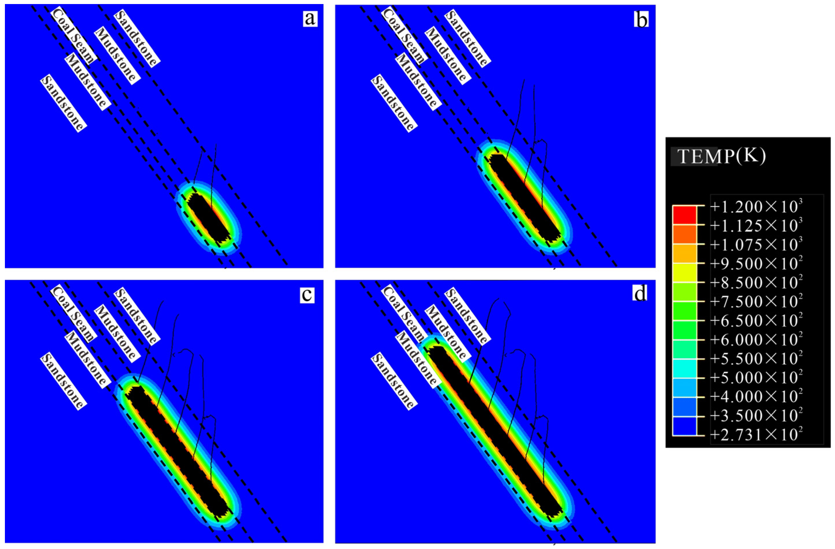
Along the gasification channel direction, the coal temperature field exhibited typical four-stage characteristics. Initially, under thermal conduction effects, the coal entered a heat-absorption and temperature-rise phase, forming a gradient-distributed temperature field through solid heat transfer. When the coal temperature reached the ignition point, it entered the precombustion stage. As oxidation reactions released significant exothermic heat, rock units continuously accumulated thermal energy, causing local temperatures to surpass the gasification reaction threshold and thereby establishing a gasification working face dominated by heterogeneous gas–solid reactions. Ultimately, as the combustible components were fully converted, the coal body was completely consumed, thereby forming a burned-out zone (Figure 6a).
During the stable advancement of the gasification working face, the roof mudstone could be subjected to sustained high temperatures up to 1000 °C, which aligned with previous research reporting gasification temperatures between 800 °C and 1200 °C [48,49]. Perpendicular to the gasification channel direction, the temperature field and combustion cavity expansion range continuously expanded with the advancing gasification working face. Rock units closer to the gasification center exhibited higher temperatures. This phenomenon was due to the fact that proximity to the gasification center resulted in greater thermal flux density entering the rock units, thereby absorbing more heat energy. When the combustion cavity length increased from 100 m to 400 m, the maximum temperature influence ranges were 26.67 m (Figure 6a), 27.22 m (Figure 6b), 27.78 m (Figure 6c), and 28.89 m (Figure 6d), respectively.
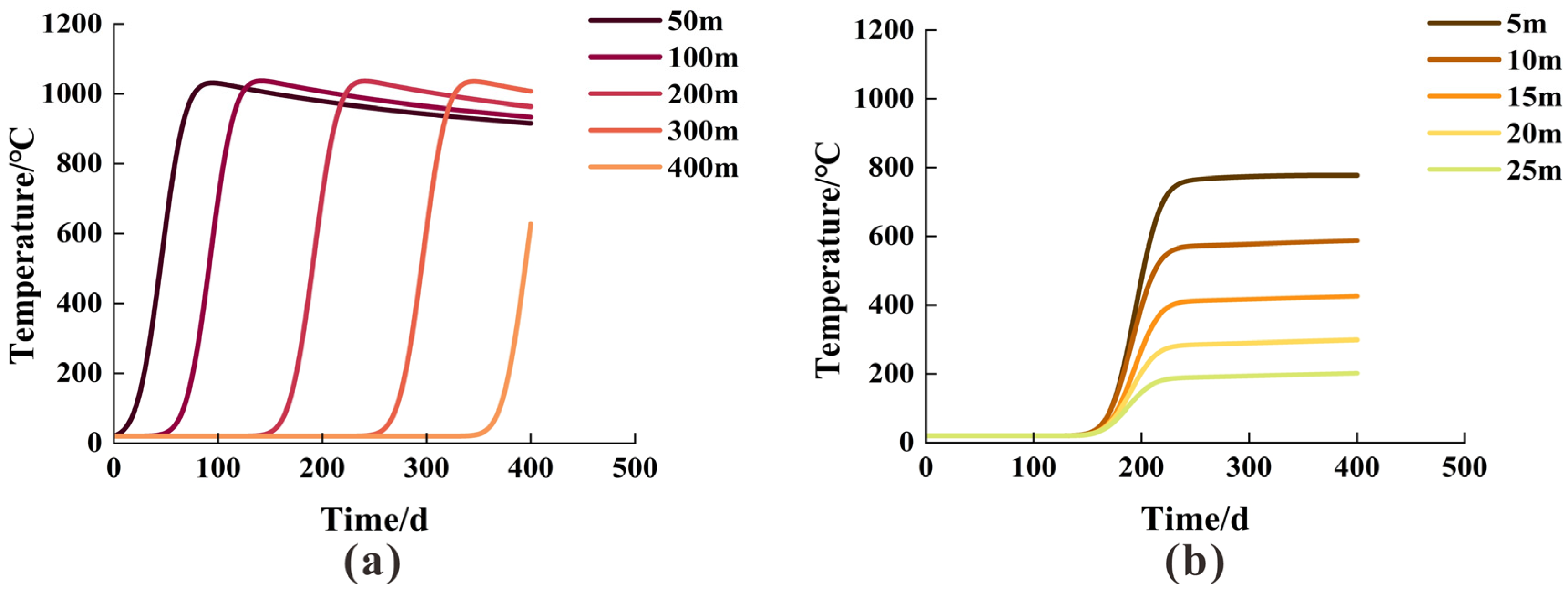
As the gasification front progressed, the temperature along the gasification boundary was maintained within approximately 1000–1200 °C, although its spatial distribution varied with distance from the ignition point. At a position 50 m from the initial gasification location, the roof mudstone experienced rapid thermal uptake, resulting in a sharp temperature increase to around 1000 °C. With continued advancement of the gasification front, the separation between this rock unit and the heat source increased, leading to a reduction in thermal input. Meanwhile, heat loss to the surrounding strata further contributed to a gradual temperature decline, after which the temperature tended toward a stable state. In contrast, the rock mass located 400 m from the starting point reached a considerably lower maximum temperature, primarily due to delayed thermal exposure and insufficient heating duration (Figure 7a).
During the initial stage of gasification, the rock unit at 200 m remained unaffected by the high temperatures from the gasification center and maintained its initial temperature of 20 °C. As the gasification face advanced, rock units entered an endothermic heating phase (Figure 7b). Lower-lying rock units, being closer to the gasification center, experienced higher heat flux and extremely rapid temperature rise, reaching peak temperatures of up to 800 °C (at a distance of 5 m from the gasification channel). Higher rock units could acquire heat only through thermal conduction, resulting in a delayed temperature response. In contrast, as elevation increased, the heat flux decreased significantly, while the temperature increased slowly, with the maximum temperature not exceeding 200 °C (at a distance of 25 m from the gasification channel).

5.2. Stress Field Evolution

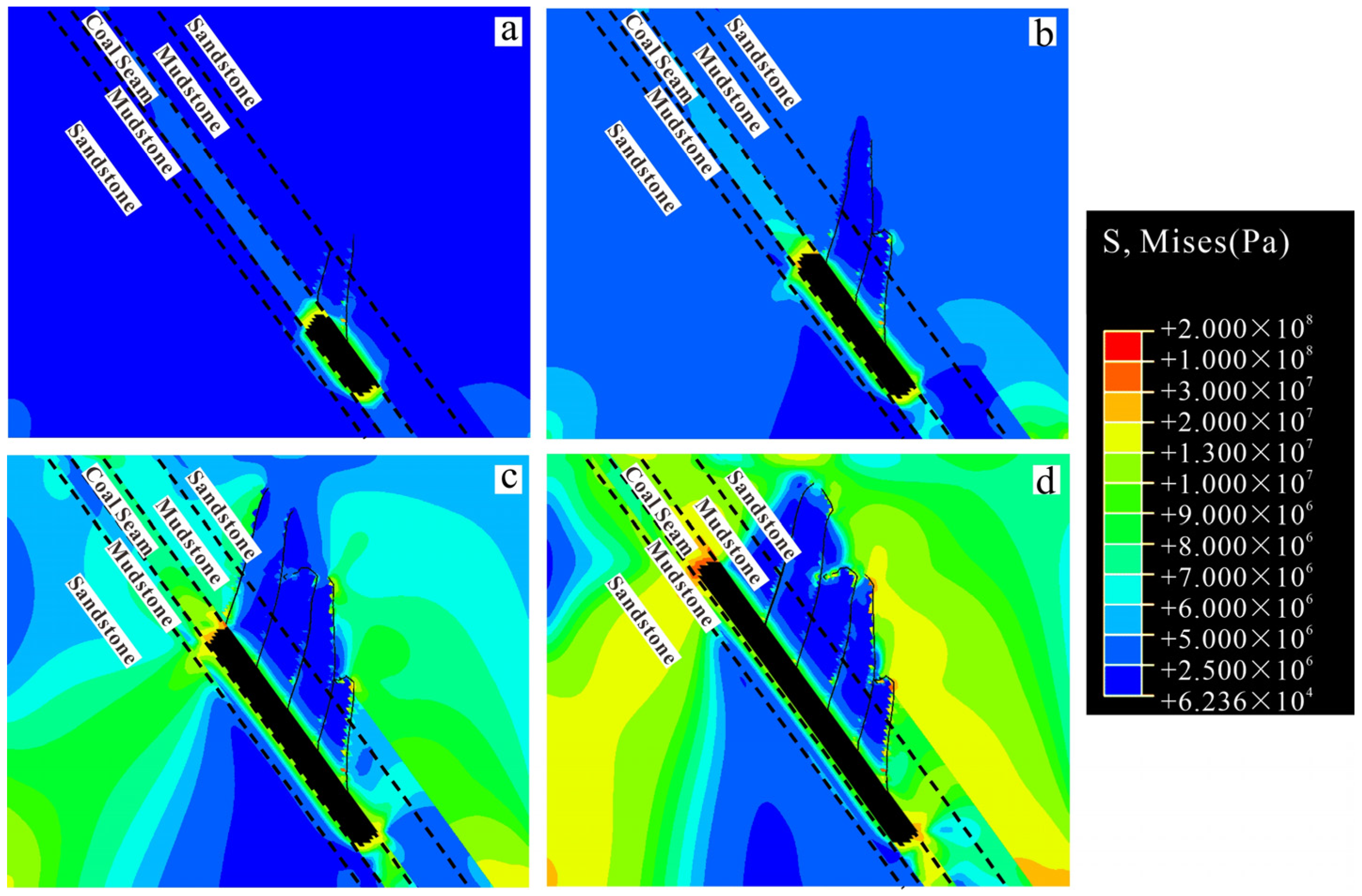
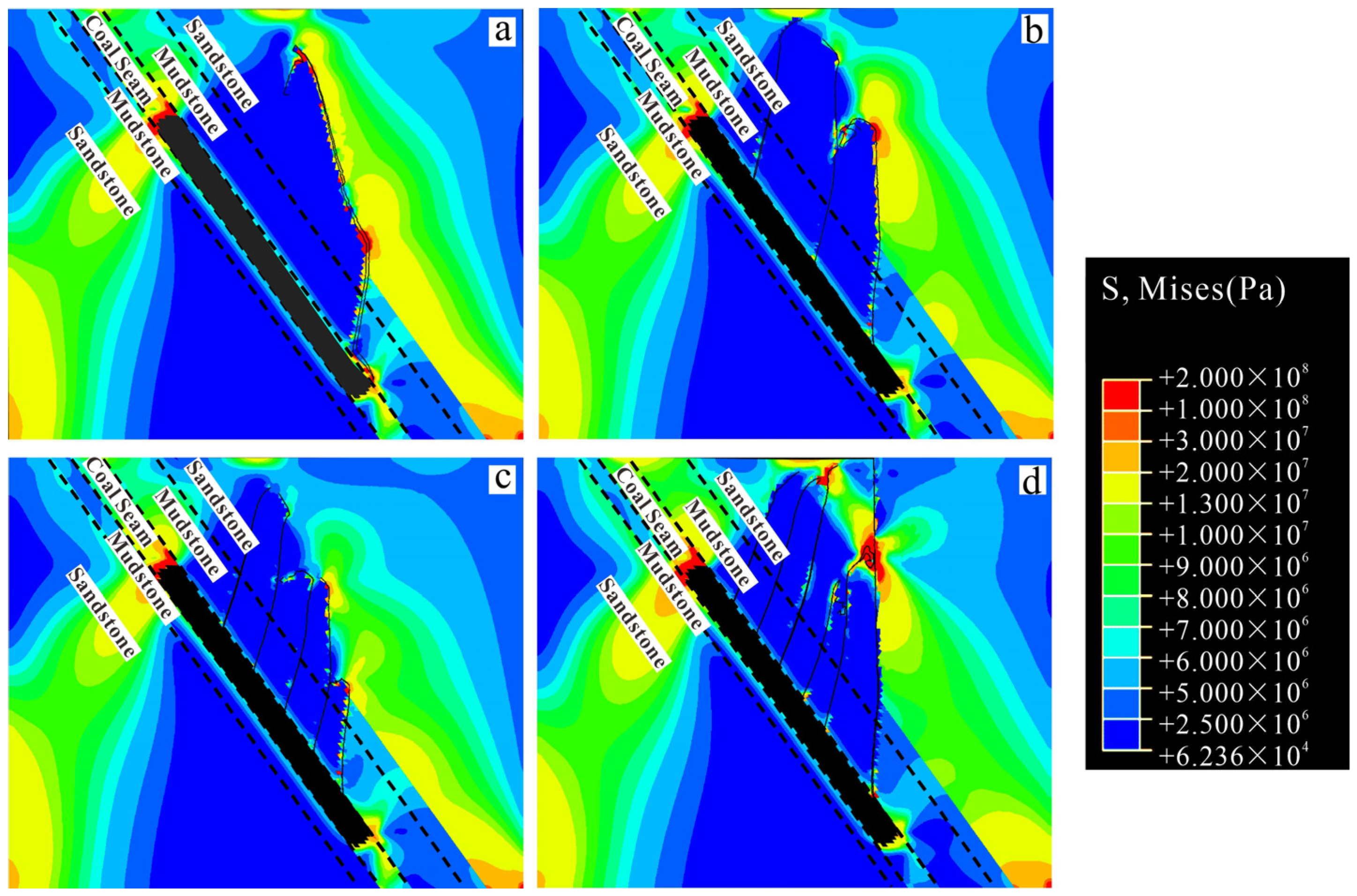
The original strata stress exhibited a continuous and uniform distribution. When the combustion cavity length extended to 100 m, however, the gasification cavity disrupted the continuity of the original stress transmission within the rock layers. Consequently, the stress flow lines underwent significant deflection at the corners of both ends of the gasification cavity, which led to a pronounced stress redistribution. Stress concentration zones formed within localized regions near the ends of the gasification cavity. Simultaneously, the thermal expansion stress generated in the heated roof mudstone partially offset the overburden stress transmitted from the overlying strata. As the combustion cavity length increased, the sustained application of the overlying strata pressure load exceeded the peak strength that the roof mudstone could withstand under the coupled effects of high temperature and stress, which initiated damage and failure. Driving by the stress field, the pre-existing weak zones (the first and second natural fractures) were the first to undergo fracture propagation (Figure 8a).
When the burnout cavity length reached 200 m, the stress field distribution exhibited significant spatial heterogeneity. The propagation of the stress field had a limited impact on rock units in the shallow regions, whereas significant propagation and evolution occurred in the deep regions. Under the combined effects of stress loading and high-temperature conditions, the roof rock units experienced progressive strength degradation and damage, thus driving the continued propagation of the first and second natural fractures. These fractures penetrated the relatively weak roof mudstone layer and extended upward into the overlying sandstone formation. The propagation of the first natural fracture was obstructed after extending a certain distance, thus causing its propagation path to deflect significantly and eventually trend toward a sub-horizontal direction. Simultaneously, the third natural fracture was rapidly initiated; this fracture penetrated the mudstone layer and extended into the sandstone formation (Figure 8b).
When the combustion cavity length reached 300 m, extensive stress concentration zones formed in the overlying strata of the deep gasification channel and the underlying strata of the shallow gasification channel. Stress concentration led to the penetration of the fourth and fifth natural fractures through the roof mudstone and caused them to extend into the overlying sandstone layer. Simultaneously, interactions between fractures became notably evident. The propagation of the fourth natural fracture exerted a significant pressure relief effect on the underlying rock mass. As a result, the propagation directions of the previously extended second and third natural fractures within the sandstone layer altered because of changes in the local stress state after extending a certain distance (Figure 8c). When the combustion cavity length reached 400 m, continuous stress accumulation and evolution occurred in the overlying strata of the deep gasification channel and the underlying strata of the shallow gasification channel. The propagation of natural fractures significantly redistributed the surrounding rock stress, which effectively released the rock mass stress within a certain range around the fractures. A pronounced pressure-relief zone developed below the fractures, evolving into a relatively low-stress region (Figure 8d).
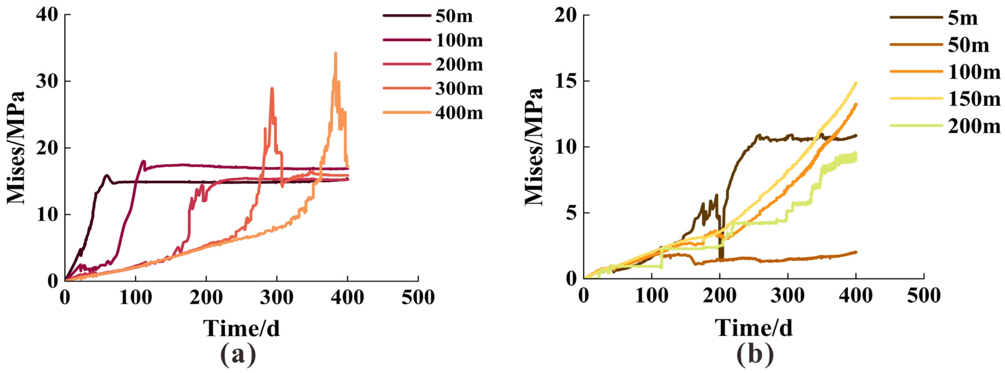
In the ABAQUS finite element software, Mises stress was an equivalent stress. As a scalar quantity, it comprehensively represented the stress level of rock materials under complex stress states and predicted when the rock material would begin to yield. Rock units closer to the gasification starting point experienced thermal damage and weakening earlier because of high-temperature effects. Meanwhile, with the dynamic propagation of the stress field, units at varying distances reached their peak stress sequentially. Although subsequent fracture propagation provided some stress relief, this effect had a limited impact on the high-stress state experienced by the rock units throughout the gasification process. After reaching their peak stress, the stress level in the rock units did not decrease significantly but stabilized at a level that was substantially higher than the initial state (Figure 9a).
Because of its spatial proximity to the gasification center, the mudstone unit at the roof 50 m from the gasification starting point within the gasification channel was the first to experience the dual effects of high temperatures from the gasification center and stress concentration induced by cavity formation. This effect led to the earliest and most rapid increase in its stress values. During the initial ascent phase, we observed a steep decline phase in the stress curve (Figure 9a). We attributed this phenomenon to the expansion of the first natural fracture, which exerted a decompression effect on the surrounding rock units, effectively releasing part of the stress. Under the combined driving forces of the sustained overburden pressure load and high temperature, however, the stress value of this mudstone unit rapidly reached its peak stress after a brief decrease.
As the gasification center progressively reached the mudstone unit locations at 100 m, 200 m, 300 m, and 400 m from the gasification starting point, their stress values correspondingly underwent an initially gradual increase followed by accelerated growth, sequentially attaining their respective peak stresses from near to far (Figure 9a). Simultaneously, the magnitude of the peak stress exhibited a clear distance-dependent behavior, with mudstone units farther from the gasification starting point achieving higher peak stresses. This phenomenon stemmed from the continuous evolution and propagation characteristics of the stress field. The further the mudstone unit was from the starting point, the longer it was subjected to stress disturbances, thereby resulting in a higher peak stress.
The rock layer located 5 m above the gasification channel, owing to its close proximity to the heat source, was the first to be exposed to elevated temperatures. The resulting thermal expansion induced additional stress that partially counteracted the in situ stress imposed by the overlying strata. As a result, this unit exhibited both the lowest stress magnitude and the slowest stress growth rate compared with rock units at other elevations. Once the coal seam was fully consumed and a gasification cavity developed, the mechanical support originally provided by the coal seam was eliminated. Under the combined effects of sustained high temperature and formation pressure, the stress within this rock unit increased rapidly to a peak value and subsequently reached a stable state.
The rock unit situated at a height of 50 m showed a gradual stress increase during the early stage, driven by the joint influence of thermal loading and formation pressure. However, following the upward propagation of the third and fourth natural fractures, stress relief occurred beneath these fractures, leading to a reduction in stress magnitude that persisted at a relatively low level.
In contrast, rock units located at heights of 100 m, 150 m, and 200 m were only weakly affected by stress redistribution and fracture development due to their greater distance from the gasification channel. Consequently, their stress levels generally displayed a continuous increasing trend. Among these three units, the layer at 200 m, being farthest from both the stress concentration zone and the fracture propagation region, exhibited the lowest overall stress values (Figure 9b).

5.3. Displacement Field Evolution

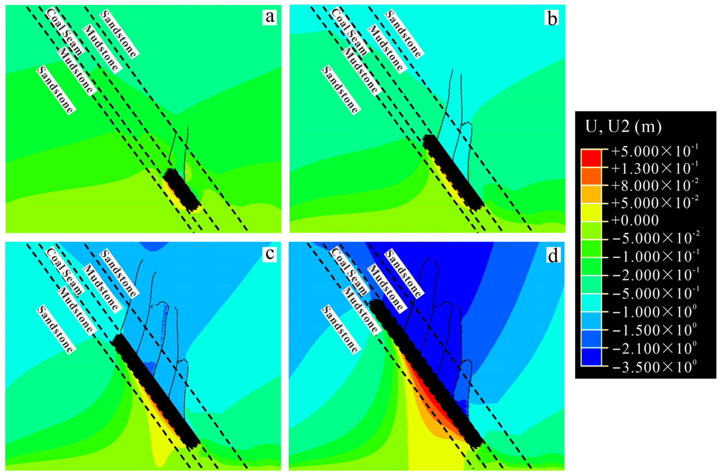
When the combustion cavity length reached 100 m, the displacement field had not yet fully developed, with only negligible displacements observed in most areas. The floor mudstone of the gasification cavity exhibited upward displacement as a result of thermal expansion from high temperatures, whereas the roof mudstone, despite also experiencing thermal expansion tendencies, showed minor downward displacement as a result of counteracting effects from overlying strata pressure. At this stage, the gasifier structure maintained good stability (Figure 10a). When the combustion cavity length reached 200 m, the thermal expansion range of the floor rock units expanded, intensifying upward displacement. Thermomechanical coupling effects triggered rapid propagation of the third fracture. Concurrently, the strength of the overlying strata degraded as a result of fracture propagation, leading to significant subsidence displacement around the fracture zone (up to 1.4 m), which reflected a systematic decline in the deformation resistance of the rock mass within the fracture-affected area (Figure 10b). When the combustion cavity length reached 300 m, the fourth and fifth fractures underwent interlinked propagation, creating an interconnected failure mechanism. Subsidence displacements in the shallow overlying strata were concentrated within the fracture-affected zones, with the maximum subsidence increasing to 2.0 m. Meanwhile, the deep floor rock units, subjected to sustained high temperatures, exhibited further expansion of the upward displacement zone with increased magnitude (reaching a maximum of 0.13 m; Figure 10c). When the combustion cavity length reached 400 m, the displacement field became fully developed. An intensively developed network of natural fractures propagated extensively, which significantly reduced the structural integrity of the rock mass. In the shallow overlying strata, sustained stress-induced damage caused rapid degradation of failure strength, resulting in substantial deformation. Large-scale subsidence displacements (up to 3.29 m) occurred within the fracture-affected zones. At this stage, the overlying strata in the fractured area reached a critical instability state, which posed risks such as partial collapse blocking the gasification channel and surface deformation hazards as a result of strata settlement transmission. These factors may have compromised the safe and stable operation of the gasifier (Figure 10d).
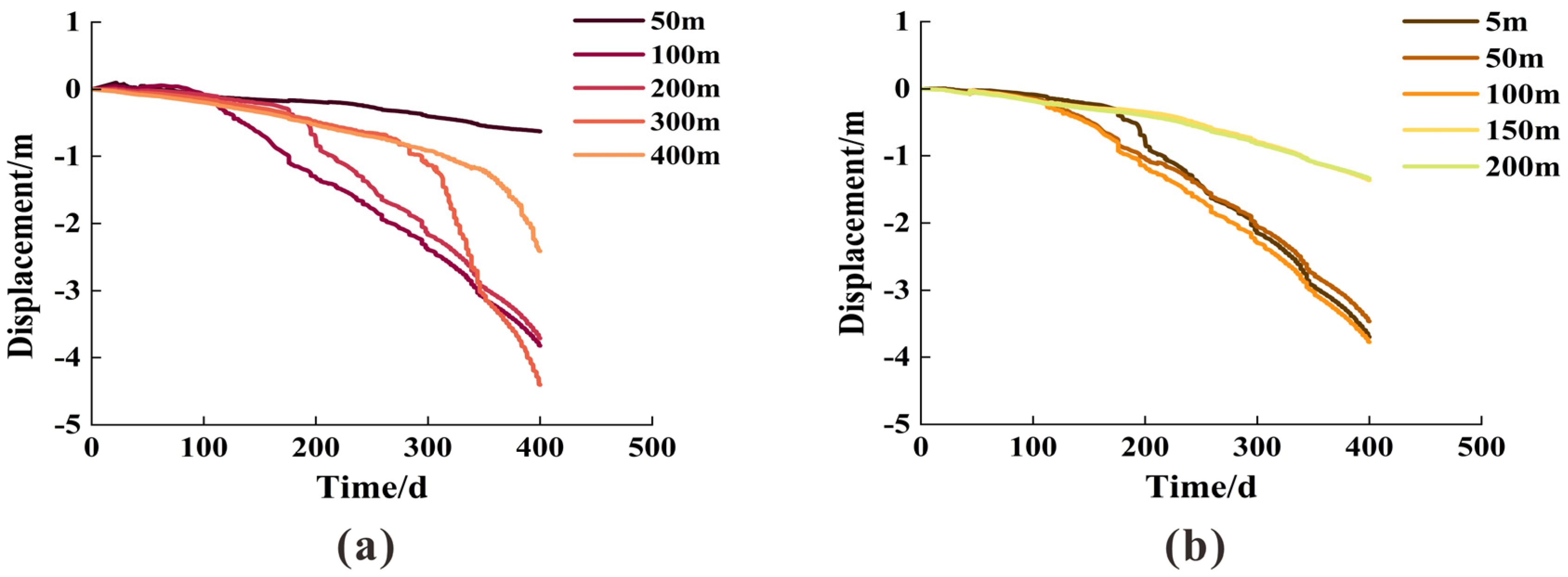
Figure 11a reveals the evolution pattern of roof mudstone subsidence displacement with distance from the gasification starting point along the channel. This pattern demonstrated that all mudstone units experienced progressive settlement as a result of continuous loading from overburden stress. When the combustion cavity length reached 50 m, a gasification cavity first formed beneath this area. The stress generated by thermal expansion in the overlying mudstone partially offset the vertical pressure from the overburden, ensuring that subsidence displacement remained at a relatively low level. As the combustion cavity length extended to 100 m, 200 m, 300 m, and 400 m, the second to fifth fractures progressively propagated upward into the roof mudstone units, which resulted in significant local stress concentration, and the extensive fracture development led to a reduction in the overall strength of the rock strata, generating substantial deformation. Consequently, the subsidence displacements of rock units at different locations exhibited stepped increases from near to far. This phenomenon validated that fracture propagation was the key factor triggering abrupt and significant changes in the displacement of the gasification channel roof and overlying strata.
Figure 11b reveals the variation pattern with height of rock units at different elevations perpendicular to the gasification channel when the combustion cavity length reached 200 m. During the initial gasification stage, lower-elevation rock units, being closer to the gasification center, were the first to be affected by the high temperatures from the coal gasification reaction. Consequently, the roof mudstone at 5 m height absorbed heat, expanded, and generated stress, which significantly offset the formation pressure from the overlying strata and inhibited subsidence displacement. This suppressive effect on subsidence displacement diminished with increasing elevation. During the late stage of gasification, medium- to low-elevation rock units at heights of 5 m and 10 m experienced substantial deformation and loss of structural stability as a result of the upward propagation of natural fractures above them. This deformation resulted in a significant short-term increase in subsidence displacement, thus producing a sharp inflection point in the settlement curve. In contrast, rock units above 100 m elevation, which were located far from the fracture-affected zone and primarily were subjected to continuous loading from the overlying strata stress field, exhibited a steady and gradual downward displacement trend.

5.4. Implications of Induced Fractures on Stress Field Evolution

On the basis of the aforementioned numerical model of UCG of SICS, we conducted a comparative analysis to investigate the influence of the dynamic propagation of induced fractures under varying development degrees of natural fractures (zero, three, five, and seven fractures) on the evolution patterns of the stress field. Although the pre-existing natural fracture densities in the models varied significantly, the overall distribution patterns of the overlying strata stress field exhibited similar characteristics. High-stress concentration zones were primarily distributed in the shallow underlying strata of the gasification channel, the deep overlying strata of the gasification channel, as well as near both ends of the channel. In the model without pre-existing natural fractures (zero fracture), the coupled thermomechanical effects primarily induced the initiation and limited propagation of fractures along the inherent weak structures within the rock mass. Concurrently, the macroscopic damage degree of the rock remained relatively low, and the overall structure of the overlying strata retained a relatively high deformation resistance, effectively suppressing the phenomenon of cross-layer fracture penetration.
As the number of pre-existing natural fractures increased, their accelerated propagation behavior driven by thermomechanical coupling significantly exacerbated the accumulation of progressive damage in the overall structure of the overlying strata. The propagation of pre-existing natural fractures not only served as the dominant failure pathway but also synergistically induced large-scale plastic deformation within the rock strata. The constraining effectiveness of the overlying strata on fracture propagation was significantly weakened, allowing fractures to more readily penetrate interlayer boundaries and ultimately to trigger cross-layer propagation. This propagation contributed to the formation of potential interconnected water- and gas-conducting fracture channels. In the context of SICS, because of asymmetric load distribution and the distinct characteristics of strata occurrence, the evolution path of this phenomenon became increasingly complex, and the associated production safety risks were substantially heightened (Figure 12).

5.5. The Limited Length of Gasification Channel Considering Overlying Strata Fractures’ Propagation

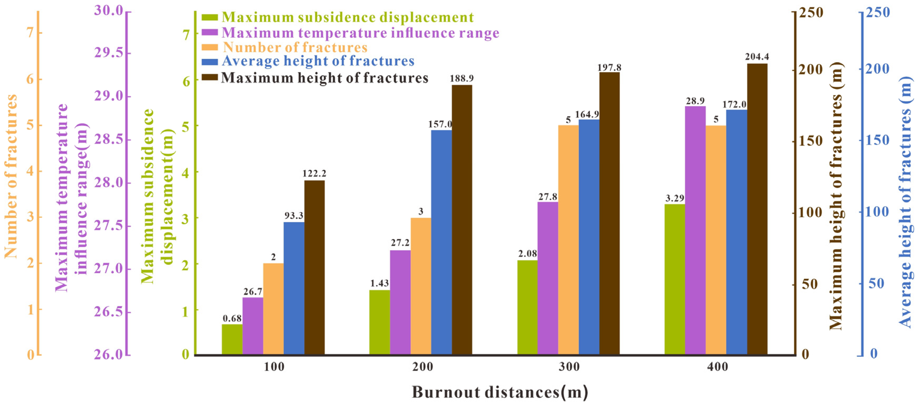
Table 3 and Figure 13 summarizes the number of the induced overlying strata fractures, propagation height, maximum subsidence displacement, and maximum temperature influence range for the model with five pre-existing natural fractures under different combustion cavity lengths. Among the configurations examined, the 400 m cavity exhibited the most extensive influence, with an average fracture height of 172 m, a maximum subsidence displacement of 3.29 m, and a temperature influence range extending up to 28.89 m.
Notably, it was observed that the natural fractures initiated propagation even before the combustion cavity had advanced to a position directly beneath them.
In the study area, the coal-bearing sequence comprises an interbedded arrangement of aquifers and aquitards. When the combustion cavity reached 400 m, the average fracture height approached 200 m, sufficient to penetrate multiple aquifer layers. Although individual aquifers exhibit limited water-bearing capacity, the interconnection of the induced fractures across several strata can facilitate groundwater convergence, forming continuous flow pathways [50]. This process elevates the risk of water intrusion into the gasifier, threatening operational stability and overall project safety.
Therefore, in practical UCG design within this geological setting, the gasifier length should be carefully optimized. The 100 m cavity is considered economically inefficient due to insufficient coal volume for gasification, while longer cavities (300 m and 400 m), though enabling more fully developed reaction zones, pose significant safety risks from excessive overlying strata failure and fracture connectivity. It is recommended that the gasifier length not exceed 200 m. It should be noted that the upper limit of gasification channel length proposed in this study and its corresponding safety criteria are derived from the results of two-dimensional model analysis, reflecting trend-based responses under the current model configuration and geological conditions. For actual engineering design, comprehensive assessment is still required, incorporating three-dimensional structural features, spatial heterogeneity of overlying strata, and field monitoring data. Moreover, the overlying strata must possess adequate deformation resistance and natural sealing capacity to maintain gasifier integrity, prevent gas leakage, and safeguard groundwater resources. Thus, meticulous geological and geotechnical site selection, along with a detailed assessment of aquifer distribution and its spatial relationship to the target coal seam, is essential to avoid zones prone to water inflow or with pre-existing fracture networks.
To provide a preliminary quantitative assessment of the potential water and gas conductivity risks associated with induced fractures, this study introduces a simplified criterion based on the upward propagation height of the damage zone. This criterion uses the ratio of the maximum upward propagation height of the damage zone to the vertical distance between the gasification cavity (Hf) and the critical overlying stratum (Haq) as a risk indicator. This ratio characterizes the extent to which the fracture system approaches a potential water-conducting layer. When this ratio is relatively small, the fractures have not yet caused significant disturbance to the overlying critical layer, indicating a relatively low risk of water and gas conductivity. Conversely, when the ratio approaches or exceeds 1, it indicates that the damage zone has neared or reached the target stratum, posing a high potential risk of connectivity.
H R C = H f H a q
where Hf is the maximum fracture propagation height, m; Haq is the vertical distance from the top of the gasification cavity to the top of the model, m.
Based on the above formula, it can be concluded that when the burnout cavity length is 300 m, the HRC is greater than 1, whereas when the burnout cavity length is 200 m, the HRC is less than 1. Therefore, 200 m is determined to be the safe length.

6. Conclusions

In this study, a multiphysics coupled evolution model was developed to simulate underground coal gasification (UCG) under in situ geological conditions, targeting a coal seam with a dip angle of 53° in the steeply inclined coal seam (SICS) of the Fukang mining area, Xinjiang, China. Through numerical simulations of UCG of SICS, we investigated the multi-field coupling characteristics of the gasification channel and the development and evolution patterns of the induced fractures in the overlying strata under different combustion cavity lengths. The following conclusions were drawn:
(1)
The maximum influence range of the temperature field varied with different combustion cavity lengths. A longer combustion cavity length resulted in a greater expansion range of the temperature field. Perpendicular to the gasification channel direction, rock units at lower elevations of SICS tended to heat up more rapidly. As the combustion cavity length increased from 100 m to 400 m, the expansion ranges of the temperature field in the shallow and deep sections extended from 15.56 m to 26.67 m and from 17.78 m to 28.89 m, respectively.
(2)
UCG of SICS induced intense thermomechanical coupling effects, driving significant spatial redistribution of the strata stress field, while fracture propagation was accompanied by notable local pressure relief. Rock units near the gasification starting point exhibited early response and low peak stress characteristics, whereas those near the gasification endpoint demonstrated late response and high peak stress characteristics. When the combustion cavity length reached 400 m, the maximum height of the induced fractures reached 204.44 m, with an average height of 172 m.
(3)
The floor mudstone experienced upward displacement as a result of thermal expansion, whereas the roof and overlying strata underwent downward displacement caused by rock layer deformation resulting from fracture propagation. The magnitude of this displacement demonstrated stepped increases over time, reaching a maximum subsidence of 3.29 m upon completion of the gasification process.
(4)
Fracture propagation is the primary factor leading to abrupt displacement in rock strata and a sharp decline in bearing capacity, and it is inferred that this may induce hazards such as roof collapse and surface subsidence. Therefore, in the practical design of UCG projects for steeply inclined coal seams within the study area, it is recommended that the gasification channel length not exceed 200 m to mitigate the aforementioned risks. The relevant conclusions of this study can provide theoretical guidance and technical support for the preliminary design of UCG cavities in steeply inclined coal seams. It should be noted that the prediction of groundwater inflow risks may require dedicated hydrogeological analysis for a comprehensive assessment. Future work aims to enhance the predictive capability for multi-field coupling processes and safety design parameters in practical UCG applications.

Author Contributions

Conceptualization, J.L. and X.L.; Software, J.L. and X.L.; Formal analysis, J.L. and X.L.; Writing—original draft, J.L.; Writing—review and editing, X.L., S.Y. and S.S.; investigation, Z.W. and B.Z. All authors have read and agreed to the published version of the manuscript.

Funding

This study was supported by the Key Research and Development Program of the Xinjiang Uygur Autonomous Region (2024B03002), the National Major Science and Technology Program (2024ZD14000), Xinjiang Uygur Autonomous Region Major Science and Technology Program (202203015-2).

Institutional Review Board Statement

Not applicable.

Informed Consent Statement

Not applicable.

Data Availability Statement

The data used to support this study are available from the corresponding author upon request.

Acknowledgments

Special thanks go to the members of my research team for their collaboration and contributions.

Conflicts of Interest

The authors declare no conflicts of interest.

References

  1. Perkins, G. Underground coal gasification—Part I: Field demonstrations and process performance. Prog. Energy Combust. Sci. 2018, 67, 158–187. [Google Scholar] [CrossRef]
  2. Khan, M.; Mmbaga, J.; Shirazi, A.; Trivedi, J.; Liu, Q.; Gupta, R. Modelling underground coal gasification—A review. Energies 2015, 8, 12603–12668. [Google Scholar] [CrossRef]
  3. Chen, X.; Zhao, S.; Liu, Z.; Chen, G. Research on evaluation technology system of mid-deep underground coal gasification based on researchers from China. Heliyon 2024, 10, e33248. [Google Scholar] [CrossRef] [PubMed]
  4. Wang, Y.; Sun, Q.; Wu, J.; Han, S.; Zhang, R.; Jiang, S.; Gu, X. Research on the low carbon development path of China’s coal industry under carbon peaking & carbon neutral target: Based on the RCPs-SSPs framework. Resour. Policy 2023, 86, 104091. [Google Scholar] [CrossRef]
  5. Kačur, J.; Laciak, M.; Durdán, M.; Flegner, P. Investigation of underground coal gasification in laboratory conditions: A review of recent research. Energies 2023, 16, 6250. [Google Scholar] [CrossRef]
  6. Ju, Y.; Zhu, Y.; Xie, H.P.; Nie, X.; Zhang, Y.; Lu, C.; Gao, F. Fluidized mining and in-situ transformation of deep underground coal resources: A novel approach to ensuring safe, environmentally friendly, low-carbon, and clean utilisation. Int. J. Coal Sci. Technol. 2019, 6, 184–196. [Google Scholar] [CrossRef]
  7. Teng, X.Y.; Zhuang, W.W.; Liu, F.P.; Chang, T.H.; Chiu, Y.H. China’s path of carbon neutralization to develop green energy and improve energy efficiency. Renew. Energy 2023, 206, 397–408. [Google Scholar] [CrossRef]
  8. Xiong, Y.; Kong, D.; Song, G. Research hotspots and development trends of green coal mining: Exploring the path to sustainable development of coal mines. Resour. Policy 2024, 92, 105039. [Google Scholar] [CrossRef]
  9. Liu, Y.; Liu, S.; Liu, Z.; Li, X.; Cao, J.; Qi, C.; Wang, W. Pore structure evolution of semi-coke under steam atmosphere in the context of deep underground coal gasification. Fuel Process. Technol. 2025, 278, 108329. [Google Scholar] [CrossRef]
  10. Liu, R.; Zhang, Y.; Ling, Z.; Song, Y. Some new insights into the synergy occurring during char gasification in CO2/H2O mixtures. Fuel 2020, 268, 117307. [Google Scholar] [CrossRef]
  11. Guo, W.; Liu, H.; Chang, Z.; Cao, D.; Liu, S. Study on effects of thermal resistance and thermal buoyancy on oxygen flow Patterns during underground coal gasification. ACS Omega 2021, 6, 32977–32986. [Google Scholar] [CrossRef]
  12. Bhutto, A.W.; Bazmi, A.A.; Zahedi, G. Underground coal gasification: From fundamentals to applications. J. Prog. Energy Combust. Sci. 2013, 39, 189–214. [Google Scholar] [CrossRef]
  13. Liu, S.Q.; Shi, S.Z.; Feng, G.X.; Feng, J.; Li, M.X.; Guo, W. Geological site selection and evaluation for underground coal gasification. J. China Coal Soc. 2019, 8, 2531–2538. [Google Scholar] [CrossRef]
  14. Guo, W.; Liu, H.; Zhu, X.; Zhang, Y.; Liu, S.; Guo, T. Research on the expansion law of combustion cavity in deep coal seam underground gasification based on multi-physics field simulations and response surface method. Energy 2025, 326, 136287. [Google Scholar] [CrossRef]
  15. Yuan, L.; Jiang, Y.; Wang, K.; Zhao, Y.; Hao, X.; Xu, C. Precision exploitation and utilization of closed/abandoned mine resources in China. J. China Coal Soc. 2018, 43, 14–20. [Google Scholar]
  16. Feng, Y.; Yang, B.; Hou, Y.; Duan, T.-H.; Yang, L.; Wang, Y. Comparative environmental benefits of power generation from underground and surface coal gasification with carbon capture and storage. J. Clean. Prod. 2021, 310, 127383. [Google Scholar] [CrossRef]
  17. Su, F.Q.; Itakura, K.I.; Deguchi, G.; Ohga, K. Monitoring of coal fracturing in underground coal gasification by acoustic emission techniques. Appl. Energy 2017, 189, 142–156. [Google Scholar] [CrossRef]
  18. Falshtynskyi, V.S.; Dychkovskyi, R.O.; Lozynskyi, V.G.; Saik, P.B. Determination of the technological parameters of borehole under-ground coal gasification for thin coal seams. J. Sustain. Min. 2013, 12, 8–16. [Google Scholar] [CrossRef]
  19. Jiang, L.L.; Chen, Z.X.; Farouq Ali, S.M. Feasibility of carbon dioxide storage in post-burn underground coal gasification cavities. Appl. Energy 2019, 252, 113479. [Google Scholar] [CrossRef]
  20. Frejowski, A.; Bondaruk, J.; Duda, A. Challenges and opportunities for end-of-life coal mine sites: Black-to-green energy APPROACH. Energies 2021, 14, 1385. [Google Scholar] [CrossRef]
  21. Tang, C.; Li, H.; Guo, G.; Cao, J.; Zha, J.; Li, R. A new paradigm for safe and accurate design of underground coal gasification coal pillars based on physics-informed neural networks. Eng. Appl. Artif. Intell. 2025, 160, 111957. [Google Scholar] [CrossRef]
  22. Wang, D.; Tian, J.; Yang, S.; Zou, J.; Wei, B.; Li, X.; Tong, H.; Zhang, Y.; Xu, C. Research review of underground coal gasification: Principles, challenges and prospects. Fuel 2026, 406, 136823. [Google Scholar] [CrossRef]
  23. Durucan, S.; Korre, A.; Shi, J.Q.; Idiens, M.; Stańczyk, K.; Kapusta, K.; Mastalerz, M. Tops: Technology options for coupled underground coal gasification and CO2 capture and storage. Energy Procedia 2014, 63, 5827–5835. [Google Scholar] [CrossRef]
  24. Zou, C.; Chen, Y.; Kong, L.; Sun, F.; Chen, S.; Dong, Z. Underground coal gasification and its strategic significance to the development of natural gas industry in China. Pet. Explor. Dev. 2019, 46, 205–215. [Google Scholar] [CrossRef]
  25. Zhang, H.; Xiao, Y.; Luo, G.; Fang, C.; Zou, R.; Zhang, Y.; Li, X.; Yao, H. Numerical simulation study on chemical ignition process of underground coal gasification. Energy 2024, 298, 131350. [Google Scholar] [CrossRef]
  26. Chandelle, V.; Jacquemin, C.; Létolle, R.; Mostade, M.; Pirard, J.-P.; Somers, Y. Underground coal gasification on the thulin site: Results of analysis from post-burn drillings. Fuel 1993, 72, 949–963. [Google Scholar] [CrossRef]
  27. Wang, J.; Wang, Z.; Xin, L.; Xu, Z.; Gui, J.; Lu, X. Temperature field distribution and parametric study in underground coal gasification stope. Int. J. Therm. Sci. 2017, 111, 66–77. [Google Scholar] [CrossRef]
  28. Ekneligoda, T.; Marshall, A. A coupled thermal-mechanical numerical model of underground coal gasification (UCG) including spontaneous coal combustion and its effects. Int. J. Coal Geol. 2018, 199, 31–38. [Google Scholar] [CrossRef]
  29. Li, H.; Cao, J.; Tang, C.; Guo, G.; Chen, Y.; Zha, J.; Huang, W.; Yuan, Y.; Huang, J. Methods for enhancing resource recovery efficiency in underground coal gasification to promote its large-scale utilization. Geomech. Energy Environ. 2025, 41, 100651. [Google Scholar] [CrossRef]
  30. Prabu, V.; Jayanti, S. Simulation of cavity formation in underground coal gasification using bore hole combustion experiments. Energy 2011, 36, 5854–5864. [Google Scholar] [CrossRef]
  31. Li, J.; Bai, J.W.; Feng, G.R.; Yilmaz, E.; Han, Y.; Wang, Z.; Wu, G. Degradation mechanism of coal pillars in an underground coal gasification environment: Bearing capacity, pyrolysis behaviour and pore structure. Int. J. Min. Sci. Technol. 2025, 35, 897–912. [Google Scholar] [CrossRef]
  32. Zhang, F.; Wang, S.; Qiao, M.; Duan, Y.; Chen, W.; Li, J.; Li, Y. Experiment and simulation assessment of supercritical underground coal gasification in deep coal seam. Int. J. Hydrogen Energy 2024, 79, 974–985. [Google Scholar] [CrossRef]
  33. Biswas, A.K.; Islam, R.; Habib, A. An analytical investigation of critical factors to prioritize coalfields for underground coal gasification—Bangladesh case. Heliyon 2023, 9, e18416. [Google Scholar] [CrossRef]
  34. Ngo, D.; Pellet, F. Numerical modeling of thermally-induced fractures in a large rock salt mass. J. Rock Mech. Geotech. Eng. 2018, 10, 844–855. [Google Scholar] [CrossRef]
  35. Li, W.; Liu, J.; Xin, L.; Fan, J.; Wang, X.; Ma, Y.; Cheng, W.; Sui, J.; Niu, M. Numerical simulation of temperature field evolution and distribution range during movement of underground coal gasification working face. Energies 2025, 18, 931. [Google Scholar] [CrossRef]
  36. Jafarian, M.; Haseli, P.; Saxena, S.; Dally, B. Emerging technologies for catalytic gasification of petroleum residue derived fuels for sustainable and cleaner fuel production—An overview. Energy Rep. 2023, 9, 3248–3272. [Google Scholar] [CrossRef]
  37. Wang, Y.; Djordjevic, N. Thermal stress FEM analysis of rock with microwave energy. Int. J. Miner. Process. 2014, 130, 74–81. [Google Scholar] [CrossRef]
  38. Zhao, P.; Liu, J.; Elsworth, D. Numerical study on a multifracture enhanced geothermal system considering matrix permeability enhancement induced by thermal unloading. Renew. Energy 2023, 203, 33–44. [Google Scholar] [CrossRef]
  39. Zhou, X.P.; Bi, J. Numerical Simulation of thermal cracking in rocks based on general particle dynamics. J. Eng. Mech. 2017, 144, 04017156. [Google Scholar] [CrossRef]
  40. Hou, P.; Liang, X.; Gao, F.; Dong, J.; He, J.; Xue, Y. Quantitative visualization and characteristics of gas flow in 3D pore-fracture system of tight rock based on Lattice Boltzmann simulation. J. Nat. Gas Sci. Eng. 2021, 89, 103867. [Google Scholar] [CrossRef]
  41. Jiang, L.; Chen, Z.; Ali, S.F. General hydro-geological impact of cleats on underground coal gasification. Fuel 2018, 224, 128–137. [Google Scholar] [CrossRef]
  42. Cui, C.; Liu, Y.; Chai, X.; Tian, L. Investigation on performance characteristics and thermal analysis of underground coal gasification in porous media based on non-steady flow. Fuel 2025, 389, 134629. [Google Scholar] [CrossRef]
  43. Zhao, M.D. Experimental and Numerical Simulation Research on Temperature and Cracks of Overlying Rock for Underground Coal Gasification; China University of Mining and Technology: Beijing, China, 2017. [Google Scholar]
  44. Duan, T.-H.; Zhang, J.-M.; Mallett, C.; Li, H.-H.; Huo, L.-W.; Zhao, K.-T. Numerical simulation of coupled thermal-mechanical fracturing in underground coal gasification. Proc. Inst. Mech. Eng. Part A J. Power Energy 2018, 232, 74–84. [Google Scholar] [CrossRef]
  45. Zhang, Z.; Yang, X.; Shang, X.; Yang, H. A Thermal-hydrological-mechanical-chemical coupled mathematical model for underground coal gasification with random fractures. Mathematics 2022, 10, 2835. [Google Scholar] [CrossRef]
  46. Wang, X.R.; Zhang, Q.H.; Yuan, L. A coupled thermal-force-chemical-displacement multi-field model for underground coal gasification based on controlled retraction injection point technology and its thermal analysis. Energy 2024, 293, 130614. [Google Scholar] [CrossRef]
  47. Yao, X.; Li, X.; Wei, B.; Tian, J.; Yang, S.; Ju, Y. Numerical simulations of fracture propagation in overlying strata for deep underground coal gasification using controlled retraction injection point technology. Energy 2025, 317, 134684. [Google Scholar] [CrossRef]
  48. Wang, J.; Zu, Z.; Wang, Z.; Xu, G. The design of ignition systems and a study of the development of the high temperature zone in well-type underground coal gasification. Fuel 2020, 269, 117281. [Google Scholar] [CrossRef]
  49. Su, F.-Q.; Yang, J.-N.; He, X.-L.; Dai, M.-J.; Hamanaka, A.; Yu, Y.H.; Li, W.; Li, J.-Y. Influences of removable gas injection methods on the temperature field and gas composition of the underground coal gasification process. Fuel 2024, 363, 130953. [Google Scholar] [CrossRef]
  50. Quan, F.; Lu, W.; Song, Y.; Sheng, W.; Qin, Z.; Luo, H. Multifractal characterization of heterogeneous pore water redistribution and its influence on permeability during depletion: Insights from centrifugal NMR analysis. Fractal Fract. 2025, 9, 536. [Google Scholar] [CrossRef]
Figure 1. Geological framework of the Fukang mining area and the corresponding stratigraphic column of coal-bearing formations in well block Y1.
Energies 19 00559 g001
Figure 2. Two-dimensional numerical model of UCG in SICS.
Energies 19 00559 g002
Figure 3. Temperature variation curves at the midpoint of gasification channels with different mesh numbers over time.
Energies 19 00559 g003
Figure 4. Natural fracture development in the target coal seam and roof rock. (a,b) in situ roof rock, (c) roof rock sample, and (df) bulk coal samples. The yellow dashed line represents natural fracture.
Energies 19 00559 g004
Figure 5. Pre-existing natural fractures.
Energies 19 00559 g005
Figure 6. Evolution law of temperature field in the gasification channel under different burnout cavity lengths: (a) 100 m, (b) 200 m, (c) 300 m, and (d) 400 m.
Energies 19 00559 g006
Figure 7. (a) Temperature evolution of roof mudstone at various distances from the gasification initiation point along the gasification channel, and (b) temperature evolution of rock strata at different heights perpendicular to the gasification channel at 200 m from gasification initiation point.
Energies 19 00559 g007
Figure 8. Evolution law of stress field in the gasification channel under different burnout cavity lengths: (a) 100 m, (b) 200 m, (c) 300 m, and (d) 400 m.
Energies 19 00559 g008
Figure 9. (a) Stress evolution of roof mudstone at various distances along the gasification channel measured from the gasification initiation point, and (b) stress evolution of rock layers at different vertical elevations perpendicular to the gasification channel at a location 200 m downstream of the gasification initiation point.
Energies 19 00559 g009
Figure 10. Evolution law of displacement field in the gasification channel under different burnout cavity lengths: (a) 100 m, (b) 200 m, (c) 300 m, and (d) 400 m.
Energies 19 00559 g010
Figure 11. (a) Displacement evolution of roof mudstone at various distances along the gasification channel measured from the gasification initiation point, and (b) displacement evolution of rock layers at different vertical elevations perpendicular to the gasification channel at a position 200 m downstream of the gasification initiation point.
Energies 19 00559 g011
Figure 12. Evolution characteristics of stress fields in rock masses with naturally fractured networks of varying development degrees: (a) without pre-existing natural fractures (zero fracture), (b) three natural fractures, (c) five natural fractures, and (d) seven natural fractures.
Energies 19 00559 g012
Figure 13. Comparative bar chart of overlying strata fractures’ development under varying gasification channel lengths.
Energies 19 00559 g013
Table 1. Fundamental model parameters.
ProjectValueProjectValue
Model length/width600 m/500 mGasification channel length400 m
Coal seam thickness30 mGrid size5 m × 5 m
Burial depth of coal seam midpoint along the gasification channel887 mGasification advance rate1 m/d
Total number of grids14,669Multi-physics couplingtemperature-stress-
displacement-fracture
Table 2. Physical and mechanical properties of coal and surrounding rock materials.
LithologyDensity
Ρ (kg/m3)
Poisson’s Ratio
ν
Elastic
Modulus
E(GPa)
Thermal Expansion Coefficient
αt (10−6·K−1)
Thermal
Conductivity
λ(W/(m∙K))
Specific Heat Capacity
Cp(J/(Kg∙K))
Coal seam1306 *0.26 *5.92 *5 *0.26 *1188 *
Sandstone2650 *0.17 *1.68 *6 *2.9 *860 *
Mudstone2780 *0.16 *2.78 *9 *1.2 *750 *
Note: * refers to the measured average value.
Table 3. Comparative analysis of overlying strata fractures’ development under varying gasification channel lengths.
Burnout Distances (m)100200300400
Number of fractures2355
Maximum height of fractures (m)122.22188.89197.78204.44
Average height of fractures (m)93.33157.03164.89172
Maximum subsidence
displacement (m)
0.681.432.083.29
Maximum temperature influence range (m)26.6727.2227.7828.89
Disclaimer/Publisher’s Note: The statements, opinions and data contained in all publications are solely those of the individual author(s) and contributor(s) and not of MDPI and/or the editor(s). MDPI and/or the editor(s) disclaim responsibility for any injury to people or property resulting from any ideas, methods, instructions or products referred to in the content.