1. Introduction
Electrical power distribution networks have undergone significant changes as a result of the introduction of power electronic converters and renewable energy systems. Nowadays, a variety of technologies are used in commercial, industrial, and residential contexts, such as switched-mode power supply, variable-speed drives, and Electric Vehicle (EV) charging stations. The aforementioned advances improve operational efficiency, but because of their nonlinear behavior, they disrupt power quality [
1,
2,
3].
Nonlinear loads typically draw non-sinusoidal currents from the grid, which can result in harmonic distortion, current imbalance, and reactive power consumption. These effects degrade the quality of power delivered to end users, while also increasing system losses, and may cause overheating or malfunction of sensitive equipment. As a result, maintaining high power quality has become a critical requirement in modern low-voltage distribution networks [
4,
5,
6].
Traditionally, passive filters have been widely used to mitigate harmonic distortion, mainly due to their simple structure and low cost. However, these passive filters suffer from several inherent limitations, such as limited adaptability to load variations, sensitivity to grid impedance changes, and the potential risk of resonance with network parameters [
7,
8,
9].
These drawbacks restrict their effectiveness in dynamic and converter-dominated environments. To address these limitations, SAPFs have emerged as a flexible and effective solution for harmonic mitigation, reactive power compensation, and current balancing. By injecting compensating currents at the point of common coupling (PCC), SAPFs enforce sinusoidal source currents and enable operation close to a unity power factor, even under highly nonlinear and time-varying load conditions [
10,
11,
12].
Additionally, EV charging systems may now switch from passive nonlinear loads to actively regulated energy interfaces that can be used in both grid-to-vehicle (G2V) and vehicle-to-grid (V2G) modes, thanks to recent advancements in power electronics. While G2V refers to the conventional EV charging method, V2G denotes two-way power transfer, allowing EV interfaces to perform ancillary services like energy buffering at the DC-link, reactive power compensation, and power quality enhancement in addition to feeding power back to the grid. This suggests that the EV interfaces may be used within the context of sophisticated SAPF systems. The EV interface will be used in the SAPF configuration for active DC-link support and operate in the V2G mode in the current study.
Recent years have seen a significant amount of study on SAPFs for enhancing power quality in distribution networks. To achieve better harmonic compensation capabilities and efficiency, a variety of converters and control strategies have been taken into consideration. A two-level voltage source inverter is used in traditional SAPF systems due to its straightforward design and straightforward control method [
13,
14]. Nevertheless, two-level inverters have the drawbacks of higher switching losses, worse voltage precision, and current ripples. It is inappropriate for medium- and high-power applications because of these shortcomings.
Because of its lower switching loss, better output voltage quality, and less electromagnetic interference than the traditional two-level inverter, the three-level T-type inverter has drawn a lot of attention. Additionally, despite having comparable performance characteristics, the T-type inverter uses fewer semiconductor devices than NPC-based inverters. The majority of the current literature, however, has a flaw in that it focuses mostly on single inverter-based SAPF systems, which may have certain inherent limits with regard to power handling capability and thermal management [
15,
16].
Parallel inverter topologies have been proposed as an effective way to increase current capacity and improve system dependability in order to address these issues. This will be made possible by dividing the loads among multiple converters, which can enhance scalability and lessen the strain on semiconductors. However, the combination of multiple inverters functioning together will cause certain control issues [
17].
In terms of control schemes, researchers have described a variety of control methods for application in SAPF systems. Due to their ease of design and simplicity, traditional control methods like PI control and hysteresis current control are still used today. Variations in the switching frequency caused by hysteresis control result in increased losses and electromagnetic interference. However, PI control methods have poor dynamic behavior and sensitivity to parameters. More complex control strategies, such as Sliding Mode Control, adaptive control, and intelligent control strategies, have been proposed to address these drawbacks [
18].
Recent advances in bio-inspired and metaheuristic optimization have introduced novel parameter-tuning approaches for power electronic controllers. For instance, the Musical Chairs Algorithm (MCA) and the Star-Nosed Mole Optimizer (SNMO) have demonstrated fast convergence and robustness when applied to parameter-tuning and maximum power point tracking (MPPT) problems in photovoltaic power electronic systems. Although these algorithms have not yet been applied to SAPF controller design, their reported convergence speed and robustness under dynamic operating conditions make them promising candidates for future automated tuning of PI gains and FCS-MPCC cost-function weighting coefficients [
19,
20].
In recent years, MPC has emerged as one of the most effective methods for using power converters. This is because it can decrease tracking errors through on-the-fly optimization without the need for additional modulation stages, respond very quickly to dynamic changes, and deal directly with switching states [
21]. Accurate generation of the reference current is also essential for correct harmonic compensation. Because it can accurately discriminate between the fundamental and harmonic components of the current using dq transformation, the SRF algorithm has gained widespread popularity among all the methods available for that purpose [
22].
Despite all these advancements, the majority of current research concentrates on optimal operating conditions rather than thoroughly examining the effects of nonlinear loads, network disruptions, and unbalanced loading. Incorporating supplementary energy sources, such as the EV DC–DC converter, into the SAPF architecture to stabilize the DC-link voltage has also received minimal research [
23].
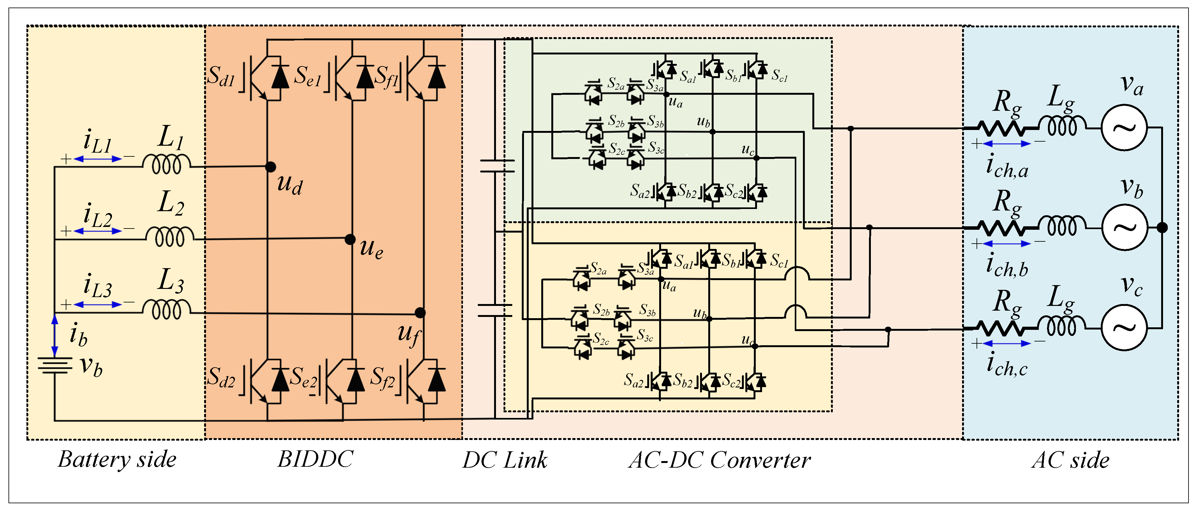
Motivated by the aforementioned limitations, this work presents an enhanced SAPF design that stabilizes the DC-link voltage by combining a dual parallel T-type three-level inverter with an EV-assisted DC–DC converter, as illustrated in
Figure 1 [
24,
25]. The goal of the new design is to maximize the system’s operational dependability, harmonic mitigation, and current-carrying capacity under dynamic circumstances.
An integrated control system architecture is then created by combining the current reference based on SRFs with finite control set model predictive current control (FCS-MPCC) to achieve precise current control. Additionally, because the DC-link voltage is maintained at a constant level, a DC–DC converter managed by a PI regulator is utilized for steady-state compensation [
26].
The MATLAB/Simulink R2023a environment is applied to validate the performance of the proposed system for various operational scenarios, such as nonlinear loads, variable loads, distorted/unbalanced and sag and swell voltage supply conditions. The simulation findings validate harmonic current cancellation, waveform regulation, unity power factor, and steady DC-link voltage [
27].
To the best of the authors’ knowledge, no prior work has combined a dual parallel T-type three-level inverter with an EV-assisted V2G DC-link interface and a hierarchical FCS-MPCC control framework for SAPF applications. The novelty of this work lies in the integrated system architecture, the EV/V2G DC-link support mechanism, and the comprehensive four-scenario validation.
The key contributions of the paper could be stated as follows:
A new double parallel T-type three-level inverter structure for SAPF is proposed in order to increase current capacity and enhance harmonic elimination compared to typical inverter structures.
An EV-based DC–DC converter operating under V2G mode is included in a SAPF structure to provide assistance to the DC bus voltage under variable operational conditions.
Combining the reference current calculation by using the SRF method with FCS-MPCC creates an efficient control strategy to provide adequate current calculations and dynamic behavior.
The effectiveness and applicability of the proposed methodology were investigated using simulation tests for various operational modes such as nonlinearity of load, load variation, and distortion/unbalance.
The remainder of this paper is organized as follows.
Section 2 presents the mathematical modeling of the proposed system.
Section 3 describes the control strategies, including SRF-based reference generation, DC-link voltage regulation, and model predictive current control.
Section 4 provides the simulation-based performance evaluation under different operating scenarios. Finally,
Section 5 concludes the paper and outlines directions for future work.
3. Control Schemes
The control algorithm used in the intended SAPF is presented in this section. The control system’s objective is to provide appropriate DC-link voltage stabilization, current regulation, and harmonic mitigation under various operating situations.
The complete control architecture is organized into three well-coordinated levels that include (i) DC-link voltage control, (ii) reference current generation, and (iii) current tracking control. The control loops work on multiple time scales for optimal performance of the system [
35].
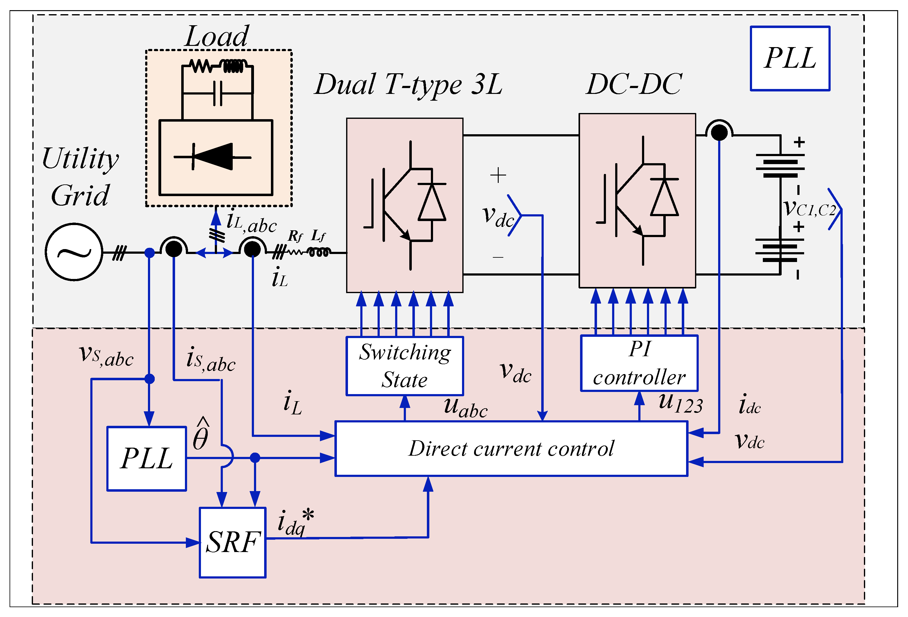
The outer control loop’s role is to regulate the DC-link voltage using an EV-assisted DC–DC converter. In order to separate the fundamental and harmonic components of the current, the second stage uses the SRF technique to calculate the reference compensating currents. The third stage follows the reference currents using FCS-MPCC to determine the inverter’s ideal switching states.
This hierarchical control structure enables fast dynamic response, precise current compensation, and robust operation under a wide range of operating conditions [
8,
36].
3.1. DC-Link Voltage Regulation
Because DC-link voltage regulation controls the quality of the voltage provided by the inverter, it is a crucial parameter for the SAPF to operate efficiently. The current control loop may be impacted by variations in the DC-link voltage, which would reduce harmonic cancellation’s effectiveness.
The EV-assisted DC-to-DC converter will be used in the proposed scheme’s V2G mode to manage the DC-link voltage. In this instance, the EV interface will compensate for the system losses by providing the power input to the DC-link.
The control objective is to maintain the DC-link voltage
at a predefined reference value
[
37]. The voltage error is defined as:
A PI controller is employed to regulate the DC-link voltage and generate the reference active power required to sustain the DC-link energy
where
and
stand for integral and proportional gains, respectively.
The d-axis current reference, or the current that should flow in order to exchange active power between the EV interface and SAPF, is then mapped to this active power reference value [
38].
A proper time scale separation is made possible by the DC-link voltage control’s modest dynamic reaction in comparison to the inner current controller, which ensures stable functioning [
39].
3.2. Reference Current Generation Using SRF Theory
Because it determines how much the harmonics and reactive components need to be adjusted, the compensating reference current is a crucial part of the SAPF process. It is crucial to generate the compensating reference current accurately [
40].
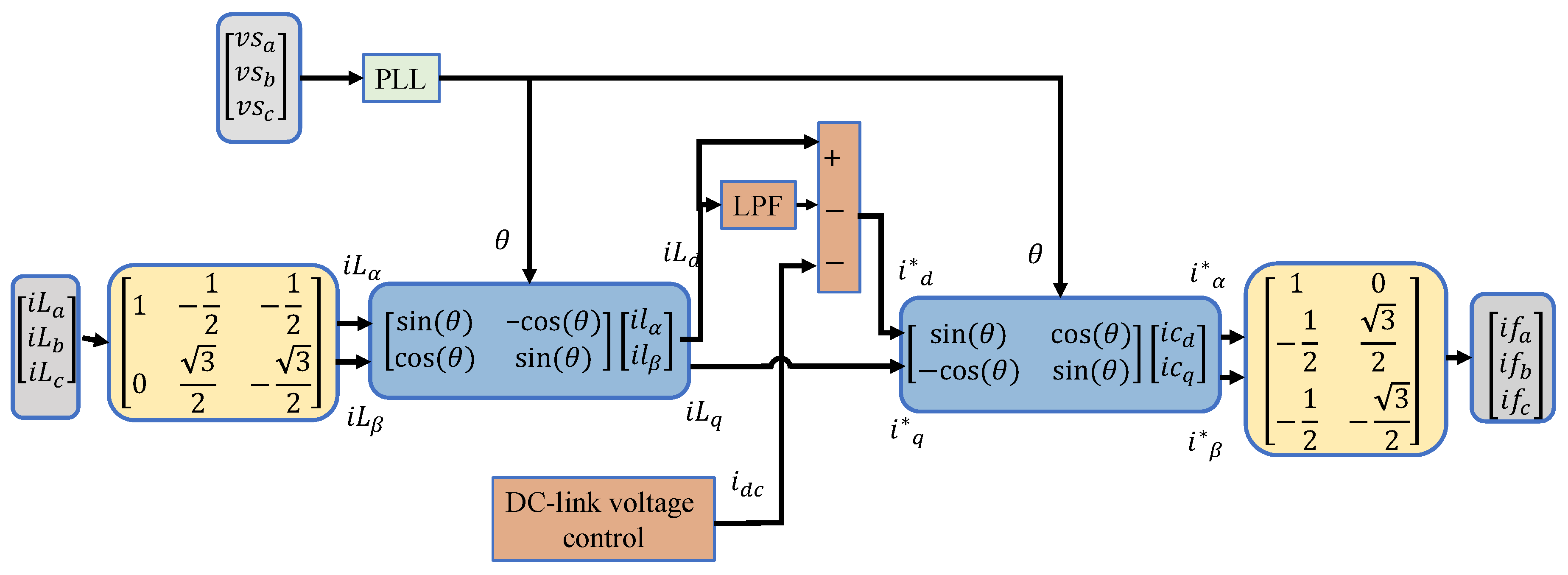
In this work, the SRF method is adopted for reference current generation due to its capability to separate fundamental and harmonic components under both balanced and unbalanced conditions. This method is based on transforming the three-phase quantities from the stationary frame into a rotating reference frame synchronized with the grid voltage [
22].
First, the measured load currents
are transformed into the stationary
frame using the Clarke transformation
Then, the stationary components are transformed into the synchronous
frame using the Park transformation:
where
is the grid voltage angle obtained from a phase-locked loop (PLL).
In the synchronous reference frame, the fundamental components of the load current appear as DC quantities, while the harmonic and unbalanced components appear as oscillatory signals. A low-pass filter (LPF) is therefore used to extract the fundamental components:
The reference compensating currents in the
frame are then defined as:
Finally, the reference compensating currents are transformed back to the three-phase frame to obtain:
This reference current is used by the predictive current controller to ensure accurate tracking and effective harmonic compensation. The complete block diagram of the proposed SRF method [
14] is illustrated in
Figure 5.
3.3. Finite-Control-Set Model Predictive Current Control
The tracking of the reference compensating current is achieved using FCS-MPCC. This control strategy is particularly suitable for SAPF applications due to its fast dynamic response, direct handling of inverter switching states, and ability to operate without a modulation stage [
10].
The predictive control algorithm is based on the discrete-time model of the SAPF derived in
Section 2. At each sampling instant, the future value of the compensating current is predicted for all possible switching states of the inverter. The prediction is performed using the discrete model
where
is the measured current at the current sampling instant, and
is the predicted current for the next sampling step.
Both the future compensatory current and the inverter output voltage for every potential switching state are computed. The error in tracking the estimated current by the reference current is, thus, captured by the cost function, which can be expressed as
where
is the reference current,
is the predicted current corresponding to the
j-th switching state, and
x denotes the phase.
The optimal switching state is selected by minimizing the cost function:
The computational feasibility of the FCS-MPCC algorithm within Ts = 5 µs has been evaluated analytically. For a dual T-type inverter with 27 admissible voltage vectors per inverter and 3 phases, the algorithm evaluates 27 cost function instances per sampling interval. On a modern DSP (e.g., TMS320F28379D at 200 MHz) or FPGA (e.g., Xilinx Zynq-7000), this is achievable: prior studies have demonstrated FCS-MPC execution times below 2 µs on equivalent platforms. This timing budget confirms that the control algorithm itself is not a barrier to real-time implementation; the remaining question, addressed in
Section 4.6, is how closely a physical realization would track the harmonic performance obtained here in simulation.
The inverter then implements the selected switching state for the subsequent sample interval.
Due to the quick and accurate tracking of the reference compensating current, it is guaranteed that the system’s dynamics and harmonic reduction would be much improved by the suggested control approach [
35]. Furthermore, pulse width modulation is not necessary because switching states can be used directly [
21].
3.4. Switching Coordination of Dual T-Type Inverters
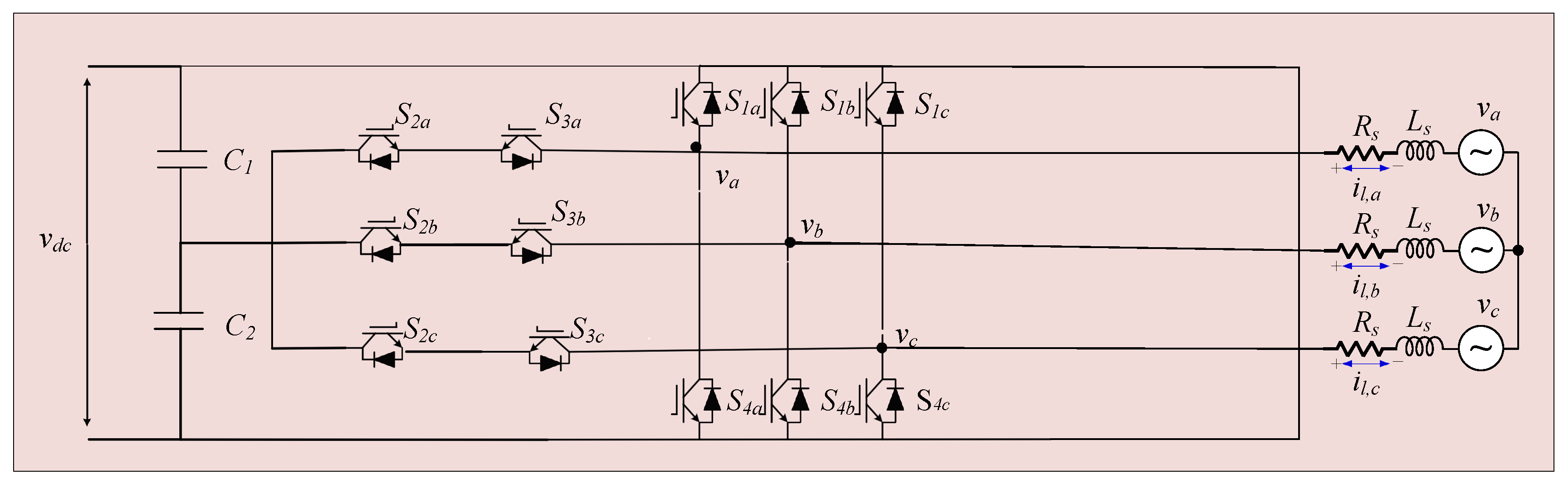
Two T-type three-level inverters connected in parallel are used in the proposed SAPF system to increase current capacity and improve system dependability. For reliable functioning and appropriate compensating current distribution, both inverters must cooperate well.
In this instance, the FCS-MPCC approach enables the two inverters to cooperate automatically. The predictive controller evaluates all potential switching states throughout each sampling period and selects the best state by minimizing the current tracking error. As a result, the switching sequences for both inverters are decided upon at the same time, which naturally results in sufficient operation coordination [
15,
16].
As a result, the two inverters share the compensatory current without requiring a separate active current-sharing control loop such as the master/slave or droop-based regulators commonly used in conventional parallel-inverter architectures, since the FCS-MPCC cost function (Equation (
24)) jointly evaluates switching states for both inverters at every sampling instant and selects the combination that minimizes total current tracking error across both. This is a structural property of the control architecture: current sharing is a byproduct of joint optimization rather than the output of a dedicated regulator.
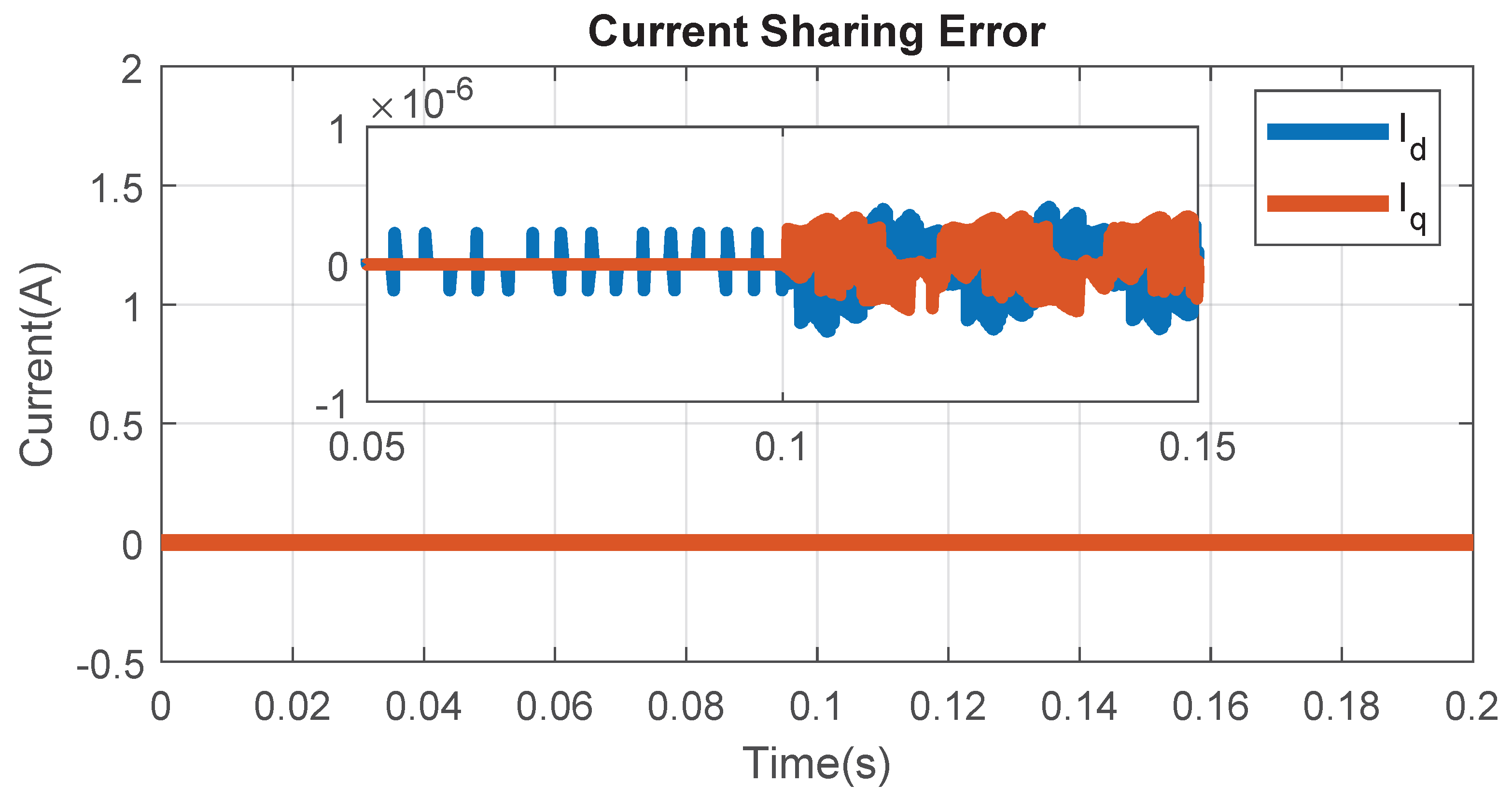
It is important to note that this architectural simplification does not, by itself, guarantee ideal current sharing under real hardware conditions. The near-zero current difference observed in simulation (on the order of A) reflects ideal software conditions with perfectly matched component parameters and zero switching delay. In a physical implementation, device switching asymmetry, parameter tolerances, and propagation delays between the two inverter legs are not captured by the predictive model and can give rise to residual circulating currents that the control algorithm does not directly suppress. Consistent with standard practice for parallel-connected converters, this residual mismatch is addressed passively, through the insertion of small inter-phase inductors (typically 0.5–2 mH), rather than through an additional active control loop. This preserves the algorithmic simplification described above while acknowledging the hardware-level measure needed to bound circulating currents in practice.
4. Simulation and Results
The simulation analysis of the proposed SAPF under various operating conditions is presented in this section. This analysis aims to investigate the effectiveness of the proposed dual parallel T-type inverter design, control method, and EV-based DC-link support system.
With the help of the parameters listed in
Table 1, MATLAB/Simulink R2023a was used to model and simulate the system. In this case, the system is viewed as a low-voltage, three-phase distribution system that serves nonlinear loads. In order to provide compensation currents for harmonic compensation, reactive power compensation, and balancing currents, SAPF is coupled at the PCC. The overall system (
Figure 2) includes the dual parallel T-type three-level inverter, the DC-link supported by the EV-based DC–DC converter operating in V2G mode, and the grid-load interface. The control scheme combines DC-link voltage regulation, SRF-based reference current generation, and FCS-MPCC. To comprehensively evaluate the performance of the proposed SAPF, four representative operating scenarios are considered. Each scenario is designed to assess a specific aspect of system performance, including steady-state harmonic compensation, dynamic response, robustness under distorted and unbalanced conditions, and operation under grid voltage disturbances. The considered scenarios are: (i) SAPF activation under nonlinear loading conditions, (ii) dynamic load variation, (iii) distorted and unbalanced operation, and (iv) grid voltage disturbances including sag and swell conditions. The harmonic performance of the proposed SAPF is evaluated against the requirements of the IEEE 519-2022 standard, which specifies a maximum THD limit of 5% for individual harmonic currents at the point of common coupling in low-voltage distribution systems [
41].
4.1. SAPF Activation Under Nonlinear Load
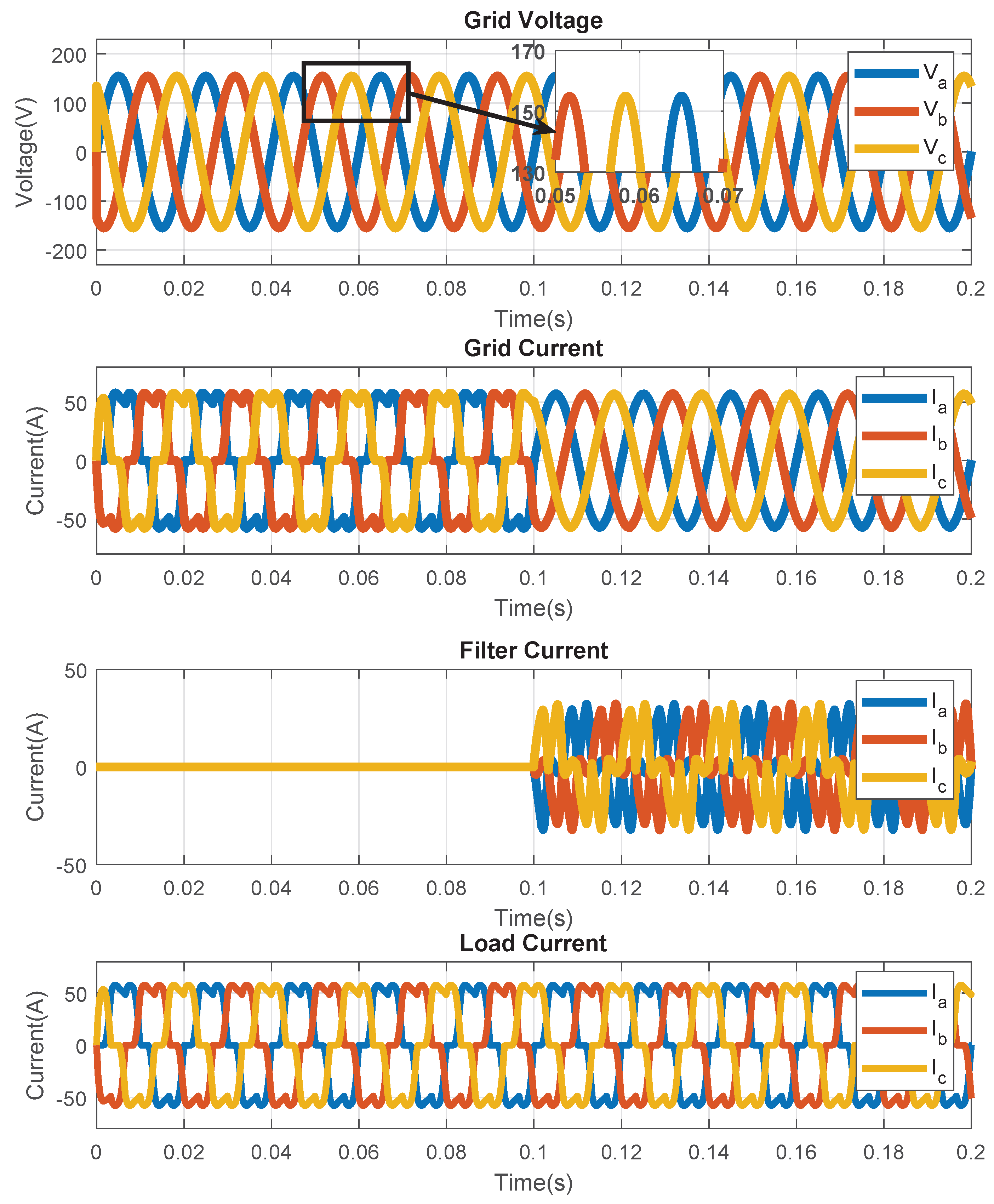
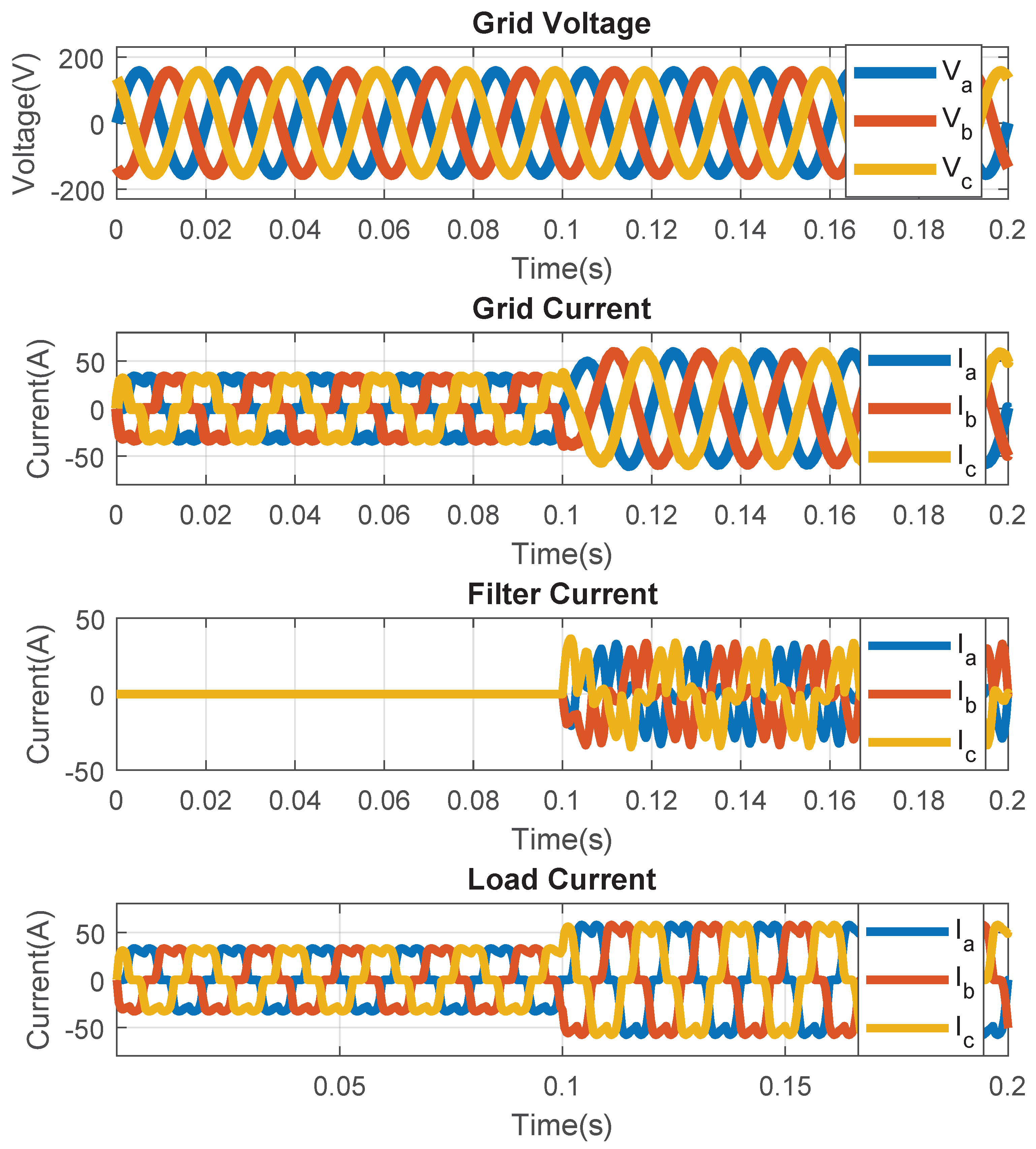
In this scenario, the performance of the proposed SAPF is evaluated under steady-state nonlinear loading conditions. The objective is to demonstrate the effectiveness of the compensation strategy in reducing harmonic distortion and improving the quality of the source current. Initially, the SAPF is deactivated, and the nonlinear load draws distorted currents from the grid. As a result, the source current exhibits significant harmonic distortion and deviates from the sinusoidal waveform. At a specified time instant, the SAPF is activated, and the compensating current is injected into the system.
Figure 4 shows the grid voltage and source current before and after SAPF activation. Due to the nonlinear nature of the load, the source current distortion is extremely significant prior to adjustment. When SAPF is used, the source current becomes almost sinusoidal and synchronized with the grid voltage, indicating a near-unity power factor and appropriate harmonic compensation. The load current and the SAPF compensatory current are shown in
Figure 4. This figure illustrates how the SAPF compensates for the load current distortion by adding the necessary harmonic and reactive currents. The DC-link voltage response is shown in
Figure 6, where it can be seen that the voltage is maintained close to its reference value with minimal fluctuation, confirming the effectiveness of the EV-assisted DC-link regulation.
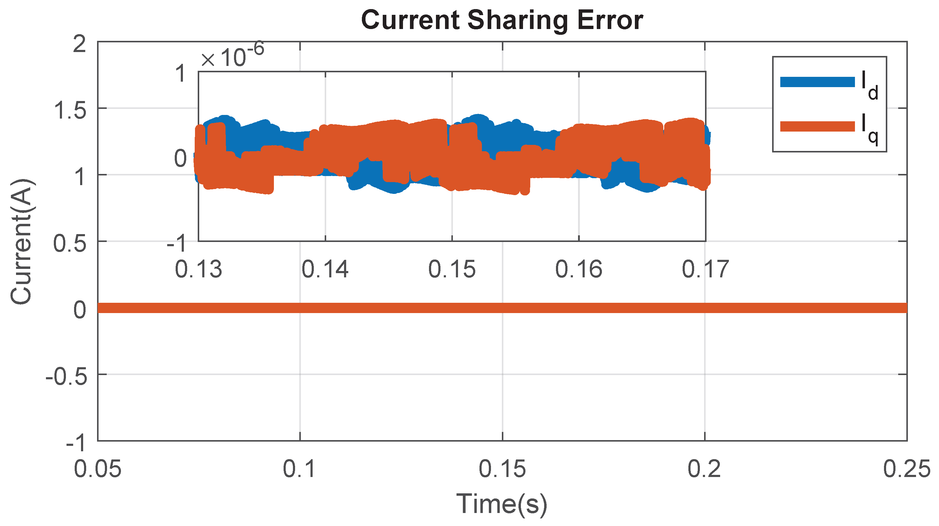
Figure 7 illustrates the phase-wise current difference between the two parallel T-type inverters, defined as
,
, and
. It can be observed that these difference currents remain very small and oscillate around zero, indicating balanced current sharing between the two inverters. This behavior confirms proper coordination of the parallel inverter structure and demonstrates stable operation of the dual-inverter SAPF. The limited magnitude of the current mismatch further indicates that no significant circulating currents are present, which contributes to improved system reliability and performance.
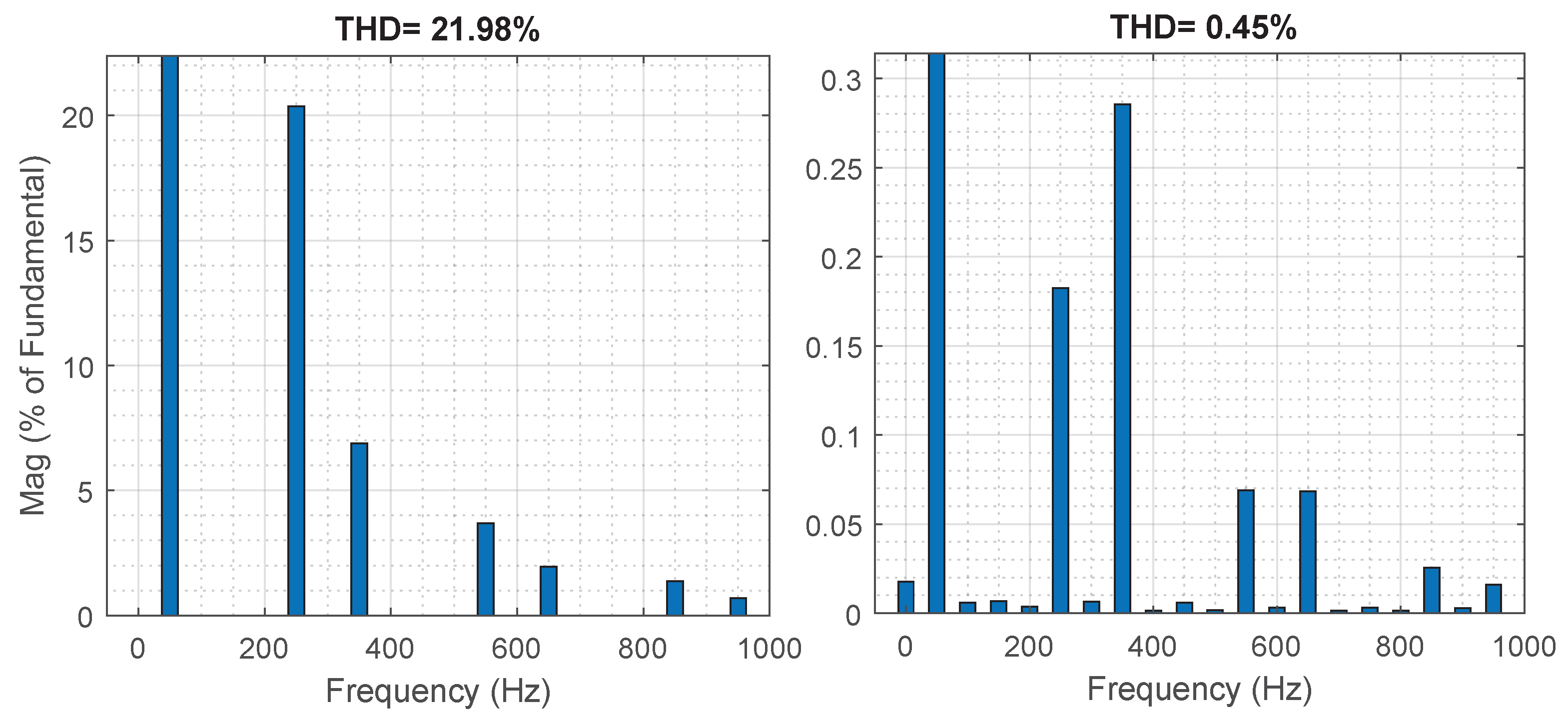
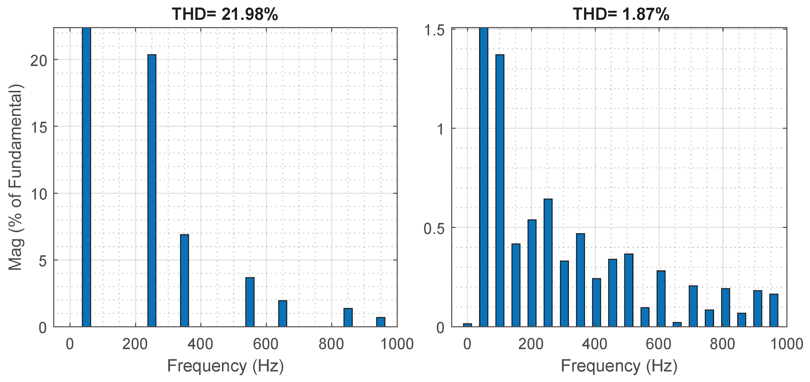
The THD of the source current is significantly reduced after SAPF activation from 21.97% to 0.45%, as shown in
Figure 8, demonstrating the capability of the proposed system to improve power quality under steady-state conditions.
4.2. Dynamic Load Variation
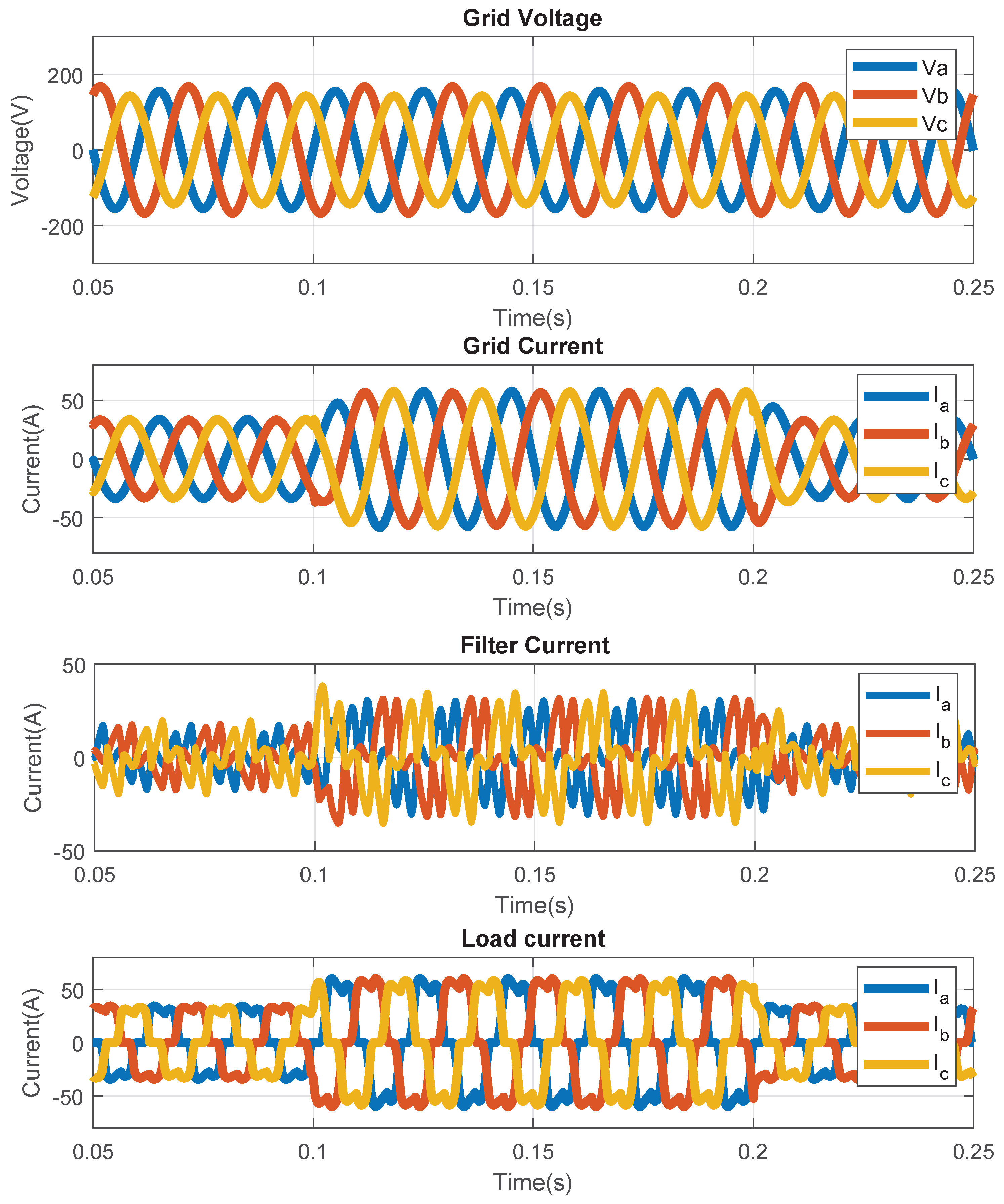
In this scenario, the dynamic performance of the proposed SAPF is evaluated under sudden changes in load conditions. The objective is to assess the ability of the control strategy to maintain effective harmonic compensation and DC-link stability during transient events.
Initially, the system operates under a nonlinear load condition with the SAPF in steady-state operation. At a specified time instant, an additional nonlinear load is introduced, causing a sudden increase in load current and harmonic distortion. This disturbance tests the dynamic response capability of the control system.
Figure 9 shows the grid current, load current, and compensating current during the load transition. It can be observed that the load current increases abruptly at the disturbance instant. In order to maintain a highly sinusoidal grid current with little transient distortion, SAPF responds quickly by adjusting the compensating current.
Figure 10 illustrates the DC-link voltage behavior during load variation. This graphic illustrates how the DC-link voltage can be kept constant in relation to the reference voltage even when the load state abruptly changes.
The absence of any harmonics in the grid current both before and after the disturbance demonstrates the efficacy of the chosen control strategy.
Figure 11 illustrates the phase current difference between the two parallel-connected T-type inverters in order to examine the efficacy of a dual inverter system.
,
, and
represent this.
It is evident that the current is distributed equally across the two inverters because the difference current values are very modest and swing about zero. It indicates that the parallel inverter setup is properly coordinated, and as a result, the SAPF is operating steadily with no circulating currents.
4.3. Distorted and Unbalanced Conditions
In this instance, the system’s distortion and imbalance are examined in relation to the suggested SAPF’s performance. Testing the controller’s ability to provide sufficient harmonic cancellation and current balance in a non-optimal scenario is the aim here.
These imbalances and distortions are created by adding imbalances and distortions to the system, which results in harmonic content and uneven phase currents. This is a representation of actual distribution system scenarios.
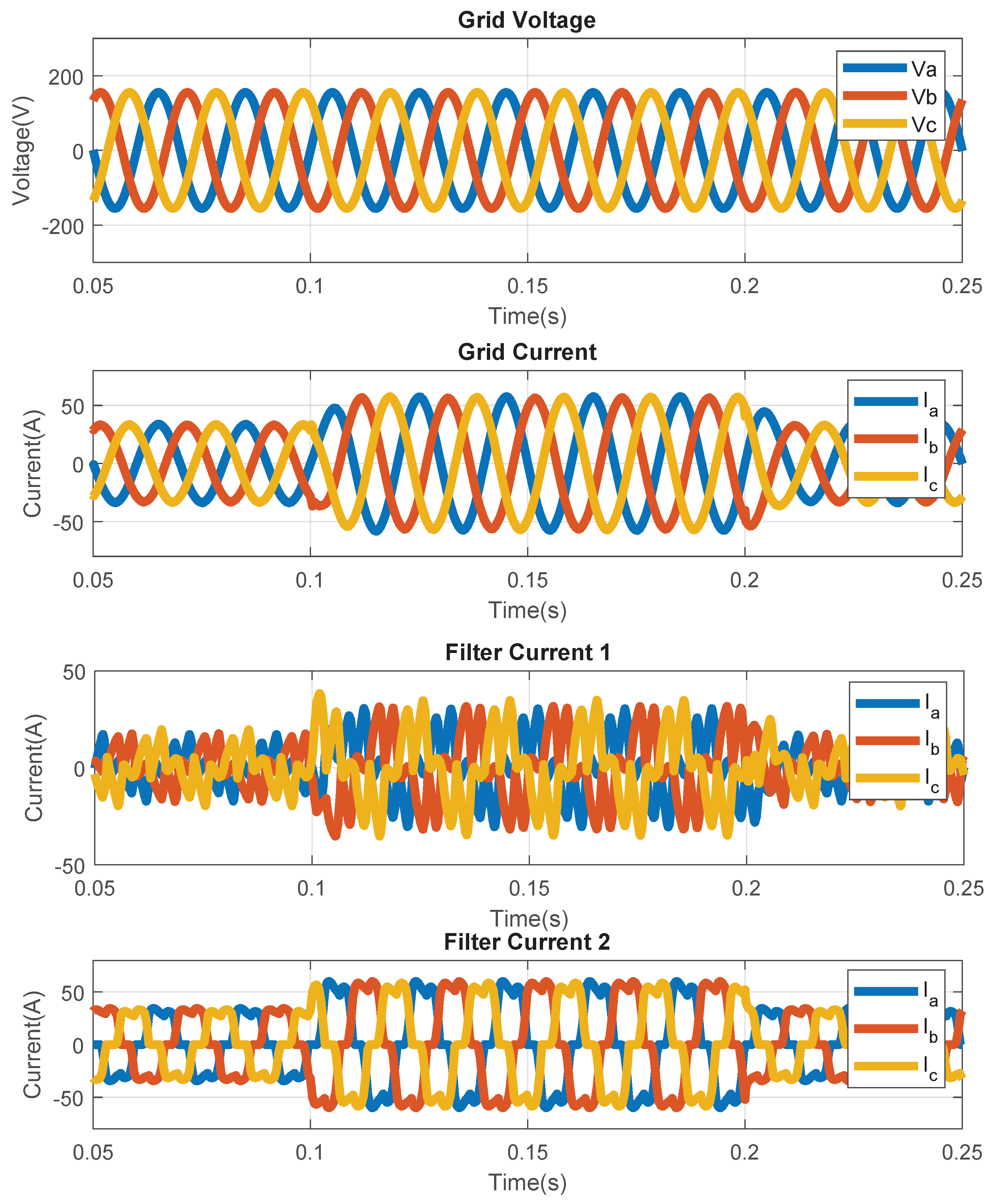
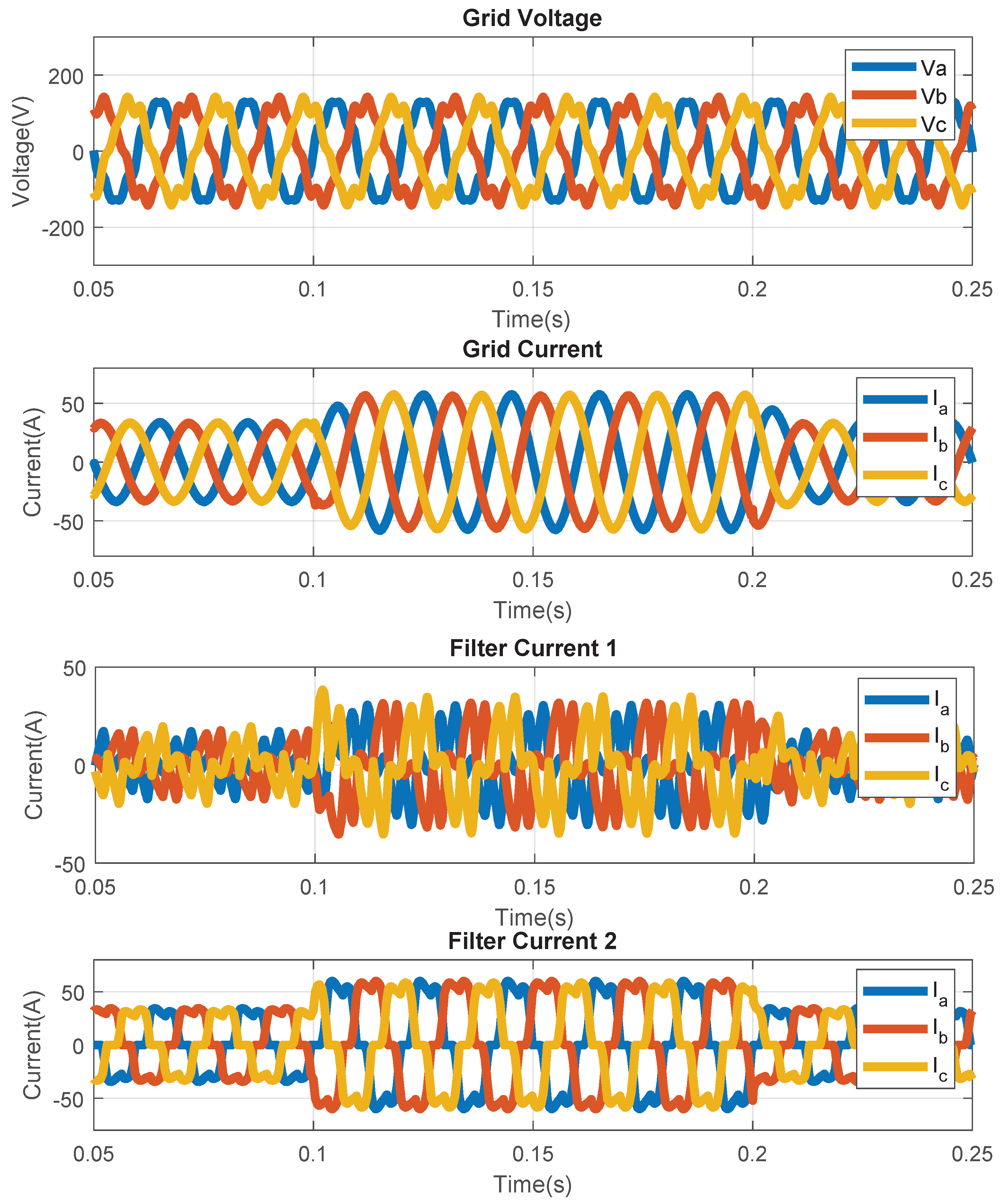
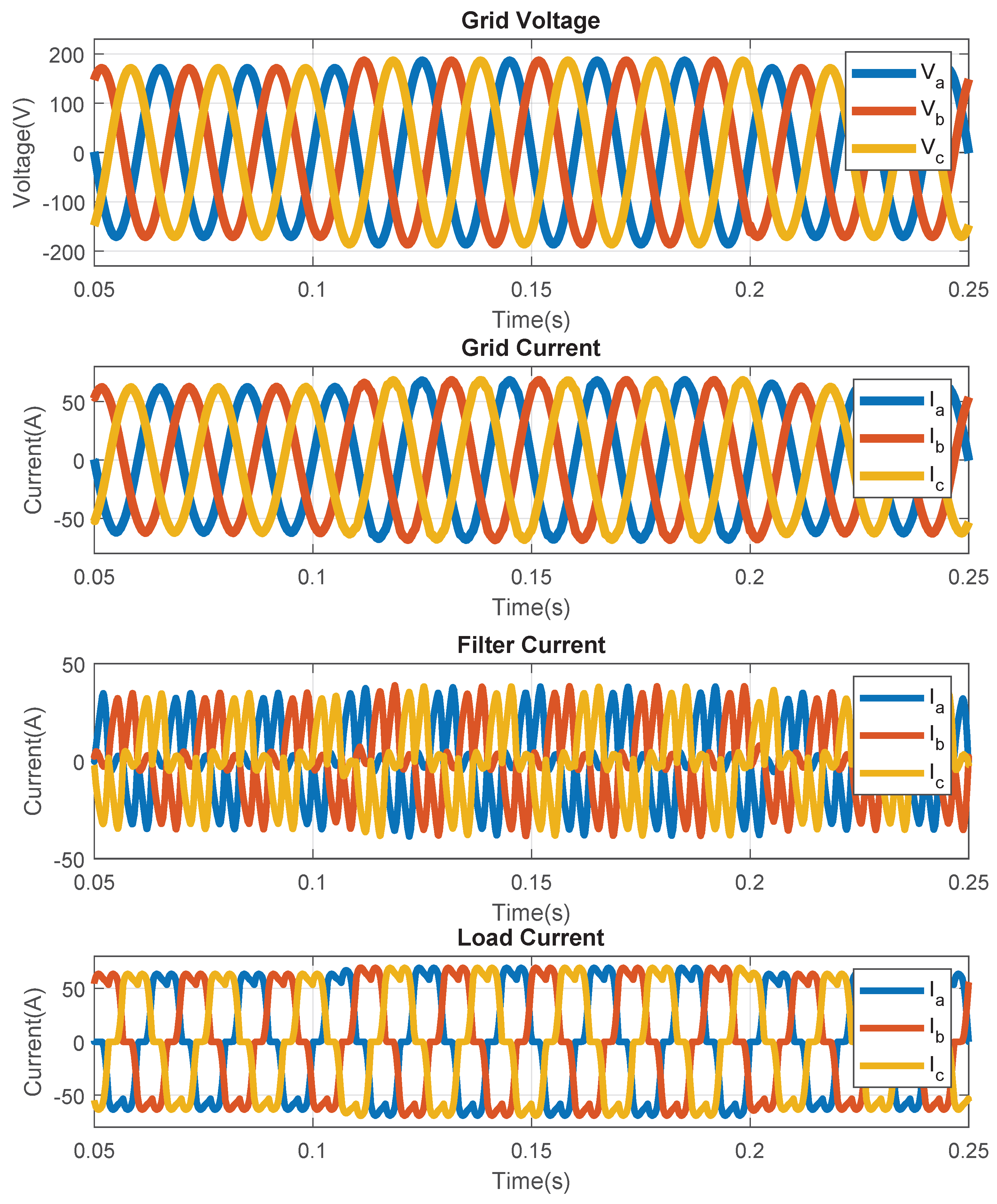
The grid voltage, grid current, SAPF compensatory current, and load current waveforms for both distorted and unbalanced situations are shown in
Figure 12 and
Figure 13 respectively. The SAPF supplies the compensating current so that the grid current is almost sinusoidal and balanced, despite the distorted and unbalanced load current waveform seen in the figures.
These results demonstrate that even in the face of distortions and imbalances, the suggested controller can provide stability, harmonic compensation, and current balance.
The SAPF is activated to compensate both harmonic and unbalanced current components.
4.4. Voltage Sag Condition
In this scenario, a voltage sag is introduced by reducing the grid voltage magnitude within a specified time interval. This condition simulates grid faults or sudden load increases.
Figure 14 shows the grid voltage, load current, SAPF compensating current, and resulting grid current during the voltage sag event. It can be observed that, despite the reduction in grid voltage magnitude, the SAPF maintains the grid current nearly sinusoidal and well controlled.
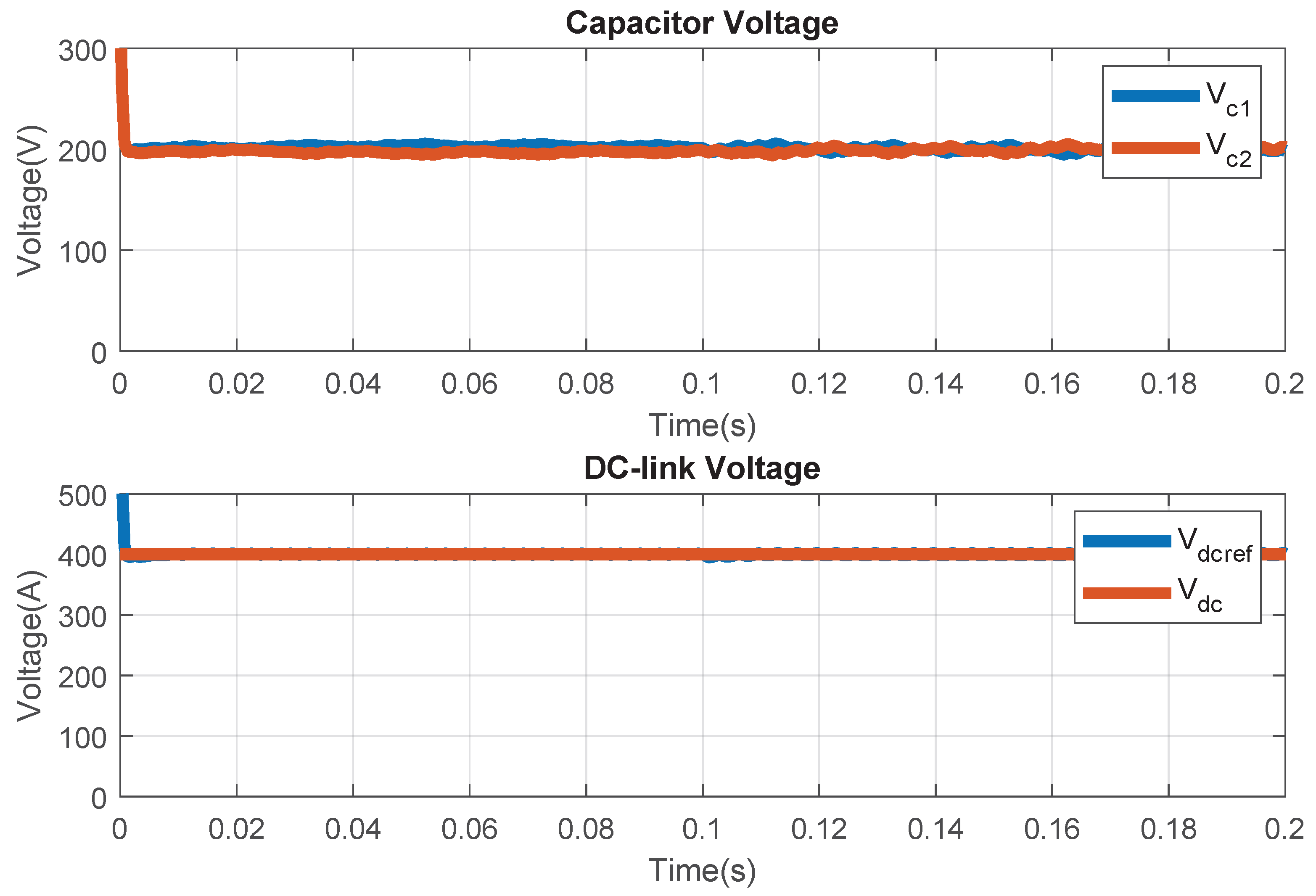
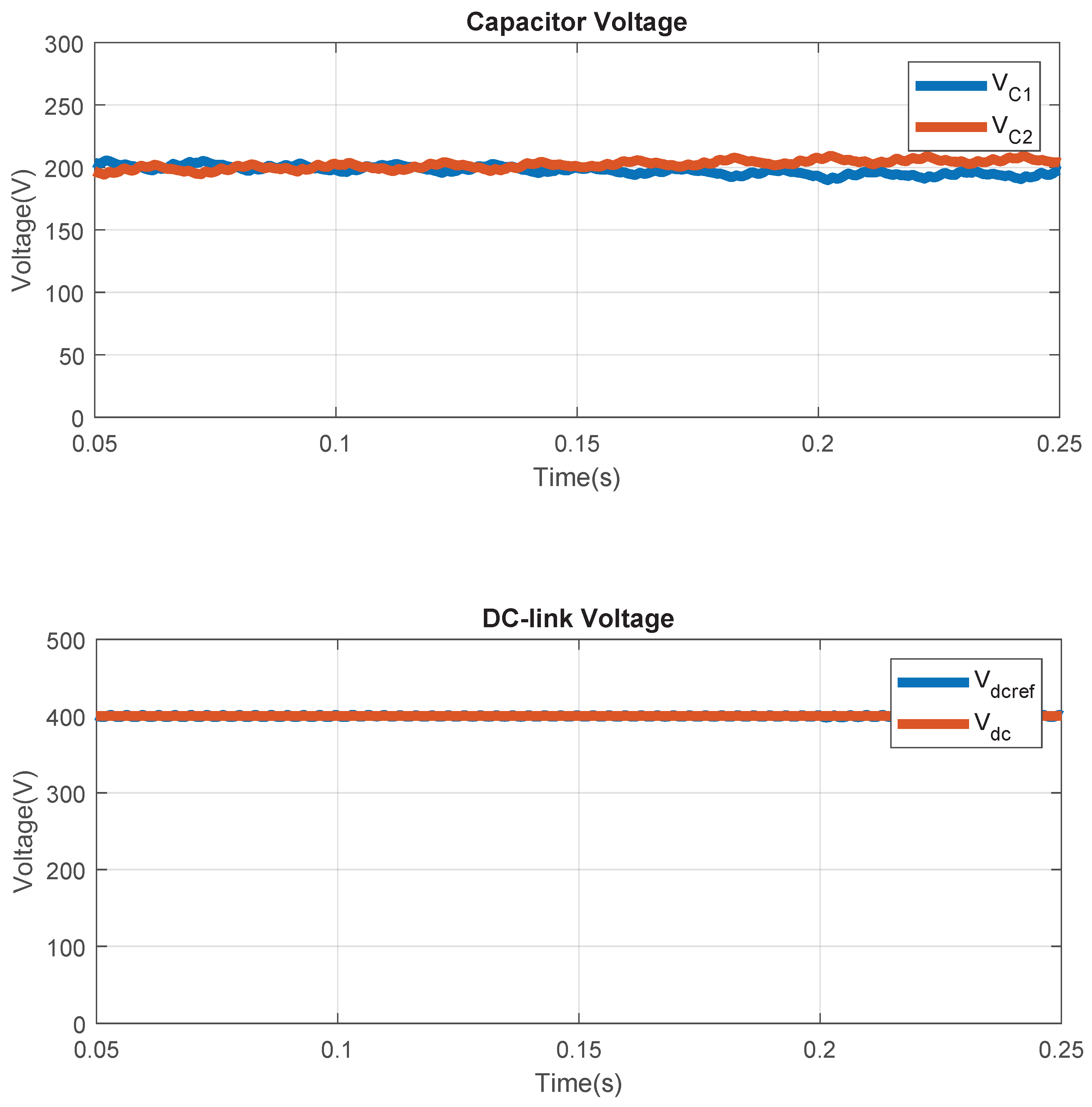
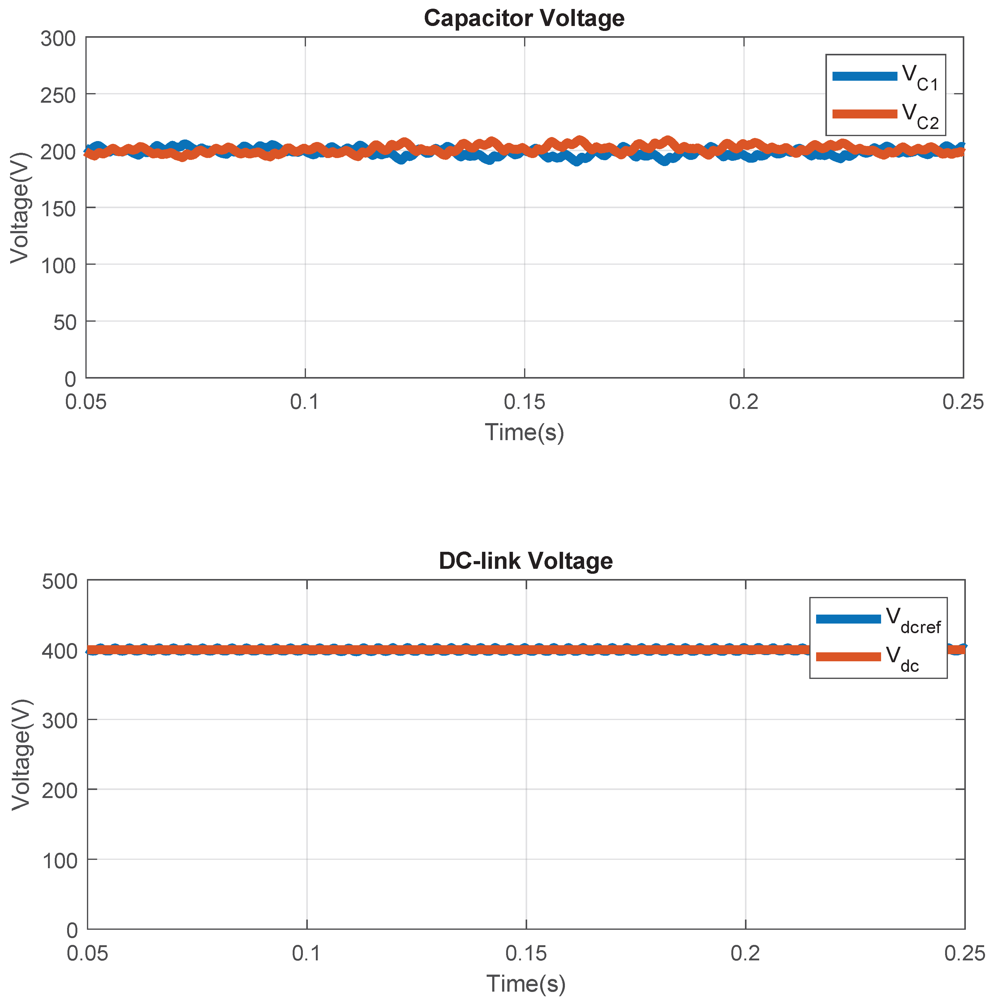
Figure 15 presents the DC-link capacitor voltages,
and
, and the total DC-link voltage,
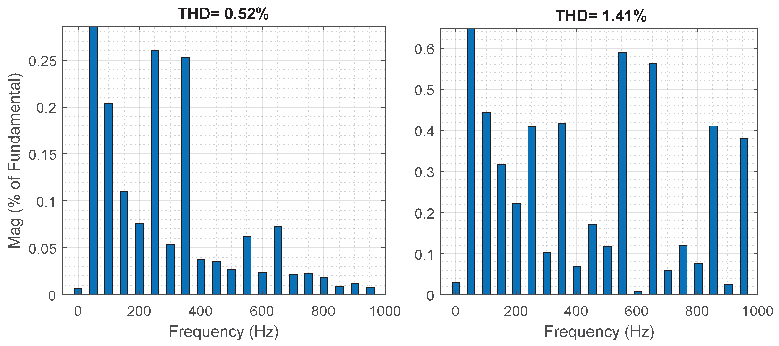
. With a few minor transient fluctuations, the voltage at the DC connection is likewise found to be around the reference value, demonstrating appropriate energy management during sag conditions. Furthermore, even in the case of voltage sag, the harmonics analysis (
Figure 16) demonstrates that the THD of the source current is significantly reduced.
This demonstrates that the proposed control strategy will offer appropriate and consistent performance as well as harmonic compensation during voltage sags.
4.5. Voltage Swell Condition
In this instance, the voltage swell is produced by changing the grid’s voltage magnitude over the designated time frame. This overvoltage condition may be brought on by a load disconnect or grid issues.
The voltages and currents at several circuit places where a voltage swell occurs are depicted in
Figure 17. The figure shows that there is no issue with the grid current despite an increase in the grid voltage magnitude.
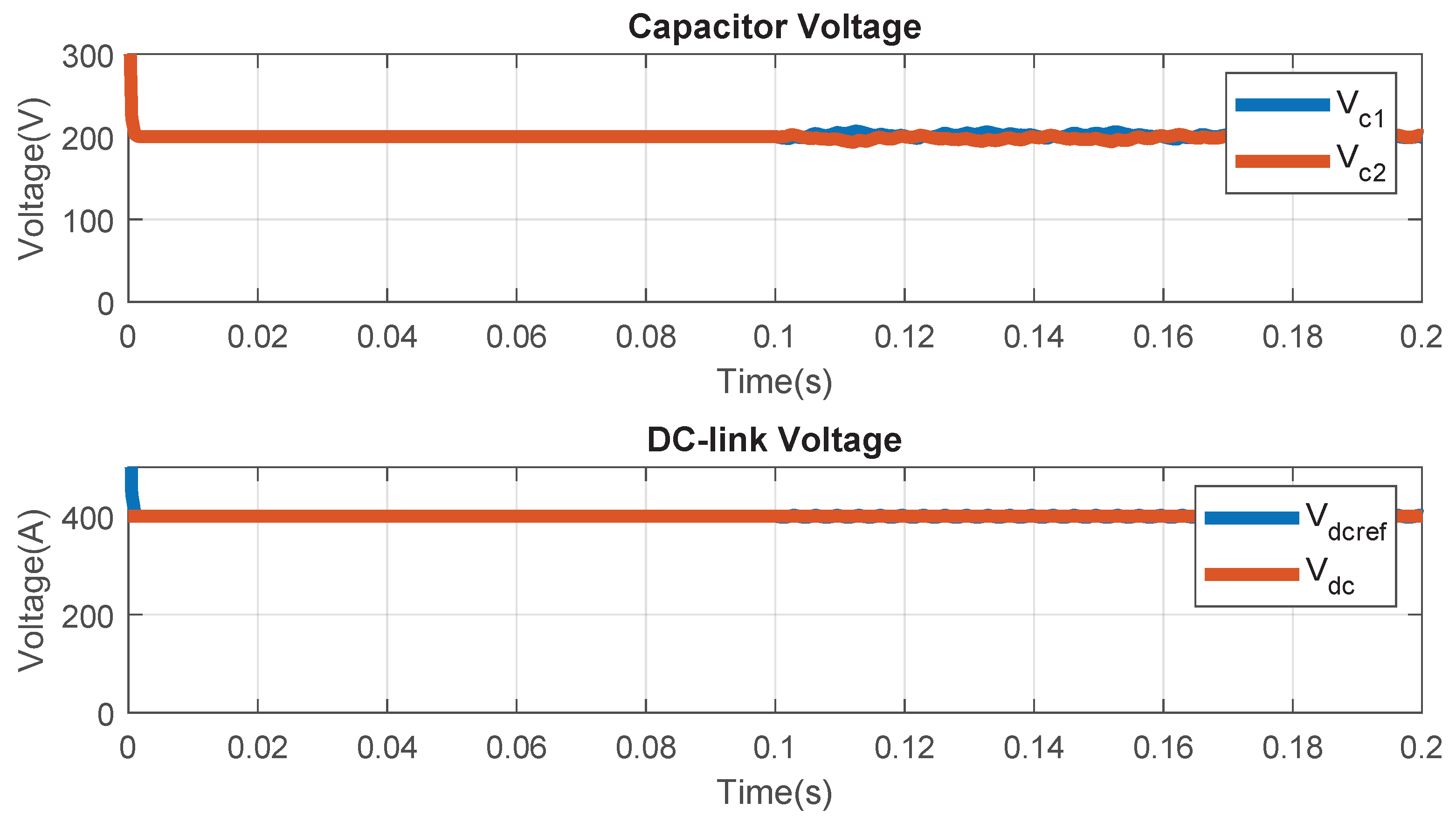
The DC-link capacitor voltages
and
and the DC-link voltage
are displayed in
Figure 18. The system appears to be functioning steadily under the swell condition since the DC-link voltage is adequately controlled, and the capacitor voltages are balanced.
This makes it abundantly evident that the suggested SAPF functions effectively even in the presence of the disturbance voltage swell.
Furthermore, as
Figure 18 illustrates, the DC-link voltage is highly controlled around its reference value of
. The success of the DC-link control technique based on PI controllers is demonstrated by the relatively little ripples that occur during the disturbance. The equal capacitor voltages
and
demonstrate the uniform distribution of energy.
Additionally, even in the case of voltage swell, the harmonics analysis (
Figure 19) shows that the THD of the source current is well minimized.
These results unequivocally demonstrate that the twin T-type inverter-based SAPF system’s novel architecture functions well in situations of grid voltage swell.
4.6. Harmonic Distortion Analysis
The generated SAPF’s performance can be further evaluated by using the FFT technique to analyze the signal’s harmonics. The source current spectrum before and after correction is shown in
Figure 8.
Table 2 summarizes the overall performance of the proposed SAPF across the different operating scenarios considered in this study, including nonlinear, dynamic, and unbalanced loads as well as voltage sag and swell conditions, confirming consistently low THD, near-unity power factor, and stable DC-link behavior throughout.
Because of the nonlinear loads, the load current is severely distorted before the SAPF is applied. The source current’s THD is approximately , and the harmonics are primarily of low order, such as the fifth and seventh harmonics.
The level of harmonics is significantly decreased by using the created SAPF. THD’s value falls to .
Furthermore, the near-perfect operating power factor performance is achieved by compensating the source current, which produces nearly sinusoidal behavior in harmony with the grid voltage.
Even under nonlinear loads, the measured THD value conforms with the IEEE-519-2022 standard values for low voltage distribution networks [
41], confirming the efficacy of the proposed SAPF in enhancing power quality.
Having established in
Section 3.3 that the FCS-MPCC algorithm is computationally realizable within the
sampling window, it is equally important to assess how the reported THD figures would translate to a physical system. The 0.45% value obtained here reflects idealized simulation conditions: noise-free current sensing, perfectly matched filter parameters between the two parallel inverters, and switching-state selection with no additional dead-time or measurement delay beyond the timing budget confirmed above. In practice, current sensor noise and quantization, dead-time, and parameter tolerances between the paralleled inverter branches would introduce additional distortion beyond what an idealized model captures. This is consistent with the broader FCS-MPC-based SAPF literature: MPC-based SAPFs with formal stability guarantees have reduced comparable pre-compensation THD levels to values validated through hardware-in-the-loop testing, SRF-based MPC controllers validated on experimental converters have achieved THD as low as roughly 3%, and controller-hardware-in-the-loop evaluations across various nonlinear load types have consistently reduced double-digit THD to values below 3%. A physical realization of the proposed system is therefore expected to achieve THD in a comparable 1–3% range, still well within the IEEE-519-2022 limit of 5%, though higher than the idealized 0.45% simulation figure. Together with the timing analysis in
Section 3.3, this indicates that both the real-time computational requirements and the harmonic compensation performance of the proposed SAPF are expected to hold on physical hardware; formal confirmation of both aspects through DSP/FPGA implementation and HIL testing is identified as the immediate next step for this work (
Section 5).
4.7. Comparative Analysis: FCS-MPCC
Versus Sliding Mode Control
To further validate the superiority of the proposed FCS-MPCC strategy, a comparative evaluation is conducted against a Sliding Mode Control (SMC) scheme applied to the same dual parallel T-type SAPF configuration under identical operating conditions (Scenario 1: fixed nonlinear load, same system parameters as listed in
Table 1).
4.7.1. SAPF Activation Response Under
Sliding Mode Control
Figure 20 presents the source current waveforms under the SMC strategy following SAPF activation. After activation, the source current exhibits a transient settling period before reaching steady state. During this transient phase, a noticeable residual ripple is observed, which is attributed to the inherent chattering phenomenon associated with sliding mode controllers. This chattering arises from the high-frequency switching around the sliding surface, causing the system trajectory to oscillate rather than converge smoothly. In steady state, the source current approaches a near-sinusoidal waveform, demonstrating the capability of the SMC to achieve harmonic compensation under fixed nonlinear load conditions.
4.7.2. Harmonic Distortion Analysis
Under Sliding Mode Control (SMC)
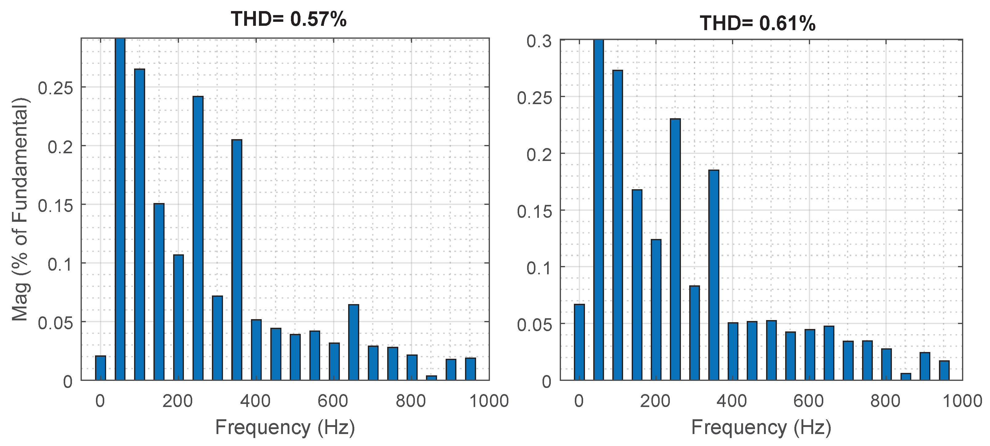
The FFT spectrum of the source current after SAPF activation under the SMC strategy is presented in
Figure 21. Before compensation, the source current THD is approximately
, dominated by low-order harmonic components, particularly the 5th (250 Hz) and 7th (350 Hz) harmonics. After SAPF activation with the SMC controller, the THD is reduced to approximately
. The quantitative harmonic performance of the SMC-based SAPF is summarized in
Table 3.
4.7.3. Discussion
The comparative results in
Table 3 highlight several trade-offs between the proposed FCS-MPCC strategy and the SMC approach:
- 1.
Lower THD: FCS-MPCC achieves a post-compensation THD of 0.45%, compared to 1.87% under SMC. This suggests that the online cost-function optimization performed at each enables more precise tracking of the reference compensating current than the fixed switching surface of SMC.
- 2.
Reduced current ripple: As visible in the filter current waveforms of
Figure 20, the FCS-MPCC-compensated current exhibits a smoother profile than the SMC-compensated current, consistent with the chattering phenomenon commonly reported for SMC strategies operating near the sliding surface [
42], which is a known source of additional harmonic content and increased switching device stress.
- 3.
Fixed switching frequency: SMC in its conventional form typically operates at a variable switching frequency [
42], which complicates filter design and increases electromagnetic interference (EMI). FCS-MPCC operates at a fixed sampling frequency of 200 kHz, simplifying harmonic analysis and filter design.
- 4.
Comparable dynamic response: Both strategies exhibit similar settling times (≈20 ms,
Table 3), indicating that the two approaches provide comparable transient response during SAPF activation and load changes under the tested conditions.
- 5.
No modulation stage required: Both strategies operate without a PWM modulator. FCS-MPCC directly selects the optimal switching state from the finite control set, eliminating the need for sliding-surface design and gain tuning, which are known to be sensitive to system parameter variations in SMC, at the cost of a moderately higher per-cycle computational burden.
These results indicate that the proposed FCS-MPCC strategy offers improved harmonic compensation and steady-state current quality, and reduced parameter sensitivity, compared to the SMC approach under identical topology and load conditions, while both strategies achieve compliance with the IEEE 519-2022 harmonic standard [
41].
4.8. Summary of Practical Implementation Considerations
While the simulation results confirm the effectiveness of the proposed control strategy, several practical factors affect the transition from simulation to hardware implementation. Six such factors are summarized below, several of which have already been discussed in the relevant sections above.
Computational burden. As shown in
Section 3.3, the FCS-MPCC algorithm evaluates 27 cost-function instances per sampling interval (
). Prior studies report FCS-MPC execution times below 2
on comparable DSP/FPGA platforms, indicating this is achievable, though formal timing verification on the target hardware remains future work.
Dead-time effects. T-type inverters require a dead-time interval between complementary switch transitions to prevent shoot-through across the DC-link. Typical dead-time values for IGBT-based T-type legs are on the order of 1–2
. Dead-time introduces a voltage error at each switching transition that is proportional to the dead-time duration and switching frequency, and it is a well-known source of low-order current harmonics and zero-current-crossing distortion in VSI-based SAPFs. This effect is not modeled in the present simulation and is expected to be a contributor to the gap between the simulated 0.45% THD and the hardware-realistic 1–3% range discussed in
Section 4.6.
Parameter uncertainty. The predictive model (Equation (
23)) assumes exact knowledge of
and
. In practice, filter inductor tolerances (typically ±5–10%) and mismatch between the two parallel inverter branches would introduce prediction error in the FCS-MPCC cost function and, as noted in
Section 3.4, could give rise to small circulating currents between the two inverters that the idealized simulation (with perfectly matched parameters) does not capture. Mitigation typically takes the form of small inter-phase inductors (0.5–2 mH, as discussed in
Section 3.4), a passive hardware measure that does not require an additional active current-sharing controller, consistent with the architectural simplification the FCS-MPCC provides. An online parameter estimator is a candidate active-control extension for future work, should passive mitigation prove insufficient.
Measurement delay. The predictive control law in
Section 3.3 assumes the measured current
is available instantaneously at the start of each sampling interval. In practice, ADC conversion and signal-conditioning introduce a finite delay, commonly addressed in the FCS-MPC literature through one-step-ahead delay compensation (predicting
from
rather than directly applying the switching state computed from
). This delay-compensation extension was not implemented in the present model and is recommended for the hardware implementation phase.
Switching losses. Because FCS-MPCC does not enforce a fixed carrier-based switching pattern, its effective switching frequency varies with operating conditions but is bounded by the 200 kHz sampling frequency. T-type three-level inverters are reported in the literature to exhibit lower switching losses than equivalent two-level inverters at comparable voltage and current ratings, owing to the reduced voltage step (
rather than
) across each commutation. Reported efficiencies for T-type inverters in comparable power ranges are typically in the 97–99% range. Combined with the conduction loss estimate already given in
Section 2.1.2 (≈45 W per phase, or ≈1.35% of rated power), total semiconductor losses for the proposed dual-inverter configuration are expected to remain within a similar single-digit percentage of rated power, though a full datasheet-based loss calculation for the selected switching devices has not been performed and is left for future work.
Thermal performance. The parallel configuration distributes the total compensating current across two sets of semiconductor devices rather than one, which is expected to roughly halve the current stress, and consequently the conduction and switching loss, per device relative to a single-inverter SAPF of equivalent rating. This is consistent with the reliability and thermal-distribution motivation stated in the Introduction. However, junction temperature rise depends on device-specific thermal resistance and heatsink design, which have not been modeled here. A formal electro-thermal simulation (e.g., using PLECS or a datasheet-based thermal network) is identified as a necessary step prior to hardware prototyping.
5. Conclusions
This study describes an enhanced three-phase SAPF that uses a dual parallel T-Type three-level inverter topology to improve power quality in low-voltage distribution systems. The suggested system makes use of the SRF methodology to extract reference current, the FCS-MPC approach for current tracking, and the PI controller for DC-link voltage management. The thorough simulation study has taken into account four scenarios: activation filter, fixed and variable load, distorted and unbalanced load, and sag and swell voltage. The simulation results make it abundantly evident that the suggested SAPF successfully lowers the current’s harmonics, balances the source current, and regulates the DC-link voltage in every scenario. According to IEEE-519-2022 regulations, the source current THD is decreased in the situation of distorted grid voltage.
The T-type with two inverters provides better current handling capacity and more effective harmonic suppression than the traditional SAPF with one inverter. Additionally, the usage of FCS-MPC enables effective system operation and quick dynamic reaction because it does not require multi-loop algorithms for PWM generation.
Future study will focus on improving the suggested controller to reduce switching and computing work. Alternative DSP/FPGA controller designs will also be investigated. Moreover, there will be a focus on experimental implementation using a TMS320F28379D DSP or Xilinx Zynq-7000 FPGA, combined with HIL validation using dSPACE or OPAL-RT. The prototype will incorporate = 0.1 , inter-phase inductors, and dead-time compensation.





 ,
,