Article

Thermal Stabilization as a Key to Sustainable Operation of Combustion Engines and Power Plants—Part 2: Thermal Stabilization of IES Due to Advanced Intake Air Cooling and Heat Recovery Assessed by Appropriate Criteria

1
School of Naval Architecture & Intelligent Manufacturing, Jiangsu Maritime Institute, Gezhi Road 309, Nanjing 211170, China
2
Admiral Makarov National University of Shipbuilding, Heroes of Ukraine Avenue 9, 54025 Mykolaiv, Ukraine
3
Yangzhou COSCO Shipping Heavy Industry Co., Ltd., Yingzhou Road No. 1, Jiangdu Yanjiang Development Zone, Yangzhou 225200, China
*
Author to whom correspondence should be addressed.
Energies 2026, 19(17), 4221; https://doi.org/10.3390/en19174221
Submission received: 1 July 2026 / Revised: 9 August 2026 / Accepted: 13 August 2026 / Published: 7 September 2026

Abstract

The sustainable performance of combustion engines in integrated energy systems (IESs) at a safe thermal level and with high fuel effectiveness is possible if intake air is cooled and the released heat is fully utilized by a heat recovery chiller (HRCh). Herein, the temperature of return hot water, used as a coolant, at the engine inlet is not to be higher than 70 °C to ensure safe, thermally stabilized engine performance. This cannot be ensured by only an absorption lithium-bromide chiller (LBCh) as the most efficient HRCh, which has a COP of about 0.7 and provides a return hot-water temperature of about 75 °C against the required 70 °C, which reduces the engine lifetime by about 10%. To ensure the thermally stabilized performance of the engine in conventional IESs, the residual heat left from the LBCh is ejected into the atmosphere by an emergency radiator with a heat loss of about 25% as the “cost” for safe engine performance. The concept of IES thermal stabilization in terms of both aspects—intake air cooling and the full utilization of the released heat by a combined LBCh boosted by an ejector chiller (ECh), easily implemented into an existing IES—was developed. The appropriate new unified criterion indicators for estimating the rate of thermal stabilization (RS) were adopted to ensure sustainable performance and increased the lifetime of the engine by about 10%, providing an innovative heat recovery intake air cooling system and boosting the conventional IES as a prosperous trend. Thus, for the first time in the practices of IES design and operation, the aggregated effect on engine thermal stabilization, followed by maximizing its efficiency, has been gained due to intake air cooling and full utilization of the heat released as mutually affecting aspects.

1. Introduction

Integrated energy systems (IESs) [1,2] are aimed at the combined production of electrical/mechanical power, heat and cold, in addition to the heat and power inherent in cogeneration or combined heat and power (CHP) plants [3,4]. They are generally manufactured with heat exchangers for extracting heat from lubricating oil, the engine jacket, charge air and exhaust gas to provide a hot-water temperature of about 90 °C or steam [5,6]. The hot water or steam meets thermal demands in CHP and is converted to refrigeration by heat recovery chillers (HRChs) in CCHP plants [7,8].
The cold produced in trigeneration plants is generally applied for outside consumption: food industries and other industrial needs [9,10] and space air conditioning [11,12]. They are widespread in buildings [13,14] and stationary and transport applications [15,16]. The yearly performance of these plants is associated with varying loads [17,18], which need different coolants and the application of efficient heat exchangers [19,20] to ensure their operation with a high heat flux within a wide range of load changes.
Internal combustion engines (ICEs) [21,22], gas engines (GEs) [23,24] and gas turbines [25,26] have a widened application as prime movers in IES of the trigeneration type.
Their effectiveness is strongly affected by the intake air temperature and drops if it increases [27,28]. Therefore, its cooling provides engine performance with high fuel efficiency due to reduced specific fuel consumption (SFC) [29,30].
If cold is spent on cooling engine cyclic air to increase fuel and overall efficiency, so-called in-cycle trigeneration takes place [31,32]. Engine cyclic air cooling makes it possible to nearly double the duration of IES efficient operation, when outer cooling needs are decreased or absent.
CCHP plants with cooling cyclic air have high flexibility because they match the actual loads upon driving engines [33,34] according to electrical, heat and cold demands [35,36] under variable parameters of intake air according to the site’s climate.
Engine intake air cooling can be provided by transforming the heat removed into cooling capacity by heat recovery chillers (HRChs) [37,38].
The reserve for improving engine thermal stabilization through increasing the efficiency of cooling intake air depends on the heat removed [39,40] and the effectiveness of its transformation into cooling capacity, estimated by the COP as the cooling capacity gained related to the heat spent.
In the case of ICEs as the prime movers combusting fossil fuels, the heat released might be increased due to the application of exhaust boilers with condensing surfaces [41,42], which allow for lowering the temperatures of exhaust gas, i.e., to increase the heat utilized, and provide the easy extraction of contaminations, enabling a decrease in corrosion [43,44] and pollution into the environment. Furthermore, the increased heat being transformed into cold enables deep intake air cooling and provides thermally stable engine operation while applying the HRCh, even with a lower COP.
The heat released from engines can be transformed into cooling intake air by different HRChs [45,46]. Lithium-bromide-type absorption chillers (AChs) are the most widespread and produce chilled water of about 7 °C by converting the heat of hot water at about 90 °C with a COP of about 0.7 [47,48]. Herein, the temperatures of cooled intake air are limited to 15 °C.
Jet apparatuses such as thermopressors [49] and ejector chillers (EChs) [50] generally include heat exchangers, easily integrated into existing power plants. Herein, the EChs are able to cool air to 10 °C and lower to produce an enhanced effect but at a decreased COP [51,52]. Moreover, the EChs are very sensitive to changeable thermal loads [53,54], which causes a drop in the COP. They require pre-cooling air, for instance, by vapor compression machines (VCMs) [55,56] or AChs [57,58], to compensate for load fluctuations, which would ensure a stabilized load on EChs.
A wide range of exhaust temperature differences might be covered by stage [59,60] or cascade [61] transformation. The stage combination of AChs and EChs [62,63] provides deeper cooling air due to the application of hybrid coolants in air coolers: water and refrigerant [64].
The cascade configuration [65] enables the involvement of the heat potential over a wider range through hybrid cooling [66], inaccessible for one-stage heat transformation by AChs.
An enhancement in cogeneration [67,68] and trigeneration [69,70] efficiency might be realized by optimizing a design load to provide the maximum output by adapting to actual loads [71,72] without oversizing at the same time.
Most approaches and concepts focus on matching outer cooling needs: building comfort climate or various technological demands [73,74].
Respectively, they are not desired to enhance the prime engine efficiency through intake air cooling and to prolong trigeneration plant (TGP) performance at reduced outer cooling needs [75,76].
The sizing and operation strategies of TGP matching electric [77,78] and heat needs [79,80] were analyzed.
Multi-criteria optimization of TGP connected to a district heating and building cooling network under legal constraints [81,82] according to various energy management strategies enables the choice of the optimal configuration [83,84].
Practically, all criteria for assessing the efficiency of cooling intake air of combustion engines are based on an intake air temperature drop and its duration [85] as the factors most affecting their thermal stabilization through cooling air evaluated by the cooling degree-hour (CDH) number [86,87].
The criteria [88] and strategies of engine intake air pre-cooling [89,90], however, did not take into consideration the effectiveness of trigeneration plants from the point of view of their prime engine thermal stabilization.
The approaches, hypotheses, criteria and methods to highlight the gap in existing principal solutions were investigated, and the concept of sustainable fuel-efficient operation of IES in the aspect of intake air cooling was substantiated in Part 1 of the present complex research [91].
Herewith, the rate of intake air cooling is assumed as the rate of engine thermal stabilization (RS), which is evaluated as actual temperature drops of air related to their designed specified magnitudes.
As the fuel efficiency of combustion engines is strictly affected by a drop in intake air temperature, the RS as a universal criterion might be applied to build a bridge from sustainable to fuel and overall efficient performance due to cooling intake air [91], whereas the influence of the utilization of the hot-water heat released from the engine upon the engine thermal stabilization is still not highlighted.
The point is that the return hot water from LBCh is used as a coolant to reject the heat from the engine jacket and lubricating oil. Herewith, its temperature at the engine inlet must not be higher than 70 °C to ensure safe and long-lifetime performance.
Exceeding 70 °C has a crucial impact on the engine efficiency and lifetime: each 1 °C in temperature exceeding the return hot water above the limited magnitude 70 °C at the entrance of GE leads to shortening the engine lifetime by 2% [28], whereas the aspect of enhancing the sustainable performance of IES through full recovery of the heat released to ensure GE safe running at 70 °C at the entrance has not been investigated, and appropriate criteria were not proposed.
Therefore, the concept of sustainable IES operation through intake air cooling (Part 1, [91]) should be extended to include the aspect of utilization of the heat released to ensure the long-term performance of prime engines.
Herewith, the additional factors affecting the thermal stabilization of the IES, involved through the incomplete utilization of the heat released from GE, need further investigation to modify the RS criterion for excluding engine lifespan shortening and heat losses of about 25…30% inherent in the typical IES.
This research aims to develop the concept of sustainable, fuel-efficient and long-lifetime operation of IES due to both intake air cooling and full utilization of the heat released and substantiate general approaches, hypotheses, and criteria in its core.

2. Materials and Methods

The manufacturer guidelines and empirical data underline the importance of maintaining the specified temperature of return hot water as a coolant at the engine inlet no higher than 70 °C to ensure the efficiency and durability of Jenbacher gas engines [28]. Otherwise, each 1 °C in temperature, exceeding the return hot water above the limited magnitude of 70 °C at the entrance of GE, leads to shortening the engine lifetime by 2%, and by 10% at 75 °C accordingly.
Safe engine operation due to satisfying the above manufacturer requirements might be realized through full utilization of the return hot-water heat, provided at the design stage. Therefore, the present research is focused on developing methodological supervision accompanied by appropriate criterion indicators and a system solution to ensure thermally stabilized and long-lifetime engine performance, issuing from the aspect of fully utilizing the heat released from GE, not considered in Part 1 of this research [31]. Thus, the problem of GE and the overall IES thermally stabilized performance and lifespan might be solved from both aspects: effective intake air cooling (Part 1 [31]) and full exhaust heat utilization, considered in the present investigation. Moreover, converting the rest of the heat released from GE for cooling intake air means both aspects are mutually affected.
The authors applied a method of phenomenological analysis, similar to fundamental approaches [92,93] and based on the fundamental heat balances and correlations, supplemented by the simplest numerical simulation, which enables its easy reproduction in designing and operating practice. Moreover, it ensures a high level of generalization of the results in the most widened fields of application.
The following hypotheses are provided to substantiate new approaches:
  • For the first time in IES and energetics as a whole, the sustainable operation of a combustion engine is treated through compiling both aspects: intake air cooling (Part 1) [91] and full recovery of the released heat to provide the temperature of return cooled hot water as a coolant for engine jacket and lubricating oil at the safe level of about 70 °C at the entrance of GE;
  • Issuing from the above, the temperature drop in intake air due to cooling and its drop in hot water released from GE due to utilization of its heat are accepted as the motive parameters and their relative magnitudes, as a universal criterion for estimating the rate of GE thermal stabilization (RS) from both aspects;
  • The limitation for recovery of the heat released from GE, caused by a drop in hot-water temperature in LBCh of about 15 °C against the available 20 °C, which leads to heat loss of about 25%, might be overcome by converting the heat loss in the boost chiller, where, as an example, ECh was easily implemented into the existing IES with ACh in a joint chain through recovering the heat loss for cooling engine intake air and thereby enhancing the engine’s efficient and thermally stabilized operation.
The RS as a quantitative indicator is defined as the ratio of the actual drop in air (Part 1, [91]) and hot-water (Part 2) temperatures to their target values. Additionally, it makes it possible to consider the engine’s operational lifetime in relation to the RS provided by converting the heat loss, inherent in typical IES with LBCh, in ECh for cooling engine intake air in a joint chain “heat utilization-intake air cooling” to increase the electrical and total efficiency of GE (Part 2). Thus, the RS as a quantitative indicator, proposed in [91], has gained further development due to its extension over the utilization of the heat released to enhance engine efficiency within both aspects: intake air cooling and heat utilization.
The general correlations and heat balances used for the RS, caused by intake air cooling as the first aspect, considered in Part 1 [91], are the following.
The actual values of an hour fuel reduction due to intake air cooling, for instance, to 15 °C:
B = Δtin15betinPe,
where Δbetin—a reduction of SFC per 1 °C drop in temperature of air at the inlet of engine, g/kWh°C; Δtin15—air temperature drop due to cooling air to 15 °C at GE inlet, Δtin15 = tamb − 15 °C; Pe—engine power, kW.
All the above parameters are received by treating monitoring data [90].
The annual fuel saving:
ΣB = ΣΔtin τbetinPe,
where τ—duration, hours.
The rate of thermal stabilization RS is calculated as a ratio of the actual temperature drop of air at the inlet of GE Δtin to its design value Δtin15 when cooling air at the GE inlet to 15 °C (10 °C at AC outlet with AECh):
RS = Δtintin15.
The average weighted RSavr over a definite period (month, season or year) is determined as a ratio of the sum of actual drops in temperatures at the engine inlet due to cooling over the corresponding period of engine operation at lowered temperatures to the sum of their target values, for instance:
RS20/15avr = ΣΔtin20 τ20/ΣΔtin15 τ15,
where ΣΔtin20 τ20 and target ΣΔtin15 τ15, °C·h—sum of actual drops in temperatures at the engine inlet due to cooling to 20 °C and target 15 °C over the corresponding period of engine operation (cooling degree hours CDH); removed τ15 and τ20—duration of engine operation at lowered temperatures 15 °C and 20 °C.
The second aspect of the engine RS is associated with the efficiency of utilization of the heat released and its conversion to refrigeration for cooling intake air by ECh, as an example of boosting chiller. Thus, both aspects are mutually affected.
Input data: thwGEout, thwAout, thwGEin—monitoring data on temperatures of hot water at the GE outlet (ACh inlet), ACh outlet, GE inlet; Gw—water flow.
Output data: QhwGE, QhwA, Qhw.loss—total hot-water heat from GE, heat converted by ACh, heat loss;
ηtot.hwAE—total electrical and heat efficiency; Δηtot.hwE.loss—increment in heat efficiency due to converting heat loss by ECh; RShwA,
RShw.loss—rate of GE thermal stabilization due to utilization of the rest of the heat loss by ACh;
LThwGE, LThwA, LThw.loss—level of engine lifetime due to full utilization of the heat from GE, LThwA—due to converting heat by ACh, LThw.loss—due to utilizing heat loss by ECh.
The measured and manufacturer data, assumed parameters and calculated results are provided in Table 1.
The cooling capacity Q0, kW, required to provide a drop Δta in intake air temperature:
Q0 = ca ξ · Δta · Ga,
where ca—specific heat of air, kJ/(kg·K); ξ—specific heat ratio as the overall sensible and latent heat rejected from air related to sensible heat; Δta = tiambta2, where tamb and ta2—temperatures of ambient air and air cooled by ACh to 15 °C at the outlet of air cooler and subcooled further by ECh to 10 °C.
Temperatures tamb and relative humidity φamb of ambient air are taken according to the program “METEOMANZ” [96].
Cooling capacity of ECh Q0.E, kW, gained by converting heat loss Qloss:
Q0.E = Qloss COPE,
where COPE = 0.2 [95].
The COP of ECh about 0.2 is accepted for the following temperatures of the refrigeration cycle: boiling refrigerant at high pressure in generator 80…90 °C, boiling refrigerant at low pressure in evaporator 5…7 °C, and condensing temperature 25…30 °C in condenser, cooled by cooling water from wet tower of about 20 °C, which is close to the wet bulb temperatures of ambient air.
Temperature drop ΔtE provided by ECh:
ΔtE = Q0.E/(ca ξ · Ga).
Similar to the rate of engine thermal stabilization due to cooling intake air RSin, the rate RShw due to its operation at the safe temperature of return cooled hot water (as a coolant for the engine jacket and lubricating oil) at the engine entrance might be applied from the point of exhaust heat utilization.
The overall temperature drop of hot water ΔthwGE = thwGEoutthwGEin of about 20 °C is equivalent to utilizing all the heat released from the GE. It involves both heat converted to refrigeration in ACh with corresponding temperature drop ΔthwA and heat loss extracted into the atmosphere in the emergency radiator Δthw.loss. Accordingly, the overall temperature drop ΔthwGE is assumed as the magnitude providing the maximum rate RShwGE = 1.
Herein, the rate RShwA in a typical IES with ACh is calculated as a hot-water temperature drop in ACh related to the overall temperature drop to the specified 70 °C:
RShwA = ΔthwAthw70°C or RShwA = ΔthwAthwGE.
The additional increment as RShw.loss might be achieved due to utilization of the rest of the heat loss by ECh, as an example:
RShw.loss = Δthw.lossthwGE.
Herein, the level of engine lifetime in a typical IES with ACh:
LThwA = 1 − (ΔthwGE − ΔthwA)0.02, or LThwA = 1 − Δthw.loss 0.02,
where Δthw.loss = ΔthwGE − ΔthwA ≈ 5 °C (monitoring data);
0.02 or 2%—a degradation factor as a drop in the maximum lifetime of GE LThwGE = 1.0 for each 1 °C of the return cooled hot water above specified 70 °C at the inlet of GE [28].
It should be underlined that return cooled hot water is used as a coolant for the engine jacket and lubricating oil.
According to the guidelines for Jenbacher engines, each 1 °C increase in return cooled hot water at the inlet of GE above the specified 70 °C leads to a decrease in engine lifetime by about 2%, or, for a 5 °C increase, by about 10% [28].
Herewith, the engine’s normal operational lifetime at the specified return cooling water temperature of 70 °C is assumed as 20,000 h.
The calculation results on the lifetime degradation are shown in Table 2.
According to the guidelines for Jenbacher engines, there might be a reduction in overall engine efficiency by 0.5% for each 1 °C increase in return cooled hot water at the inlet of GE above the specified 70 °C, or by 2.5% per 5 °C increase over 70 °C, i.e., at 75 °C [28]. This is caused by applying return water as a coolant for cooling the engine jacket and lubricating oil.
Herewith, the overall temperature drop of hot water ΔthwGE of about 20 °C is equivalent to utilizing all the heat released from GE and involving both heat converted to refrigeration in ACh with corresponding temperature drop ΔthwA and heat loss extracted to the atmosphere in the emergency radiator Δthw.loss. This temperature drop ΔthwGE is assumed as the magnitude providing the maximum ratio RShwGE = 1.
Respectively, in typical IES with ACh the RShwA = ΔthwAthwGE. The additional increment as RShw.loss might be achieved due to utilization of the rest of the heat loss: RShw.loss = Δthw.lossthwGE by ECh as example.

3. Results and Discussion

3.1. Engine Thermal Stabilization in the Aspect of Utilizing the Heat Released

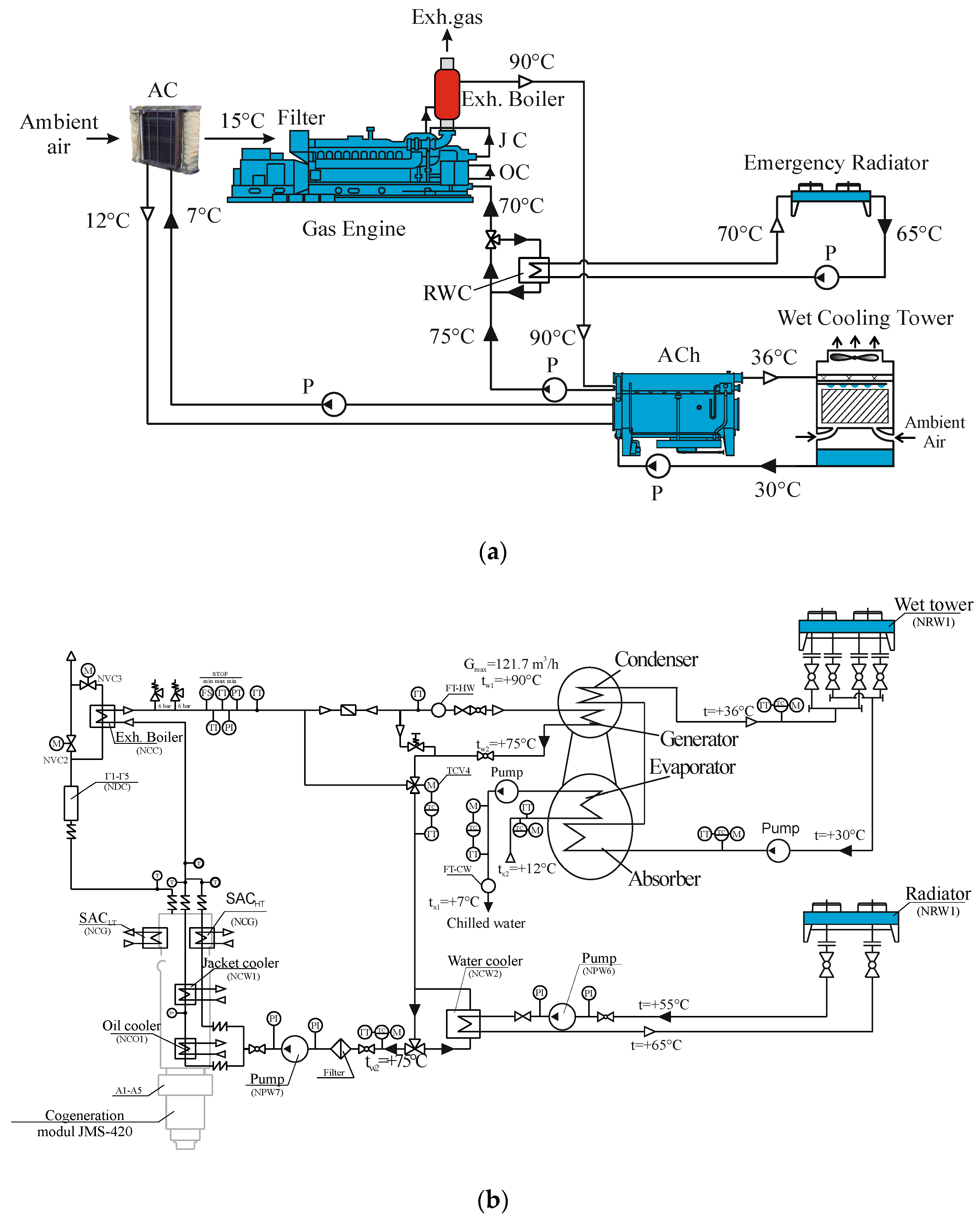
The efficiency of utilization of the heat released from gas engines for intake air cooling was investigated for the IES of the enterprise “Sandora”–“PepsiCo Ukraine” (Figure 1a). The monitoring data on the hot-water temperatures and flow rate were measured according to the heat utilization circuit (Figure 1b).
The return cooled hot water from the ACh is used as a coolant to extract heat from lubricating oil and the engine jacket. The IES includes two cogeneration modules based on Jenbacher gas engines JMS 420 GS-N.LC (INNIO Group, Tyrol, Austria; rated electric power PeISO = 1400 kW, heat power Qh = 1500 kW). The main rated characteristics of the Jenbacher gas engine JMS 420 GS-N.LC, applied as a driving one, at the ISO parameters (air temperature Tin.ISO = 298.15 K and relative humidity φISO = 30%) are the following: electrical power Pel.ISO = 1420 kW, heat power Qh = 1500 kW, specific gas fuel consumption be.ISO = 167.76 g/kWh [5].
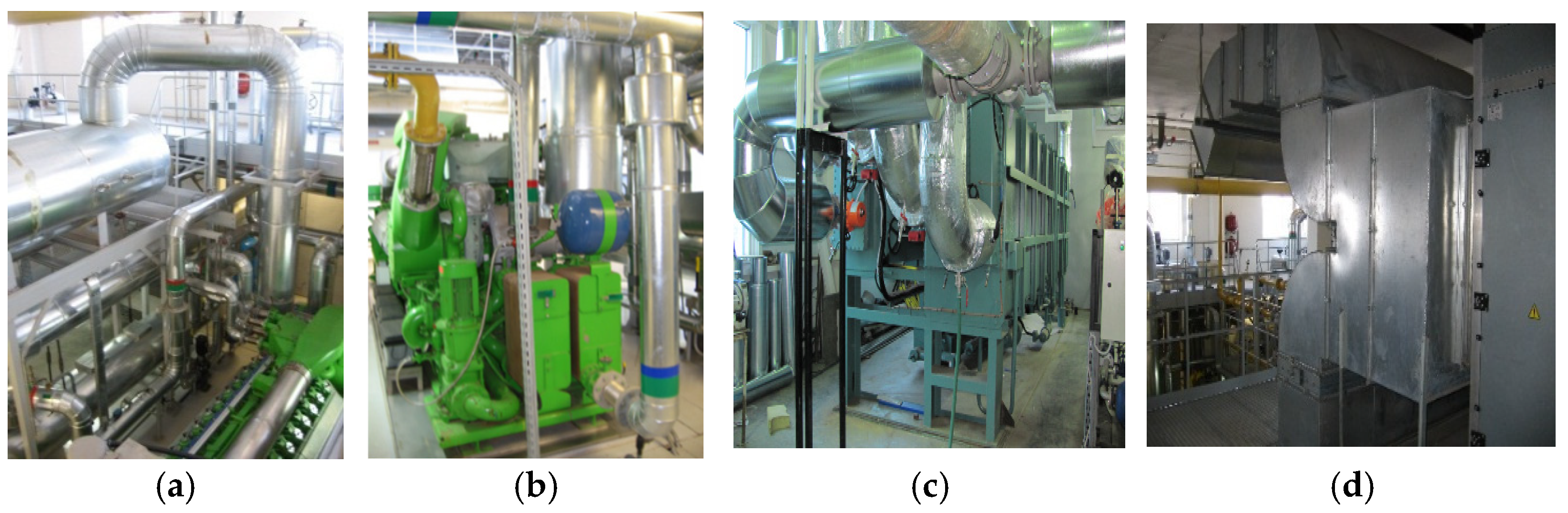
The heat rejected from lubricating oil, engine jacket cooling water, scavenge air–gas mixture and exhaust gas is converted in the AR-D500L2 Century (Century Corporation, Seoul, Republic of Korea) [94] absorption Li-Br chiller (cooling capacity 2000 kW) to produce refrigeration in the form of chilled water with a temperature of 7 °C. The refrigeration capacity is used to cover the technological cooling needs and to feed the central air conditioner intended for cooling the ambient air entering the machine room, from where the air is sucked by the engine turbocharger (Figure 2).
The central conditioner CIC Jan HREBEC 1LG4223-8AB60 has a cooling capacity of 350 kW and a volume air flow of 60,000 m3/h [97].
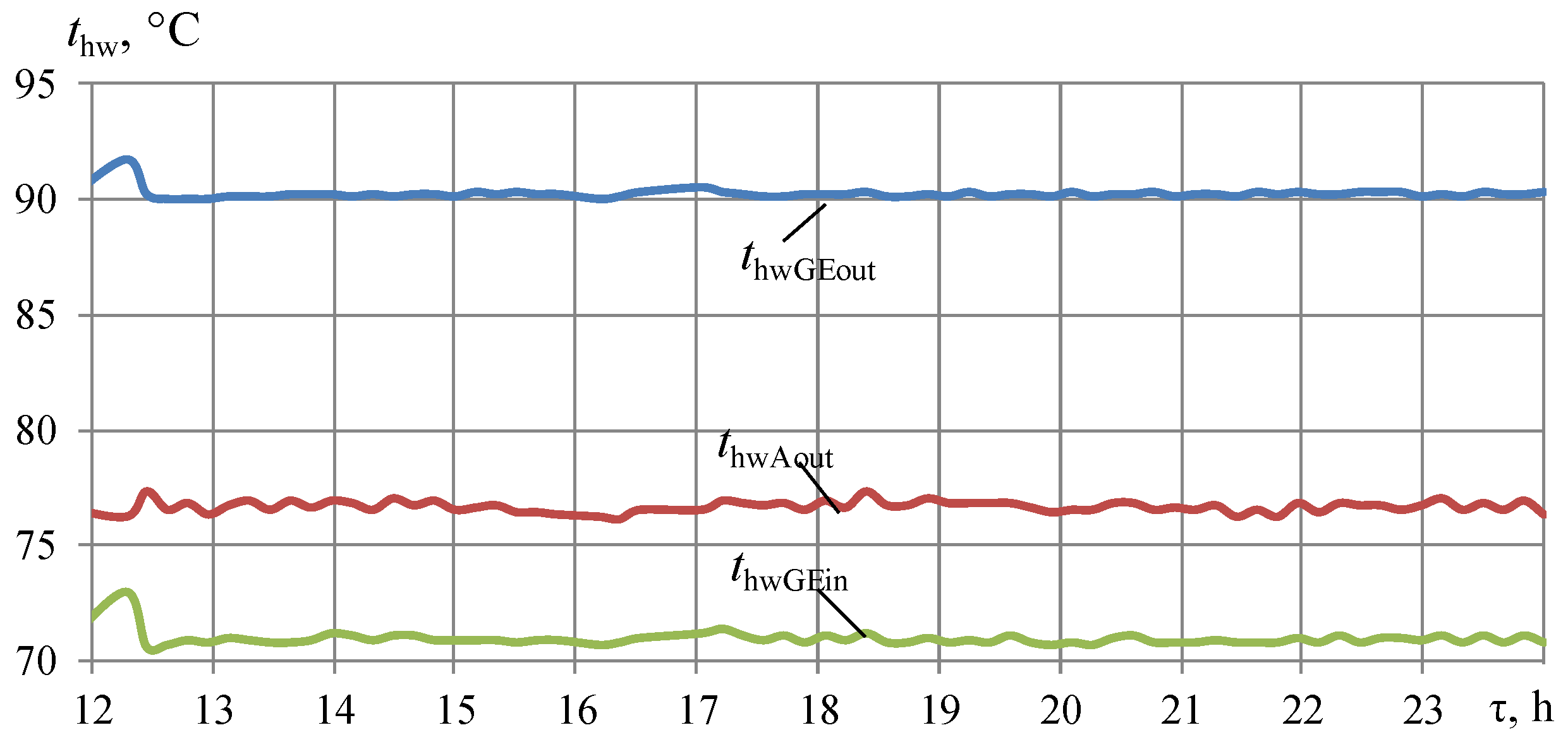
During monitoring, temperatures of hot water were measured at key points in the heat utilization system: at the outlet of the exhaust boiler (outlet of GE, inlet of ACh), thwGEout, at the outlet of ACh, thwAout, and return hot water, cooled in the emergency radiator, at the GE inlet thwGEin, chilled water from ACh tcwAout and return chilled water at the inlet of ACh tcwAin. Water temperatures were measured every 10 min throughout the day.
The volumetric flow rates of hot and chilled water were measured using Vzlet ERSV-410(510)L electromagnetic flowmeters installed in the corresponding water circuits, as shown in Figure 1. The hot-water flow rate is denoted as Ghw and the chilled water flow rate as Gcw. The maximum permissible relative error of the flow measurement was evaluated as δG = ±(0.9 + 0.15/v)%, where v is the water velocity in the measuring section, m/s. The relationship between water velocity, volumetric flow rate and nominal flowmeter diameter is provided in the note to Table 3.
The measurement ranges and metrological characteristics of all instruments are summarized in Table 3.
In Figure 1b, FT-HW—electromagnetic flowmeter for hot-water volumetric flow rate; FT-CW—electromagnetic flowmeter for chilled-water volumetric flow rate; TT—temperature sensor; PI—pressure gauge.
As an example, the relative errors in the heat flows calculated according to monitoring data on the heat of the hot water removed from the engine are indicated in Appendix A, Table A1, with the heat of the chilled water (coolant) generated in ACh (Table A2), the cooling capacity produced by ACh (Table A3).
The relative errors in the heat flows calculated according to monitoring data were determined by taking into consideration the error of measurement devices, methodological and systematic errors and were about 5–6%.
The monitoring data on daily changes of electrical power output Pel and volumetric gas fuel Bgas consumed by gas engine JMS 420 were measured using an ultrasonic gas meter KURS-01 G250 A1 and electricity meter SL 7000 Smart (SL761) accordingly (Table 3).
The volumetric gas fuel Bgas was used for the calculation of gas fuel heat Qgas and electrical efficiency ηel = Pel/Qgas.
The heat efficiency ηh = Qh/Qgas and total electrical and heat efficiency ηel+h = (Pel + Qh)/Qgas of IES were calculated by using the heat Qh released from GE according to the measured volume flow Ghw and temperatures of hot water at the outlet thwGEout and inlet thwGEin of GE.
The available cooling capacities Q0.ACh of ACh are limited by the heat of hot water Qh.ACh converted into refrigeration, which is limited by the hot-water temperature drop of about 15 °C optimal for ACh.
The monitoring data on the hot-water temperatures in the heat utilization system of conventional IES based on GE JMS 420 GS with ACh are shown in Figure 3 for the time interval τ = 12:00–24:00 (28 July 2017).
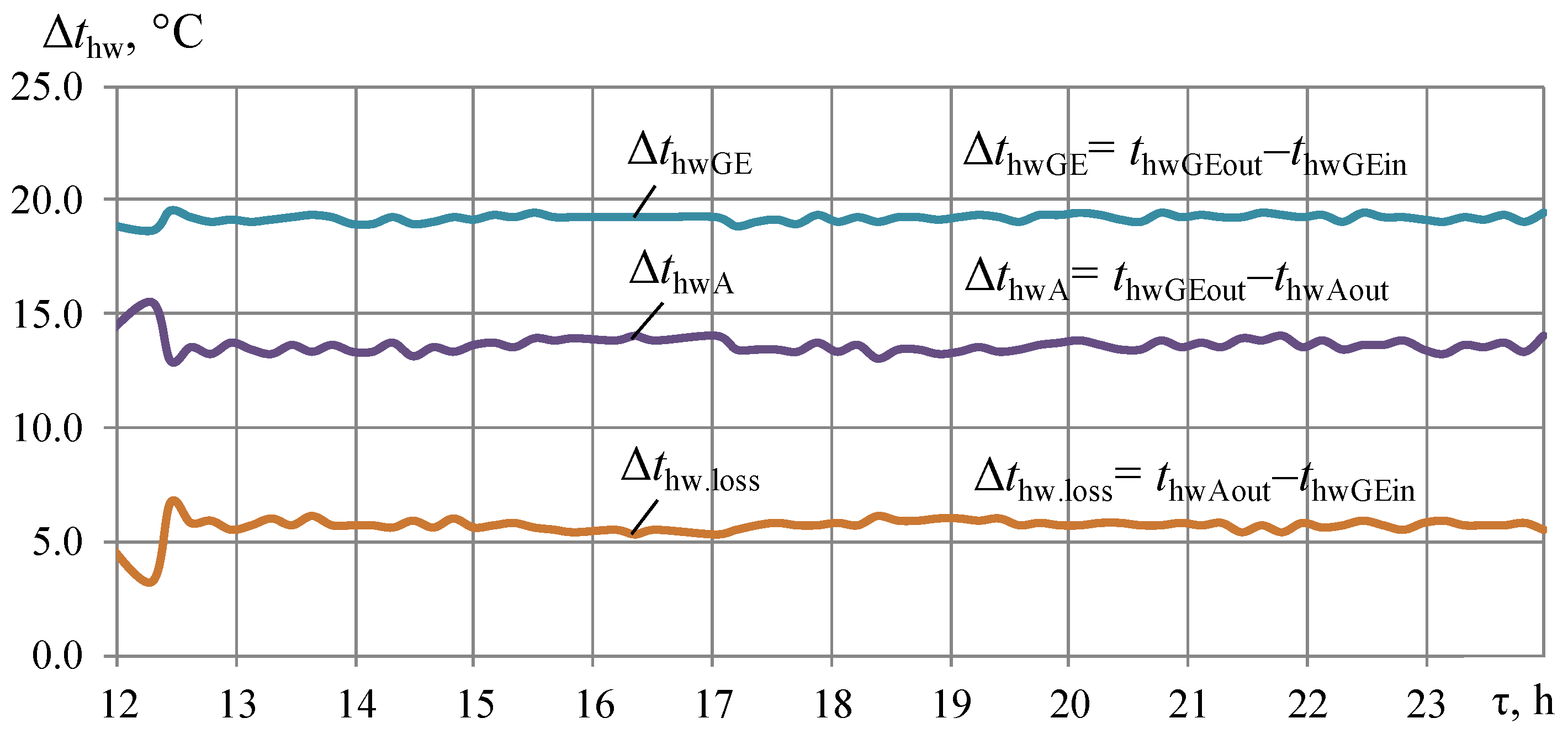
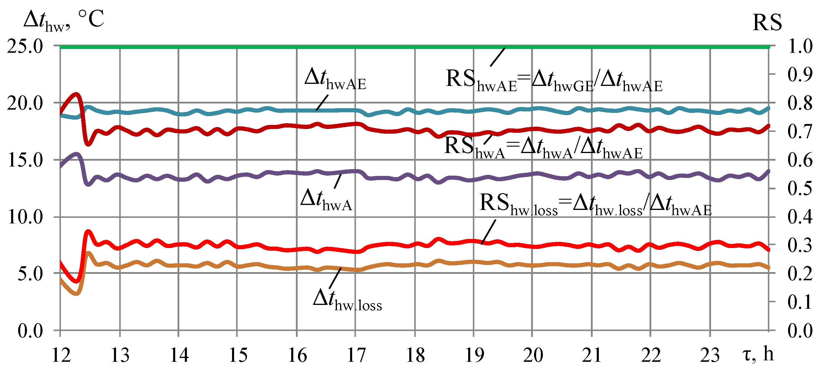
The current temperature drops of hot water due to recovery of its heat in ACh ΔthwA, caused by extracting heat into atmosphere in the emergency radiator Δthw.loss and overall temperature drops ΔthwGE in hot water from GE are presented in Figure 4.
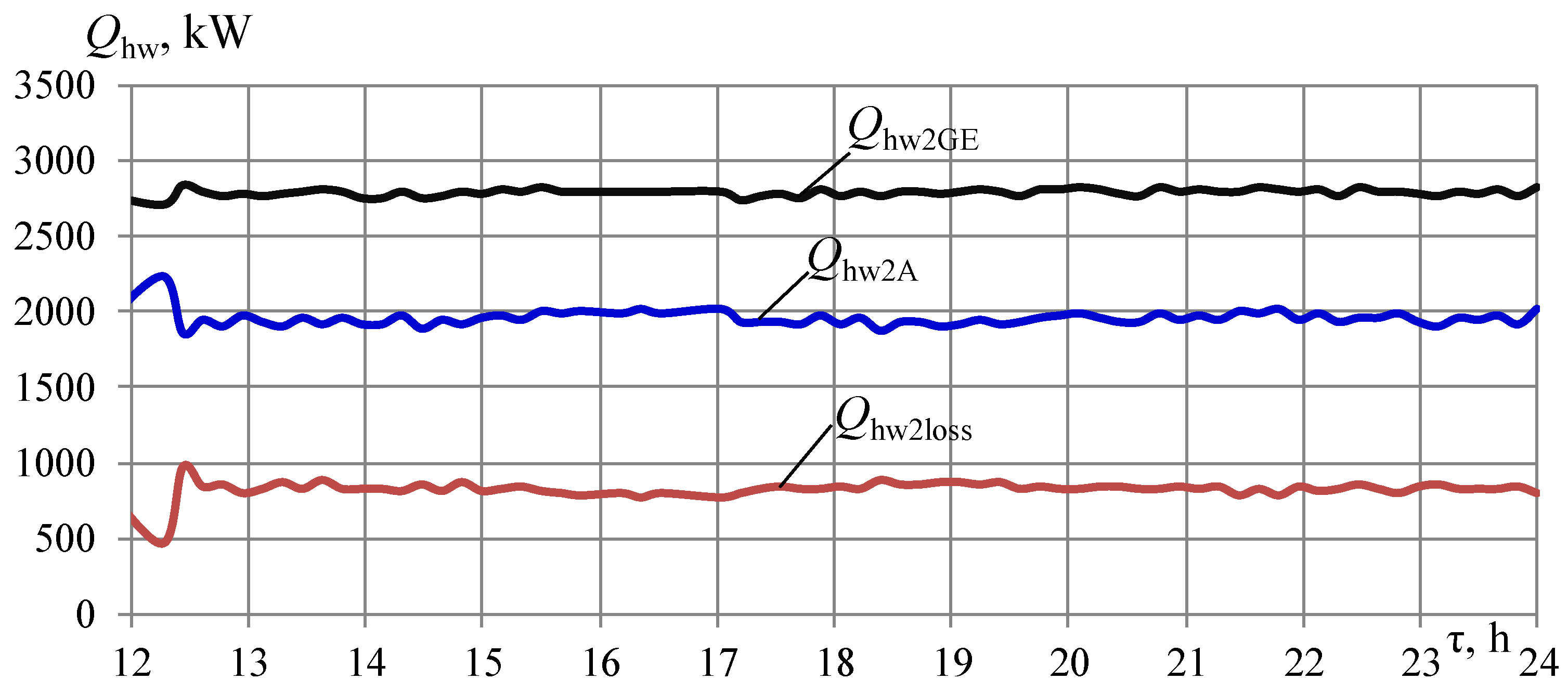
The overall heat Qhw2GE rejected from two GE, heat converted by ACh Qhw2A to refrigeration and the heat loss Qhw2loss left from ACh and extracted into the atmosphere by the radiator were calculated based on the monitoring data on water flow Gw and changes in temperature of water in the engine heat utilization circuit (Figure 3 and Figure 4).
Herewith, the following heat balances for two GE were conducted:
  • The overall heat released from two GE Qhw2GE = Gw cw (thwGEoutthwGEin);
  • Heat converted by ACh into cooling capacity Qhw2A = Gw cw (thwGEoutthwAout);
  • The heat loss Qhw2loss = Gw cw (thwAoutthwGEin).
The corresponding heat released from two GE Qhw2GE, converted by ACh into cooling capacity Qhw2A, and the remaining heat loss Qhw2loss removed by the radiator to the atmosphere, are depicted in Figure 5.
Herewith, the heat of hot water at 90 °C released from two GE Qhw2GE is about 2800 kW, i.e., one GE–QhwGE = 1400 kW, whereas heat converted by ACh to refrigeration for two GE Qhw2A is about 2000 kW, and for one GE–QhwA = 1000 kW; heat loss rejected into the atmosphere from two GE Qhw2loss is about 800 kW and from one GE–Qhw.loss = 400 kW, respectively.
Thus, the heat losses Qhw.loss in the heat-converting circuit of a typical IES are within 25 to 30% of the heat Qhw.GE produced by GE.
These heat losses Qhw.loss are caused by reducing the temperature of return cooled hot water at the GE inlet from about 75 °C to 70 °C, i.e., by a temperature difference Δthw.loss of about 5 °C as the issuing point for quantitative assessment of the deepness (level) of the released hot-water heat utilization by the rate of engine thermal stabilization (RS) and lifespan in the aspect of utilization (Figure 6).
The guidelines for Jenbacher engines provide detailed maintenance schedules and recommendations to mitigate the impacts of return cooled hot-water temperature at the GE inlet, exceeding the specified value of 70 °C on engine performance [5,28].
According to the guidelines for Jenbacher engines, for each 1 °C increase, the engine’s lifespan could decrease by about 2%, or for a 5 °C increase, by about 10%.
Considering engine intake air cooling and the deep utilization of released hot-water heat, required to provide thermally safe GE operation at the temperature of return cooled hot water as a coolant for engine jacket and lubricating oil at the inlet of engine not higher than 70 °C, as both aspects of engine sustainability due to thermal stabilization, the analogies in the criterion indicators for estimating the efficiency of solutions to the problem in both aspects can be drawn.
So far, with deeper cooling of intake air, estimated by its temperature drops Δtin, as well as deeper utilization of the heat released with hot water, evaluated by its temperature drops Δthw, the more thermally stabilized GE operation, the hot-water temperature drops Δthw are considered general factors affecting engine thermal stabilization and fuel-efficient operation. From the above, the corresponding cooling capacities Q0.in (first aspect) and heat Qhw converted to Q0 (second aspect), which are needed for sustainable operation and an adequate thermally stabilized level compared to the target magnitude assumed as a maximum of 100%, can be determined.
Thus, issuing from the generalized approach above, likewise, with the approach for estimating the RS due to intake air cooling in the first aspect [91], the RS of GE can be evaluated in the aspect of heat utilization by return cooled hot-water temperature deviation from the specified 70 °C (Figure 6).
Herein, the overall temperature drop of hot water, ΔthwGE = thwGEoutthwGEin, of about 20 °C, is equivalent to utilizing the overall heat released from GE involving both heat converted to refrigeration in ACh QhwGE = 1400 kW (with corresponding ΔthwA) and heat loss Qhw.loss = 400 kW extracted into the atmosphere in the emergency radiator (Δthw.loss). This temperature drop ΔthwGE is assumed to be the magnitude providing the maximum ratio RShwGE = 1.
Respectively, in the typical IES with ACh, the RShwA = ΔthwAthwGE ≈ 0.7…0.73. The additional increment as RShw.loss might be achieved due to utilization of the rest of the heat loss: RShw.loss = Δthw.lossthwGE ≈ 0.25…0.30. Herein, RShwA = ΔthwAthwGEQhwA/QhwGE and RShw.loss = Δthw.lossthwGEQhw.loss/QhwGE.
The calculation results on the engine stabilization rates RShw due to the utilization of the heat released from the GE are presented in Figure 6. Herewith, its full conversion provides a maximum magnitude of RShwGE of about 1.0 (100%).
As seen, in a typical IES with ACh the RShwA = ΔthwAthwGE ≈ 0.7…0.73, as well as the additional increment RShw.loss due to utilization of the rest heat loss RShw.loss = Δthw.lossthwGE ≈ 0.25…0.30 (Figure 6).
Here,
  • RShw.A—due to converting heat by ACh in a typical IES with ACh;
  • RShw.loss—additional increment due to utilization of the rest of the heat loss in the modified system.
According to the guidelines for Jenbacher engines, for each 1 °C increase in return cooled hot water at the GE inlet above the specified limit of 70 °C, the engine’s lifetime LT decreases by about 2%, or for a 5 °C increase, by about 10%.
For example, if the engine’s normal lifetime at 70 °C is 20,000 h (100%), operation at 71 °C could reduce this to around 19,600 h (2%); likewise, at 75 °C, it will be reduced to 18,079 h (90%), i.e., by about 10% (Table 2) [5,28].
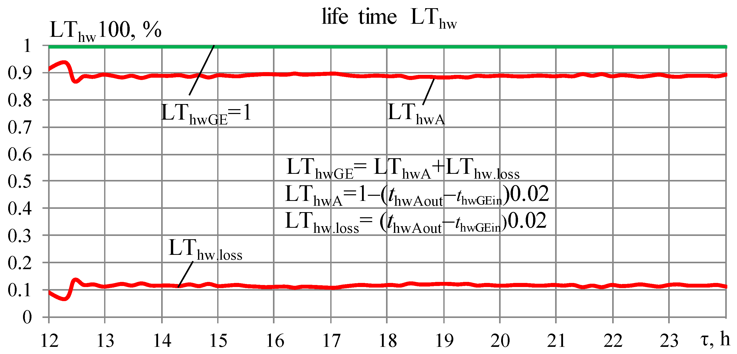
The calculation results on the level of engine long-term lifetime LThw due to utilization of the heat released from GE are presented in Figure 7.
As seen, full utilization of the released heat provides a maximum magnitude LThwGE of about 1 or 100% against LThwA of about 0.9 or 90% in typical IES. Herewith, the increment in LThwGE of 10% is gained due to the utilization of heat loss, converted by ECh into refrigeration for cooling the intake air.
The following correlations are applied.
There is a decrease in the level of engine lifetime ΔLThw.A caused by the increased temperature of hot water from ACh (before extraction of its heat by the emergency radiator into the atmosphere):
ΔLThw.A = (thwAoutthwGEin)0.02 = LThw.loss,
where 0.02 or 2% is a decrease in the engine lifetime for each 1 °C increase above the specified limit of 70 °C [5,28].
Corresponding reduced level of engine lifetime:
LThwGE = 1; LThwGE = LThwA + LThw.loss;
LThwA = LThwGE − (thwAoutthwGEin) 0.02; LThwA = LThwGE − LThw.loss;
LThw.loss = (thwAoutthwGEin) 0.02 = ΔLThw.A; LThw.loss = LThwGE − LThwA.
Furthermore, according to the guidelines and empirical data of Jenbacher gas engines, each 1 °C increase in return hot coolant at the inlet of GE above the specified 70 °C causes a reduction in total engine efficiency ηtot by 0.5% [5,28].
So, according to the guidelines for Jenbacher engines, there might be a reduction in overall engine efficiency by 0.5% for each 1 °C increase in return cooled hot water at the inlet of GE above the specified 70 °C [5,28]. Respectively, a decrease in the temperature of the return water from 75 °C after the ACh to 70 °C at the inlet of the GE, i.e., by 5 °C, leads to an increase in the engine’s total efficiency by 2.5%. This is caused by using the return water as a coolant for cooling the engine jacket and lubricating oil.
The effect of full utilization of the heat, released from GE, in the increase in total efficiency and heat efficiency of a modified IES compared to the typical version, is evident from the results in Figure 8 and Figure 9.
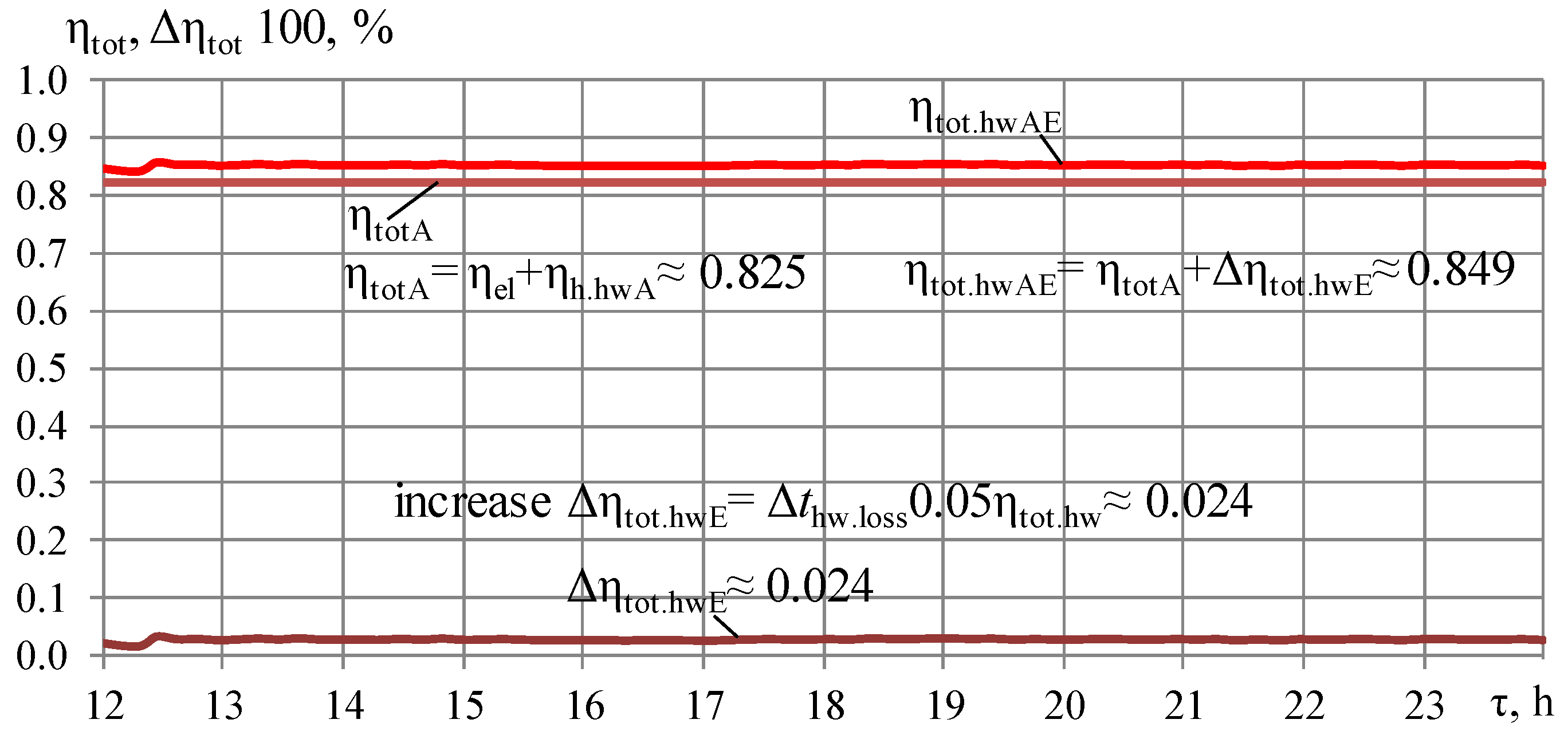
The daily variation in total electrical and heat efficiency ηtotA due to converting the heat of hot water by ACh in a typical IES with its temperature at the outlet of ACh of about 75 °C, its increment Δηtot.hwE due to utilization of the heat loss by ECh and their total efficiency ηtot.hwAE due to converting all the heat of hot water in ACh and ECh with temperature of hot water at the inlet of GE of about 70 °C are depicted in Figure 8.
As Figure 8 shows, full utilization of the heat released from GE, for instance, by ECh, provides lower temperatures of return cooled hot water as a coolant at the inlet of GE ≈70 °C compared to about 75 °C when there is incomplete utilization with heat losses extracted to the atmosphere in an emergency radiator, which enables avoiding overheating return water as a coolant by 5 °C.
The latter leads to an increase in GE total efficiency by about ΔηhwE.loss ≈ 2.4% according to a reduction in total efficiency by 0.5% for each 1 °C increase in return coolant temperature over 70 °C [5,28]. Herewith, the total efficiency ηtot.hwAE is increased to about 85% compared to the efficiency ηtotA ≈ 82.5% of basic typical IES with incomplete utilization of heat in ACh.
It should be noted that this effect is achieved solely through the full utilization of the heat released and assessed according to the guidelines for Jenbacher engines [5,28].
The following correlations are applied for calculation of the total efficiency of IES.
There is an increase in the total efficiency of GE due to reducing the temperatures of return cooled hot water as a coolant at the inlet of GE by Δthw.loss = 5 °C: from 75 °C, when incomplete utilization of the hot-water heat with heat losses, to 70 °C when converting the heat losses by ECh for cooling intake air: Δηtot.hw.loss = Δηtot.base Δthw.loss 0.005 = 0.024, or 2.4%, where 0.005 is the increase in GE total efficiency for each 1 °C drop in return hot coolant according to [5,28].
A typical IES with ACh without considering heat losses is as follows:
  • Electrical efficiency ηel = Pel/Qgas ≈ 0.45;
  • Heat efficiency ηh = Qh/Qgas ≈·0.5;
  • Total efficiency ηtot.base = ηel+h ≈ 0.95.
Typical IES with ACh with considering heat losses of about 75%:
  • Heat efficiency ηh.hwA = 0.75 ηh ≈·0.375;
  • Total efficiency ηel+h.hwA = ηel + ηh.hwA = 0.825.
Modified IES with ACh and ECh, converting heat losses for cooling intake air:
  • Increase in GE electrical efficiency by about Δηel.incr ≈ 2.0…2.5% due to cooling intake air in ECh by ΔtEin;
  • Increased total efficiency due to cooling intake air in ECh: ηel.incr+h.hwA = ηel.incr + ηh.hwA ≈ 0.82…0.84 (Figure 7);
  • Increase in GE total efficiency by about Δηtot.hw.loss ≈ 2.4% according to its increase by by 0.5% for each 1 °C drop in return hot coolant beyond 70 °C;
  • Increased total efficiency ηel+h.hwAE = ηel+h.hwA + Δηtot.hw.loss ≈ 0.849.
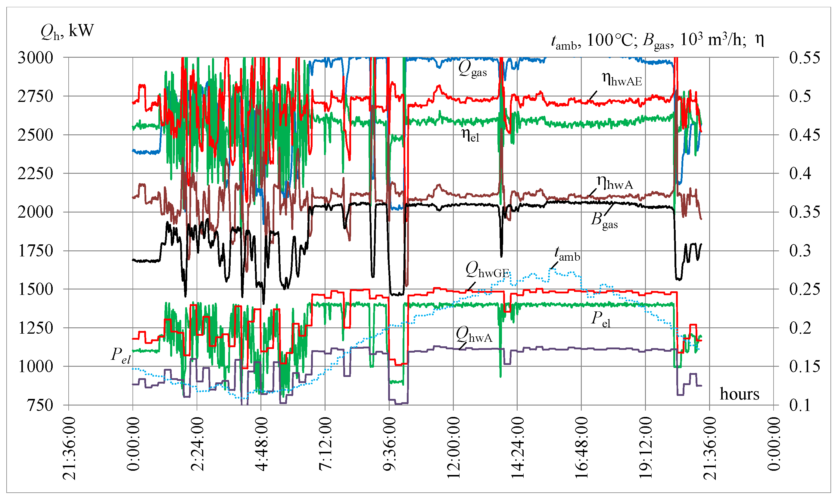
Herewith, the data on electrical power Pel and heat of gas fuel Qgas for the calculation of heat efficiency ηh = Qh/Qgas and electrical efficiency ηel = Pel/Qgas are taken from the monitoring results (Figure 9).
The results of monitoring data on daily changes in measured electrical power Pel, volumetric gas fuel Bgas consumed hourly by GE JMS 420, calculated heat of gas fuel Qgas, heat of hot water used by ACh QhwA and all the heat released from GE QhwGE, heat efficiency of typical IES with ACh ηhwA and modified IES with ACh and ECh using all the heat released ηhwAE (1 June 2019, Mykolayiv, southern Ukraine), are presented in Figure 9.
As seen, the electrical efficiency ηel of gas engine JMS 420 is about 0.47.
The real heat efficiency ηhwA of a typical IES with ACh is about 0.37, whereas the heat efficiency of a modified IES with ACh and ECh using all the heat released ηhwAE is about 0.5.
Herewith, the monitoring data on daily changes in electrical power output Pel, kW, and volumetric gas fuel Bgas, m3/h, consumed by gas engine JMS 420, were measured using an electricity meter SL 7000 Smart (SL761) and ultrasonic gas meter KURS-01 G250 A1 accordingly (Table 3).
The volumetric gas fuel Bgas, m3/h, was used for the calculation of gas fuel heat Qgas, heat efficiency ηh = Qh/Qgas and electrical efficiency ηel = Pel/Qgas.
Gas fuel heat Qgas is calculated according to the measured volumetric gas fuel Bgas: Qgas = Bgas LHV, where LHV = 9500 kWh/Nm3.
Respectively, the heat efficiency of the modified system is calculated as ηhwAE = Qh/Qgas, where Qh = QhwGE—heat of utilized hot water in the modified system; the heat efficiency of the typical system ηhwA = QhwA/Qgas, with QhwA—heat of hot water utilized by ACh in the typical system.
The overall heat QhwGE rejected from GE, the heat converted by ACh QhwA to refrigeration and the heat loss Qhwloss left from ACh and extracted into the atmosphere by the radiator were calculated based on the monitoring data on water flow Gw and changes in temperature of hot water in the engine heat utilization circuit (Figure 3 and Figure 4).
Herein, the following heat balances for GE were conducted based on 0.5Gw (Gw is the hot-water flow for two GE):
  • The overall heat released from GE QhwGE = 0.5Gw cw (thwGEoutthwGEin);
  • Heat converted by ACh into cooling capacity QhwA = Gw cw (thwGEoutthwAout).
The total efficiency of IES was calculated by using electrical power output Pel and the heat Qh utilized: ηel+hwAE = (Pel + QhwAE)/Qgas for modified system and ηel+hwA = (Pel + QhwA)/Qgas for a typical system.
These findings substantiated the importance of maintaining the specified return cooling water temperature of 70 °C to ensure the efficiency and longevity of Jenbacher gas engines.
Therefore, the rational design of a heat recovery system providing conversion of all the heat released from GE is crucial to prevent deviations from 70 °C, which can lead to significant performance losses and reduced engine lifetime.
So, the next step in the analysis is aimed at assessing the efficiency of converting the heat losses, inherent in typical IES with ACh, into refrigeration for cooling engine intake air by combining ACh and ECh as an example of the simplest chiller in terms of design and ease of implementation into a typical heat recovery system.

3.2. A New Approach to Engine Thermal Stabilization in Both Aspects: Cooling Inlet Air and Full Utilization of the Heat Released

Regarding deeper cooling intake air, meaning more thermally stabilized and fuel-efficient GE operation, a further step in the investigation is focused on assessing the influence of cooling inlet air by ECh, converting the heat loss, on the engine stabilization rate RSin as a general factor, affecting engine thermal and fuel stabilization [91].
As a thermally stabilized and fuel-efficient operation of GE takes place at reduced temperatures due to cooling intake air, the RSin is determined as a drop in actual cooled air temperature related to its target magnitude, providing maximum allowable depth of air cooling and the RSin accordingly.
Taking into account the temperature increase Δtincr = 5 °C, caused by heat influx from MR through the wall of the air duct to cooled air of mass flow 2G (4 kg/s) in modified IES, the needed cooling capacities Q0.15G2 provide 15 °C with Δt15 at the central AC outlet and tin = 20 °C with Δtin20 at GE inlet accordingly.
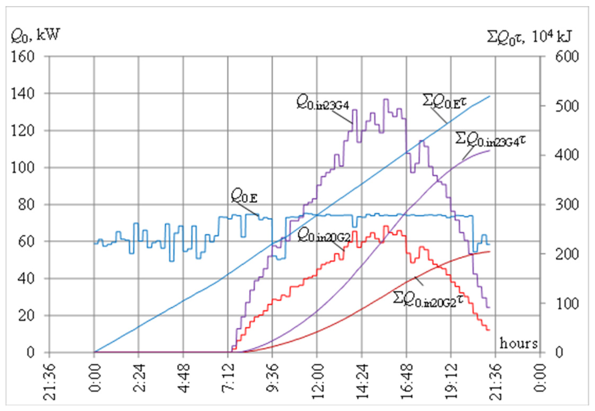
The values of cooling capacities Q0.in23G4 required in a typical system for cooling ambient air with 4G by ACh to 15 °C at the outlet of AC with ACh and to 23 °C at the GE inlet accordingly (increased by 8 °C) and Q0.15G2 in the modified system when air temperature at the ACh outlet is 15 °C and at the GE inlet 20 °C (increased by 5 °C), available cooling capacities Q0.E due to converting the heat loss by ECh and their summarized values ΣQ0.in23G4 τ, ΣQ0.15G2 τ and ΣQ0.E τ are depicted in Figure 10.
As shown, the available cooling capacities of ECh Q0.E are enough to cover the needs Q0.20G2 and ΣQ0.20G2 τ for cooling air of twice flow 2G to 20 °C at the GE inlet, which is increased by 5 °C due to heat influx to cooled air in the air duct, compared to its temperature of 15 °C at the AC outlet in the modified cooling system.
In turn, in a typical IES, when ambient air of 4G flow is cooled by ACh and mixed with the air in the machine room before being sucked by GE, the temperature of the mixed air is increased by 8 °C according to monitoring data [31]. This leads to considerably enlarged cooling capacities Q0.in23G4 spent in the typical system for cooling air of flow 4G to temperatures of about 23 °C at the GE inlet (15 °C at the ACh outlet), which are even higher than tin = 20 °C at the GE inlet with less cooling needs Q0.20G2 and ΣQ0.20G2 τ in the modified cooling system.
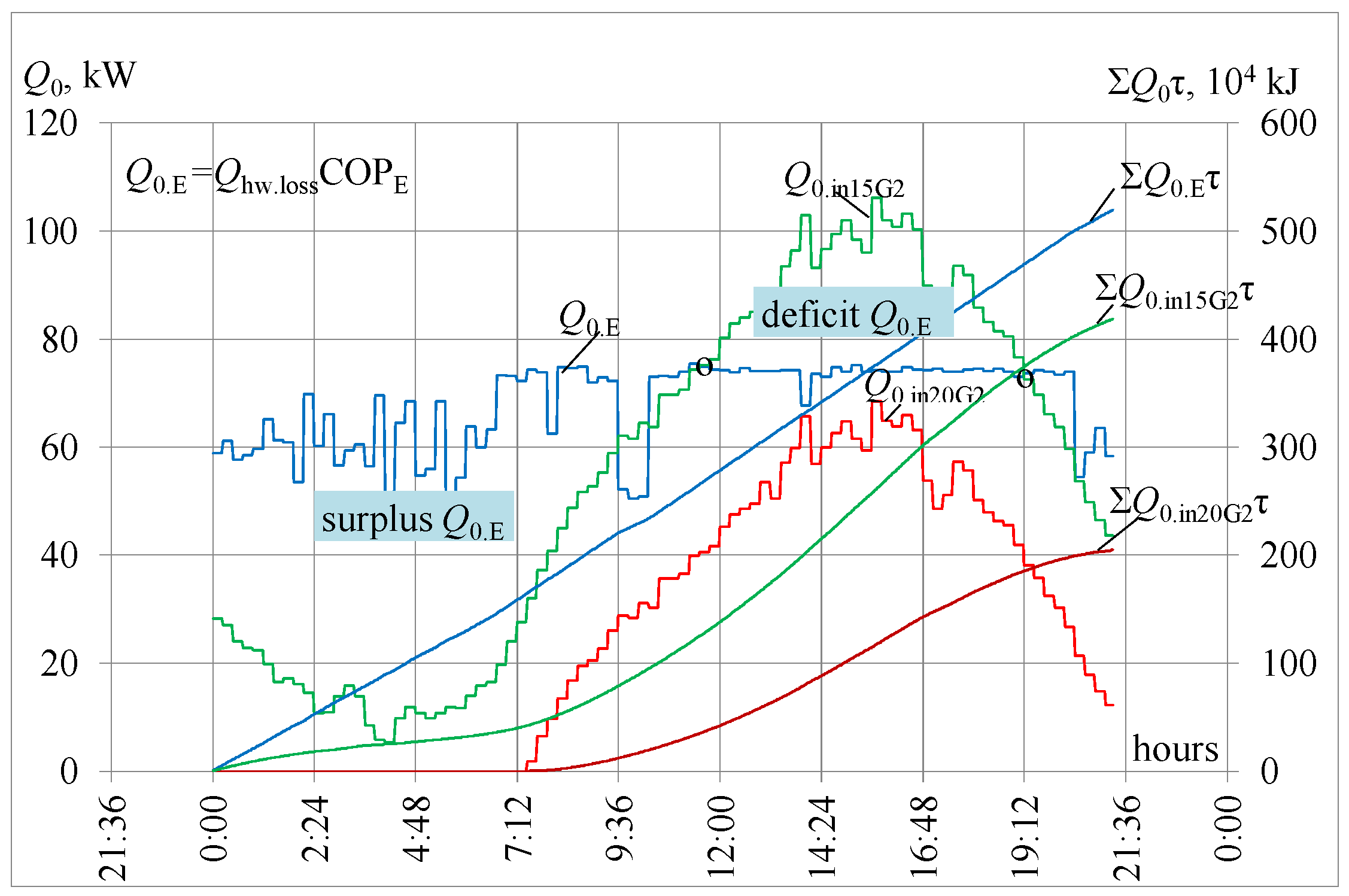
Regarding deeper cooling inlet air, the more thermally stabilized GE operation, the cooling capacities Q0.in15G2 needed for cooling ambient air of twice flow 2G to 15 °C at the GE inlet (10 °C at the AC outlet) in the modified system are assessed (Figure 11).
Daily changes in available cooling capacities Q0.ECh of ECh converting heat loss and cooling capacities Q0.in20G2 and Q0.in15G2 needed for cooling ambient air of twice flow 2G to 20 °C at the inlet of GE (15 °C at the outlet of AC with ACh) and to 15 °C at the inlet of GE (10 °C at the outlet of AC with AECh) in the modified system, and the corresponding sum of refrigeration energy ΣQ0.in20G2 τ, ΣQ0.in15G2 τ and ΣQ0.E τ, are depicted in Figure 11.
As can be seen, the sum of available ECh cooling energy ΣQ0.E τ is enough to cover the needs ΣQ0.20G2 τ and ΣQ0.15G2 τ for cooling air to 20 °C and 15 °C at the GE inlet (15 °C and 10 °C at AC outlet) in the modified cooling system, whereas, to cover the current cooling needs Q0.15G2 by ECh cooling capacities Q0.E, it is necessary to recoup the current excesses of Q0.E at lower ambient air temperatures to compensate for the lack of Q0.E at increased ambient air temperatures within an interval from 12 to 19 h when Q0.E is less than Q0.in15G2. This might be conducted by applying thermal energy storage (TES) technology or by involving the cooling capacity of ACh.
Based on the above, the temperature of 15°C for air at the GE inlet (10 °C at the AC outlet) might be assumed as a target magnitude ensuring the sustainable operation of the GE with thermal stabilization rate RSin15 = 1. Such an assumption enables assessment of the thermal stabilization rate RSE provided by ECh, converting the heat loss for cooling ambient air at the GE inlet by the available temperature drops ΔtEin related to cooling inlet air by Δtin15 to 15°C at the GE inlet (by Δtin10 to 10 °C at AC outlet with AECh) as the target maximum value.
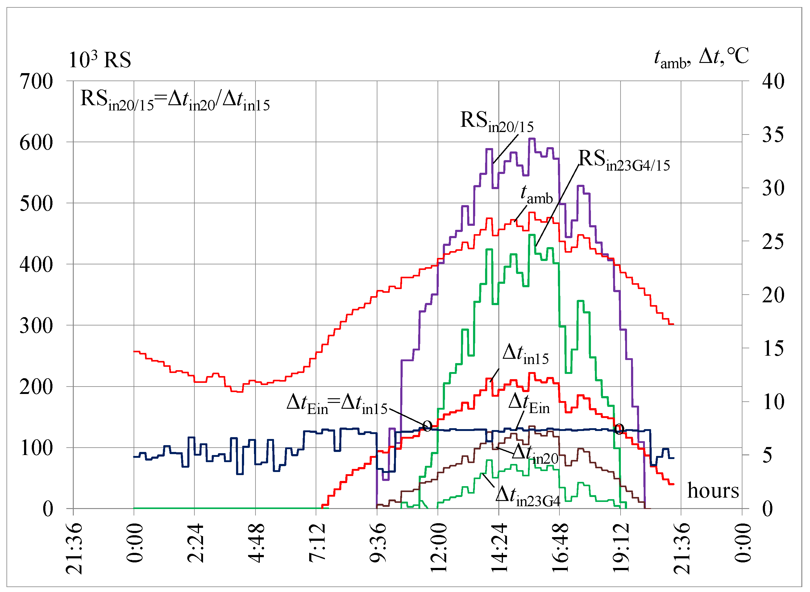
The calculation results of engine stabilization rates RSin23G4/15G2 when cooling sucked air to 23 °C at the GE inlet in a typical system, as well as RSin20/15G2 in the developed system with an air duct when cooling sucked air by Δtin20 to 20 °C at GE inlet, in both cases related to RSin15 when cooling inlet air by Δtin15 to 15 °C at GE inlet as the target maximum magnitude, are presented in Figure 12.
As can be seen, the maximum daily rate of stabilization RS20/15G2 is about 0.6 when the intake air of 2G cooling by Δtin20 to 20 °C at GE inlet (by Δt15 to 15 °C in AC with ACh) in the modified system against RSin23G4/15G2 of about 0.4 when intake air of 4G cooling by Δtin23G4 to tin of about 23 °C in the typical variant (Figure 6).
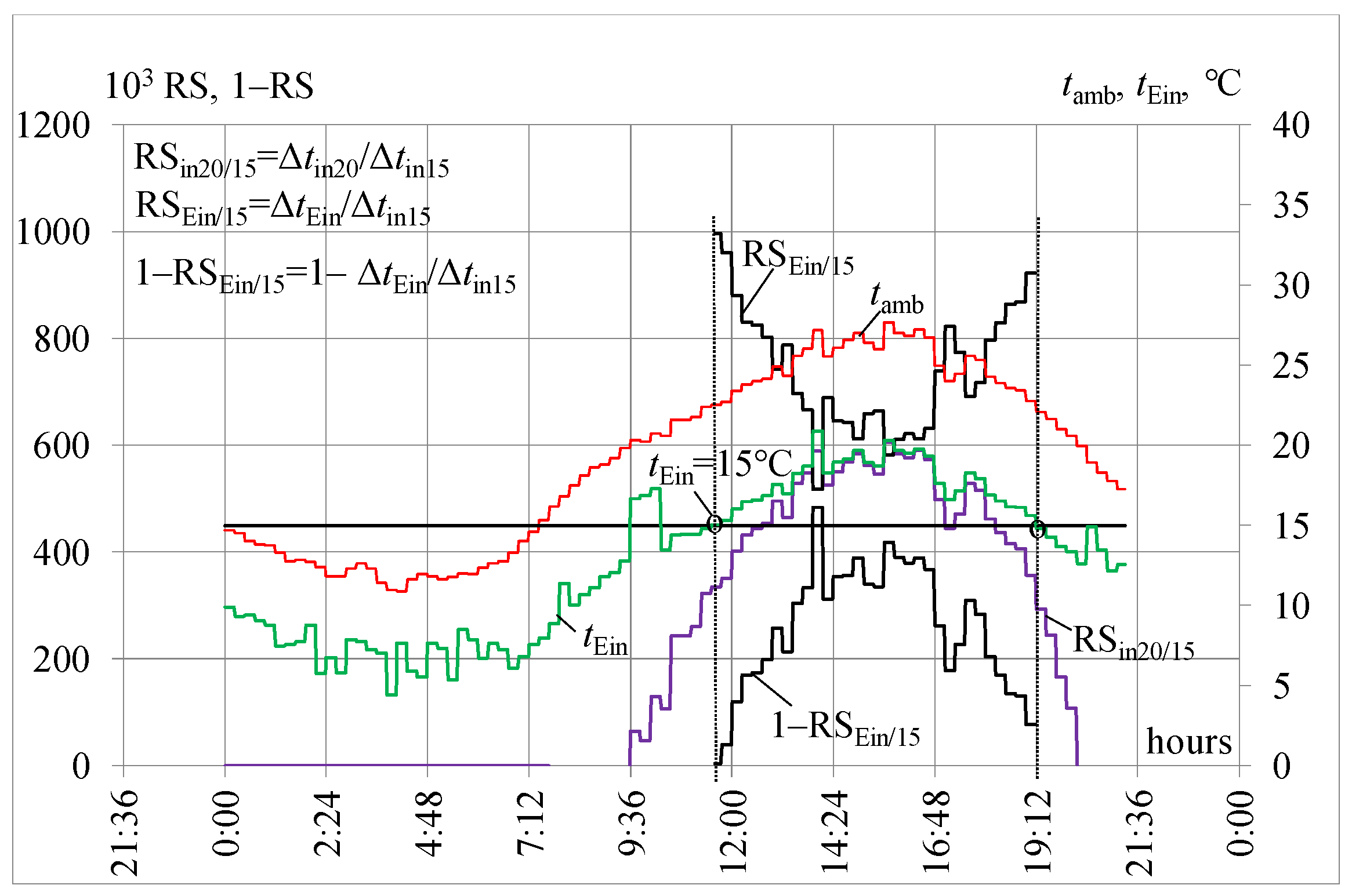
The range of the lack of ECh cooling capacity, exposed by exceeding the available temperature drop ΔtEin by the needed values Δtin15 for cooling air to 15 °C at the GE inlet, is limited by the points of coincidence ΔtEin = Δtin15 (Figure 12) or tEin = 15 °C (Figure 13). Herein, the conditional lack (deficit) in the rate of thermal stabilization as 1 − RSEin/15 varies from 0 to 0.4 accordingly (Figure 13).
The findings on the rate of engine thermal stabilization RS analysis, based on daily monitoring data on intake air cooling processes, are further extended over the yearly operation taking into account the actual varying climatic parameters to calculate the current and annual average weighted RS of GE with different cooling systems.
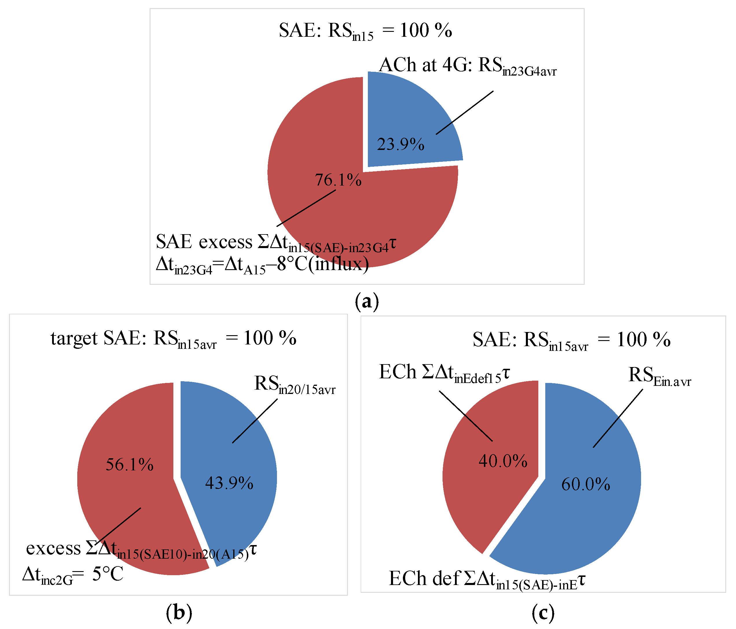
The average weighted rate RS20/15avr = ΣΔtin20 τ20/ΣΔtin15 τ15 of the modified system with ACh and cooled air sucked through a duct is calculated for actual temperature drops Δtin20 due to cooling air at the inlet of the engine to 20 °C (15 °C in AC with ACh) related to Δtin15 for 15 °C at the GE inlet (10 °C in AC with stage SAECh) accepted as a target minimum temperature (Figure 14b).
Similarly, the annual average weighted rate RSEin.avr = ΣΔtEin τEin/ΣΔtin15 τ15 of the modified system with ECh using heat loss is calculated (Figure 14c) for the available temperature drop ΔtEin (Figure 12).
The annual average weighted rate RSin23G4avr for a typical case with ACh and cooled air sucked from machine room RSEin.avr is depicted in Figure 14a.
As can be seen, the annual average weighted rate RS20/15avr of GE when cooling ambient air in ACh to 15 °C at AC outlet and further preheating cooled air in a duct to 20 °C at the GE inlet in the modified system (Figure 14b) is nearly double the annual rate RSin23G4avr of the GE with a typical cooling system (Figure 14a): 44% against 24%. In the typical system, ambient air of 4G flow is cooled in ACh to 15 °C and injected into the machine room, from which the mixed air is sucked by the engine turbocharger at 23 °C. In turn, ECh converting heat loss enables RSEin.avr of 60%.
  • RS20/15G2—cooling inlet air of 2G by Δtin20 to tin = 20 °C at GE inlet (15 °C at AC outlet with ACh) related to cooling inlet air by Δtin15 to tin = 15 °C at GE inlet (10 °C at AC outlet with SAECh) as a target rated value for the modified system;
  • RSEin/15—cooling inlet air of 2G by ΔtEin reduced by 5 °C compared to ΔtE calculated according to heat balance (Equation (7)) to consider heat influx;
  • RSin23G4/15G2—cooling inlet air of 4G by Δtin23 to tin = 23 °C at GE inlet (15 °C at AC outlet with ACh) in a typical system related to cooling inlet air by Δtin15 to tin = 15 °C at GE inlet (10 °C at AC outlet with SAECh) as a target rated value in the modified system.
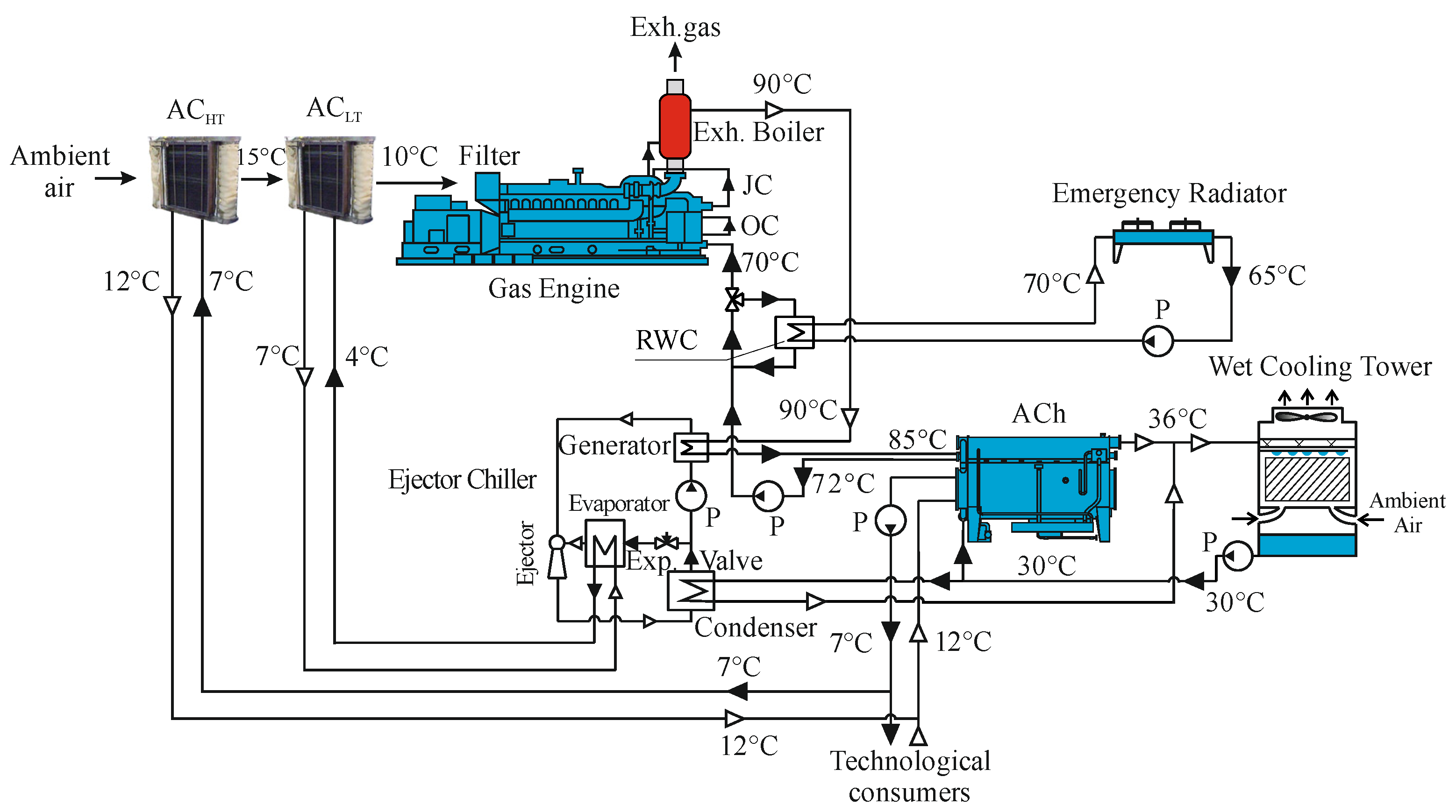
The developed modified IES, synthesized from the result of analysis, is depicted in Figure 15.
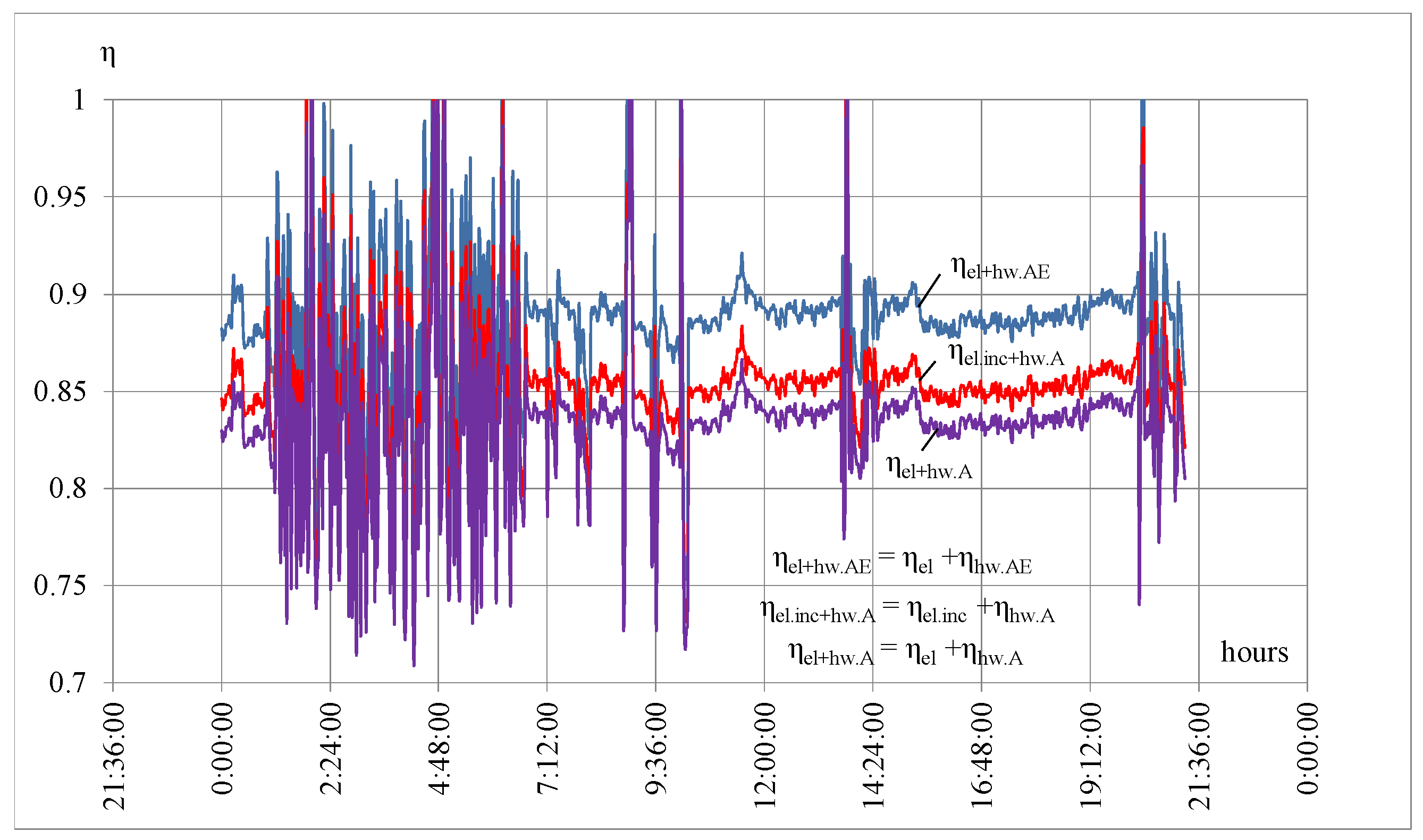
Daily changes in the overall electrical and heat efficiency due to heat transformed by ACh to refrigeration for the outer needs without intake air cooling ηel+hw.A and with engine intake air cooling by ECh ηel.inc+hw.A using heat loss, the overall efficiency due to converting heat to refrigeration for outer needs by both ACh and ECh without intake air cooling ηel+hw.AE, are presented in Figure 16 [31].
When the excess heat (heat loss) is transformed by ECh to refrigeration, used for lowering the GE-sucked air temperature to generate additional electricity and boost electrical ηel.inc and the overall efficiency ηel.inc+hw.A, the heat efficiency ηhw.A remains the same (Figure 16).
As Figure 16 shows, the increment ηtot.Eloss = ηel.inc+hw.A − ηel+hw.A ≈ 0.022, or 2.2%, due to cooling engine inlet air by ECh converting the heat loss, extracted into the atmosphere in a typical case, is quite close to its value Δηhw.loss = 0.024, or 2.4%, (Figure 8) gained due to reducing the return hot-water temperature by 5 °C, issuing from the reduction in the overall engine efficiency by 0.5% for each 1 °C above 70 °C [5,28].
Thus, the hypothesis of converting the heat loss, usually extracted into the atmosphere, by ECh boosting the ACh to ensure the return hot water at specified 70 °C and to cool the GE inlet air has been satisfied quantitatively from both aspects of engine thermal stabilization: through full utilization of the heat released from GE, on the one hand, and by cooling engine inlet air, on the other hand. In both cases, the engine stabilization rates RShw (Figure 6) due to converting the hot-water heat and RSin (Figure 12) due to cooling engine inlet air have been applied as indicators.
Moreover, in the case of utilizing the heat, the engine stabilization rates RShw are associated with the level of engine lifetime LThw as an additional indicator according to [5,28], which quantitatively estimates the reinforced impact of the released heat utilization on the engine’s sustainable operation.
Thus, the full utilization of the return hot-water heat ensures its temperature at the GE inlet of 70 °C and increases the engine stabilization rate from basic RShw.A = 0.7, or 70%, to RShwGE = 1.0, or 100, which leads to an increased level of engine lifetime from LThwA = 0.9, or 90%, at 75 °C for typical case to LThwGE = 1, or 100%, at 70 °C for modified IES.
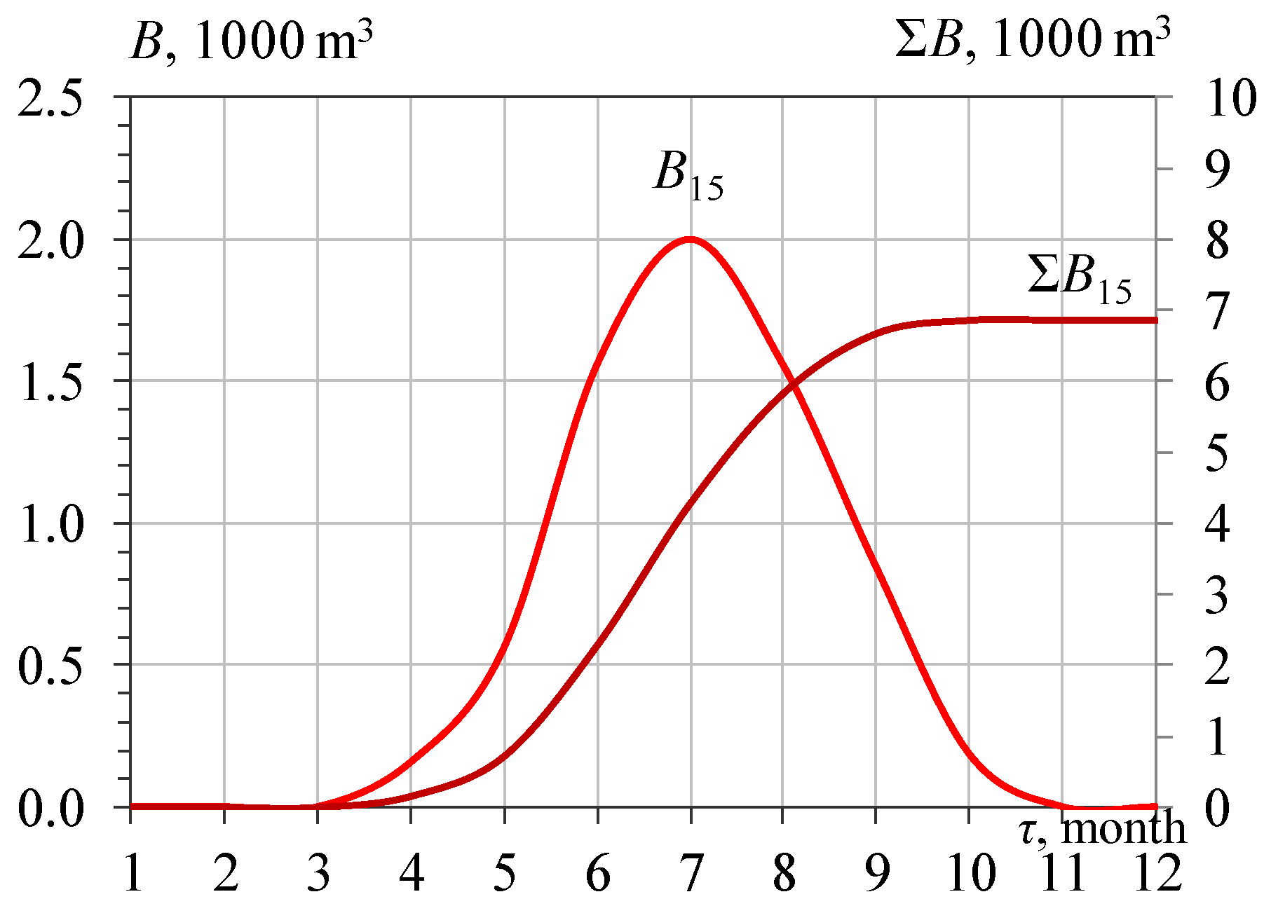
The application of the developed combined two-stage engine inlet air cooling system with AECh enables the engine operation at a practically stabilized low sucked air temperature at varying climatic conditions, which results in monthly B and annual ΣB (Equation (2)) reductions in fuel consumption (Figure 17).
Thus, by minimizing the heat influx to cooled sucked air from the machine room environments, the two-stage air cooling system enables engine performance at stabilized low intake air temperatures under varying climatic conditions.
The considered method of design focuses on providing just the initial basic data as rational technical characteristics for further complicated, detailed economic analysis.

4. Conclusions

4.1. Challenges

Sustainable performance of combustion engines and IES as a whole at a safe thermal level with high fuel effectiveness is possible due to cooling intake air and full utilization of the heat released with hot water and converted into refrigeration, typically by the absorption of a lithium-bromide chiller (LBCh) as the most efficient and widespread. Herewith, the return cooled hot water from the LBCh is used as a coolant for removing the heat from the engine jacket and lubricating oil, for which the temperature at the engine inlet is not to be higher than 70 °C to ensure a safe thermally stabilized performance of the engine.
Incomplete utilization of the heat, caused by a hot-water temperature drop in LBCh of about 15 °C against the available 20 °C, leads to exceeding this value and shortening the engine lifetime by 10% at 75 °C.
To ensure thermally stable performance of the engine in a conventional IES, the residual heat left from LBCh is rejected into the atmosphere by the emergency radiator with inevitable heat losses of about 25% as the “cost” for safe engine performance.

4.2. Solutions

The aspect of enhancing the sustainable performance of an IES due to ensuring the long-term lifetime of operation through full recovery of the heat released from the GE to provide a temperature of return cooled hot water at the entrance of the GE no higher than 70 °C was investigated. Such a constraint is rigorous because the return cooled hot water is used as a coolant for the engine jacket and lubricating oil.
The universal methodological basis to satisfy the challenges from the aspects of cooling inlet air and full utilization of the heat from the GE was developed based on the rate of thermal stabilization (RS), calculated as a ratio of the actual temperature drop of air Δtin (hot water Δthw) to its design value.
Herewith, the RS is considered the unified criterion to combine both aspects in a joint chain through the utilization of the heat loss of about 25%, inherent in a conventional IES, for cooling the engine intake air and thereby enhancing engine efficiency.
It is proven that the available ECh cooling capacities Q0.E, gained due to the utilization of the heat loss, are enough to cover the current Q0.in20G2 and sum needs ΣQ0.in20G2τ for cooling air to 20 °C at the GE inlet.
This provides an enhancement in the annual average weighted rate RSavr due to cooling intake air by converting heat loss in ECh to about 60% in a modified cooling system with cooled air transported by a special duct, against 24% for the typical case with LBCh and cooled air sucked from the machine room.
Moreover, cooling the intake air by converting the heat loss enables an absolute increase in the GE’s total efficiency by 2.0…2.5%.
The hypothesis of estimating the efficiency of the exhaust heat utilization by the rate of thermal stabilization RS has been further extended through its application for evaluating the level of engine lifetime LT from basic LThwA = 90% for a typical system with incomplete utilization of the heat in LBCh to LThwGE = 100% for a modified system with full utilization of the heat, including heat loss converted in boost ECh.
Thus, the bridge between the full utilization of the heat released and cooling intake air was built based on the unified criteria adapted to provide a sustainable long-term lifetime and fuel-efficient operation of GE as a prosperous trend in IES and energetics as a whole.
The further investigation aims to evaluate the input of intake and charge air cooling separately upon the GE thermal stabilization to develop a universal cooling system to cover actual cooling needs by redistributing available capacity between both objects of cooling.

Author Contributions

Conceptualization, A.R., M.R. and S.F.; methodology, A.R., R.R., S.F. and A.Z.; software, A.R., R.R., S.F. and A.Z.; validation, A.R., R.R., S.F. and A.Z.; formal analysis, Y.L., A.R., F.Z. and S.F.; investigation, Y.L., A.R., R.R., S.F. and A.Z.; resources, Y.L., A.R., F.Z., S.F. and A.Z.; data curation, Y.L., A.R., F.Z., S.F. and A.Z.; writing—original draft preparation, AR., S.F. and A.Z.; writing—review and editing, A.R., M.R. and S.F.; visualization, A.R., S.F. and A.Z.; supervision, A.R. and S.F.; project administration, A.R., F.Z. and M.R.; funding acquisition, Y.L. All authors have read and agreed to the published version of the manuscript.

Funding

This research received no external funding.

Data Availability Statement

The original contributions presented in this study are included in the article. Further inquiries can be directed to the corresponding author.

Conflicts of Interest

Author Feng Zheng was employed by the company Yangzhou COSCO Shipping Heavy Industry Co., Ltd. The remaining authors declare that the research was conducted in the absence of any commercial or financial relationships that could be construed as a potential conflict of interest.

Nomenclature

ACair cooler
ACh, LBChabsorption lithium-bromide chiller
AEChabsorption-ejector chiller
CDHcooling degree hour: CDH = Δta τ°C·h
COPcoefficient of performance
EChejector chiller
Gair mass flow rate, G = 2 kg/s; 2G = 4 kg/s; 4G = 8 kg/skg/s
GEgas engine
SAEChstage absorption ejector chiller
RSrate of thermal stabilization
Symbols and units
Bfuel reduction per hour due to air coolingkg/h
ΣBannual fuel reductiont
bespecific fuel consumption (SFC) g/kWh
Δbe specific fuel consumption reductiong/kWh
dambambient air absolute humidityg/kg
Gaair mass flow ratekg/s
Pepower output kW
Q0overall cooling capacitykW
q0specific cooling capacity—per unit air mass flow ratekW/(kg/s) or kJ/kg
tTemperature°C
tambambient air temperature°C
ta2outlet air temperature °C
t0refrigerant boiling temperature°C
ξspecific heat ratio of the overall heat (latent and sensible) related to sensible heat
τtime intervalh
φamb ambient air relative humidity %
Δtair temperature decrease K, °C
Subscripts
15…25for temperatures 15 °C…25 °C
aAir
ambambient air
avraverage weighted magnitude
G2,G4for 2G = 4 kg/s; 4G = 8 kg/s
hwhot water
inInlet
incIncrease
maxMaximum
optOptimal
ratRational
wWater

Appendix A

Table A1. The relative errors in determining the heat of hot water released from GE.
Heat Released from GERelative Errors
Systematic ErrorsConfidence Probability
p = 0.9p = 0.68
QhwGE Δ Q hwGE Q hwGE Δ Q hwGE Q hwGE Δ Q hwGE Q hwGE
128060.0042890.005110.002311
228260.0042870.0051080.00231
327850.0042880.0051090.00231
428680.0042890.0051090.002311
528470.0042880.0051090.00231
628680.0042880.0051090.00231
728470.0042920.0051140.002313
828880.004290.0051110.002312
928470.004285680.0051060.002309
1028880.0042810.0051010.002307
Table A2. The relative errors in determining heat of hot water consumed by ACh.
Heat Consumed by AChRelative Errors
Systematic ErrorsConfidence Probability
p = 0.9p = 0.68
QhwA Δ Q hwA Q hwA Δ Q hwA Q hwA Δ Q hwA Q hwA
119640.0042140.0050210.002271
219780.0042120.0050180.002269
319490.0042110.0050170.002269
420070.0042140.0050210.002271
519930.0042150.0050220.002271
620070.0042160.0050230.002272
719930.0042190.0050260.002273
820220.0042190.0050270.002273
919930.0042130.0050190.00227
1020220.0042110.0050170.002269
Table A3. The relative errors in determining cooling capacities of ACh.
Cooling Capacity of ACh, kWRelative Errors
Systematic Errors, %Confidence Probability, %
p = 0.9p = 0.68
Q0.A Δ Q 0 . A Q 0 . A Δ Q 0 . A Q 0 . A Δ Q 0 . A Q 0 . A
115721.8460.021990.009945
215861.8480.0220190.009958
315611.8410.0219330.009919
416051.8520.0220640.009978
515961.8570.0221250.010006
616031.8480.0220210.009959
715951.8510.0220580.009975
816191.8690.0222670.01007
915911.8560.022110.009999
1016131.8550.0221030.009996
Table A4. The relative errors in determining the engine volume fuel gas consumption Bf.
Volume Consumption
of Fuel Gas
Relative Errors
Systematic Errors, %Confidence Probability, %Confidence IntervalOverall Relative Errors Including Methodological Errors, %
p = 0.95
Be, m3/hΔBf/BfΔBf/BfBf, m3/hΔBf/Bf
1359.10.00900.00041.100.049
2359.30.00980.00061.700.050
3358.20.00910.00041.200.050
4356.10.00910.00020.700.049
5361.40.00930.00205.700.051
6360.50.01040.00123.300.052

References

  1. Jendryasek, Ł.; Barzantny, M.; Banasik, A.; Szega, M.; Kostowski, W. Enhancing the Performance of District Heating Networks Using a Low-Temperature Hybrid Heat Recovery System for Gas Cogeneration Units. Energies 2026, 19, 2989. [Google Scholar] [CrossRef] [Scilit]
  2. Meana-Fernández, A.; González-Caballín, J.M.; Martínez-Pérez, R.; Rubio-Serrano, F.J.; Gutiérrez-Trashorras, A.J. Power plant cycles: Evolution towards more sustainable and environmentally friendly technologies. Energies 2022, 15, 8982. [Google Scholar] [CrossRef] [Scilit]
  3. Zellner, S.; Burgtorf, J.; Kraft-Schäfer, D. (Eds.) Cogeneration & Trigeneration—How to Produce Energy Efficiently. A Practical Guide for Experts in Emerging and Developing Economies; Deutsche Gesellschaft für Internationale Zusammenarbeit (GIZ) GmbH: Bonn, Germany, 2016; 144p. [Google Scholar]
  4. Pan, M.; Lu, F.; Zhu, Y.; Huang, G.; Yin, J.; Huang, F.; Chen, G.; Chen, Z. Thermodynamic, exergoeconomic and multi-objective optimization analysis of new ORC and heat pump system for waste heat recovery in waste-to-energy combined heat and power plant. Energy Convers. Manag. 2020, 222, 113200. [Google Scholar] [CrossRef] [Scilit]
  5. Jenbacher. Combined Heat and Power Solutions. Available online: https://www.jenbacher.com/en/energy-solutions/applications/cogeneration-combined-heat-power/ (accessed on 12 August 2026).
  6. Radchenko, A.; Radchenko, M.; Konovalov, A.; Zubarev, A. Increasing electrical power output and fuel efficiency of gas engines in integrated energy system by absorption chiller scavenge air cooling on the base of monitoring data treatment. E3S Web Conf. 2018, 70, 03011. [Google Scholar] [CrossRef] [Scilit]
  7. Bacquet, A.; Galindo Fernández, M.; Oger, A.; Themessl, N.; Fallahnejad, M.; Kranzl, L.; Popovski, E.; Steinbach, J.; Bürger, V.; Köhler, B.; et al. District Heating and Cooling in the European Union—Overview of Markets and Regulatory Frameworks Under the Revised Renewable Energy Directive; Publications Office of the European Union, European Commission. European Commission. Directorate General for Energy: Luxembourg, 2022. [Google Scholar]
  8. Angrisani, G.; Akisawa, A.; Marrasso, E.; Roselli, C.; Sasso, M. Performance assessment of cogeneration and trigeneration systems for small scale applications. Energy Convers. Manag. 2016, 125, 194–208. [Google Scholar] [CrossRef] [Scilit]
  9. Neacșa, A.; Panait, M.; Mureșan, J.D.; Voica, M.C.; Manta, O. The Energy Transition between Desideratum and Challenge: Are Cogeneration and Trigeneration the Best Solution? Int. J. Environ. Res. Public Health 2022, 19, 3039. [Google Scholar] [CrossRef] [Scilit]
  10. Espirito Santo, D.B.; Gallo, W.L.R. Utilizing primary energy savings and exergy destruction to compare centralized thermal plants and cogeneration/trigeneration systems. Energy 2017, 120, 785–795. [Google Scholar] [CrossRef] [Scilit]
  11. Marrasso, E.; Roselli, C.; Sasso, M.; Tariello, F. Comparison of centralized and decentralized air-conditioning systems for a multi-storey/multi users building integrated with electric and diesel vehicles and considering the evolution of the national energy system. Energy 2019, 177, 319–333. [Google Scholar] [CrossRef] [Scilit]
  12. Lu, F.; Zhu, Y.; Pan, M.; Li, C.; Yin, J.; Huang, F. Thermodynamic, economic, and environmental analysis of new combined power and space cooling system for waste heat recovery in waste-to-energy plant. Energy Convers. Manag. 2020, 226, 113511. [Google Scholar] [CrossRef] [Scilit]
  13. Calise, F.; d’Accadia, M.D.; Libertini, L.; Quiriti, E. A novel tool for the thermoeconomic analysis and optimization of trigeneration systems: A case study for a hospital building in Italy. Energy 2017, 126, 64–87. [Google Scholar] [CrossRef] [Scilit]
  14. Ullah, I.; Hussain, I.; Rehman, K.; Wróblewski, P.; Lewicki, W.; Kavin, B.P. Exploiting the Moth–Flame Optimization Algorithm for Optimal Load Management of the University Campus: A Viable Approach in the Academia Sector. Energies 2022, 15, 3741. [Google Scholar] [CrossRef] [Scilit]
  15. Radchenko, N.; Radchenko, A.; Tsoy, A.; Mikielewicz, D.; Kantor, S.; Tkachenko, V. Improving the efficiency of railway conditioners in actual climatic conditions of operation. AIP Conf. Proc. 2020, 2285, 030072. [Google Scholar] [CrossRef] [Scilit]
  16. Yu, G.; Shu, G.; Tian, H.; Huo, Y.; Zhu, W. Experimental investigations on a cascaded steam-/organic-Rankine- cycle (RC/ORC) system for waste heat recovery (WHR) from a diesel engine. Energy Convers. Manag. 2016, 129, 43–51. [Google Scholar] [CrossRef] [Scilit]
  17. Wu, S.; Li, T.; Chen, R.; Huang, S.; Xu, F.; Wang, B. Transient Performance of Gas-Engine-Based Power System on Ships: An Overview of Modeling, Optimization, and Applications. J. Mar. Sci. Eng. 2023, 11, 2321. [Google Scholar] [CrossRef] [Scilit]
  18. Wang, J.; You, S.; Zong, Y.; Træholt, C.; Yang Dong, Z.; Zhou, Y. Flexibility of combined heat and power plants: A review of technologies and operation strategies. Appl. Energy 2019, 252, 113445. [Google Scholar] [CrossRef] [Scilit]
  19. Kumar, R.; Singh, G.; Mikielewicz, D. Numerical Study on Mitigation of Flow Maldistribution in Parallel Microchannel Heat Sink: Channels Variable Width Versus Variable Height Approach. J. Electron. Packag. 2019, 141, 21009–21011. [Google Scholar] [CrossRef] [Scilit]
  20. Kumar, R.; Singh, G.; Mikielewicz, D. A New Approach for the Mitigating of Flow Maldistribution in Parallel Microchannel Heat Sink. J. Heat Transf. 2018, 140, 72401–72410. [Google Scholar] [CrossRef] [Scilit]
  21. Alklaibi, A.M.; Lior, N. Waste heat utilization from internal combustion engines for power augmentation and refrigeration. Renew. Sustain. Energy Rev. 2021, 152, 111629. [Google Scholar] [CrossRef] [Scilit]
  22. Yang, Z.; Radchenko, R.; Radchenko, M.; Radchenko, A.; Kornienko, V. Cooling potential of ship engine intake air cooling and its realization on the route line. Sustainability 2022, 14, 15058. [Google Scholar] [CrossRef] [Scilit]
  23. CIMAC Position Paper Gas Engine Aftertreatment Systems by CIMAC WG 17, Gas Engines, May 2017. Available online: https://www.cimac.com/cms/upload/Publication_Press/WG_Publications/CIMAC_WG17_2017_Aug_Position_Paper_Gas_Engine_Aftertreatment_Systems.pdf (accessed on 12 August 2026).
  24. Radchenko, M.; Radchenko, A.; Trushliakov, E.; Koshlak, H.; Radchenko, R. Advanced method of variable refrigerant flow (VRF) systems designing to forecast on site operation– Part 2: Phenomenological simulation to recuperate refrigeration energy. Energies 2023, 16, 1922. [Google Scholar] [CrossRef] [Scilit]
  25. Radchenko, A.; Bohdal, L.; Zongming, Y.; Portnoi, B.; Tkachenko, V. Rational designing of gas turbine inlet air cooling system. In Advanced Manufacturing Processes, Selected Papers from the Grabchenko’s International Conference on Advanced Manufacturing Processes (InterPartner-2019), Odessa, Ukraine, 10–13 September 2019; Tonkonogyi, V., Ivanov, V., Trojanowska, J., Oborskyi, G., Edl, M., Kuric, I., Pavlenko, I., Dasic, P., Eds.; Lecture Notes in Mechanical Engineering; Springer: Cham, Switzerland, 2020; pp. 591–599. [Google Scholar] [CrossRef] [Scilit]
  26. Barreto, D.; Fajardo, J.; Caballero, G.C.; Escorcia, Y.C. Innovative exergy and exergoeconomic analysis of a gas power system with steam injection and air cooling with a compression refrigeration machine. Energy Technol. 2021, 9, 2000993. [Google Scholar] [CrossRef] [Scilit]
  27. Shukla, A.K.; Sharma, A.; Sharma, M.; Mishra, S. Performance Improvement of Simple Gas Turbine Cycle with Vapor Compression Inlet Air Cooling. Mater. Today Proc. 2018, 5, 19172–19180. [Google Scholar] [CrossRef] [Scilit]
  28. INNIO Jenbacher Type 4 Product Data (jenbacher.com/en/gas-engines/type-4). Jenbacher. Available online: https://www.jenbacher.com (accessed on 12 August 2026).
  29. Forduy, S.; Radchenko, A.; Kuczynski, W.; Zubarev, A.; Konovalov, D. Enhancing the gas engines fuel efficiency in integrated energy system by chilling cyclic air. In Grabchenko’s International Conference on Innovative Manufacturing Processes. InterPartner-2019; Tonkonogyi, V., Ivanov, V., Trojanowska, J., Oborskyi, G., Edl, M., Kuric, I., Pavlenko, I., Dasic, P., Eds.; Lecture Notes in Mechanical Engineering; Springer: Cham, Switzerland, 2020; pp. 500–509. [Google Scholar] [CrossRef] [Scilit]
  30. Lee, J.; Lee, Y.; Kim, J.; Kim, C.; Oh, S.; Lee, J.; Jung, J.; Cha, J. Effects of engine cooling strategy on knock suppression in high-compression ratio spark-ignition engine. Int. J. Automot. Technol. 2022, 23, 367–378. [Google Scholar] [CrossRef] [Scilit]
  31. Radchenko, A.; Radchenko, M.; Koshlak, H.; Radchenko, R.; Forduy, S. Enhancing the efficiency of integrated energy system by redistribution of heat based of monitoring data. Energies 2022, 15, 8774. [Google Scholar] [CrossRef] [Scilit]
  32. Yu, Z.; Løvås, T.; Konovalov, D.; Trushliakov, E.; Radchenko, M.; Kobalava, H.; Radchenko, R.; Radchenko, A. Investigation of thermopressor with incomplete evaporation for gas turbine intercooling systems. Energies 2023, 16, 20. [Google Scholar] [CrossRef] [Scilit]
  33. Radchenko, A.; Radchenko, N.; Tsoy, A.; Portnoi, B.; Kantor, S. Increasing the efficiency of gas turbine inlet air cooling in actual climatic conditions of Kazakhstan and Ukraine. AIP Conf. Proc. 2020, 2285, 030071. [Google Scholar] [CrossRef] [Scilit]
  34. Gvozdenac, D.; Gvozdenac Urošević, B.; Menke, C.; Urošević, D.; Bangviwat, A. High efficiency cogeneration: CHP and non-CHP energy. Energy 2017, 135, 269–278. [Google Scholar] [CrossRef] [Scilit]
  35. Espirito Santo, D.B. Utilizing the Equivalent Thermal Efficiency (ETE), Energy Utilization Factor (EUF) and Exergy Efficiency to Evaluate the Annual Performance of an Engine Trigeneration System in a Tropical Climate. June 2019. Available online: https://www.researchgate.net/publication/333998282_Utilizing_the_Equivalent_Thermal_Efficiency_ETE_Energy_Utilization_Factor_EUF_and_Exergy_Efficiency_to_Evaluate_the_Annual_Performance_of_an_Engine_Trigeneration_System_in_a_Tropical_Climate (accessed on 12 August 2026).
  36. Forsyth, J.L. Gas turbine inlet air chilling for LNG. IGT Int. Liq. Nat. Gas Conf. Proc. 2013, 3, 1763–1778. [Google Scholar]
  37. Shen, G.; Yuan, F.; Li, Y.; Liu, W. The energy flow method for modeling and optimization of Organic Rankine Cycle (ORC) systems. Energy Convers. Manag. 2019, 199, 111958. [Google Scholar] [CrossRef] [Scilit]
  38. Colorado, D.; Rivera, W. Performance comparison between a conventional vapor compression and compression-absorption single-stage and double-stage systems used for refrigeration. Appl. Therm. Eng. 2015, 87, 273–285. [Google Scholar] [CrossRef] [Scilit]
  39. Verzino, A.; Talluri, L.; Rocchetti, A.; Socci, L. Smart Reuse of Waste Heat from Data Centres: Energy and Exergy Analysis for a District-Heating Network in Bulgaria. Energies 2026, 19, 800. [Google Scholar] [CrossRef] [Scilit]
  40. Espirito Santo, D.B. Evaluating Engine Trigeneration Systems Potential in Temperate Climate Through an Annual Simulation Analysis using the Equivalent Thermal Efficiency (ETE) Criteria -Hotel Building Case Study. In Proceedings of the IAPE Conference, Oxford, UK, 14–15 March 2019. [Google Scholar]
  41. Chen, B.; Guo, O.; Chen, Y.; Sun, H. An economic dispatch model for combined heat and power systems considering the characteristics of heat recovery steam generators. Electr. Power Energy Syst. 2020, 118, 105775. [Google Scholar] [CrossRef] [Scilit]
  42. Yang, Z.; Kornienko, V.; Radchenko, M.; Radchenko, A.; Radchenko, R.; Pavlenko, A. Capture of pollutants from exhaust gases by low-temperature heating surfaces. Energies 2022, 15, 120. [Google Scholar] [CrossRef] [Scilit]
  43. Yang, Z.; Kornienko, V.; Radchenko, M.; Radchenko, A.; Radchenko, R. Research of Exhaust Gas Boiler Heat Exchange Surfaces with Reduced Corrosion when Water-fuel Emulsion Combustion. Sustainability 2022, 14, 11927. [Google Scholar] [CrossRef] [Scilit]
  44. Kornienko, V.; Radchenko, R.; Stachel, A.; Andreev, A.; Pyrysunko, M. Correlations for pollution on condensing surfaces of exhaust gas boilers with water-fuel emulsion combustion. In Grabchenko’s International Conference on Innovative Manufacturing Processes. InterPartner-2019; Tonkonogyi, V., Ivanov, V., Trojanowska, J., Oborskyi, G., Edl, M., Kuric, I., Pavlenko, I., Dasic, P., Eds.; Lecture Notes in Mechanical Engineering; Springer: Cham, Switzerland, 2020; pp. 530–539. [Google Scholar] [CrossRef] [Scilit]
  45. Kadam, S.T.; Gkouletsos, D.; Hassan, I.; Rahman, M.A.; Kyriakides, A.S.; Papadopoulos, A.I.; Seferlis, P. Investigation of binary, ternary and quaternary mixtures across solution heat exchanger used in absorption refrigeration and process modifications to improve cycle performance. Energy 2020, 198, 117254. [Google Scholar] [CrossRef] [Scilit]
  46. Omar, A.; Saghafifar, M.; Mohammadi, K.; Alashkar, A.; Gadalla, M. A review of unconventional bottoming cycles for waste heat recovery: Part II—Applications. Energy Convers. Manag. 2019, 180, 559–583. [Google Scholar] [CrossRef] [Scilit]
  47. Mito, M.T.; Teamah, M.A.; El-Maghlany, W.M.; Shehata, A.I. Utilizing the charge air cooling in improving the performance of marine Diesel engine waste heat recovery systems. Energy 2018, 142, 264–276. [Google Scholar] [CrossRef] [Scilit]
  48. Maritime Absorption Chiller—HEINEN & HOPMAN. Available online: www.heinenhopman.com (accessed on 12 August 2026).
  49. Kobalava, H.; Konovalov, D.; Kalinichenko, I.; Pyrysunko, M. Study of Thermophysical Processes in the Thermopressor for Contact Cooling Systems. In Advances in Design, Simulation and Manufacturing VII; Springer: Cham, Switzerland, 2024. [Google Scholar] [CrossRef] [Scilit]
  50. Zhou, Y.; Liu, J.; Ni, Y.; Cui, Q.; Yan, J. Performance of a novel loop heat pipe coupled with micro vapor-driven jet injector—An experimental and numerical study. J. Heat Mass Transf. 2024, 231, 125853. [Google Scholar] [CrossRef] [Scilit]
  51. Khliyeva, O.; Shestopalov, K.; Ierin, V.; Zhelezny, V.; Chen, G.; Neng, G. Environmental and energy comparative analysis of expediency of heat-driven and electrically-driven refrigerators for air conditioning application. Appl. Therm. Eng. 2023, 219, 119533. [Google Scholar] [CrossRef] [Scilit]
  52. Chen, G.; Zhelezny, V.; Khliyeva, O.; Shestopalov, K.; Ierin, V. Ecological and energy efficiency analysis of ejector and vapor compression air conditioners. Int. J. Refrig. 2017, 74, 127–135. [Google Scholar] [CrossRef] [Scilit]
  53. Taslimi, S.; Sorin, M.; Poncet, S. Modeling of two-phase transcritical CO2 ejectors for on-design and off-design conditions. Int. J. Refrig. 2018, 87, 91–105. [Google Scholar] [CrossRef] [Scilit]
  54. Chen, H.; Zhu, J.; Lu, W. Optimized selection of one- and two-stage ejectors under design and off-design conditions. Energy Convers. Manag. 2018, 173, 743–752. [Google Scholar] [CrossRef] [Scilit]
  55. Riaz, F.; Tan, K.H.; Farooq, M.; Imran, M.; Lee, P.S. Energy Analysis of a Novel Ejector-Compressor Cooling Cycle Driven by Electricity and Heat (Waste Heat or Solar Energy). Sustainability 2020, 12, 8178. [Google Scholar] [CrossRef] [Scilit]
  56. Shestopalov, K.; Khliyeva, O.; Ierin, V.; Konstantinov, O.; Khliiev, N.; Neng, G.; Kozminykh, M. Novel marine ejector-compression waste heat-driven refrigeration system: Technical possibilities and environmental advantages. Int. J. Refrig. 2024, 158, 202–215. [Google Scholar] [CrossRef] [Scilit]
  57. Horpynko, Y.I.; Senetskyi, O.V. Activation of absorption chillers by the transit heat flow of the energy cycle in cogeneration solar systems. Therm. Sci. Eng. Prog. 2023, 43, 101947. [Google Scholar] [CrossRef] [Scilit]
  58. Radchenko, A.; Stachel, A.; Forduy, S.; Portnoi, B.; Rizun, O. Analysis of the Efficiency of Engine Inlet Air Chilling Unit with Cooling Towers. In Advances in Design, Simulation and Manufacturing III (DSMIE 2020); Ivanov, V., Pavlenko, I., Liaposhchenko, O., Machado, J., Edl, M., Eds.; Lecture Notes in Mechanical Engineering; Springer: Cham, Switzerland, 2020; pp. 322–331. [Google Scholar] [CrossRef] [Scilit]
  59. Tian, W.; Teng, S.; Xi, H. Cogeneration system based on large temperature difference heat transfer with stepwise utilization. Energy Convers. Manag. 2023, 281, 116843. [Google Scholar] [CrossRef] [Scilit]
  60. Kadam, S.T.; Kyriakides, A.-S.; Khan, M.S.; Shehabi, M.; Papadopoulos, A.I.; Hassan, I.; Rahman, M.A.; Seferlis, P. Thermo-economic and environmental assessment of hybrid vapor compression-absorption refrigeration systems for district cooling. Energy 2022, 243, 122991. [Google Scholar] [CrossRef] [Scilit]
  61. Xia, J.; Wang, J.; Lou, J.; Hu, J.; Yao, S. Thermodynamic, economic, environmental analysis and multi-objective optimization of a novel combined cooling and power system for cascade utilization of engine waste heat. Energy 2023, 277, 127623. [Google Scholar] [CrossRef] [Scilit]
  62. Radchenko, R.; Radchenko, N.; Tsoy, A.; Forduy, S.; Zubarev, A.; Kalinichenko, I. Utilizing the heat of gas module by an absorption lithium-bromide chiller with an ejector booster stage. AIP Conf. Proc. 2020, 2285, 030084. [Google Scholar] [CrossRef] [Scilit]
  63. Wang, Y.; Chen, T.; Liang, Y.; Sun, H.; Zhu, Y. A novel cooling and power cycle based on the absorption power cycle and booster-assisted ejector refrigeration cycle driven by a low-grade heat source: Energy, exergy and exergoeconomic analysis. Energy Convers. Manag. 2020, 204, 112321. [Google Scholar] [CrossRef] [Scilit]
  64. Li, C.; Yan, J.; Li, Y.; Cai, W.; Lin, C.; Chen, H. Experimental study on a multi-evaporator refrigeration system with variable area ratio ejector. Appl. Therm. Eng. 2016, 102, 196–203. [Google Scholar] [CrossRef] [Scilit]
  65. Fan, C.; Pei, D.; Wei, H. A novel cascade energy utilization to improve efficiency of double reheat cycle. Energy Convers. Manag. 2018, 171, 1388–1396. [Google Scholar] [CrossRef] [Scilit]
  66. Ahn, H.; Rim, D.; Freihaut, J.D. Performance assessment of hybrid chiller systems for combined cooling, heating and power production. Appl. Energy 2018, 225, 501–512. [Google Scholar] [CrossRef] [Scilit]
  67. Franco, A.; Versace, M. Optimum sizing and operational strategy of CHP plant for district heating based on the use of composite indicators. Energy 2017, 124, 258–271. [Google Scholar] [CrossRef] [Scilit]
  68. Urošević, B.D.G. Optimization model for improvement of district heating system by integration of cogeneration. Therm. Sci. 2021, 25, 307–320. [Google Scholar] [CrossRef] [Scilit]
  69. Mohapatra, A.K. Comparative analysis of inlet air cooling techniques integrated to cooled gas turbine plant. J. Energy Inst. 2015, 88, 344–358. [Google Scholar] [CrossRef] [Scilit]
  70. Wang, S.; Liu, C.; Li, J.; Sun, Z.; Chen, X.; Wang, X. Exergoeconomic analysis of a novel trigeneration system containing supercritical CO2 Brayton cycle, organic Rankine cycle and absorption refrigeration cycle for gas turbine waste heat recovery. Energy Convers. Manag. 2020, 221, 113064. [Google Scholar] [CrossRef] [Scilit]
  71. Gambini, M.; Vellini, M. On Selection and Optimal Design of Cogeneration Units in the Industrial Sector. J. Sustain. Dev. Energy Water Environ. Syst. 2019, 7, 168–192. [Google Scholar] [CrossRef] [Scilit]
  72. Mojica, J.L.; Petersen, D.; Hansen, B.; Powell, K.M.; Hedengren, J.D. Optimal combined long-term facility design and short-term operational strategy for CHP capacity investments. Energy 2017, 118, 97–115. [Google Scholar] [CrossRef] [Scilit]
  73. Barco-Burgos, J.; Bruno, J.; Eicker, U.; Saldaña-Robles, A.; Alcántar-Camarena, V. Review on the integration of high-temperature heat pumps in district heating and cooling networks. Energy 2022, 239, 122378. [Google Scholar] [CrossRef] [Scilit]
  74. Adi, M., Jr.; Riffat, S. Tri-generation systems: Energy policies, prime movers, cooling technologies, configurations and operation strategies. Renew. Sustain. Energy Rev. 2014, 32, 396–415. [Google Scholar] [CrossRef] [Scilit]
  75. Su, Z.; Zhang, M.; Xu, P.; Zhao, Z.; Wang, Z.; Huang, H.; Ouyang, T. Opportunities and strategies for multigrade waste heat utilization in various industries: A recent review. Energy Convers. Manag. 2021, 229, 113769. [Google Scholar] [CrossRef] [Scilit]
  76. Aleksandrovska, N.; Khliyeva, O.; Shestopalov, K.; Yana Hlek, Y.; Varbanets, R. Impact of rated power limitation and ship operational profiles on marine ORC system performance. Ocean Eng. 2026, 364, 126923. [Google Scholar] [CrossRef] [Scilit]
  77. Espirito Santo, D.B.; Guarinello Junior, F.F. Evaluating an Oversized Engine Trigeneration System Operating at Thermal Dispatch using the Equivalent Thermal Efficiency Criteria. Preprint 2020. [Google Scholar] [CrossRef]
  78. Pina, E.A.; Lozano, M.A.; Serra, L.M. Thermoeconomic cost allocation in simple trigeneration systems including thermal energy storage. Energy 2018, 153, 170–184. [Google Scholar] [CrossRef] [Scilit]
  79. Xue, P.; Jiang, Y.; Zhou, Z.; Chen, X.; Fang, X.; Liu, J. Multi-step ahead forecasting of heat load in district heating systems using machine learning algorithms. Energy 2019, 188, 116085. [Google Scholar] [CrossRef] [Scilit]
  80. Radchenko, M.; Radchenko, A.; Trushliakov, E.; Pavlenko, A.; Radchenko, R. Advanced Method of Variable Refrigerant Flow (VRF) System Design to Forecast on Site Operation–Part 3: Optimal Solutions to Minimize Sizes. Energies 2023, 16, 2417. [Google Scholar] [CrossRef] [Scilit]
  81. Low-Carbon Power: Global Electricity Generation by Source 2024|Low-Carbon Power Data, 2025. Platform Aggregating Electricity Generation and Low-Carbon Energy Data from Multiple Sources Including Ember, IEA, VisualizingEnergy and World Bank. Available online: https://lowcarbonpower.org (accessed on 2 July 2025).
  82. Billerbeck, A.; Breitschopf, B.; Winkler, J.; Bürger, V.; Köhler, B.; Bacquet, A.; Popovski, E.; Fallahnejad, M.; Kranzl, L.; Ragwitz, M.; et al. Policy frameworks for district heating: A comprehensive overview and analysis of regulations and support measures across Europe. Energy Policy 2023, 173, 113377. [Google Scholar] [CrossRef] [Scilit]
  83. Singha, N.J.; Dhillonb, J.S.; Kothari, D.P. Multiobjective thermal power load dispatch using adaptive predator–prey optimization. Appl. Soft Comput. 2018, 66, 370–383. [Google Scholar] [CrossRef] [Scilit]
  84. Geldermann, J.; Rentz, O. Multi-criteria analysis for the assessment of environmentally relevant installations. J. Ind. Ecol. 2020, 9, 127–142. [Google Scholar]
  85. Narula, K.; de Oliveira Filho, F.; Villasmil, W.; Patel, M.K. Simulation method for assessing hourly energy flows in district heating system with seasonal thermal energy storage. Renew. Energy 2020, 151, 1250–1268. [Google Scholar] [CrossRef] [Scilit]
  86. Krawczyk, P.; Badyda, K.; Dzido, A. Techno-Economic Analysis of Increasing the Share of Renewable Energy Sources in Heat Generation Using the Example of a Medium-Sized City in Poland. Energies 2025, 18, 884. [Google Scholar] [CrossRef] [Scilit]
  87. Coskun, C.; Demiral, D.; Ertürk, M.; Oktay, Z. Modified Degree-Hour Calculation Method. In Solar Power; Rugescu, R., Ed.; InTech: Houston, TX, USA, 2012; ISBN 978-953-51-0014-0. Available online: http://www.intechopen.com/books/solar-power/modified-degree-hour-calculation-method- (accessed on 22 June 2025).
  88. Szopik-Depczyńska, K.; Kędzierska-Szczepaniak, A.; Szczepaniak, K.; Cheba, K.; Gajda, W.; Ioppolo, G. Innovation in sustainable development: An investigation of the EU context using 2030 agenda indicators. Land Use Policy 2018, 79, 251–262. [Google Scholar] [CrossRef] [Scilit]
  89. Pourhedayat, S.; Hu, E.; Chen, L. A comparative and critical review on gas turbine intake air pre-cooling strategies. Therm. Sci. Eng. Prog. 2023, 41, 101828. [Google Scholar] [CrossRef] [Scilit]
  90. Radchenko, A.; Mikielewicz, D.; Forduy, S.; Radchenko, M.; Zubarev, A. Monitoring the fuel efficiency of gas engine in integrated energy system. In Advances in Intelligent Systems and Computing, International Scientific and Technical Conference on Integrated Computer Technologies in Mechanical Engineering—Synergetic Engineering, ICTM 2019, Kharkiv, Ukraine, 28–30 November 2019; Nechyporuk, M., Pavlikov, V., Kritskiy, D., Eds.; Lecture Notes in Networks and Systems; Springer: Cham, Switzerland, 2020; Volume 1113, pp. 361–370. [Google Scholar] [CrossRef] [Scilit]
  91. Wen, H.; Radchenko, A.; Radchenko, R.; Radchenko, M.; Fordui, S.; Zubarev, A.; Pavlenko, A.; Sichko, V. Thermal stabilization as a key to sustainable operation of combustion engines and power plants—Part 1: A case study in integrated energy system, general approaches, hypothesis and criteria. Energies 2026, 19, 2369. [Google Scholar] [CrossRef] [Scilit]
  92. Reynolds, O., IV. On the dynamical theory of incompressible viscous fluids and the determination of the criterion. Philos. Trans. R. Soc. A Math. Phys. Eng. Sci. 1895, 186, 123–164. [Google Scholar] [CrossRef] [Scilit]
  93. Hewitt, G.; Govan, A. Phenomenological modelling of non-equilibrium flows with phase change. Int. J. Heat Mass Transf. 1990, 33, 229–242. [Google Scholar] [CrossRef] [Scilit]
  94. Catalogue Century Europe IBT: Franz Palla Gasse, 21-20020 Klagenfurt, Austria, 28p. Available online: www.ibteurope.at (accessed on 12 August 2026).
  95. Lawrence, N.; Elbel, S. Experimental Investigation of a Two-Phase Ejector Cycle Suitable for Use with Low-Pressure Refrigerants R134a and R1234yf. Int. J. Refrig. 2014, 38, 310–322. [Google Scholar] [CrossRef] [Scilit]
  96. “meteomanz.com”—Meteorological Data from Worldwide. Available online: http://meteomanz.com (accessed on 12 August 2026).
  97. Company C.I.C. Jan Hřebec s.r.o. Available online: http://www.cic.cz (accessed on 12 August 2026).
Figure 1. A scheme of a typical IES (a) and heat utilization circuit (b): AC—air cooler; RWC—return water cooler; OC—oil cooler; JC—jacket cooler; P—pump.
Energies 19 04221 g001
Figure 2. Gas engine module JMS GE Jenbacher: gas engine and exhaust boiler (a), heat exchangers for extracting heat from lubricating oil and engine jacket (b), absorption chiller AR-D500L2 (c) and central conditioner for cooling air coming into the machine room (d) [6,31].
Energies 19 04221 g002
Figure 3. Temperatures of hot water at the GE outlet thwGEout1 (at the ACh inlet), ACh outlet thwAout and return hot water, cooled in the emergency radiator, at the GE inlet thwGEin in the typical IES.
Energies 19 04221 g003
Figure 4. The temperature drops of hot water from GE due to converting its heat to refrigeration in ACh ΔthwA, caused by extracting heat to the atmosphere in the emergency radiator Δthw.loss and overall temperature drops ΔthwGE in hot water from GE in conventional IES: ΔthwA = thwGEoutthwAout; Δthw.loss = thwAoutthwGEint; ΔthwGE = thwGEoutthwGEin.
Energies 19 04221 g004
Figure 5. The heat released from two GE Qhw2GE, heat converted by ACh to cooling capacity Qhw2A and the rest heat loss Qhw2loss rejected by the radiator into the atmosphere in the conventional IES based on ACh.
Energies 19 04221 g005
Figure 6. Daily variation in the maximum RShwGE due to full utilization of the heat from GE, RShwA due to converting heat in ACh and RShw.loss due to utilizing the heat loss: RShwGE = ΔthwGEthwGE ≈ 1; RShwA = ΔthwAthwGE; RShw.loss = Δthw.lossthwGE; ΔthwGE = thwGEoutthwGEin; ΔthwA = thwGEoutthwAout; Δthw.loss = thwAoutthwGEin; RShwGE = ΔthwGEthwGE = 1; RShwA = ΔthwAthwGE; RShw.loss = Δthw.lossthwGE.
Energies 19 04221 g006
Figure 7. Daily variation in the level of engine lifetime LThw: LThwGE—due to full utilization of the heat from GE; LThwA—due to converting heat in ACh; LThw.loss—due to utilizing the heat loss.
Energies 19 04221 g007
Figure 8. Daily variation in total electrical and heat efficiency ηtotA due to converting heat of hot water in ACh, its increment Δηtot.hwE due to utilization of the heat loss by ECh, and their sum total value ηtot.hwAE due to converting all the heat of hot water in ACh and ECh: ηtotA = ηel + ηhwA; Δηtot.hwE ≈ 2.4%; ηtot.hwAE = ηtot.hwA + ηtot.hwE.
Energies 19 04221 g008
Figure 9. Daily changes of electrical power Pel, volumetric gas fuel Bgas consumed by GE, heat of gas fuel Qgas, heat of hot water used by ACh QhwA and all heat released from GE QhwGE, electrical efficiency ηel, heat efficiency of a typical IES with ACh ηhwA, and modified IES with ACh and ECh using all the heat released ηhwAE: ηel = Pel/Qgas, ηhwA = QhwA/Qgas; ηhwAE = QhwGE/Qgas.
Energies 19 04221 g009
Figure 10. Daily changes in available cooling capacities Q0.E of ECh converting heat loss, capacities Q0.in23G4 spent in a typical system for cooling air flow 4G to about 23 °C at the GE inlet (15 °C at the ACh outlet), capacities Q0.in20G2 needed for cooling air of 2G to 20 °C at the GE inlet (15 °C at the ACh outlet) in modified system, and corresponding sum refrigeration ΣQ0.in23G4 τ, ΣQ0.in20G2 τ and ΣQ0.E τ.
Energies 19 04221 g010
Figure 11. Daily changes in available cooling capacities Q0.E of ECh converting heat loss, cooling capacities Q0.in20G2 and Q0.in15G2 needed for cooling ambient air of twice flow 2G to 20 °C at the GE inlet (15 °C at the outlet of ACh) and to 15 °C at the GE inlet (10 °C at the outlet of AECh) in the modified system, and corresponding sum of refrigeration energy ΣQ0.in20G2 τ, ΣQ0.in15G2 τ and ΣQ0.E τ.
Energies 19 04221 g011
Figure 12. Daily changes in air temperature drops Δtin15 and Δtin20 at the GE inlet when cooling air with mass flow 2Ga to 15 °C and 20 °C in the modified system, drops Δtin23G4 when cooling air of 4Ga to tin ≈ 23 °C in a typical system and drops ΔtEin, available for cooling air at GE inlet by ECh, the RSin20/15 when cooling air to 20 °C at GE inlet (related to RSin15 as a maximum target value 1.0 (100%) when cooling air to 15 °C at GE inlet in modified system and RSin23G4/15 in typical system.
Energies 19 04221 g012
Figure 13. Daily changes in air temperature drops ΔtEin, available due to cooling capacities produced by ECh converting heat loss, corresponding rate of GE thermal stabilization RSEin/15 and conditional deficit in the rate of thermal stabilization as 1 − RSEin/15, the RSin20/15 when cooling air to 20 °C at GE inlet related to the target maximum RSin15 = 1 when full covering cooling needs with air temperature drops at the GE inlet Δtin15.
Energies 19 04221 g013
Figure 14. The annual average weighted RSin23G4/15avr of a typical inlet air cooling system (a), the RSin20/15avr of the modified system when cooling air to 20 °C at GE inlet (15 °C in AC with ACh) (b) and RSEin.avr due to cooling intake air by ECh converting heat loss (c) referred to RSin15avr when cooling air to target 15 °C at GE inlet by stage SAECh (10 °C in AC with SAECh): RSin23G4/15 = Δtin23tin15; RSin20/15 = Δtin20tin15; RSEin/15 = ΔtEintin15; RSin23G4avr = ΣΔtin23τ/ΣΔtin15τ; RS20/15avr = ΣΔtin20τ/ΣΔtin15τ; RSEin.avr = ΣΔtEinτ/ΣΔtin15τ.
Energies 19 04221 g014
Figure 15. A developed engine inlet air cooling system with ACh and ECh: ACHT and ACLT—high- and low-temperature air coolers; RWC—return water cooler; OC—oil cooler; JC—jacket cooler; P—pump.
Energies 19 04221 g015
Figure 16. Daily changes in the overall electrical and heat efficiency due to heat transformed by ACh to refrigeration for the outer needs without intake air cooling ηel+hw.A and with engine intake air cooling by ECh ηel.inc+hw.A, the overall efficiency due to converting heat to refrigeration for outer needs by both ACh and ECh without intake air cooling ηel+hw.AE: ηel.inc+hw.A = (Pel.inc + Qhw.A)/Qgas; ηel+hw.AE = (Pel + Qhw.AE)/Qgas; ηel+hw.A = (Pel + Qhw.A)/Qgas; Qhw.AE = Qhw.A + Qhw.losE.
Energies 19 04221 g016
Figure 17. Monthly B and annual ΣB fuel saving for gas engine JMS 420 GS due to cooling air at the engine inlet to 15 °C (10 °C at the AC outlet) by AECh (Mykolaiv region, south of Ukraine, 2017).
Energies 19 04221 g017
Table 1. Data and their sources.
DataSymbolUnitSource
Temperature of hot water from GEt°CMonitoring, Part 2
Volume flow of hot water from GEGm3/hMonitoring, Part 2
Lifetime affected by hot-water temperatureLThwCalculation, Manufacturer [5,28], Part 2
Total efficiency affected by hot-water temperatureηtot.hwCalculation, Manufacturer [5,28], Part 2
Coefficient of performance of ACh and EChCOP[94,95], Part 1,2
Table 2. Lifetime degradation.
Temperature of Return Cooling
Water at the Engine Inlet, °C
Lifetime, %Lifetime, Hours
17010020,000
2719819,600
3729619,208
4739418,824
5749218,448
6759018,079
Table 3. Measurement devices and their metrological characteristics.
No.ParameterMeasurement DeviceMeasurement RangeAccuracy Class/Maximum Permissible Error
1Relative humidity RH of ambient airDVT-01 humidity and temperature sensor (RegMik)0–100%RH±2%RH
2Ambient-air temperatureDVT-01 humidity and temperature sensor (RegMik)−40 to +120 °C±0.5 °C
3Hot-water temperatureTSPU 1–3 Pt100 temperature sensor0 to +150 °C±(0.10 + 0.0017·t) °C
4Chilled-water temperatureTSPU 1–3 Pt100 temperature sensor0 to +150 °C±(0.10 + 0.0017·t) °C
5Water pressureMP3-Uf pressure gauge 0–0.6 MPaAccuracy class 1.0; ±1.0% FS (±0.006 MPa)
6Hot-water volumetric flow rate, GhwVzlet ERSV-410(510)L electromagnetic flowmeter0–340 m3/h δG = ±(0.9 + 0.15/v)%
7Chilled-water volumetric flow rate, GcwVzlet ERSV-410(510)L electromagnetic flowmeter0–340 m3/h δG = ±(0.9 + 0.15/v)%
8Fuel-gas volumetric flow rateKURS-01 G250 A1 ultrasonic gas meter1.6–400 m3/h±1%
9Electric powerSL 7000 Smart (SL761) electricity meter1–120% of rated value ±0.5%
Note: t—the measured water temperature, °C; v—the water velocity in the flowmeter measuring section, m/s; δG—the maximum permissible relative error of the volumetric flow measurement, %. For the Vzlet ERSV-410(510)L flowmeter, v = 353.68G/Dy2, where Gw—is the water volumetric flow rate, m3/h, and Dy—the nominal diameter, mm.
Disclaimer/Publisher’s Note: The statements, opinions and data contained in all publications are solely those of the individual author(s) and contributor(s) and not of MDPI and/or the editor(s). MDPI and/or the editor(s) disclaim responsibility for any injury to people or property resulting from any ideas, methods, instructions or products referred to in the content.