Article

A Direct Rotor Oil Cooling Concept for an Electrically Excited Synchronous Propulsion Motor

McMaster Automotive Resource Centre (MARC), McMaster University, Hamilton, ON L8P 0A6, Canada
*
Author to whom correspondence should be addressed.
Energies 2026, 19(17), 3960; https://doi.org/10.3390/en19173960
Submission received: 18 June 2026 / Revised: 10 August 2026 / Accepted: 18 August 2026 / Published: 23 August 2026
(This article belongs to the Special Issue New Technologies in the Design and Application of Electrical Machines)

Abstract

This paper introduces a direct oil cooling concept for rotor coils of an electrically excited synchronous propulsion motor. The proposed approach utilizes a hollow shaft and two distinct laminations to guide non-conductive, ultra-low-viscosity automotive oil onto the rotor coils. Radial channels are positioned at the rotor center to transfer oil from the hollow shaft to the axial channels at the outer surface of the rotor. Axial channels direct the coolant from the radial channels and splash it onto the rotor end windings. The proposed approach enhances the thermal management of the heat generated by rotor coils, and helps improve the motor performance and power density. Computational fluid dynamics (CFD) simulations were conducted to analyze the effectiveness of the cooling method under various operating conditions.

1. Introduction

Electric motor technology has advanced significantly with the rapid growth in the electric vehicle (EV) industry [1]. Advancements in electromagnetic performance, thermal management, and mechanical design have become increasingly specialized to meet the demands of various applications [2,3]. The key factors in electric propulsion motor design include the power density, efficiency, high-speed operation, and thermal management, all of which play a crucial role in optimizing the performance of an EV drivetrain [4,5]. Different types of electric motors are utilized in the EV industry, each offering distinct advantages. The permanent magnet synchronous motor (PMSM), induction motor (IM), and electrically excited synchronous motor (EESM) are among the most widely used motor types in electric propulsion systems [6]. Owing to their higher power density, approximately 85% of the motors for EV applications are PMSMs as of 2024 [7].
PMSMs achieve a high torque density due to the use of rare-earth magnets on the rotor. However, rare-earth magnets are expensive and they increase the active material cost of the motor. In addition, the supply of rare-earth metals is volatile and geographically concentrated. These issues pose challenges with the availability and cost stability of rare-earth magnets [8,9,10,11]. PMSMs also face thermal limitations due to the temperature sensitivity of rare-earth magnets. Excessive heat can lead to demagnetization and, hence, loss in performance and reliability [12].
EESMs can achieve a high power density by independently adjusting the rotor flux via rotor coils. Therefore, they do not rely on permanent magnets [13,14]. The rotor temperature in an EESM is limited mainly by the thermal rating of insulation materials rather than the magnets. This generally provides a greater margin for an EESM to handle higher currents and achieve a higher torque density [15,16,17].
There are several thermal management methods used in electric propulsion motors. Fins and fans have been used for natural and forced convection cooling [18]. Water jacket cooling has been used to dissipate heat from stators, which involves channels surrounding the stator [19,20]. The coolant, typically a water–ethylene glycol (WEG) mixture, circulates through the channels to extract heat from the motor. Audi e-tron uses the water jacket in its induction motor [21]. The heat extraction efficiency of water jacket cooling can be low due to the distance between the coils and cooling channels, and multiple thermal resistances in the heat flux path [22].
Stator cooling ducts are another method applied in electric propulsion motors. Automotive transmission oil is introduced through small ducts located typically at the outer edge of the stator core [18,23]. The oil is then splashed onto the housing, drained through a designated drain hole, and recirculates within the system [18,24,25,26]. Oil spray cooling has also been implemented, where the coolant is sprayed directly on the stator end winding [27]. The distance between the stator ducts and the stator from the rotor coils might limit the effectiveness of these cooling methods for the rotor winding.
Rotor cooling through a hollow shaft is another method that is commonly applied in electric propulsion motors [28,29]. Tesla has implemented hollow shaft cooling in its induction motors [30]. This method absorbs rotor-generated heat and can help reduce the rotor temperature by circulating the oil through the shaft. The heat generated on the rotor must transfer from the rotor bars through the rotor yoke to reach the coolant flowing through the shaft. This might increase the thermal resistance between the heat source and the coolant.
In [31], an oil cooling method was proposed for an EESM rotor to manage the heat generated in the rotor windings. Pressurized oil flows through the hollow shaft via a rotary union, passing through radial channels into axial channels formed within the rotor slots. After circulation, the oil is collected at the reservoir at the bottom of the electric motor housing and pumped to a heat exchanger. In this method, oil ducts are formed on the rotor back iron by encapsulating the rotor with epoxy. Therefore, the heat generated by the rotor coils needs to be transferred to the rotor yoke first and then to the coolant. This increases the thermal resistance as compared to direct contact of the coolant with the coils [32]. Axial channels through an EESM rotor yoke and the bottom of the winding slot have also been investigated for the direct rotor cooling of the EESM rotor [33].
Liquid cooling techniques provide a significantly higher heat-removal capability than air-cooling methods, and therefore, they are widely adopted in high-power-density traction motor applications [34]. As the power density of electric motors continues to increase, direct liquid cooling has potential as an effective thermal management solution capable of enhancing heat dissipation and maintaining acceptable operating temperatures [24,35]. To meet the increasing thermal demands of modern traction motors, direct cooling strategies have been introduced to complement conventional indirect liquid cooling approaches, thereby enabling higher power densities [27,34]. However, direct cooling systems generally require more complex mechanical design, manufacturing, and integration. Conventional indirect liquid cooling methods are simpler to implement, but exhibit a higher thermal resistance, which limits their ability to satisfy the thermal management requirements of high-power-density electric motors.
Coolant properties such as the density, viscosity, thermal conductivity, aging and heat capacity have a significant influence on the cooling performance in a direct cooling strategy in traction motors. A sensitivity analysis presented in [36] indicates that the coolant viscosity has the greatest influence on the torque performance of an electric motor, followed by the specific heat capacity, thermal conductivity, and density, respectively. The author of [37] demonstrated the influence of the coolant viscosity on the motor-cooling performance, with a reduction in the stator coil temperature observed when the coolant viscosity was decreased from 20 cSt to 2.5 cSt. The winding temperature of a traction motor employing direct cooling with Novec dielectric oil was reported to be 37.7%, 11%, and 7.5% lower than that obtained with water-jacket cooling, direct cooling using transmission oil, and direct cooling using Shell thermal oil, respectively [38]. Ref. [39] demonstrates that low-viscosity coolants provide an enhanced cooling performance for a 50 kW electric motor operating at 6000 rpm.
The existing studies on direct liquid cooling have primarily focused on the thermal management of stator windings, while comparatively limited attention has been given to the direct cooling of the rotor. To address this gap, this paper presents a novel direct oil-cooling strategy for the rotor of an electrically excited synchronous motor (EESM). The proposed approach improves thermal management by directly channeling oil to the rotor coils through integrated radial and axial channels. The new method addresses the thermal limitations associated with rotor coils and helps achieve a higher current density on the rotor coils. The effectiveness of the proposed method is analyzed through detailed computational fluid dynamics (CFD) simulations under various operating conditions. The remainder of this paper is organized as follows: Section 2 details the electrically excited synchronous motor design and its specifications. Section 3 explains the concept of the proposed cooling method. Section 4 outlines the location and the shape of the axial channels. Section 5 presents the multi-physic optimization process of the axial channel geometry. Section 6 explains the design of the radial channels. Section 7 shows the validation of the CFD model of the motor and Section 8 presents the CFD simulation results. Section 9 presents the functional validation of the proposed cooling concept. Finally, conclusions are presented in Section 10.

2. Electrically Excited Synchronous Motor

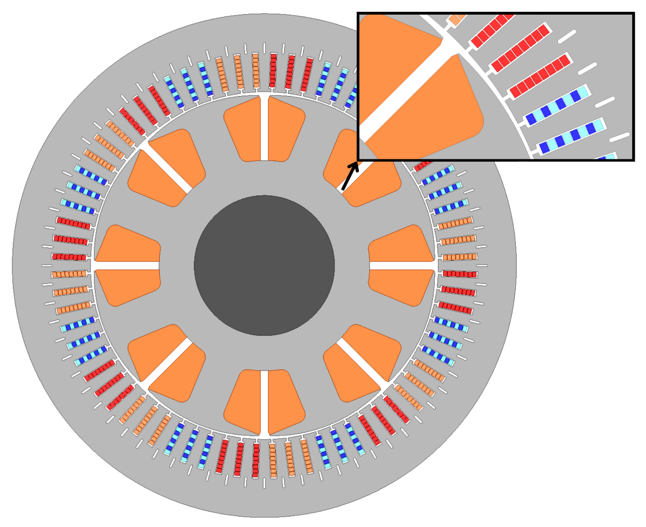
Figure 1 shows the cross-section view of the EESM designed for a propulsion application. It is designed to achieve a peak torque of 350 Nm and a peak power of 160 kW. It has a 72-slot eight-pole configuration. The maximum speed of the electric motor is 20,000 rpm. The stator outer diameter is 230 mm and the stator stack length is 90 mm. The power density of the EESM is 42.9 kW/L. It is designed for a peak current density of 32 A/mm2 on the stator coils. The rotor current is 19.91 A for the maximum torque and it starts reducing after 10,000 rpm for flux weakening. For the maximum torque at the maximum speed, the rotor current is 16.65 A.
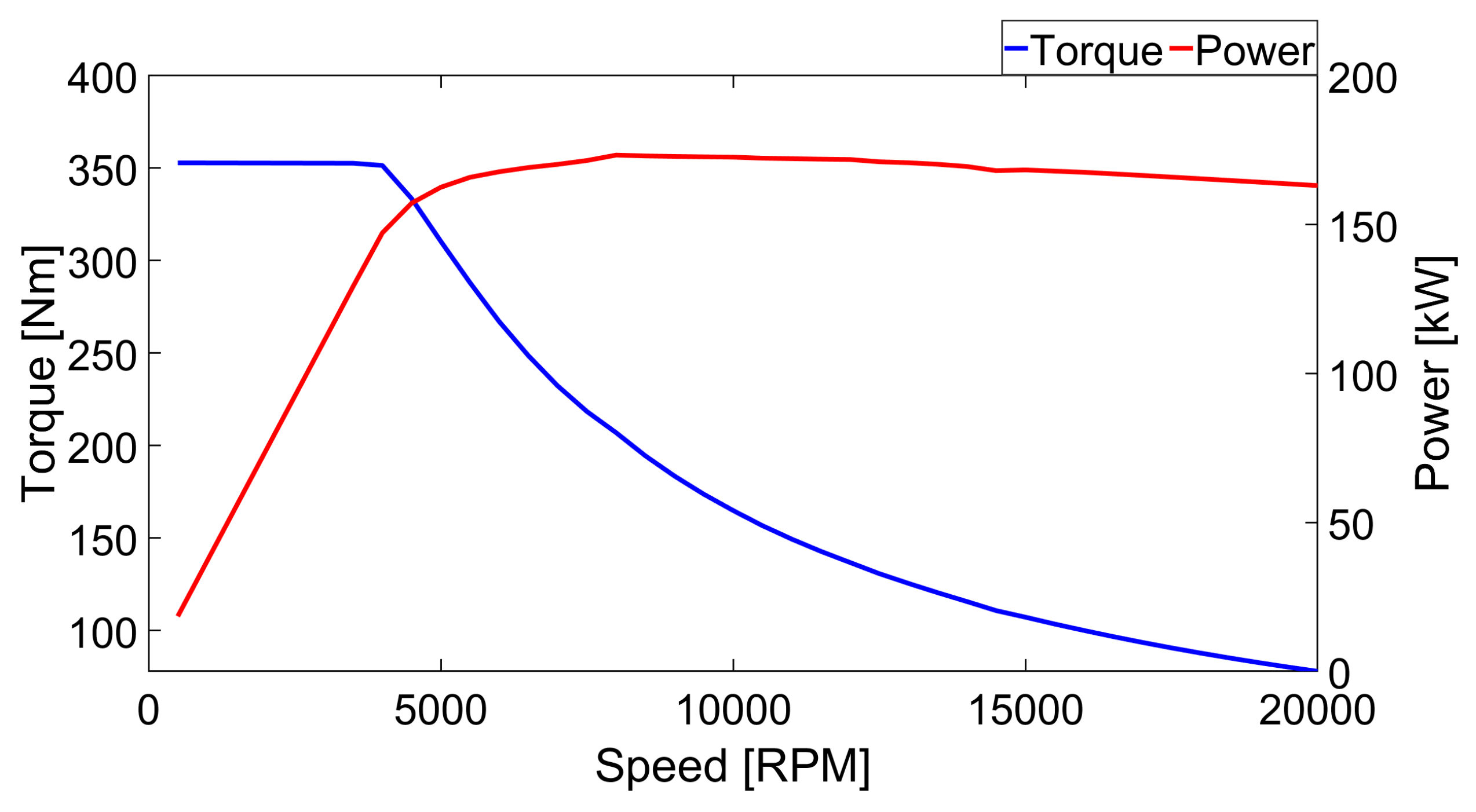
Figure 2 presents the torque-speed and power-speed curves of the designed EESM, which is referred to as the base design throughout the manuscript. The electric motor is designed to deliver 356.19 Nm of torque up to 4400 rpm, which corresponds to 160 kW of peak power. In the constant torque region, the electric motor is controlled using a maximum torque per ampere (MTPA) strategy with a maximum modulation index of one.
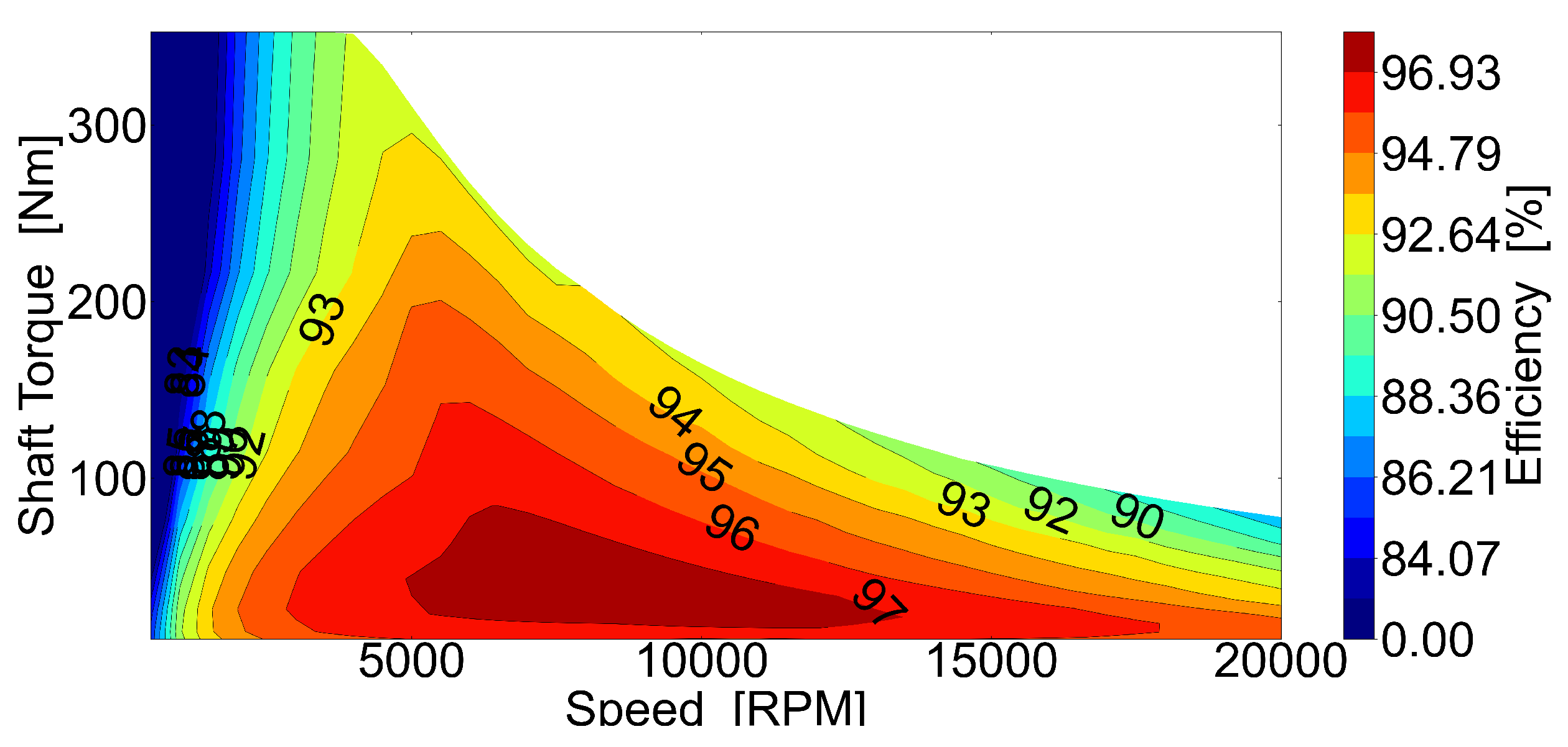
Figure 3 shows the efficiency map of the base EESM design. At 10,000 rpm, the electric motor achieves a maximum efficiency of 97.74%. A lower rotor current contributes to improving the efficiency at high speeds. The rotor current is optimized as a function of speed to reduce electromagnetic losses. However, at high speeds, AC copper losses in the hairpin stator winding dominate [40]. At 20,000 rpm, the AC copper loss exceeds both the DC copper loss and iron losses, resulting in a 92.5% efficiency.
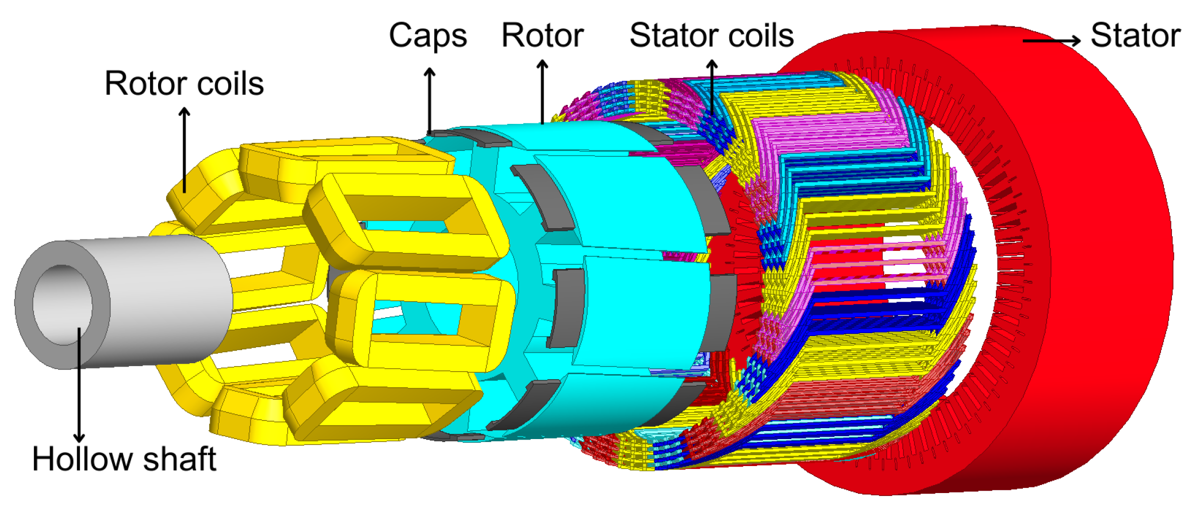
Figure 4 shows an exploded view of the base EESM design. The end caps support the rotor coils against centrifugal forces and prevent oil leakage into the airgap. The stator core includes microchannels to extract the heat from the stator coils.

3. Proposed Cooling Method

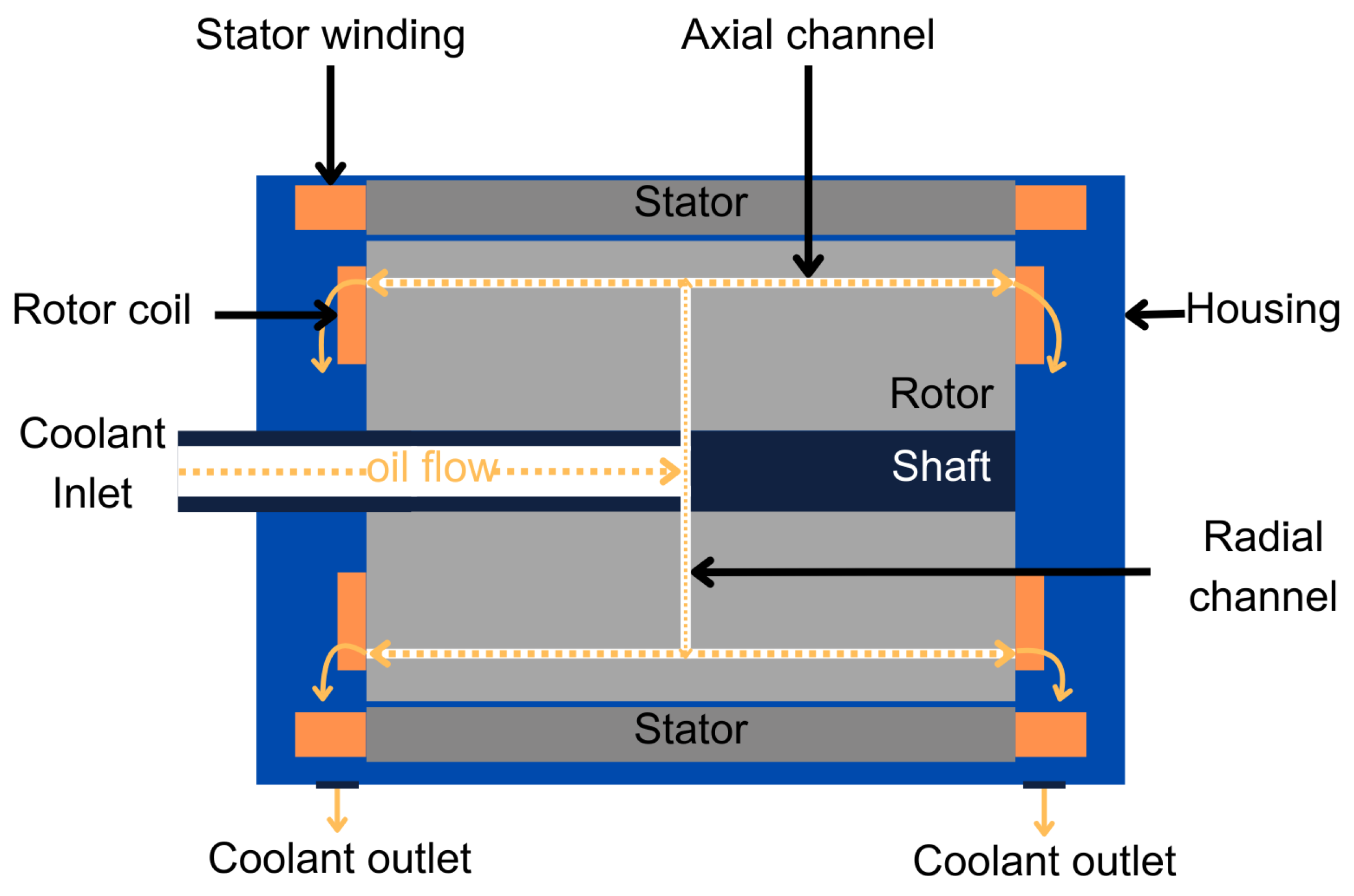
To maintain a high rotor current density in the designed EESM, conventional cooling methods might not be sufficient, as they do not directly extract heat from the rotor coils [27]. The proposed rotor cooling method is designed for direct cooling of the rotor coils. Figure 5 shows the functional diagram of the proposed cooling concept. It includes a hollow shaft as the primary conduit. Ultra-low-viscosity, non-conductive automotive-grade oil is pumped into the rotor through the shaft.
At the midpoint of the rotor, oil moves radially outward through radial channels by the pressure from the pump, and centrifugal forces due to the rotation of the rotor. After radial distribution, oil flows through the axial channels embedded in the rotor laminations. The axial channels are positioned parallel to the longitudinal axis of the rotor. The axial channels, located near the rotor surface, enable direct coolant contact with rotor windings and help reduce the thermal resistance.
Axial channels spray oil onto the rotor end windings, targeting hotspots on the end turns. The axial channels are designed in close proximity to the coils to ensure an even distribution of the coolant when the oil is splashed onto the rotor coils. Oil is collected through coolant outlets.

4. Location and Shape of Axial Channels

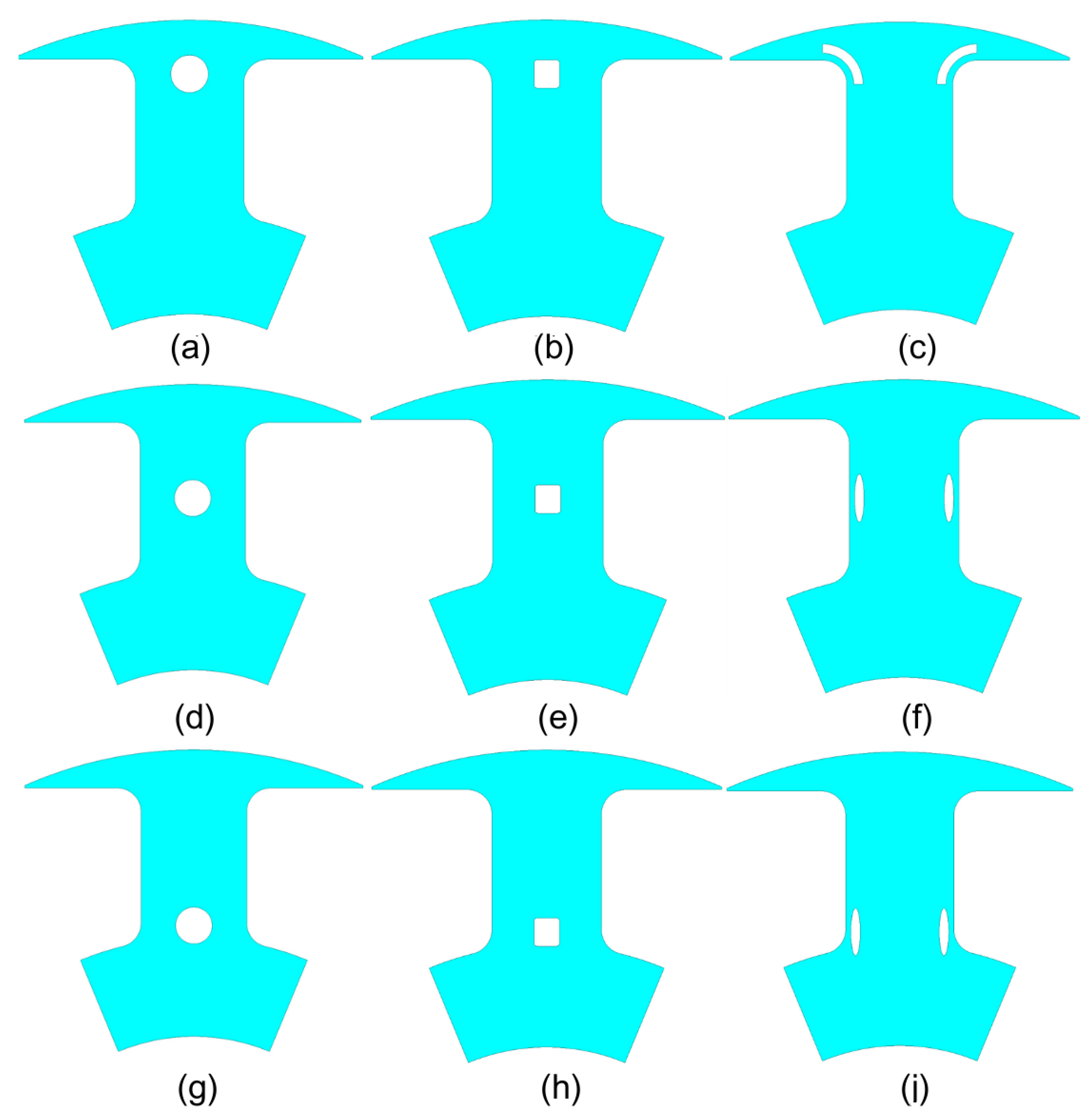
The oil channels in the rotor core introduce air gaps in the flux path. To maintain the electric motor performance and efficiency, the radial and axial channels should be designed in the proper shapes and sizes. The location and shape are the two main factors to consider when designing the axial channels. Figure 6 presents three different channel shapes that were considered (square, circular, elliptical) at three different locations.
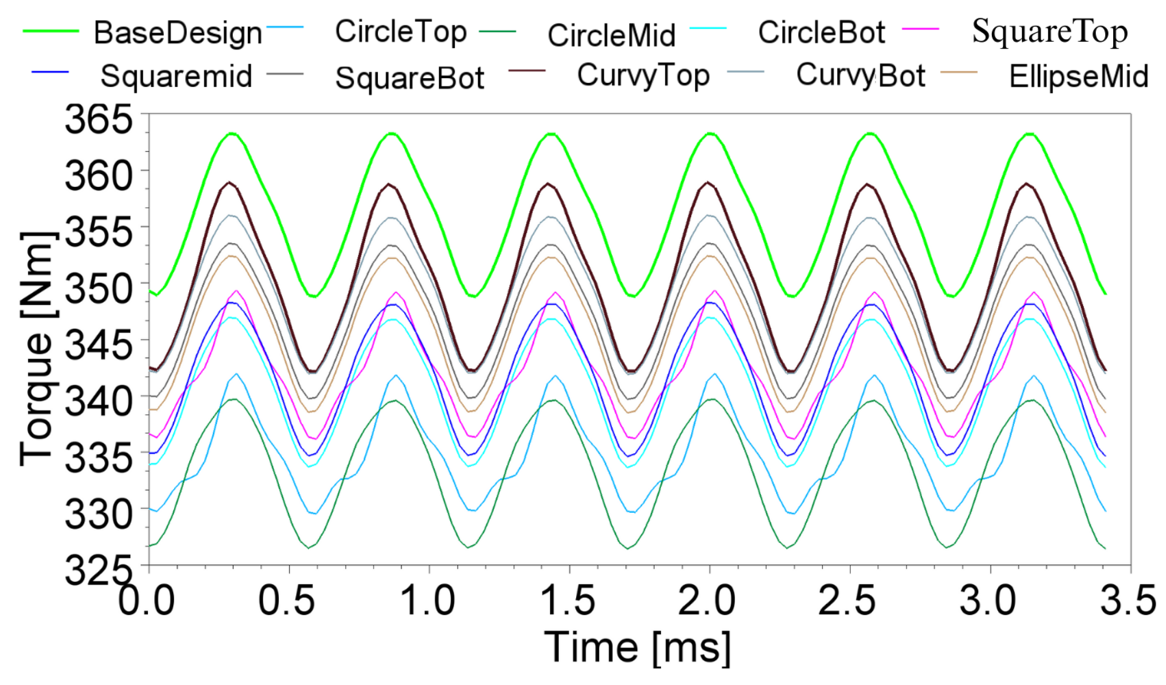
Figure 7 shows the torque waveform for different axial channel shapes for the peak torque operation at 4400 rpm. The stator current was 500 Arms, and the rotor current was 19.91 A. The waveforms were generated using a two-dimensional (2D) model in ANSYS Maxwell 2024R2. Table 1 quantifies the change in the average torque and torque ripple with the introduction of axial channels, and compares them with the base design without the cooling channels. The average torque dropped from 356.19 Nm to 333.28 Nm for the circular channel design, and to 341.92 Nm for the square channel design. The average torque with the circular and square channels was below the torque requirement for the propulsion EESM. The ellipse channel, positioned at the top side of the rotor pole in Figure 6c, achieved a 350.39 Nm average torque, which is 1.62% lower than the base design.
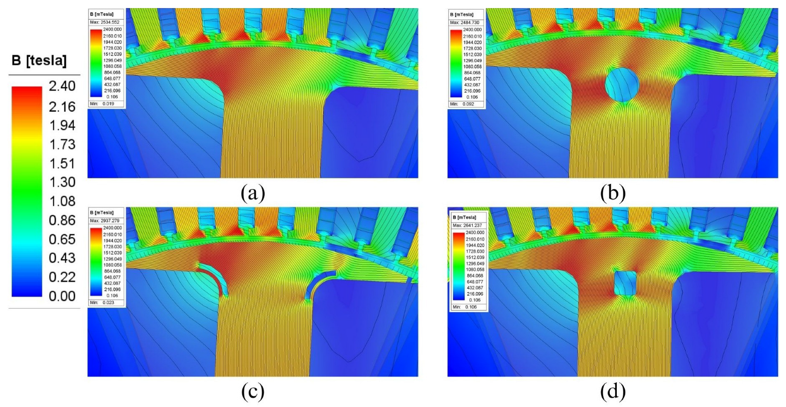
The primary reason for torque reduction was the change in the flux distribution when the channels were introduced. Local saturation occurred around the circular and square channels, as shown in Figure 8b and Figure 8d, respectively. The magnetic flux density level exceeded the saturation point of the rotor lamination material, NO25 [41]. The ellipse channels in Figure 8c were designed to follow the flux path of the base design in Figure 8a from the rotor tip to the rotor body. Hence, the change in the flux density distribution was small. In addition, the ellipse channels were located on both sides of the rotor, which reduced the impact to the flux path.

5. Multi-Physic Optimization of the Axial Channels

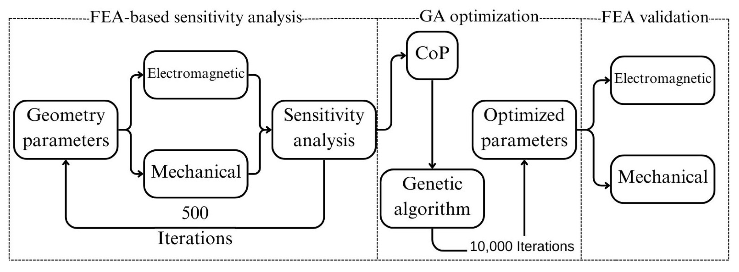
Axial channels in an ellipse shape located at the top of the rotor had the smallest impact on the electromagnetic torque. A further optimization process was still required to minimize the impact of the channels on the electromagnetic performance and maximize the cross-sectional area of the channels to enhance the oil flow. Figure 9 shows the multi-physics optimization workflow for the axial channels. A sensitivity analysis was first conducted using electromagnetic and mechanical FEA in ANSYS. A contribution of parameter (CoP) matrix was generated to identify which parameter had the largest impact on the optimization objectives [42]. A total of 500 different geometries were evaluated using ANSYS optiSlang 2024R2 to build the CoP matrix. Then, the CoP results were used in a genetic algorithm (GA) optimization to find the optimized parameters. In total, 10,000 iterations were completed using GA optimization. Finally, the optimized parameters were applied to the FEA model and the result of the optimization was validated through FEA.
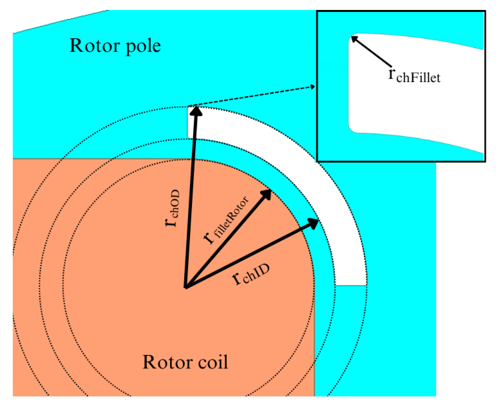
Figure 10 shows the optimization parameters for the axial channel geometry. The center of the inner and outer diameters of the elliptical channels were aligned with the center of the rotor top fillet. This ensured symmetry and uniformity between the rotor fillet and the oil channel. Another fillet was applied to the corners of the channels to reduce the interaction with the flux path. Table 2 shows the ranges for the optimization parameters and constraints. The objective of the optimization was to maximize the cross-sectional area of the axial channels. The average torque was constrained at 350 Nm and the maximum torque ripple was constrained at 5%. A design constraint was imposed to ensure that the cooling channels had a minimum cross-sectional area of 4 mm2 to avoid a potential case during the optimization where channels are removed.
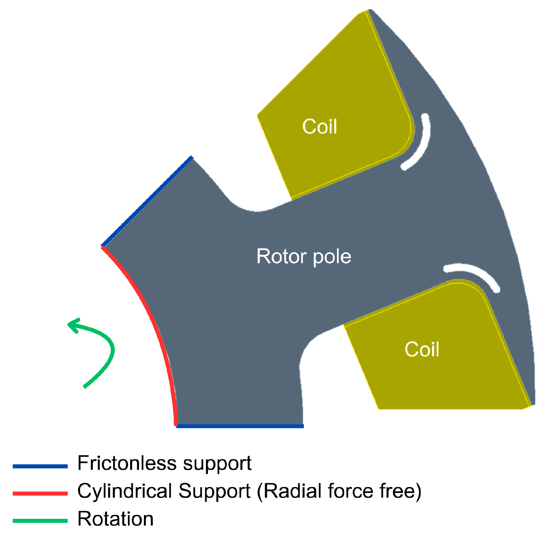
For the structural integrity of the rotor, the impact of the channels on the mechanical stress was considered in the optimization. The maximum Von Mises stress was limited below 420 MPa, which corresponds to the yield strength of NO25 lamination material [41]. Figure 11 shows the boundary conditions applied in the mechanical FEA model. Frictionless support was applied at the symmetry points of the rotor. A cylindrical support was used to constrain tangential motion while allowing radial freedom. The coils were modeled as copper blocks. The bottom parts of the coils were trimmed to simulate a scenario, where centrifugal forces push the coils toward the rotor tip. The effective material density of copper was multiplied by 0.7 to represent the slot fill factor.
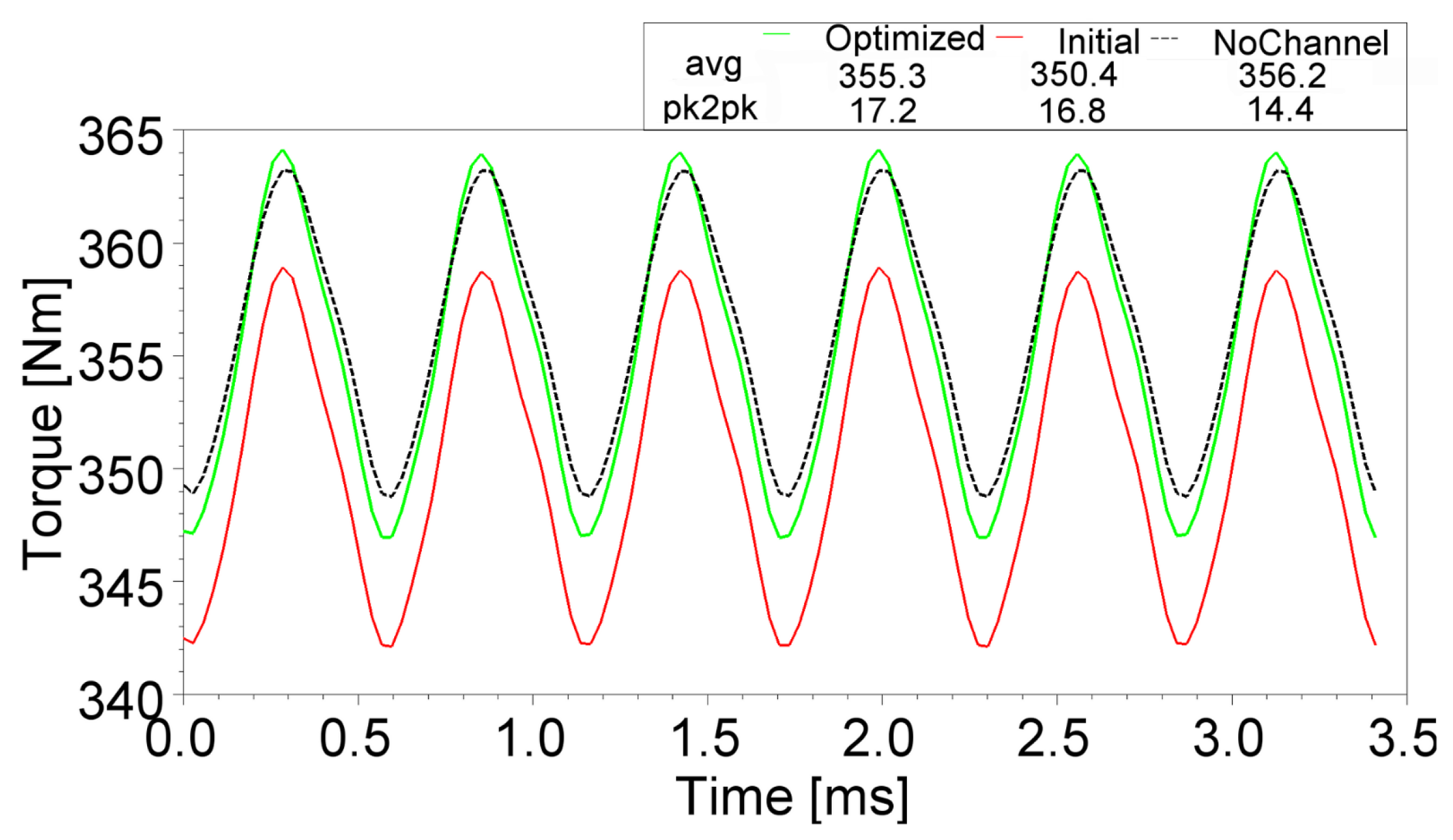
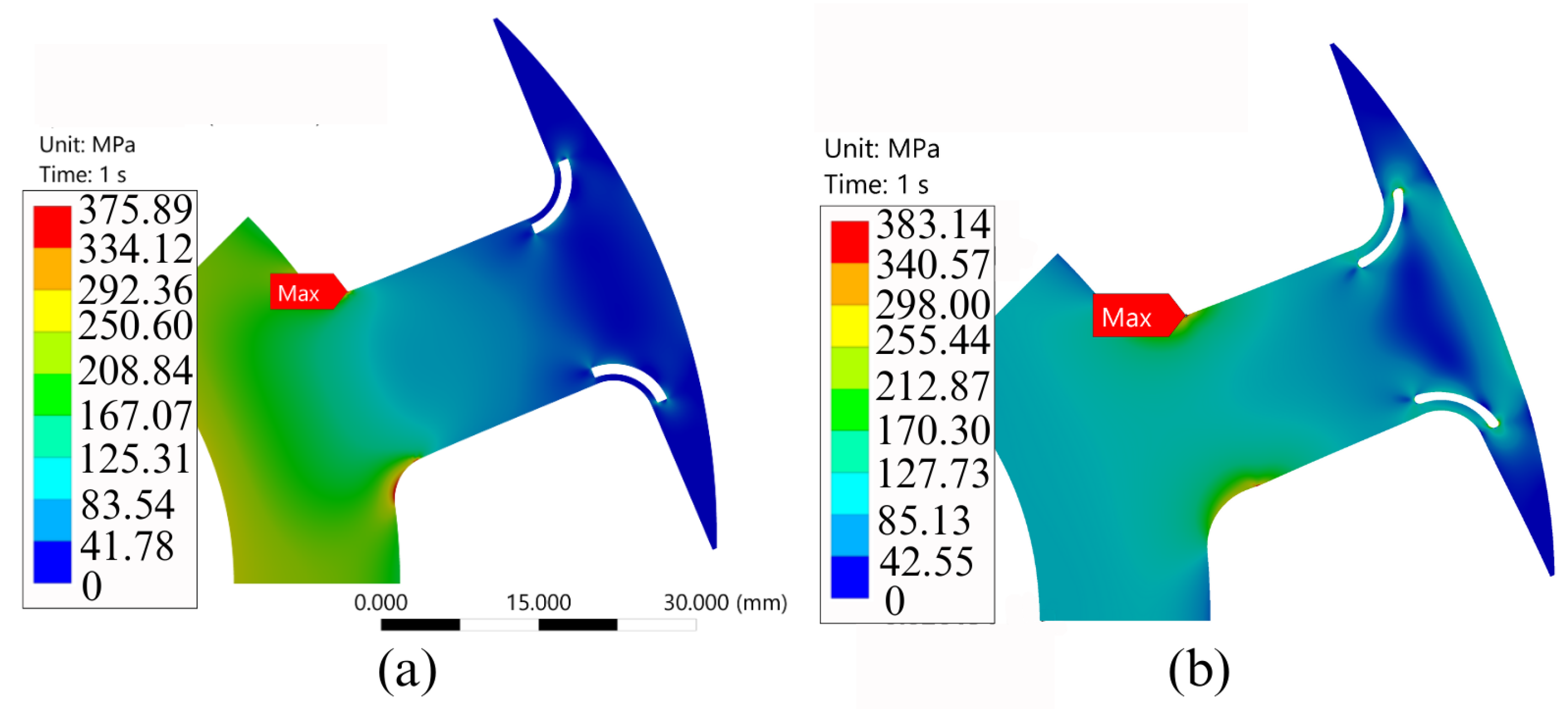
Table 3 shows the sensitivity of the optimization objectives to the optimization parameters. The channel outer diameter contributed 34.53% to the average torque, while the channel fillet contributed only 2.42%. The channel fillet had a small influence on the rotor stress, as it helped reduce the stress concentration by rounding the channel corners. Figure 12 shows the torque waveforms of the base design with no channel, the initial channel design, and the optimized channel design. Table 4 presents the optimization results. With the optimized axial channels, the average torque increased by 2.5%, and the torque ripple increased by 1.2% compared to the base design. The design here is referred to as the Stage 1 optimized design. The torque ripple increased by 1.2% compared to the base design. As shown in Figure 13, the Von Mises stress remained below the yield strength, with a maximum value of 383.14 MPa. The channel area for each duct increased by 10%. The increase in the cross-sectional area of the axial channels would help improve the coolant flow, and it did not compromise the electromagnetic or mechanical performance compared to the base design.

6. Design of the Radial Channels

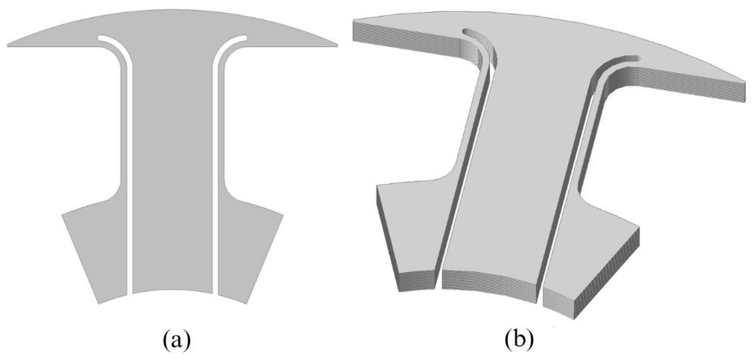
As shown in Figure 5, implementing radial channels requires an additional lamination geometry distinct from the main rotor lamination. This specific lamination integrates both the radial and axial channels and is placed at the axial center of the rotor. The radial channels are positioned at this central region. As shown in Figure 14, the radial channels extend outward from the hollow shaft towards the outer circumference of the rotor. The number of laminations with the radial channel geometry defines the depth of the radial channels. The radial channels transfer the oil in the hollow shaft to the axial channels to apply coolant onto the rotor coils.
Figure 14a shows the rectangular-shaped radial channels on each side of the rotor pole. The radial channels extend directly from the hollow shaft to the axial channels. To ensure a continuous oil passage, the radial channels are aligned with the holes on the outer surface of the rotor.
As shown in Figure 5, the radial channels are located at the center of the rotor in the axial direction. The flux passing through the rotor core along the axial center where the radial channels are located would encounter a higher reluctance due the airgap from the radial channels. To reduce this effect, the axial length of the radial channels should be kept as small as possible. At the same time, sufficient clearance should be maintained for oil transfer from the hollow shaft to the axial channels.
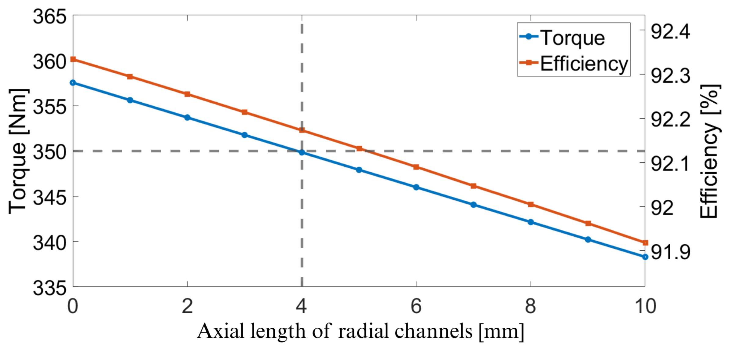
An iterative study was conducted to evaluate the impact of the axial length of the radial channels on the electromagnetic performance. Figure 15 shows the electromagnetic torque and efficiency as a function of the radial channel thickness using 3D FEA simulations. A radial channel thickness of 4 mm achieved 350.1 Nm of average torque and a 92.17% efficiency. The design achieved after radial channel optimization is referred to as the Stage 2 optimized design. Each NO25 rotor lamination was 0.25 mm thick. Therefore, the radial channels were created by stacking 16 laminations at the center of the rotor.
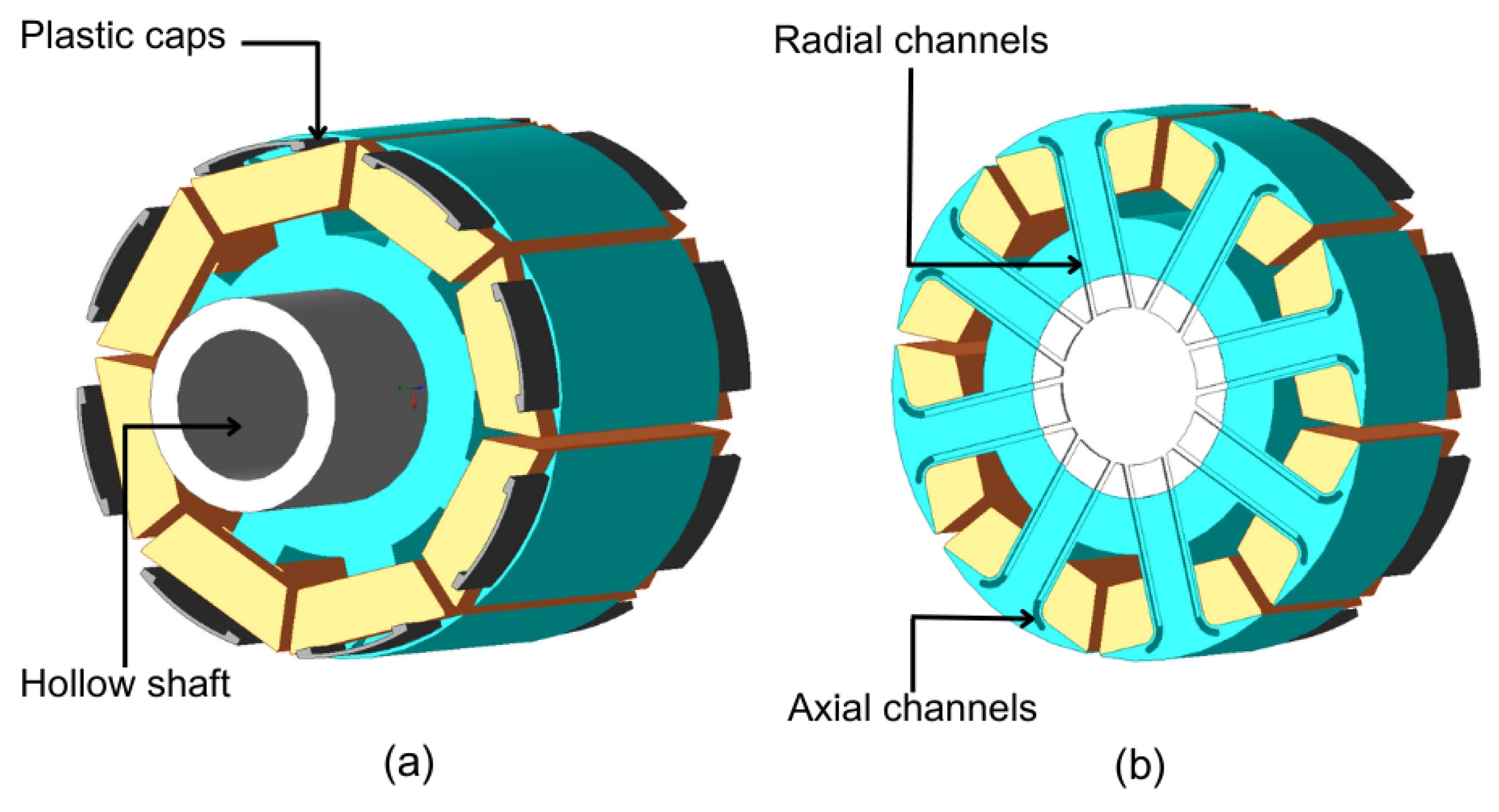
Figure 16a shows the 3D model of the EESM rotor. The rotor coils are represented with a modified geometry to show the channels clearly. As shown in Figure 16a, plastic caps covered the space between the end turns of the rotor coils and the rotor poles. These caps helped channel the oil splashed from the axial channels towards the end turns. They also provided structural support for the retention of the rotor coils. Figure 16b shows the cross-section of the rotor at the center and depicts how the radial and axial channels were connected to the hollow shaft.
The rotor laminations will be fabricated using laser cutting, a widely adopted manufacturing process for electrical machine laminations [43,44], as it produces assembly-ready components with minimal post-processing requirements [45]. Due to the incorporation of the proposed axial and radial cooling channels, the laminations will be sorted and assembled in a predefined sequence after cutting to ensure proper alignment and facilitate the rotor-stacking process. The caps will be fabricated using glass-fiber-reinforced plastics (GFRPs) and can operate at temperatures up to 160 °C [46,47]. The caps will be mounted on the stator using the cooling slots and TA4590 adhesive, which can withstand high temperatures [48,49].

7. Analysis of Thermal Performance with Computational Fluid Dynamics

Steady-state CFD simulations were performed to assess the thermal performance of the proposed direct rotor oil cooling method under continuous operating conditions. Both the stationary and rotating states of the rotor were modeled to evaluate the effect of centrifugal forces on the oil distribution. The simulations also accounted for heat fluxes generated by copper and iron losses, allowing for an estimation of the steady-state temperatures.
Our previous work provides detailed discussions on key aspects of CFD modeling, including the mesh requirements, wall treatment strategies, fluid–solid heat transfer modeling, and mesh convergence assessment [50]. An unstructured conformal mesh strategy was employed in this study to significantly reduce the computational requirements. The generated mesh consisted of tetrahedral, hexahedral, and arbitrary polyhedral elements, enabling semi-automated mesh generation while maintaining flexibility for complex geometries. Furthermore, this approach facilitated the accurate resolution of boundary-layer effects through the use of high-aspect-ratio prism cells [51]. The shear stress transport (SST) turbulence model was adopted for the simulations. The SST model combines the advantages of the k- ω and k- ε formulations and incorporates a shear-stress limiter to improve the prediction accuracy, particularly by mitigating the excessive turbulence generation commonly associated with conventional k- ω and k- ε models [52]. The adequacy and convergence of the numerical solution were assessed using the residual histories obtained from ANSYS CFD [53]. Convergence was considered achieved when the residuals exhibited a consistent decreasing trend and eventually reached a stable value, with particular attention given to the continuity residual to ensure mass conservation. To assess the influence of the mesh density on the numerical results, a mesh convergence study was performed by systematically refining the computational mesh. Successive simulations were conducted with increasing mesh densities until further refinement resulted in negligible variations in the predicted quantities of interest, indicating that mesh-independent solutions had been achieved.

7.1. Boundary Conditions

Table 5 shows the material properties used in the CFD simulations and Table 6 presents the properties of the coolant considered for the direct rotor cooling concept [54]. The rotor and stator cores were made from NO25 electrical steel laminations. The stator and rotor coils were made of copper. AISI 8620 steel was selected for the shaft. Priolube oil, which has a low thermal conductivity and high specific heat coefficients, was used for the fluid region.
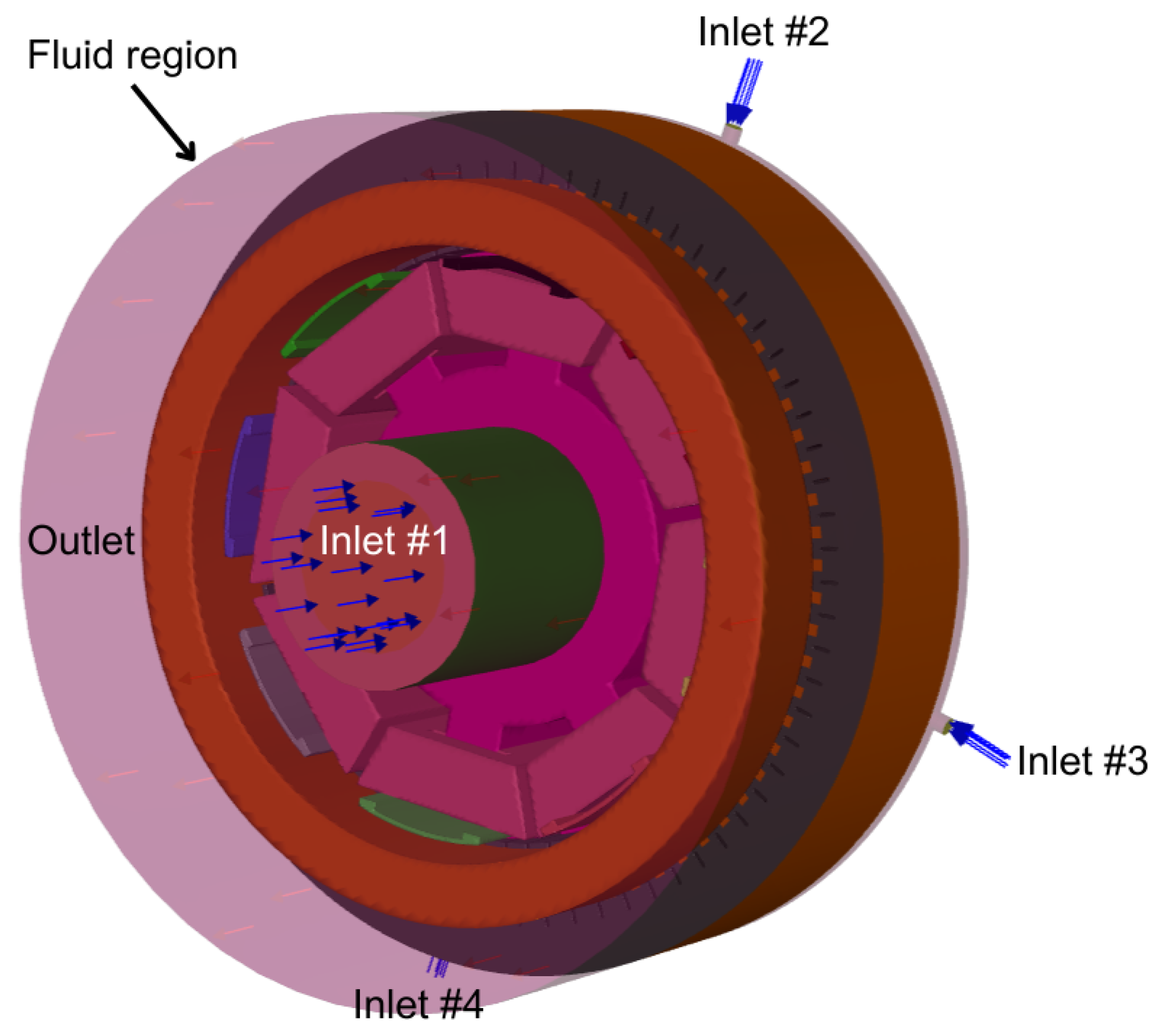
Figure 17 shows the boundary conditions of the CFD model. A fluid region was defined to represent the internal volume of the housing, including both the oil and air domains. Four inlets were modeled to introduce the fluid to the system. Inlet #1 in Figure 17 is through the hollow shaft and it provides the coolant into the rotor. The remaining three inlets represent the stator microchannels [56]. These channels direct the coolant towards the center of the stator and enable oil splash cooling for the stator windings. To reduce the computational time, the front face of the fluid region was assigned as the outlet instead of the drain holes at the bottom. Only one axial half of the motor was modeled to reduce the model size and simulation time.
The inlet velocity determines the speed at which the coolant enters the system. As shown in (1), the inlet velocity, v, is calculated by dividing the flow rate, Q, by the inlet surface area, A. The surface area of Inlet #1 was 1582.5 mm2 The combined surface area of Inlets #2–4 was 58.89 mm2 The rotor inlet velocity was 0.0527 m/s. The velocity at each stator inlet was 1.415 m/s. The outlet was where the oil was sucked out of the system; hence, it was defined as a zero-pressure outlet.
v = Q A ,
The heat fluxes for each component of the EESM were determined based on the losses under different operating conditions and the volume of the component. The stator coil volume was 384.90 cm3, the rotor coil volume was 584.30 cm3, and the stator core volume was 1551.60 cm3. Table 7 shows the data points used in the steady-state CFD simulations. Continuous and light-loading conditions at different speeds were considered for the steady-state CFD analysis.

7.2. Stationary and Rotational Rotor

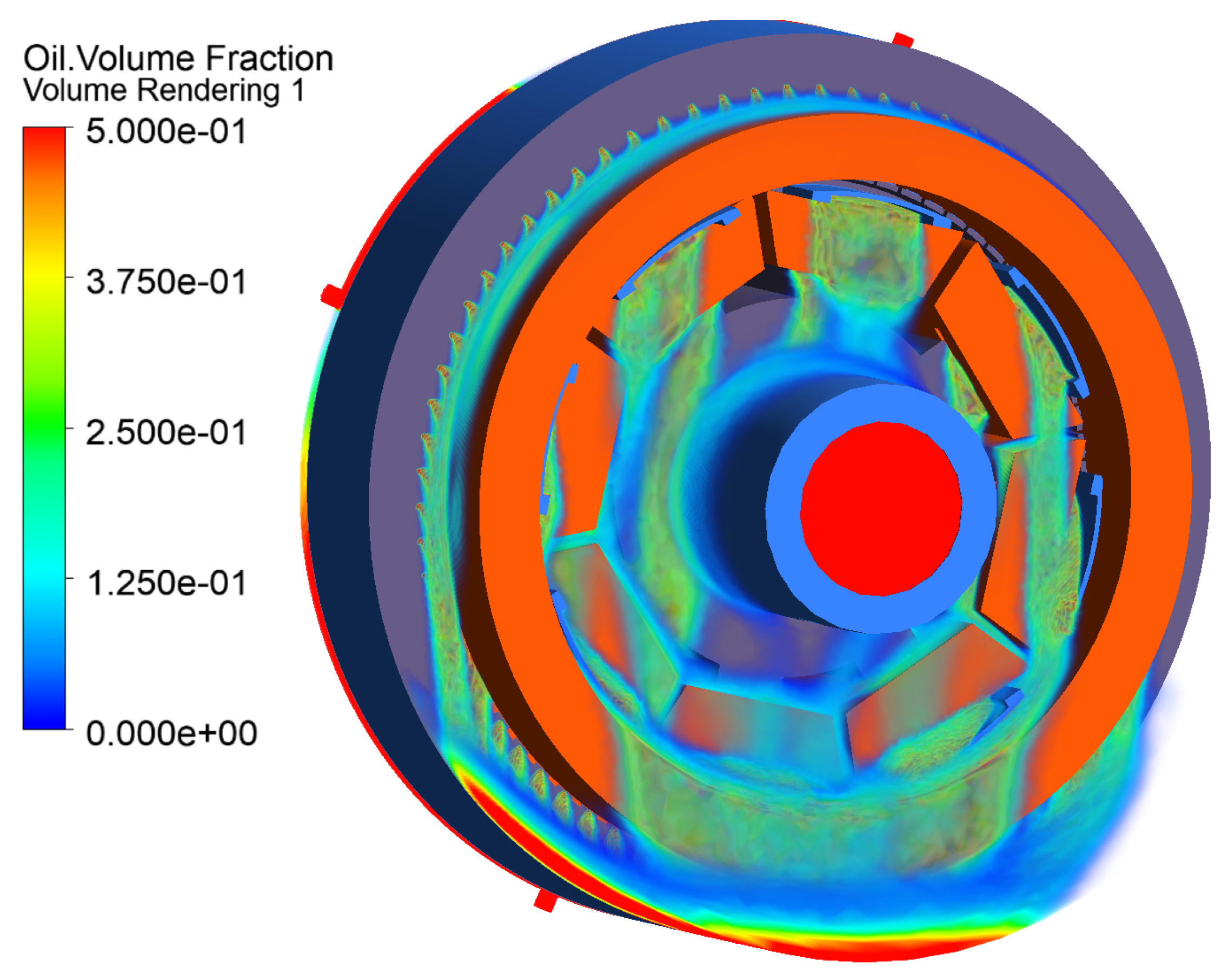
In the CFD model, the rotor and coils are set to rotate together. Simulating oil flow requires the consideration of centrifugal forces resulting from the rotation. Figure 18 shows the volume fraction of oil under the influence of gravity along the negative y-axis. This illustrates the stationary rotor oil flow. Due to the relatively low oil velocity, the oil accumulates directly on the motor housing.
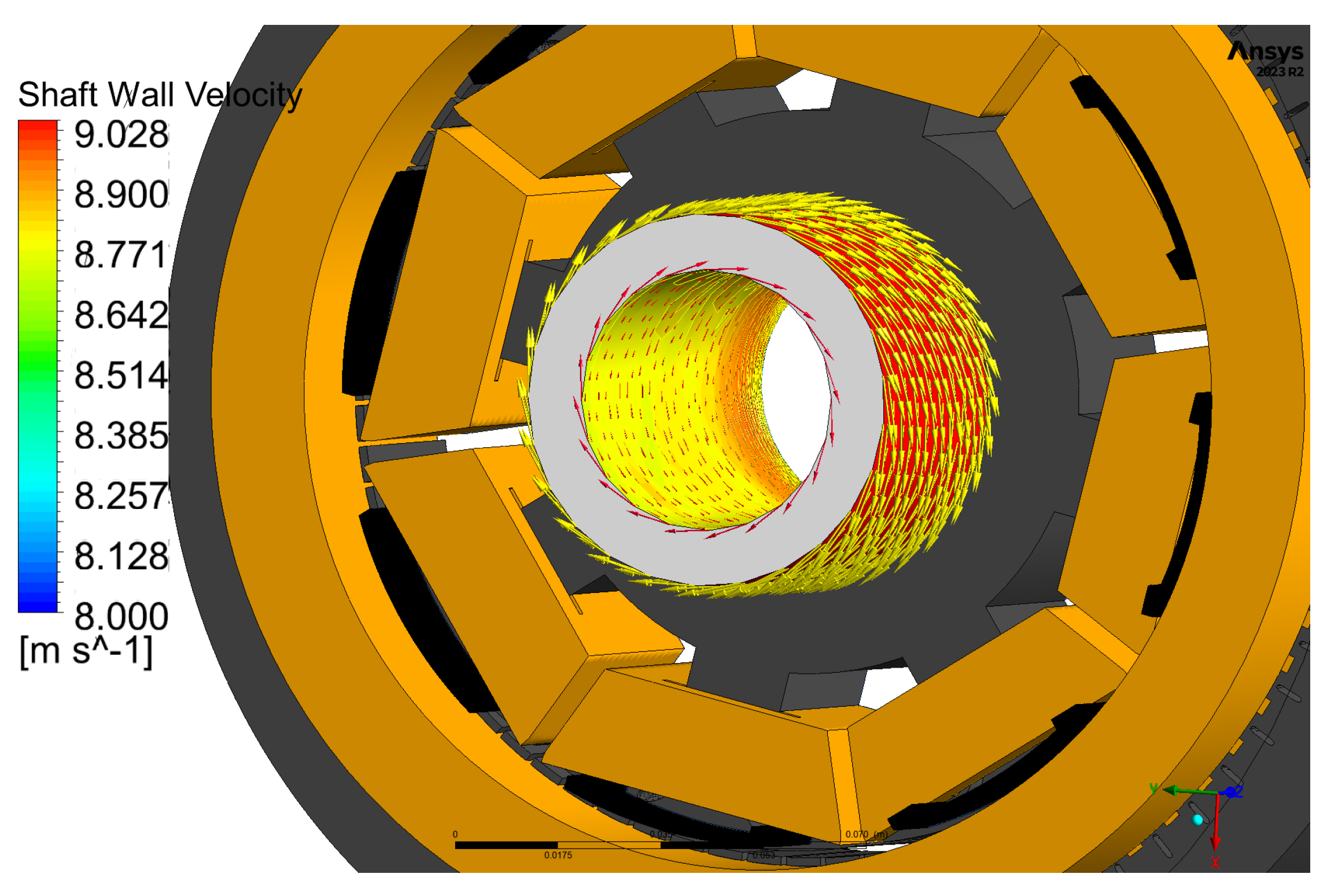
Once the rotor begins to rotate, centrifugal forces act on the oil. The oil acquires a tangential velocity along the inner wall of the shaft. This tangential velocity is calculated using (2), where ω is the angular velocity and R is the radius of the shaft. The angular velocity, ω , is calculated from the rotational speed, N, using (3).
V tangential = ω R ,
ω = 2 π N 60 ,
The shaft’s inner radius is 21.4 mm. At 4000 rpm, the tangential velocity should be 8.96 m/s at the shaft inner wall. For validation, a CFD simulation was performed with the rotor rotating at 4000 rpm. Figure 19 illustrates the tangential velocity distribution on the inner wall of the shaft. The maximum tangential velocity is 8.97 m/s, and it closely matches the analytical calculation.
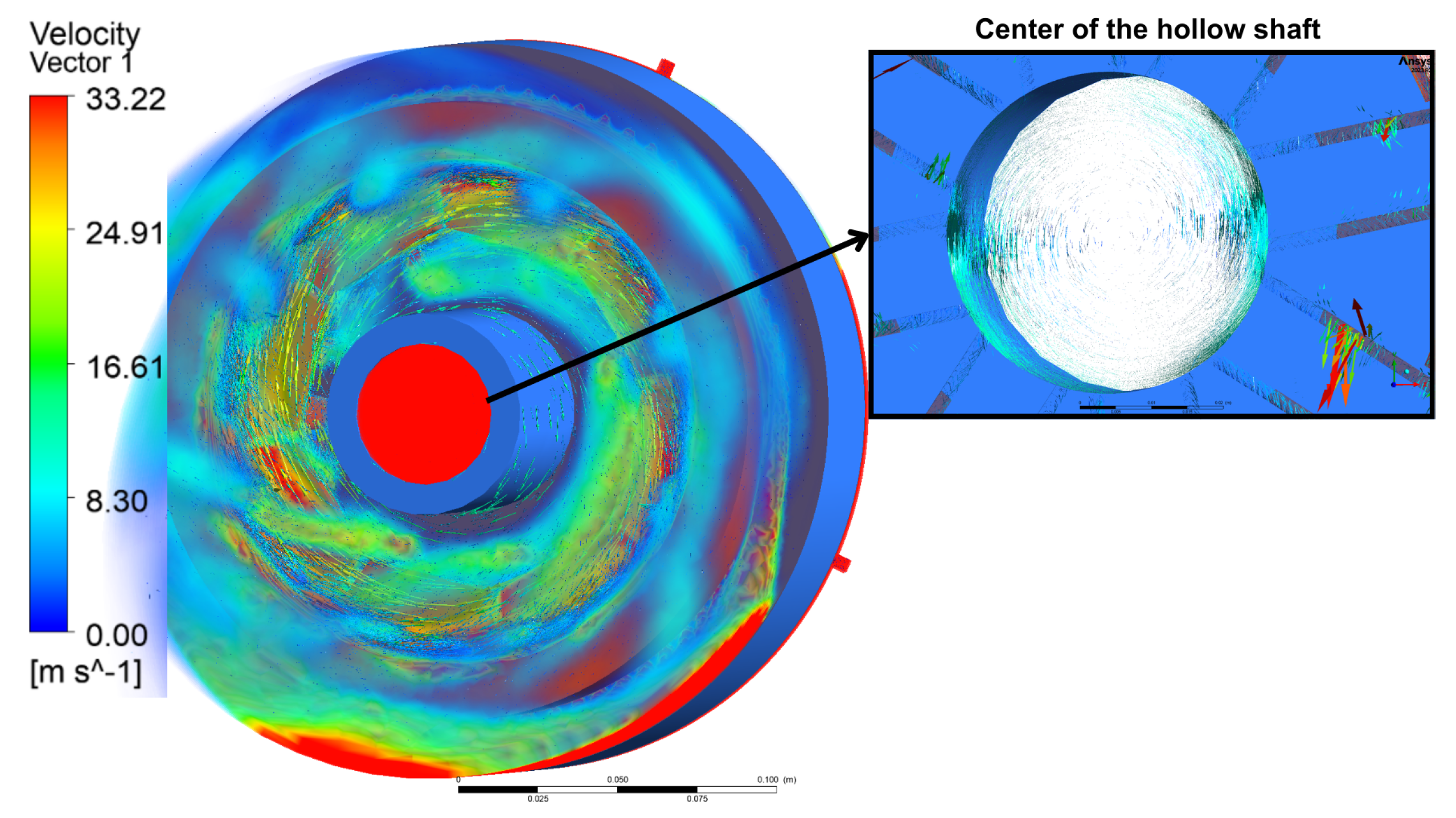
Figure 20 shows that, when the electric motor rotates at 4000 RPM, the fluid reaches the end of the hollow shaft. As depicted in Figure 5, the hollow shaft ends at the center of the rotor where the radial channels are located. Centrifugal forces propel the oil into the radial channels. The flow then directs the oil from the radial channels into the axial channels. At higher speeds, the centrifugal forces are larger. This drives more oil into the axial channels and generates a bigger spray effect that disperses the oil onto the rotor coils. The rotating oil then splashes against the plastic caps and rotor end windings before eventually settling at the bottom of the electric motor housing, where it is collected and drained through the outlet.

8. Temperature Maps from Computational Fluid Dynamics Simulation

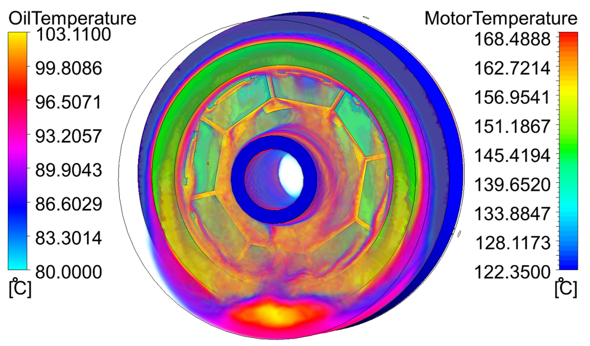
Initial thermal analyses were conducted at 210 Nm and 0 rpm and at 210 Nm and 4000 rpm with an inlet oil temperature of 80 °C to observe the temperature distribution of the EESM at different speeds. Figure 21 shows that, when the rotor was stationary, the rotor coil temperature reached 132.2 °C at the hotspot located on the end turns. The maximum stator temperature was 160.67 °C. The oil temperature at the outlet was 103.11 °C.
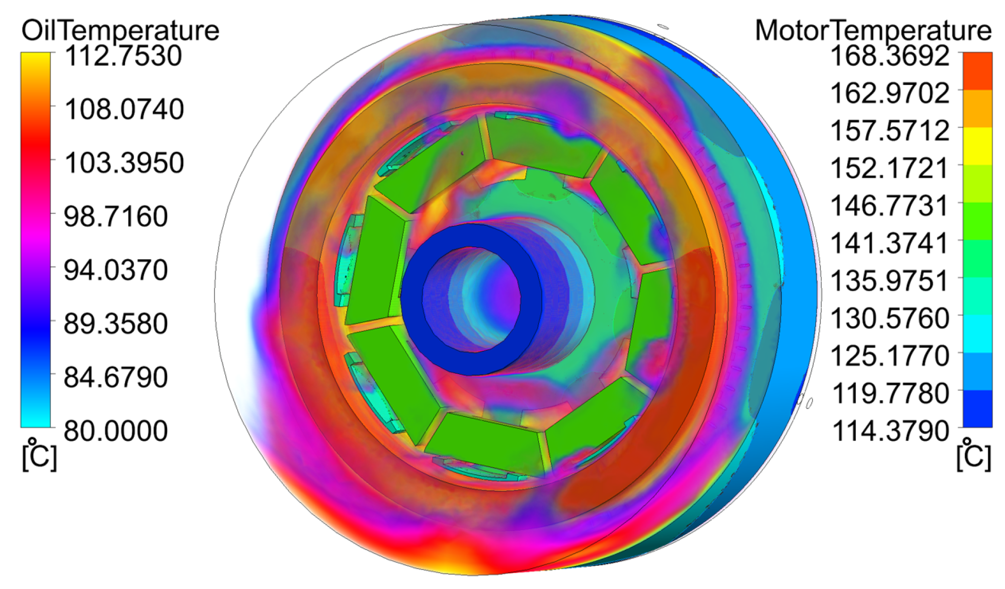
Figure 22 shows the effect of rotor rotation at 4000 rpm and 210 Nm. With the rotation, the spray-cooling effect was more efficient for the rotor coils. The steady-state rotor coil temperature dropped from 132.2 °C under the non-rotating condition in Figure 21 to 123.69 °C in Figure 22. The stator coil temperature dropped from 160.67 °C to 154.99 °C. With the rotating splashing effect, the rotor oil was dispersed around the housing and onto the stator coils.
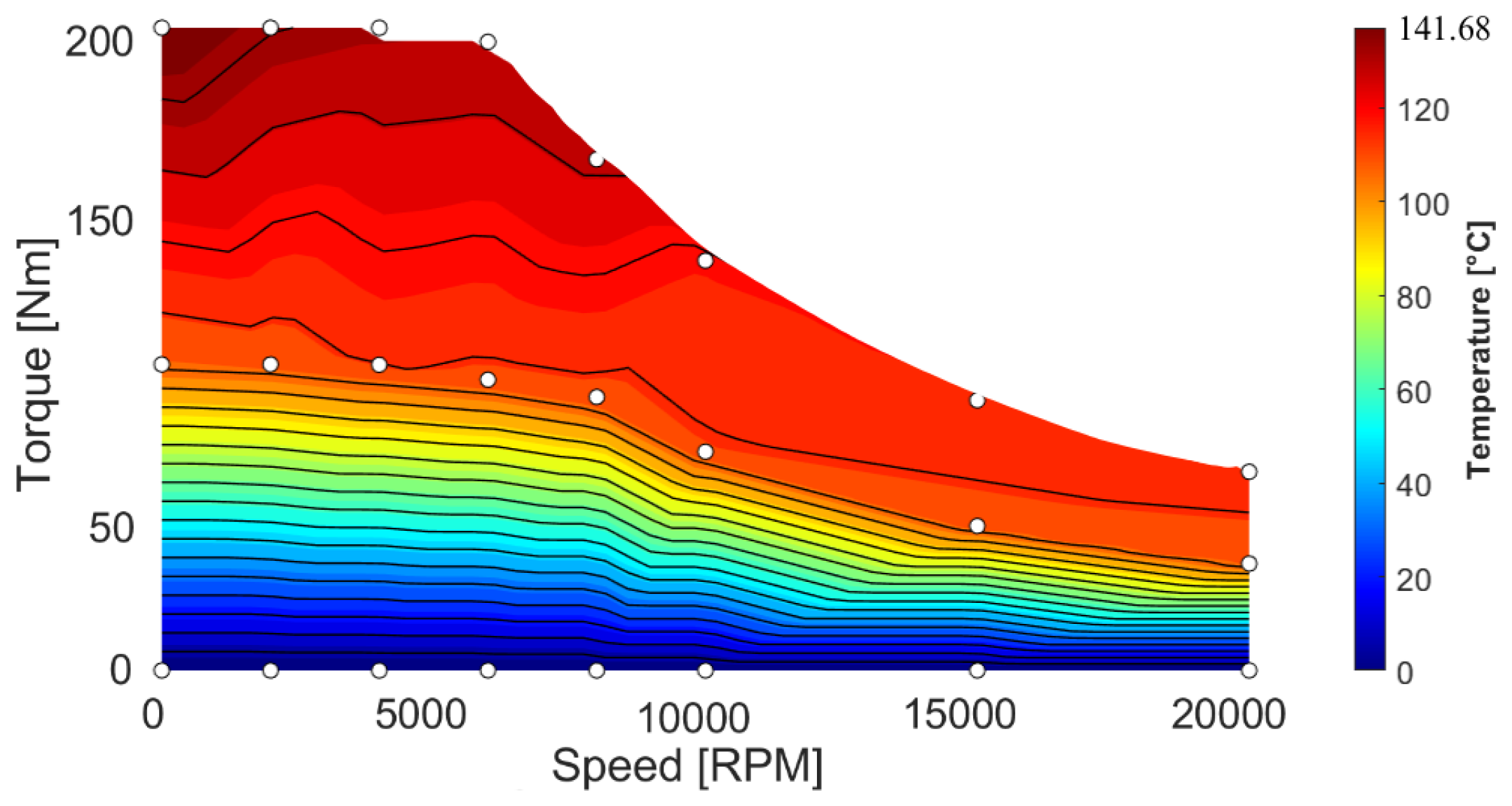
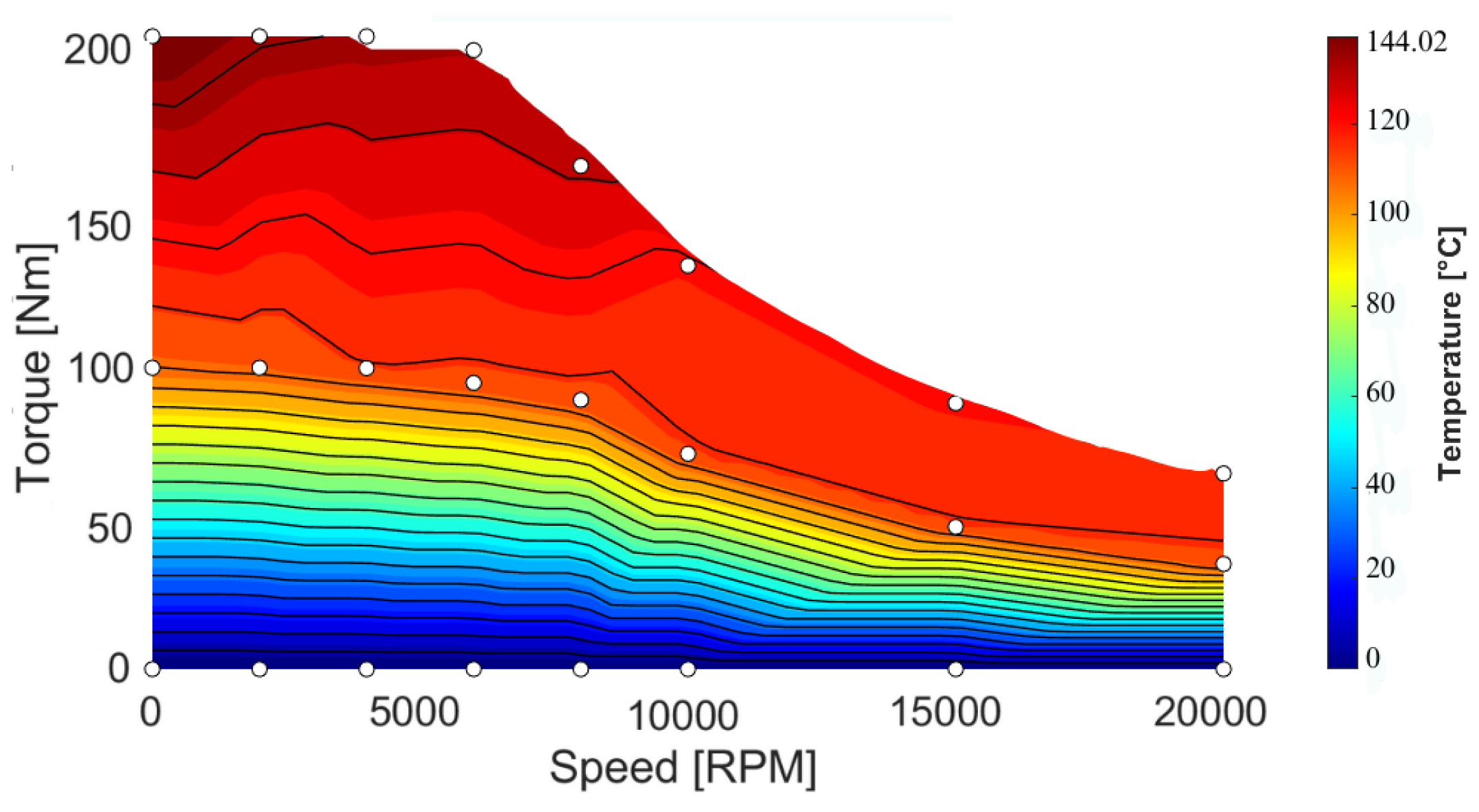
Temperature contour plots were generated using the CFD analysis to validate the effectiveness of the proposed cooling concept. The operating points in Table 7 for two different loading conditions were used. The resulting temperatures were then linearly interpolated in MATLAB 2024 to create a temperature contour map.
Figure 23 shows the average rotor coil temperature at a steady state. At 0 rpm, the steady-state rotor coil temperature was 141.68 °C, which decreased to 132.4 °C at 4400 rpm. At higher speeds, the spray effect became stronger, resulting in further reductions in the rotor coil temperature. This demonstrates an enhanced cooling performance due to the centrifugal forces acting on the coolant within the rotor. However, the rate of temperature reduction became less pronounced beyond 10,000 rpm, with only a marginal decrease observed between 10,000 and 20,000 rpm. This trend suggests that the cooling enhancement begins to approach a saturation region, where further increases in the rotational speed provide diminishing improvements in heat removal. The observed behavior may be attributed to a balance between the enhanced convective cooling resulting from stronger centrifugal action and the thermal losses generated under high-speed operation.
Figure 24 shows the maximum rotor coil temperature map at a steady state. The maximum rotor coil temperature was 144.02 °C at 0 rpm. It decreased to 136.5 °C at 4400 rpm. The small difference between the maximum and average temperatures shows that the proposed method achieved an evenly distributed heat extraction. Typically, the end turns experienced a higher temperature than the coil sides inside the slots [57]. The proposed cooling system applies the coolant directly onto the rotor coils and reduces the temperature gradient.
The life expectancy of winding insulation decreases with increasing temperature, with the rate of degradation becoming significantly more pronounced above 100–115 °C [58]. Therefore, even a 6–7% reduction in the operating temperature at temperatures exceeding 130 °C can substantially extend the service life of the insulation.

9. Functional Validation of the Rotor Cooling Method

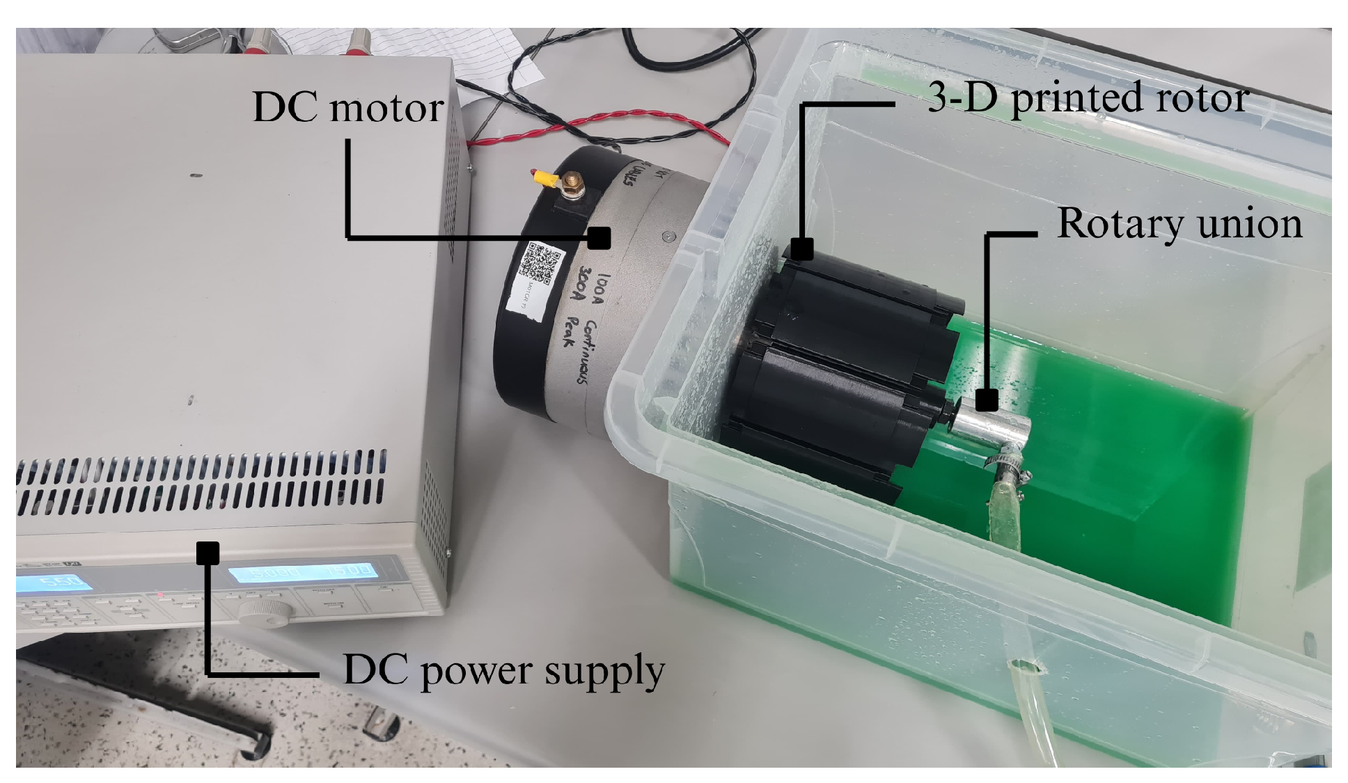
The proposed cooling method requires radial and axial channels to splash the coolant onto the end turns of the rotor coils. In order to validate whether the proposed concept works, an experimental setup was created for a functional validation of the proposed method, as shown in Figure 25. The rotor, with similar dimensions as the propulsion EESM design, was connected to a DC motor. The rotor speed was controlled by a DC power supply. A 3D-printed rotor was coupled to a submersible pump via a rotary union, which channeled the coolant to the hollow shaft. For validation of the coolant splash onto the end turns of the rotor coils and to improve the visibility of the flow, green-colored water was utilized.
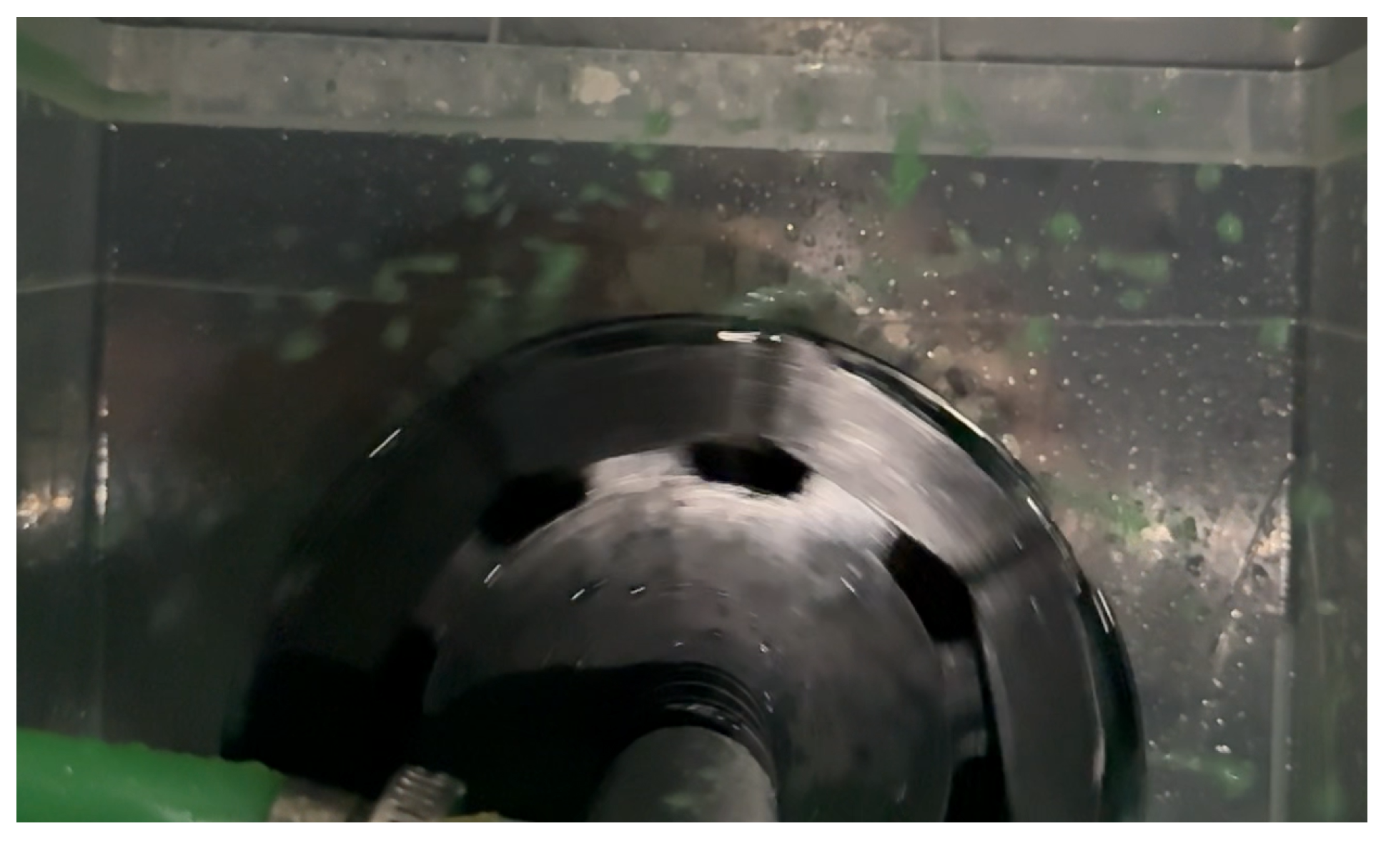
Figure 26 shows the coolant flow when the rotor rotates and the coolant is pumped into the hollow shaft. The coolant splashed onto the rotor coil. The plastic caps acted as a barrier to prevent the coolant from leaking onto the rotor surface. At higher rotational speeds, the coolant was pushed more into the channels and it was splashed into the rotor coils, as expected.

10. Conclusions

In this paper, a direct oil cooling concept for the rotor coils of an EESM is proposed. The proposed method utilizes a hollow shaft and integrated radial and axial channels to deliver ultra-low-viscosity, non-conductive oil directly onto the rotor coils.
The axial cooling channels are elliptical in shape and are positioned near the top surface of the rotor. Their dimensions were optimized through a multiphysics analysis to achieve an optimal balance between the cooling performance and the electromagnetic and structural integrity. The optimized Stage 1 design resulted in a substantial increase in the axial channel size while causing only a 0.24% reduction in the average torque compared with the baseline design. The maximum Von Mises stress on the rotor core was also maintained at 383.14 MPa, which is lower than the maximum stress limit of the rotor core material. In the Stage 2 optimized design, the radial channel diameter was optimized to 4 mm using a three-dimensional electromagnetic analysis. The optimized design resulted in only a 1.17% reduction in the average torque compared with the baseline design.
Computational fluid dynamics (CFD) simulations were conducted to validate the performance of the proposed cooling concept. At 4400 rpm, the average coil temperature at a steady state for continuous operation of the electric motor was 132.4 °C. At zero speed, the average rotor coil temperature was 141.68 °C. Therefore, the proposed method provides around a 6.5% reduction in temperature due to the proposed oil-splashing effect on the rotor coils. The maximum rotor coil temperature was 144.02 °C at zero speed and 136.5 °C at 4400 rpm. There was a small difference between the average and maximum rotor coil temperatures, which demonstrates that the proposed method achieved uniform cooling.
The operation of the proposed cooling method and the functionality of the radial and axial channels splashing oil on the rotor coils were validated with a functional setup and colored coolant. It was shown that the coolant reached the end turn of the rotor coils and the splashing effect improved as the speed increased.
The future scope of the current research includes prototype development and the validation of the thermal and electromagnetic performance to evaluate the effectiveness of the direct oil cooling method proposed in the manuscript. The prototype development will include an investigation of the manufacturing and assembly aspects of the rotor with the cooling channels. It will also investigate the material requirements of the caps, which help channel the oil splashed from the axial channels towards the end turns. The experimental evaluation will also include an investigation of the coolant flow rate through the hollow shaft.

Author Contributions

Conceptualization: B.S.Y.; Methodology: D.A.-A. and R.H.; Writing—Original Draft Preparation: J.D., A.K.S. and B.S.Y.; Writing—Review and Editing: Berker Bilgin; Supervision: D.A.-A., R.H. and B.B. All authors have read and agreed to the published version of the manuscript.

Funding

Funding was provided by the Natural Sciences and Engineering Council of Canada (NSERC) and Stellantis.

Data Availability Statement

The original contributions presented in this study are included in the article. Further inquiries can be directed to the corresponding author.

Acknowledgments

This research was undertaken in part thanks to funding from the Natural Sciences and Engineering Council of Canada (NSERC) and Stellantis. The authors would like to thank Prashant Modi from Stellantis for their technical support. The authors are also grateful to Rupayan Gosh and Gopal Uppalapati from the McMaster Automotive Resource Center (MARC) for the 3D printing for functional testing. The authors would also like to thank ANSYS for their support with the Workbench 2024R2 software.

Conflicts of Interest

The authors declare no conflicts of interest.

References

  1. Bilgin, B.; Magne, P.; Malysz, P.; Yang, Y.; Pantelic, V.; Preindl, M.; Korobkine, A.; Jiang, W.; Lawford, M.; Emadi, A. Making the case for electrified transportation. IEEE Trans. Transp. Electrif. 2015, 1, 4–17. [Google Scholar] [CrossRef] [Scilit]
  2. Yang, Y.; Bilgin, B.; Kasprzak, M.; Nalakath, S.; Sadek, H.; Preindl, M.; Cotton, J.; Schofield, N.; Emadi, A. Thermal management of electric machines. IET Electr. Syst. Transp. 2016, 7, 104–116. [Google Scholar] [CrossRef] [Scilit]
  3. Meanti, D.; Parati, D.; Allca-Pekarovic, A.; Masoumi, M.; Rajasekhara, K.; Bilgin, B. A high-efficiency propulsion motor with distributed high-density winding technology. IEEE Open J. Ind. Appl. 2024, 5, 391–404. [Google Scholar] [CrossRef] [Scilit]
  4. Husain, I.; Ozpineci, B.; Islam, M.S.; Gurpinar, E.; Su, G.-J.; Yu, W.; Chowdhury, S.; Xue, L.; Rahman, D.; Sahu, R. Electric drive technology trends, challenges, and opportunities for future electric vehicles. Proc. IEEE 2021, 109, 1039–1059. [Google Scholar] [CrossRef] [Scilit]
  5. Bilgin, B.; Liang, J.; Terzic, M.; Dong, J.; Rodriguez, R.; Trickett, E.; Emadi, A. Modeling and analysis of electric motors: State-of-the-art review. IEEE Trans. Transp. Electrif. 2019, 5, 602–617. [Google Scholar] [CrossRef] [Scilit]
  6. Bilgin, B.; Emadi, A. Electric motors in electrified transportation: A step toward achieving a sustainable efficient transportation system. IEEE Power Electron. Mag. 2014, 1, 10–17. [Google Scholar] [CrossRef] [Scilit]
  7. Electric Motors for Electric Vehicles 2025–2035: Technologies, Materials, Markets, and Forecasts. Available online: https://www.idtechex.com/ (accessed on 13 March 2024).
  8. Jape, S.R.; Thosar, A. Comparison of electric motors for electric vehicle application. Int. J. Res. Eng. Technol. 2017, 6, 12–17. [Google Scholar] [CrossRef] [Scilit]
  9. Uršič, L.; Nemec, M. Permanent magnet synchronous machine demagnetisation prevention and torque estimation control considering rotor temperature. IET Power Electron. 2019, 12, 2161–2169. [Google Scholar] [CrossRef] [Scilit]
  10. Agrawal, A.; Sahu, A.; Juarez-Leon, F.A.; Haddad, R.Z.; Al-Ani, D.; Bilgin, B. A multi-physics design approach for electromagnetic and stress performance improvement in an interior permanent magnet motor. SAE Int. J. Electrified Veh. 2024, 13, 217–230. [Google Scholar] [CrossRef] [Scilit]
  11. Humphries, M. Rare Earth Elements: The Global Supply Chain; Diane Publishing: Collingdale, PA, USA, 2010. [Google Scholar]
  12. Calin, M.D.; Helerea, E. Temperature influence on magnetic characteristics of NdFeB permanent magnets. In Proceedings of the 7th International Symposium on Advanced Topics in Electrical Engineering (ATEE), Bucharest, Romania, 12–14 May 2011; IEEE: New York, NY, USA, 2011; pp. 1–6. [Google Scholar]
  13. Strauch, M.; Dewenter, S.; Binder, A.; Nam, K.H. Calculation of the electromagnetic characteristics of an electrically excited synchronous motor for an EV. In Proceedings of the IEEE Vehicle Power and Propulsion Conference (VPPC), Seoul, South Korea, 9–12 October 2012; IEEE: New York, NY, USA, 2012; pp. 1086–1091. [Google Scholar]
  14. Mademlis, G.; Liu, Y.; Tang, J.; Boscaglia, L.; Sharma, N. Performance evaluation of electrically excited synchronous machine compared to PMSM for high-power traction drives. In Proceedings of the International Conference on Electrical Machines (ICEM), Gothenburg, Sweden, 23–26 August 2020; IEEE: New York, NY, USA, 2020; pp. 1793–1799. [Google Scholar]
  15. Tang, J. Design and Control of Electrically Excited Synchronous Machines for Vehicle Applications. Ph.D. Dissertation, Chalmers University of Technology, Gothenburg, Sweden, 2021. [Google Scholar]
  16. König, P.; Sharma, D.; Konda, K.R.; Xie, T.; Höschler, K. Comprehensive review on cooling of permanent magnet synchronous motors and their qualitative assessment for aerospace applications. Energies 2023, 16, 7524. [Google Scholar] [CrossRef] [Scilit]
  17. Fan, X.; Wada, H. Improvement of efficiency and quietness with externally excited synchronous motor. In Proceedings of the 2023 JSAE/SAE Powertrains, Energy and Lubricants International Meeting, Kyoto, Japan, 29 August 2023; SAE Technical Paper 2023-32-0110; Society of Automotive Engineers of Japan: Tokyo, Japan, 2023. [Google Scholar]
  18. Konovalov, D.; Tolstorebrov, I.; Eikevik, T.M.; Kobalava, H.; Radchenko, M.; Hafner, A.; Radchenko, A. Recent developments in cooling systems and cooling management for electric motors. Energies 2023, 16, 7006. [Google Scholar] [CrossRef] [Scilit]
  19. Song, J.; Li, J.; Hu, Z.; Yan, K.; Chen, L.; Ouyang, M. Advance research of oil-water dual-jacket cooling system for PMSM motors used in heavy-duty trucks. Appl. Therm. Eng. 2026, 289, 129729. [Google Scholar] [CrossRef] [Scilit]
  20. Jeon, K.; Park, M.; Park, J.; Choi, H.; Lee, K.-D.; Lee, J.-J.; Kim, C.-W. Analysis of Cooling Characteristics of Permanent Magnet Synchronous Motor with Different Water Jacket Design Using Electromagnetic–Thermal Fluid Coupled Analysis and Design of Experiment. Machines 2023, 11, 903. [Google Scholar] [CrossRef] [Scilit]
  21. Doerr, J.; Ardey, N.; Mendl, G.; Fröhlich, G.; Straßer, R.; Laudenbach, T. The new full electric drivetrain of the Audi e-tron. In Der Antrieb von Morgen 2019; Liebl, J., Ed.; Springer Vieweg: Wiesbaden, Germany, 2019; pp. 13–37. [Google Scholar]
  22. Lehmann, R.; Künzler, M.; Moullion, M.; Gauterin, F. Comparison of commonly used cooling concepts for electrical machines in automotive applications. Machines 2022, 10, 442. [Google Scholar] [CrossRef] [Scilit]
  23. Mistry, J.; Mohammadi, M.H. Effect of Integrated Stator Cooling Channels on the Electromagnetic-Thermal Performance of Traction Electric Motors. In Proceedings of the IEEE Energy Conversion Congress and Exposition (ECCE), Phoenix, AZ, USA, 20–24 October 2024; IEEE: New York, NY, USA, 2024; pp. 5523–5530. [Google Scholar]
  24. Huang, Z.; Nategh, S.; Lassila, V.; Alaküla, M.; Yuan, J. Direct oil cooling of traction motors in hybrid drives. In Proceedings of the IEEE International Electric Vehicle Conference (IEVC), Greenville, SC, USA, 4–8 March 2012; IEEE: New York, NY, USA, 2012; pp. 1–8. [Google Scholar]
  25. Aleksahin, A.A.; Panchuk, A.V.; Parkhomenko, L.A.; Bilovol, H.V. Heat transfer in the ducts of the cooling systems of traction motors. Int. J. Eng. Technol. 2018, 7, 315–319. [Google Scholar] [CrossRef] [Scilit]
  26. Reinecke, M.; Karayel, A.; von Schöning, H.; Schaefer, U.; Moullion, M.; Faessler, V.; Lehmann, R. Investigation of Stator Cooling Concepts of an Electric Machine for Maximization of Continuous Power. SAE Int. J. Adv. Curr. Prac. Mobil. 2024, 7, 1187–1206. [Google Scholar] [CrossRef] [Scilit]
  27. Ghahfarokhi, P.S.; Podgornovs, A.; Kallaste, A.; Cardoso, A.J.M.; Belahcen, A.; Vaimann, T. The Oil Spray Cooling System of Automotive Traction Motors: The State of the Art. IEEE Trans. Transp. Electrif. 2023, 9, 428–451. [Google Scholar] [CrossRef] [Scilit]
  28. Deriszadeh, A.; Di Battista, D.; Di Giovine, G.; Cipollone, R. Model based design and optimization of a shaft cooling for automotive electric motor. J. Phys. Conf. Ser. 2024, 2893, 012124. [Google Scholar] [CrossRef] [Scilit]
  29. Puccio, G.; Raimondo, M.; Nategh, S.; Barater, D.; Merelli, M.; Farah, P. Development of Direct Oil Cooling Solutions for E-mobility Traction Motors. In Proceedings of the IEEE International Electric Machines & Drives Conference (IEMDC), San Francisco, CA, USA, 15–18 May 2023; IEEE: New York, NY, USA, 2023; pp. 1–7. [Google Scholar]
  30. Zhou, P.; Kalayjian, N.R.; Cutler, G.D.; Augenbergs, P.K. Liquid Cooled Rotor Assembly. U.S. Patent Application US20080272661A1, 6 November 2008. [Google Scholar]
  31. Boscaglia, L.; Sugumar, H.S.N.; Sharma, N.; Liu, Y. Design and verification of an electrically excited synchronous machine rotor with direct oil cooling for truck applications. IEEE Trans. Transp. Electrif. 2025, 11, 236–245. [Google Scholar] [CrossRef] [Scilit]
  32. Polikarpova, M.; Ponomarev, P.; Röyttä, P.; Semken, S.; Alexandrova, Y.; Pyrhönen, J. Direct liquid cooling for an outer-rotor direct-drive permanent-magnet synchronous generator for wind farm applications. IET Electr. Power Appl. 2015, 9, 523–532. [Google Scholar] [CrossRef] [Scilit]
  33. Boduroğlu, A.; Afacan, E.; Çifci, E.; Seferoğlu, H.; Işık, S. Thermal Analysis of a Novel Direct Rotor Cooling Method for an Externally Excited Synchronous Motor. In Proceedings of the 16th International Conference on Electrical and Electronics Engineering (ELECO), Bursa, Turkiye, 27–29 November 2025; IEEE: New York, NY, USA, 2025; pp. 1–7. [Google Scholar]
  34. Gronwald, P.-O.; Kern, T.A. Traction Motor Cooling Systems: A Literature Review and Comparative Study. IEEE Trans. Transp. Electrif. 2021, 7, 2892–2913. [Google Scholar] [CrossRef] [Scilit]
  35. Park, J.-S.; Tai, L.D.; Lee, M.-Y. Numerical Study on the Heat Transfer Characteristics of a Hybrid Direct–Indirect Oil Cooling System for Electric Motors. Symmetry 2025, 17, 760. [Google Scholar] [CrossRef] [Scilit]
  36. Lehmann, R.; Petuchow, A.; Moullion, M.; Künzler, M.; Windel, C.; Gauterin, F. Fluid Choice Based on Thermal Model and Performance Testing for Direct Cooled Electric Drive. Energies 2020, 13, 5867. [Google Scholar] [CrossRef] [Scilit]
  37. Merelli, M. e-Motor cooling with oil jets: Impact of flowrates and oil properties. In Proceedings of the AEIT International Conference on Electrical and Electronic Technologies for Automotive (AEIT AUTOMOTIVE), Modena, Italy, 17–19 July 2023; IEEE: New York, NY, USA, 2023; pp. 1–5. [Google Scholar]
  38. Garud, K.S.; Lee, M.-Y. Heat transfer and economic characteristics of direct oil cooling for electric traction motor under driving cycles. Appl. Therm. Eng. 2025, 258, 124608. [Google Scholar] [CrossRef] [Scilit]
  39. Sindjui, R.; Zito, G.; Zhang, S. Experimental Study of Systems and Oils for Direct Cooling of Electrical Machine. J. Therm. Sci. Eng. Appl. 2022, 14, 051007. [Google Scholar] [CrossRef] [Scilit]
  40. Eshaghian, M.; Mak, C.; Sayed, E.; Abdelrahman, A.; Qazalbash, A.; Kasprzak, M.; Al-Ani, D.; Emadi, A.; Bilgin, B. Design of wave winding with bar wires for six-phase interior permanent magnet traction machines. SAE Int. J. Electrif. Veh. 2022, 11, 69–83. [Google Scholar] [CrossRef] [Scilit]
  41. Non Grain Oriented Electrical Steel Powercore®: Product Range. Available online: https://www.thyssenkrupp-steel.com/ (accessed on 23 April 2025).
  42. Egerland, M.; Roos, D.; Will, J. Optimization of a fan shroud by ANSYS/DesignModeler and optiSLang. In Proceedings of the ANSYS Conference and 25th CADFEM Users’ Meeting, Dresden, Germany, 21–23 November 2007; CADFEM: München, Germany, 2007; pp. 1–12. [Google Scholar]
  43. Dodd, N.; Ballantyne, E.; Heron, G.; Goodall, R. Multi-layer laser cutting of electrical steel sheets applied to electric machine laminations. PLoS ONE 2023, 18, e0288232. [Google Scholar] [CrossRef] [Scilit] [PubMed]
  44. Saleem, A.; Alatawneh, N.; Rahman, T.; Lowther, D.A.; Chromik, R.R. Effects of Laser Cutting on Microstructure and Magnetic Properties of Non-Orientation Electrical Steel Laminations. IEEE Trans. Magn. 2020, 56, 6100609. [Google Scholar] [CrossRef] [Scilit]
  45. Nguyen, H.-T.; Lin, C.-K.; Tung, P.-C.; Nguyen, V.-C.; Ho, J.-R. Manufacturing motor core lamination from thin non-oriented silicon steel sheet direct by pulsed laser cutting using multi-quality optimized process parameters. Int. J. Adv. Manuf. Technol. 2024, 133, 199–220. [Google Scholar] [CrossRef] [Scilit]
  46. Forsyth, A.; Ravichandran, S.; Indiketiya, T.H.; Sahu, A.K.; Pathirannahalage, S.V.; Yilmaz, B.S.; Howey, B.; Vaks, N.; Abdollahi, M.E.; Bilgin, B. Mechanical Design of a Switched Reluctance Motor with Small Airgap Length. IEEE Access 2025, 13, 141108–141123. [Google Scholar] [CrossRef] [Scilit]
  47. Hübsch, J.D.; Tschiedel, C.; Mittelstedt, C.; Berendes, P. Thermomechanical Properties of GFRP after Air and Cooling Fluid Exposure at Elevated Temperatures for Application in Electric Motors. Appl. Compos. Mater. 2026, 33, 21. [Google Scholar] [CrossRef] [Scilit]
  48. Permabond. Technical Datasheet: TA4590 Toughened Acrylic Adhesive; Global TDS Revision 4. 2018. Available online: https://permabond.com/ (accessed on 30 July 2026).
  49. Patel, H.D.; Sahu, A.K.; Sluban, R.J.; Pathirannahalage, S.V.; Haddad, R.Z.; Al-Ani, D.; Bilgin, B. Experimental Characterization and Finite Element Correlation of Rotor Stress\Strain for a High-Speed Permanent Magnet Synchronous Machine. IEEE Access 2025, 13, 216139–216151. [Google Scholar] [CrossRef] [Scilit]
  50. Ahmed Abdelrahman, S.; Bilgin, B. Computationally Efficient Surrogate-Based Magneto-Fluid-Thermal Numerical Coupling Approach for a Water-Cooled IPM Traction Motor. IEEE Access 2022, 10, 83692–83704. [Google Scholar] [CrossRef] [Scilit]
  51. Sozer, E.; Brehm, C.; Kiris, C.C. Gradient Calculation Methods on Arbitrary Polyhedral Unstructured Meshes for Cell-Centered CFD Solvers. In Proceedings of the AIAA Aerospace Sciences Meeting, National Harbor, MD, USA, 13–17 January 2014; American Institute of Aeronautics and Astronautics: Reston, VA, USA, 2014; pp. 1–24. [Google Scholar]
  52. Versteeg, H.K.; Malalasekera, W. An Introduction to Computational Fluid Dynamics, 2nd ed.; Pearson Education Limited: Harlow, UK, 2007. [Google Scholar]
  53. Matsson, J.E. An Introduction to ANSYS Fluent 2020; SDC Publications: Mission, KS, USA, 2020. [Google Scholar]
  54. Cargill Incorporated. Cargill™ Priolube™ EF 3221: Next-Generation Synthetic Ester Base Oil for Electric Vehicles. Technical Data Sheet. 2025. Available online: https://www.cargill.com/ (accessed on 30 July 2026).
  55. International Electrotechnical Commission (IEC). Insulating Liquids—Determination of the Breakdown Voltage at Power Frequency—Test Method; International Electrotechnical Commission (IEC): Geneva, Switzerland, 2025. [Google Scholar]
  56. Dlala, E.; Biskup, R.J.; Moseley, D.; Bassanese, A.; Maniam, B.; Mayer, J. Motor Cooling System Utilizing Axial Cooling Channels. U.S. Patent Application US20180054097A1, 22 February 2018. [Google Scholar]
  57. Dong, T.; Zhang, X.; Zhu, C.; Lu, Y.; Li, M. Improved hotspot monitoring method for thermal management system of automotive traction motor. IET Electr. Power Appl. 2020, 14, 2255–2262. [Google Scholar] [CrossRef] [Scilit]
  58. Rachman, N.A.; Risdiyanto, A. Performance Evaluation of Electric Motor Based On Review of Bearing Lifetime and Windings Temperature. Int. J. Appl. Eng. Res. 2015, 10, 38070–38077. [Google Scholar]
Figure 1. Cross-sectional view of the electrically excited synchronous motor design for a propulsion application.
Energies 19 03960 g001
Figure 2. Maximum torque and maximum power characteristics of the EESM as a function of motor speed.
Energies 19 03960 g002
Figure 3. Efficiency map of the electrically excited synchronous motor as a function of speed and torque.
Energies 19 03960 g003
Figure 4. Exploded view of main components of the electrically excited synchronous motor.
Energies 19 03960 g004
Figure 5. Functional diagram for the proposed direct rotor-cooling method for an electrically excited synchronous motor.
Energies 19 03960 g005
Figure 6. Different axial channel shapes and their positions: (a) top circle, (b) top square, (c) top ellipse, (d) center circle, (e) center square, (f) center ellipse, (g) bottom circle, (h) bottom square, and (i) bottom ellipse.
Energies 19 03960 g006
Figure 7. Effect of different cooling channel shapes on the torque waveform at the peak power point.
Energies 19 03960 g007
Figure 8. Flux density contour and magnetic flux lines for different channel shapes: (a) base design, (b) top circular channel, (c) top ellipse channel, and (d) top square channel.
Energies 19 03960 g008
Figure 9. Block diagram for the optimization workflow of the axial channels.
Energies 19 03960 g009
Figure 10. Geometric optimization parameters for the top ellipse axial oil channels ( r c h O D : channel outer radius, r c h I D : channel inner radius, rfilletRotor: rotor fillet radius, rchFillet: channel fillet radius).
Energies 19 03960 g010
Figure 11. Boundary conditions applied in the mechanical FEA model.
Energies 19 03960 g011
Figure 12. Comparison of the torque waveforms of the base design, the initial shape of the ellipse axial channels, and the optimized ellipse axial channels for the peak power operation at 4400 rpm.
Energies 19 03960 g012
Figure 13. Von Mises stress results at 20,000 rpm: (a) initial axial channels and (b) optimized axial channels.
Energies 19 03960 g013
Figure 14. Radial channel design of the EESM center rotor lamination: (a) cross-sectional view and (b) three-dimensional (3D) view.
Energies 19 03960 g014
Figure 15. The change in torque and motor efficiency at 4400 rpm with respect to the radial channel thickness.
Energies 19 03960 g015
Figure 16. 3D view of the rotor with the oil cooling channels: (a) full model and (b) split geometry with radial and axial channels.
Energies 19 03960 g016
Figure 17. CFD simulation boundary conditions showing the fluid region, hollow shaft inlet (Inlet #1), stator-cooling inlets (Inlets #2–4), and outlet.
Energies 19 03960 g017
Figure 18. Oil volume fraction distribution in the stationary motor, showing oil accumulation at the housing due to gravity.
Energies 19 03960 g018
Figure 19. Tangential velocity distribution of the oil on the inner wall of the shaft at 4000 rpm.
Energies 19 03960 g019
Figure 20. Velocity distribution at 4000 RPM showing oil flow from the hollow shaft into the radial and axial channels due to centrifugal forces.
Energies 19 03960 g020
Figure 21. Steady-state motor and oil temperature distribution at 0 rpm and continuous loading at 210 Nm.
Energies 19 03960 g021
Figure 22. Steady-state electric motor and oil temperature distribution at 4000 rpm and continuous loading at 210 Nm.
Energies 19 03960 g022
Figure 23. Average rotor coil temperature map at steady state.
Energies 19 03960 g023
Figure 24. Maximum rotor coil temperature map at steady state.
Energies 19 03960 g024
Figure 25. Experimental setup to validate the functionality of the proposed rotor-cooling concept.
Energies 19 03960 g025
Figure 26. Coolant flow of the concept method at 1000 rpm with a 3D-printed rotor using water.
Energies 19 03960 g026
Table 1. Comparison of average torque and torque ripple for different channel designs.
Average Torque [Nm]Difference [%]Torque Ripple [%]Difference [%]
Base designno channels356.190.004.050.00
Top circleFigure 6a335.015.943.898.43
Top squareFigure 6b342.283.903.854.91
Top ellipseFigure 6c350.391.624.78−18.13
Center circleFigure 6d333.286.433.971.97
Center squareFigure 6e341.924.003.981.69
Center ellipseFigure 6f345.832.904.07−0.85
Bottom circleFigure 6g340.764.333.893.88
Bottom squareFigure 6h346.962.593.981.67
Bottom ellipseFigure 6i349.231.954.020.58
Table 2. Optimization ranges and constraints for axial oil channel design.
Ranges Optimization Objectives
and Constraints
r c h F i l l e t 3.88 mmTorque≈350 Nm
r c h O D 5.5–6.5 mmTorque ripple<5%
r c h I D 4–5.5 mmMaximum stress<420 MPa
r f i l l e t R o t o r 0–1 mmChannel area>4 mm2
Channel areaMaximize
Table 3. Contribution of parameters (CoP) matrix from the sensitivity analysis.
Output/Parameter r chOD r chID r chFillet
Torque [Nm]34.53 [%]13.53 [%]2.42 [%]
Torque ripple [%]49.54 [%]38.53 [%]19.5 [%]
Maximum stress [MPa]9.85 [%]14.02 [%]63.50 [%]
Channel area [mm2]56.40 [%]42.40 [%]1.20 [%]
Table 4. Optimized geometrical parameters of the axial channels and the corresponding performance results.
Optimized Parameters Optimization Results
rchFillet3.88 mmTorque355.33 Nm
rchOD5.884 mmTorque ripple4.83 %
rchID4.884 mmMaximum stress383.14 MPa
rfilletRotor0.512 mmChannel area8.24 mm2
Table 5. Material properties used in CFD simulations.
ComponentMaterialDensity
[kg/m3]
Specific
Heat
[J/kgK]
Thermal
Conductivity
[W/mK]
Magnetic coresNO257895.00460.5073.00
CoilsCopper8978.00381.00387.60
ShaftAISI 8620 steel7817.48232.0026.00
CoolantPriolube oil889.001895.000.15
Table 6. Coolant properties considered for direct rotor cooling.
PropertyUnitValue
Kinematic viscosity at 40 °CcSt7.7
Kinematic viscosity at 100 °CcSt2.4
Kinematic viscosity at −20 °CcSt130
Kinematic viscosity at −40 °CcSt808
Breakdown voltage (EN 60156/IEC 60156) [55]kV80
Pour point°C−81
Density at 20 °Cg cm−30.91
Table 7. Simulation data of stator and rotor coils, and stator and rotor laminations for continuous and light loads.
Speed
[rpm]
Torque
[Nm]
Stator AC
Copper Loss
[W]
Stator DC
Copper Loss
[W]
Stator Coil
Heat Flux
[W/cm3]
Rotor Coil
Loss
[W]
Rotor Coil
Heat Flux
[W/cm3]
Stator Core
Iron Loss
[W]
Stator Core
Heat Flux
[W/cm3]
Continuous load
02100.003131.008.142868.004.910.000.00
200021041.533198.008.412937.005.03198.900.13
4000210156.033151.008.593048.005.22442.800.29
6000205373.083151.009.153049.005.22650.100.42
8000167672.603151.009.933049.005.22663.400.43
10,0001341127.713151.0011.111537.002.63685.700.44
15,000882789.543151.0015.431319.002.26988.700.64
20,000654684.133151.0020.351280.002.191397.000.90
Light load
01000.00879.202.28840.101.440.000.00
200010013.00879.202.32840.101.44131.200.09
400010055.61879.202.43840.101.44290.600.19
600095101.41879.202.57840.101.44509.000.33
800089202.09878.902.80840.101.44488.800.32
10,00071351.27878.903.20840.101.44505.800.33
15,00047676.16878.904.04391.900.67802.900.52
20,000351260.51878.905.56357.700.611266.000.82
Disclaimer/Publisher’s Note: The statements, opinions and data contained in all publications are solely those of the individual author(s) and contributor(s) and not of MDPI and/or the editor(s). MDPI and/or the editor(s) disclaim responsibility for any injury to people or property resulting from any ideas, methods, instructions or products referred to in the content.