1. Introduction
Autonomous Underwater Vehicles (AUVs) are used for multiple applications, such as ocean exploration, environmental monitoring, and marine monitoring [
1]. However, there is a problem with these kinds of vehicles: their operational autonomy is limited. This is mainly due to the need for a battery that is light enough to allow the vehicle to move efficiently in this medium, while simultaneously providing sufficient energy for long tasks. As their use expands, there is a demand for reliable and practical charging solutions that avoid the limitations of physical connectors and the corrosion of the material due to the high salinity of seawater [
2].
Wireless power transfer (WPT) stands out as a suitable alternative to physical connectors [
3]. This technology allows the vehicle to remain underwater during the entire charging process, since a charging station could be installed at the deployment location. This saves both time and energy, as the vehicle does not need to reserve part of its battery capacity to return to a surface charging point. This has made inductive WPT a popular research line for underwater charging, as can be seen in the literature. In [
4], a review of wireless power transfer (WPT) systems for underwater vehicles is presented, analysing coaxial and planar configurations with power ratings ranging from 250 W to over 80 kW. In [
5], a double LCC compensation network with multi-resonance point switching is proposed to improve robustness against coil misalignment caused by ocean currents. Similarly, in [
6] the key loss mechanisms of underwater inductive wireless power transfer systems are analysed, identifying eddy current losses and parasitic capacitances as the dominant factors affecting efficiency. With the same objective of reducing misalignment sensitivity, the authors in [
7] experimentally characterise a solenoid-based WPT system at a frequency of 85 kHz, showing that increased salinity leads to higher power loss and a reduction in transfer efficiency.
Other works on AUV chargers have focused on different aspects of the design. The authors of [
8] proposed a three-phase charging system for lightweight AUVs and used a three-dimensional finite element model to verify that the resulting magnetic field remained clear of the vehicle’s centre, where onboard instrumentation is typically located. Wu et al. [
9] designed a charger able to keep both power and efficiency stable across the load and misalignment variations that arise during normal AUV operation. Finally, ref. [
10] addresses the axial electromagnetic interference that conventional coaxial spiral coils caused inside a torpedo-shaped AUV, replacing them with a radially coupled coil pair and distributed ferrite cores whose geometry was optimised through a genetic algorithm and finite element analysis.
As can be deduced from the previous works, the main objective of most solutions in the literature is to address misalignment or to achieve high power transfer in a specific vehicle. However, a less explored problem is the impact of seawater salinity on the performance of the inductive charger. It should be noted that ocean salinity is not constant: it varies between geographic zones and depths, typically ranging from 3.3% to 3.7%. It is worth noting that WPT systems are usually designed for a fixed set of electrical parameters, which are obtained by assuming a particular medium conductivity. The conductivity of seawater is directly related to its salinity, and a variation in this parameter modifies the eddy current losses in the surrounding medium and the parasitic capacitance (
) that appears between the power coils [
11]. Additionally, temperature is a variable that should not be ignored during the design. The resistivity of copper windings and the dielectric properties of compensation capacitors vary with temperature [
12]. Although each of these effects is comparatively small when considered individually, their combined influence should be taken into account. These effects alter the resonance conditions of the compensation network and lead to a drop in efficiency if not properly considered in the design phase. For this reason, a wireless charger intended for marine surveillance missions must be designed and validated under a representative range of salinity and temperature conditions.
Keeping these two conditions in mind, in our previous study [
13], different coil geometries and compensation topologies have been explored for underwater inductive chargers in this work. Circular coils are favoured for their tolerance to rotational misalignment, square coils offer higher coupling efficiency for a given footprint, and DD coils provide a geometry that reduces flux leakage and accommodates asymmetric installation constraints [
14]. Star-shaped transmitter arrays have also been proposed to improve receiver rotation tolerance in free-moving WPT applications [
15]. Among compensation networks, the LCC-S and LCC-LCC topologies are widely adopted for their ability to maintain near-constant output variables under varying coupling conditions, and for their more favourable behaviour in the presence of parasitic elements compared to series–series (SS) configurations [
5,
16]. It should be noted that [
11] addressed only the optimisation of coil geometry to reduce parasitic capacitance, without considering compensation topology analysis or temperature effects, and with different coil restrictions since the underwater charger was designed for a different application. On the other hand, the study in [
13] compared exclusively different coil shapes, without including any additional analysis.
The aim of this paper is the design, simulation, and experimental validation of an inductive WPT system for a commercial underwater drone, with special attention to the impact of salinity and temperature on system performance. In this way, the main contributions of this work are as follows:
A square power coil is designed and adapted to the physical layout of a commercial underwater drone, considering the discontinuous surface of the vehicle base and the positioning restrictions imposed by its base structural gaps.
An analytical comparison between the LCC-S and LCC-LCC compensation topologies is performed. This comparison is based on an analysis of the number of turns of the coil (N = 20 and N = 25) to identify the configuration that offers the best balance between efficiency and robustness to gap variation.
Quantification of the effect of ambient temperature on the resistive and capacitive parameters of the system, and, through them, the AC-AC efficiency under conditions representative of underwater operation.
An experimental validation of the compensation topology providing the best overall performance (LCC-S) is performed in a controlled-salinity tank (2%, 3%, and 4% NaCl), assessing how salinity affects DC-DC efficiency across the power range demanded by a commercial AUV battery.
The rest of the paper is organised as follows.
Section 2 describes the electrical circuit of the proposed charger, covering the choice of coil geometry and the resonance conditions of the LCC-S and LCC-LCC compensation networks. Then,
Section 3 compares the AC-AC efficiency of both topologies as a function of the number of turns, the coil-to-coil gap, and ambient temperature.
Section 4 describes the experimental setup and reports the validation results obtained under different seawater salinity levels. Finally,
Section 5 closes the paper with the main conclusions and directions for future work.
2. Electrical Characterisation and Temperature Effects
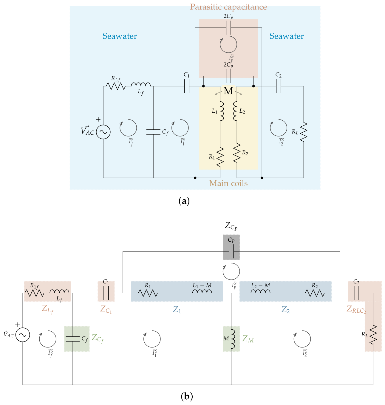
Wireless charging in underwater applications is modelled using a specific circuit that takes into account the effects of the high conductivity of seawater. Therefore, the basic circuit typically used in air-based solutions needs to be slightly modified. In this way, in addition to the study of the compensation system, the effect of the gap between the power coils and the parasitic capacitance (
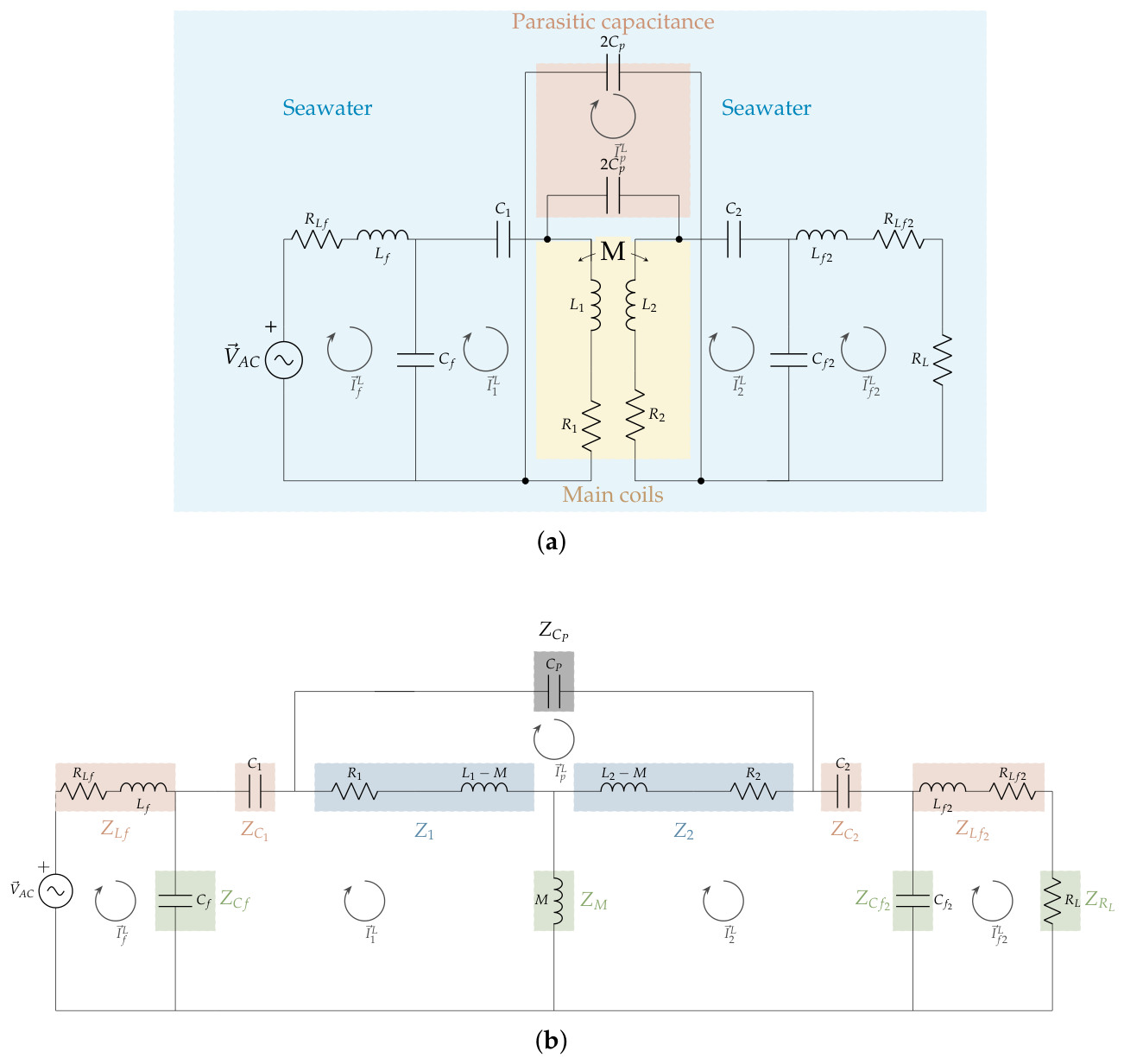
) introduced by the seawater environment should be considered. For this reason, two compensation topologies are under study in this work: LCC-S and LCC-LCC. The schematics of the circuits are shown in
Figure 1 and
Figure 2. The electrical variables of the circuits are denoted with the superscript S and L to refer to LCC-S and LCC-LCC, respectively. It should be noted that the parasitic capacitance is represented by two identical capacitors of value 2
in order to preserve the symmetry of the equivalent circuit while modelling the distributed nature of the parasitic coupling. Since both capacitors are connected in series, their equivalent capacitance is
corresponding to the total parasitic capacitance extracted from the electromagnetic simulations. This representation follows the modelling approach proposed in [
17].
In contrast to air-coupled coils, the schematics include parasitic capacitances to model seawater applications accurately.
The resonance conditions for the LCC-S network are defined by Equations (
1)–(
5):
The magnetic coupling between coils is represented by means of a T-type equivalent circuit. The corresponding branch impedances are defined in Equations (
6)–(
13).
The parasitic capacitance
, which physically arises between the surfaces of the two coils, is included as an additional branch of impedance
, defined in Equation (
13).
This additional branch introduces an independent current loop,
, connecting the primary and secondary sides directly. The complete system is described by the four mesh equations obtained from Kirchhoff’s voltage law, given in Equations (
14)–(
17).
The remaining currents are then obtained sequentially, as shown in Equations (
18)–(
20).
The source voltage required to deliver the specified output power is subsequently calculated using Equation (
21).
Finally, the transfer efficiency is calculated as the ratio between the power delivered to the load
and the total dissipated power, which also accounts for the winding resistances
and
, as expressed in Equation (
22).
In case of LCC-LCC compensation, the series compensation on the secondary side is replaced by an LCC network symmetrical to that of the primary, as shown in
Figure 2. The corresponding design parameters, obtained using the same design criterion as for the primary side (
), are given in Equations (
23) and (
24).
The magnetic coupling model and the representation of the parasitic capacitance
remain unchanged with respect to the LCC-S case, as shown in Equations (
25)–(
34).
Consequently, the differences between the two topologies are confined exclusively to the secondary compensation network. As a result of introducing the secondary LCC network, the secondary-coil current
no longer coincides with the load current, and an additional mesh appears at the output branch (
,
), whose current is denoted as
. The system is therefore described by five additional mesh equations, given in Equations (
35)–(
39).
The secondary-coil current
is obtained first, as given in Equation (
40).
The currents
and
are then obtained jointly by solving the corresponding mesh equations for the parasitic branch and the primary coil, respectively, as shown in Equations (
41) and (
42).
The procedure for obtaining
and the source voltage
, given in Equations (
43) and (
44), is identical to that used for the LCC-S topology, since the primary compensation network remains unchanged.
The transfer efficiency is expressed in Equation (
45), which is similar to Equation (
22), with the load current
replaced by
, and with
now denoting the secondary-coil current in the resistive loss term
.
As can be observed, efficiency depends on the system component values for both compensation systems. In this way, variations in resistances, as well as capacitor values, can modify the efficiency of the system. These variations can be related to the environment temperature.
The resistance of each winding (
,
and
) can be updated according to Equation (
46):
where
,
is the resistance at the reference temperature of 20 °C,
is the temperature coefficient of the conductor (0.00393 °C
−1), and
.
On the other hand, capacitances can be modified by following Equation (
47):
where
,
is the capacitance at the reference temperature of 20 °C,
is the temperature coefficient of the capacitor (
), and
.
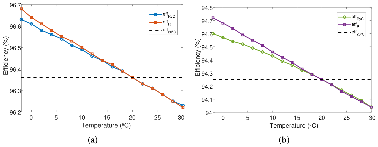
By incorporating these effects into efficiency evaluation, the model enables a more realistic prediction of the system performance over a wide range of operating conditions. To verify this, the resulting efficiency was evaluated over a representative seawater temperature range (
–
) for both compensation topologies, comparing three cases: the standard efficiency with all components fixed at their nominal
values (
), the efficiency obtained when only the winding resistances are updated with temperature (
), and the efficiency obtained when both the winding resistances and the compensation capacitors are updated with temperature (
).
Figure 3 compares, for each compensation topology, the three case studies described above. As shown in the figure, the three curves intersect exactly at
, the reference temperature at which all components take their nominal value: below this point both
and
exceed
, while above it both curves fall below the standard value.
As expected, the efficiency of both topologies decreases as the temperature rises, due to the corresponding increase in conductor resistance and the associated capacitance variation. Considering only the resistance variation, the LCC-S system experiences a reduction of over the considered temperature range (from at to at ), while the LCC-LCC system shows a slightly larger reduction of (from to ). When the temperature dependence of the compensation capacitors is also included, the resulting efficiency follows the same overall trend as , since the capacitance variation does not reverse the direction of the resistive effect, it only modulates its magnitude. For both topologies, the influence of the capacitance variation is more noticeable at low temperatures than at high temperatures: the difference between and is largest near and progressively narrows as the temperature approaches , where the three curves converge.
The efficiency gap between the two topologies also widens slightly with increasing temperature, from at to at , indicating that the additional resistive losses of the LCC-LCC output filter become marginally more significant as the conductor resistance increases with temperature.
These results indicate that colder seawater environments are slightly beneficial for the efficiency of the proposed wireless charger, consistent with the typical operating conditions of AUVs, which frequently perform missions in deep or high-latitude waters with low temperatures. Although the magnitude of this improvement is moderate (below over the considered range for LCC-S, and below for LCC-LCC), it confirms that the thermal behaviour of the conductors introduces no disadvantage in cold-water scenarios.
Given that the variation in efficiency introduced by ambient temperature is small compared to the effects of gap and coil size, temperature is not further considered in the remainder of this work, and all subsequent analyses assume components at their nominal values at .
3. Efficiency Comparison Between LCC-S and LCC-LCC
The selection of the coil geometry is based on a previous study [
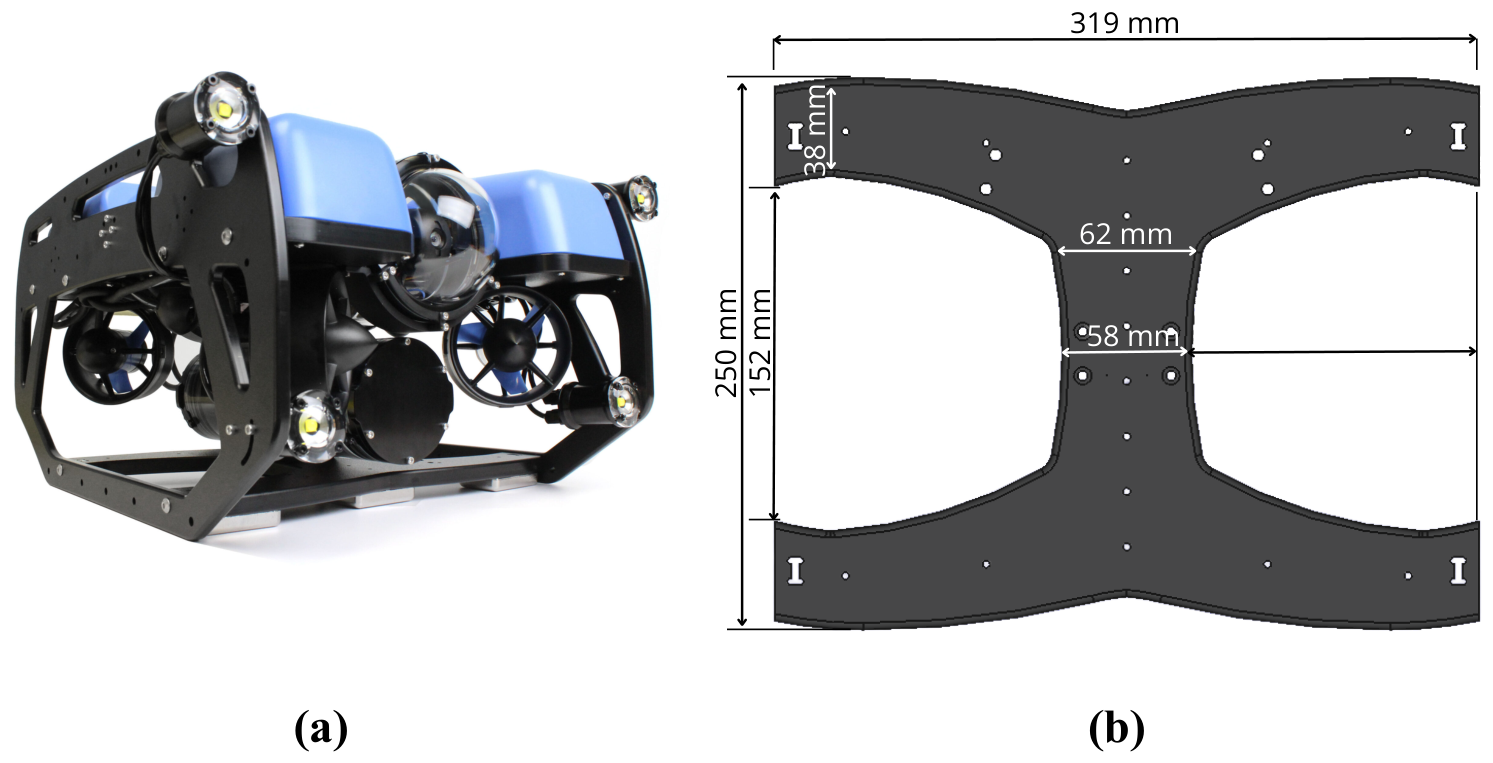
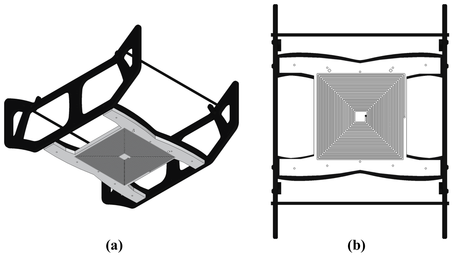
13], where several coil shapes were considered: circular, square, and DD configurations. It should be noted that the same topology and configuration are selected both for the primary and secondary sides. As analysed in the previous work, each option presents different features. Circular coils are typically more tolerant to rotational misalignment, square coils tend to achieve better power transfer efficiency, and DD coils can be more easily adapted to irregular surfaces. These topologies were evaluated considering their feasible integration within the base of a commercial underwater drone, whose surface is not continuous and includes openings that must remain accessible, as shown in
Figure 4.
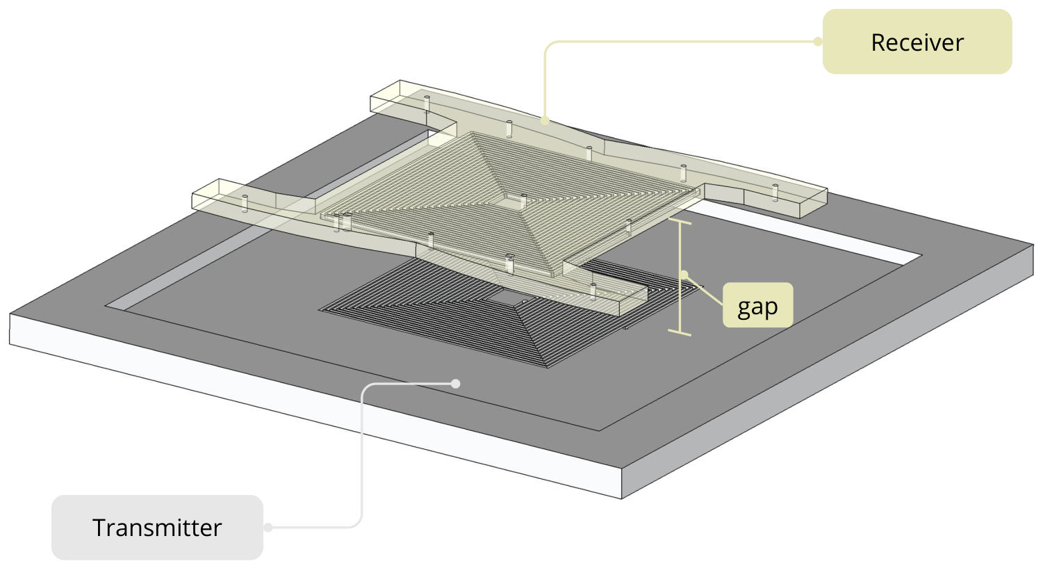
In our previous work, the selection of the most suitable topology was discussed. The results showed that increasing the number of turns leads to higher inductance and coupling, but also increases both resistance and parasitic capacitance. In parallel, an additional study examined the effect of the gap between coils, confirming that larger distances reduce both coupling and parasitic effects. Although the DD topology achieved the highest coupling values, it also exhibited the largest parasitic capacitance and higher resistive losses, while the circular geometry showed lower capacitance but more moderate coupling. When all factors were considered together, including their impact on system efficiency, the square geometry provided a more balanced outcome and it is therefore selected as the coil topology for the system described in this paper. The design of the Polylactic Acid (PLA) base for the power coil was made in FreeCAD, following the geometry of the drone, as illustrated in
Figure 5 and
Figure 6.
Although the previous study specified that the geometry used is square, the final design still needs the study of the final dimensions of the coil (optimised number of turns N) and the choice between LCC-S or LCC-LCC compensation networks. This is the first contribution of this paper. Although a higher number of turns and a more elaborate compensation network are generally used to improve the coupling and the robustness of the wireless link, both choices also introduce additional resistive losses, weight and a decremented reliability.
For this reason, the following subsections present a systematic comparison between and turns, and between the LCC-S and LCC-LCC topologies, in order to identify the configuration that offers the best trade-off between efficiency and robustness under realistic operating conditions. In addition, the influence of environment temperature on the resistive and capacitive components of the system is analysed, since seawater temperature can vary significantly depending on the depth and location of the AUV operation.
To assess the influence of the compensation network on the overall system performance, a comparative analysis was carried out between the LCC-S and LCC-LCC topologies. This was done based on the analytical characterisation of the U-WPT for these two compensation systems, as described in
Section 2. For this task, two square coil sizes,
and
turns, were considered. For each case, the electrical parameters of the coils (
,
,
,
,
and
) were obtained as a function of the gap between coils (25 mm to 50 mm) by using Ansys Maxwell 2021.
Table 1 summarises the resulting parameters. For each analysed coil geometry and separation distance, the transmitter and receiver coils were modelled using their actual dimensions and material properties. The eddy current solver was employed to determine the self-inductances (
and
), winding resistances (
and
), and magnetic coupling coefficient (
) at the operating frequency of 85 kHz. The parasitic capacitance values reported in this table were obtained from the electrostatic solver available in Ansys Maxwell. For each coil geometry and separation distance, the transmitter and receiver windings were defined as independent conductors immersed in the seawater domain, and the equivalent capacitance between both coils was extracted from the resulting capacitance matrix. This procedure was repeated for all analysed geometries and air gaps, providing the parasitic capacitance values used in the equivalent circuit model. In this way, for
, the parasitic capacitance decreases from 0.84 nF to 0.54 nF as the gap increases from 25 mm to 50 mm, while for
the corresponding range is 1.23 nF to 0.77 nF, proportionally higher due to the larger coil surface. In both cases, the coupling coefficient
decreases with the gap.
Based on these parameters, the AC-AC efficiency was calculated using the analytical model presented in
Section 2. PLECS circuit simulations were additionally performed for all evaluated gaps and turn numbers to cross-validate the analytical model, yielding a maximum deviation of 0.06 percentage points with respect to the analytical results for both topologies. Given this close agreement, only the analytical efficiency values are reported in
Table 2, which reports the resulting efficiency for both compensation topologies and both coil sizes.
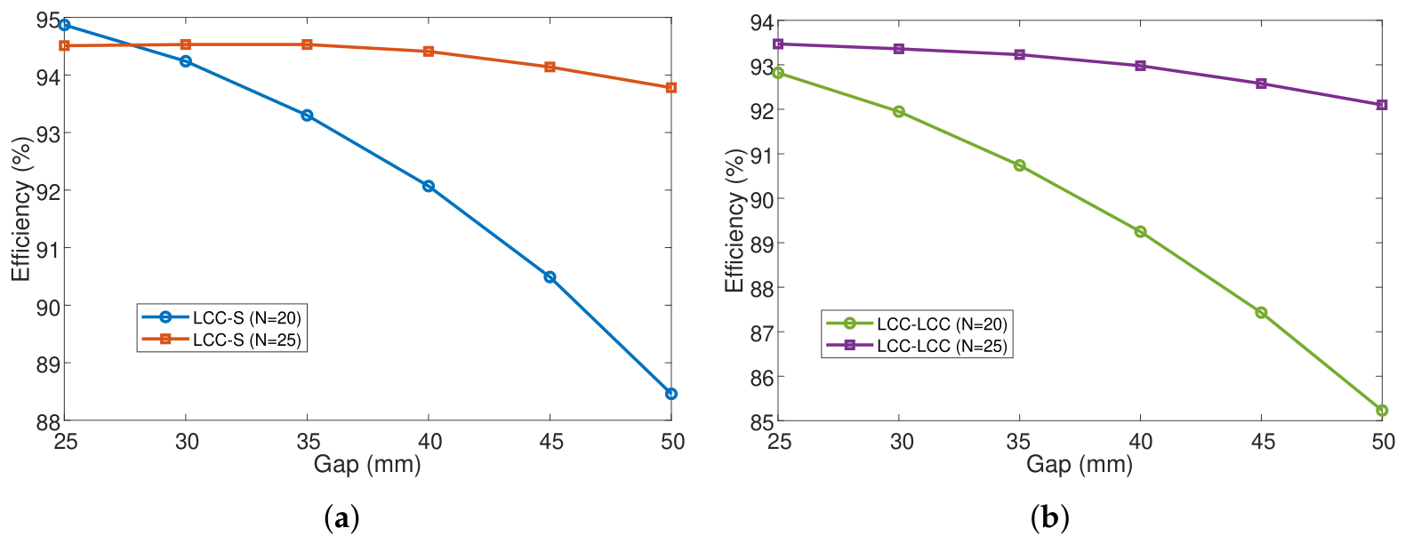
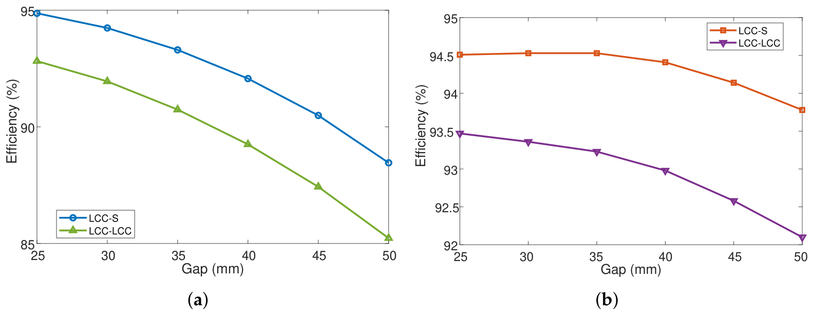
The efficiencies reported in
Table 2 were obtained under the nominal operating conditions considered for the proposed underwater wireless charger. To facilitate comparison, the
Figure 7 and
Figure 8 have been added. All simulations were carried out at a switching frequency of 85 kHz, with a DC input voltage of 100 V, and a load resistance of
Ω. Component values correspond to those calculated for each analysed topology according to the design methodology described in
Section 2.
The results show that, under all evaluated conditions, the LCC-S topology achieves a higher efficiency than LCC-LCC. This conclusion can be attributed to the additional resistive losses introduced by the output filter components (the inductor and its associated series resistance). These losses are not included in LCC-S, as the load is connected directly to the secondary side.
Additionally, it is observed that the difference on the efficiency between the two topologies is not constant, but depends on both the coil-to-coil distance and the coil size. That is, for , the difference between LCC-LCC with respect to LCC-S increases from 2.05 to 3.41% as the gap increases from 25 mm to 50 mm. For , the same trend is observed, but with a smaller difference (0.98 to 1.69% over the same gap range).
Taking into account the results presented throughout this subsection, the square coil is selected over the configuration, as it provides a higher AC-AC efficiency across the entire gap range, together with a lower sensitivity to the efficiency gap introduced by an additional compensation stage.
4. Experimental Validation
The design proposed in the previous sections was experimentally evaluated. To this end, two square coils with N = 25 turns were constructed using an LCC-S compensation system calculated in accordance with the final values of the coils. The values used in this system are presented in
Table 3. It should be noted that the inductance values measured in the manufactured prototype differ slightly from those predicted by the electromagnetic simulations. This difference is mainly attributed to the practical implementation of the coils, including manufacturing tolerances, the final winding arrangement, and the limitations inherent to the numerical model. Since the compensation network was designed for the actual prototype, the final capacitor values were calculated using the experimentally measured inductances reported in
Table 3 rather than the simulated ones.
The power coils were constructed using Litz wire, which is the recommended material for high-frequency applications. On the other side, for the compensation system, polyester film material was used for capacitors, and an air-core inductor, made of Litz wire, was used for series inductance () to prevent magnetic saturation of the ferrite core.
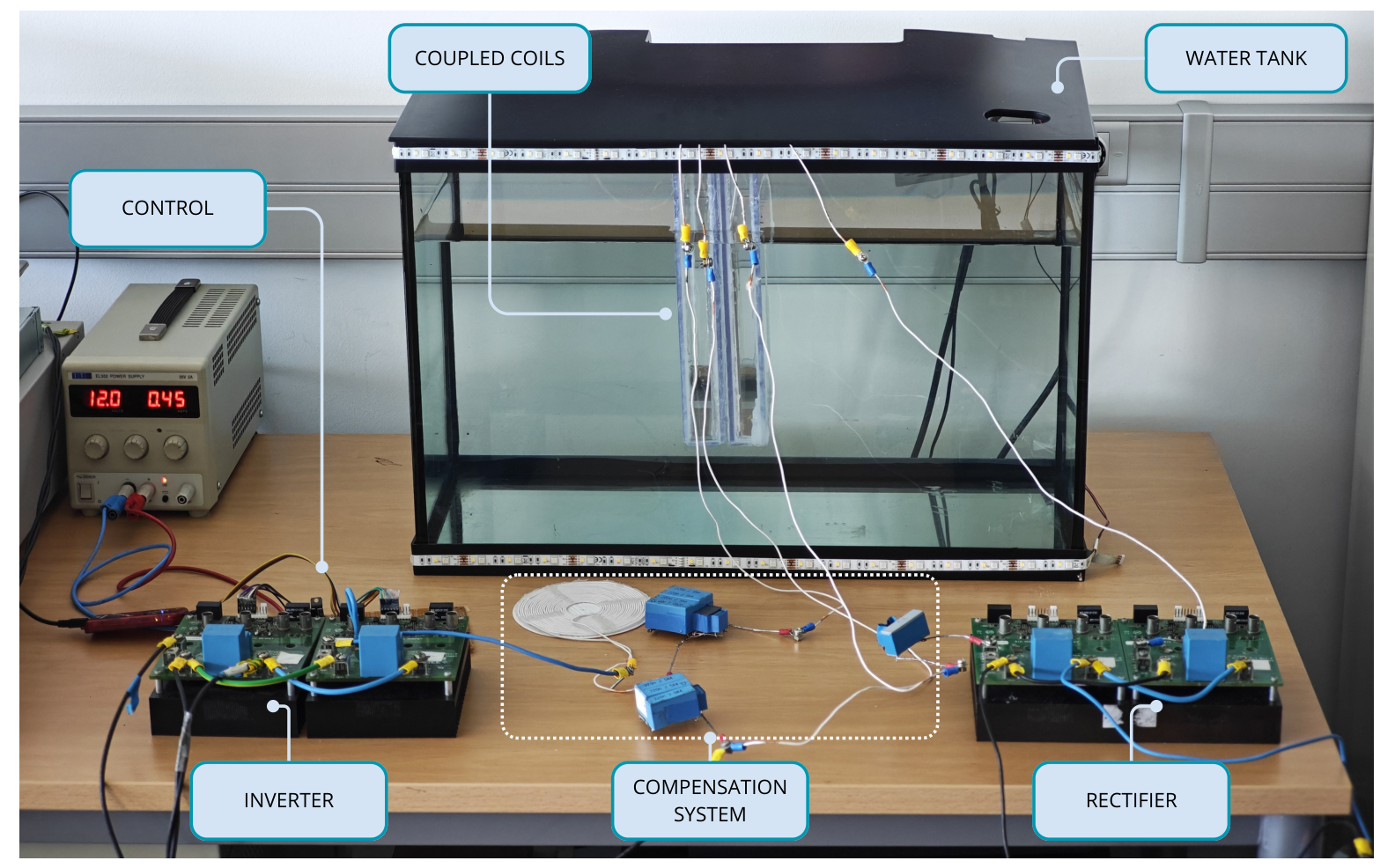
Regarding the power converters, the experimental setup relies on four CREE KIT8020-CRD-8FF1217P-J evaluation boards, each fitted with C3M0025065D CREE SiC MOSFETs, which act as the inverter on the primary side and the rectifier on the secondary side. The DC input voltage comes from an ITECH-BSS2000 power supply, while the inverter switching signals, set at 85 kHz, are generated by an algorithm running on a PICKIT4 device built around a DSPIC30f4011 digital signal processor (DSP). The AUV battery, in turn, is emulated through an EA-EL 9080-200 electronic load.
As a first approach to reproducing seawater conditions for the wireless charger, a 75-litre fish tank was used. From the fish tank’s total capacity, a total of 56.7 litres was required to carry out the experimental validation. The experimental setup can be observed in
Figure 9.
To reproduce representative marine environments, sodium chloride (NaCl) was progressively dissolved in the water contained in the experimental tank until reaching three different concentrations: 2%, 3% and 4%. The water temperature was 21 °C.
For each salinity level, the transmitter and receiver coils were positioned at a fixed distance of 25 mm, corresponding to the nominal operating condition selected in the previous section. The output load resistance was kept constant throughout all experiments in order to isolate the effect of salinity. The different operating points were obtained by progressively varying the DC input voltage supplied by the power source. Once the steady-state operating condition was reached, the input power ( × ) and output power ( × ) were measured and the DC-DC efficiency was calculated by following × 100%.
Additionally, to provide a comprehensive experimental validation of the proposed LCC-S compensation network, the system was evaluated under different operating conditions for each salinity level. Instead of measuring the efficiency at a single operating point, the transferred power was evaluated over the operating range required by the target AUV application while maintaining the same resonant frequency, load resistance, coil alignment, and separation distance. This procedure makes it possible to analyse the evolution of the power transfer efficiency over the complete operating range and to assess whether the influence of seawater salinity depends on the transferred power.
The selected power range was established according to the charging requirements of the target AUV platform. In particular, the wireless charger was designed for compatibility with the 14.8 V, 18 Ah lithium-ion battery employed by the commercial BlueROV2 platform. This battery corresponds to a nominal energy capacity of approximately 266 Wh and represents the expected operating condition of the proposed charging system. Consequently, the experimental operating points were selected to cover the power range required during the battery charging process, allowing the efficiency of the proposed LCC-S topology to be evaluated under representative operating conditions.
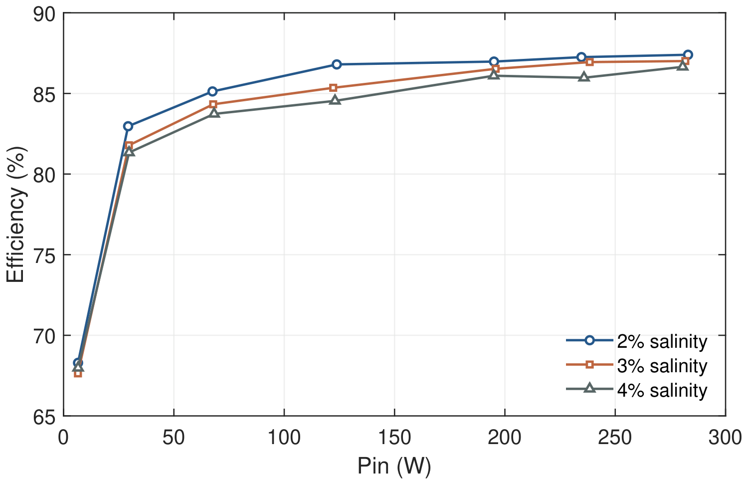
Figure 10 presents the measured efficiency as a function of the transferred power for the three analysed salinity levels (2%, 3% and 4% NaCl concentration). Each point corresponds to the average value obtained after reaching steady-state operation under the selected input power. A total of 2 measurements per point was considered in this study.
The results obtained with these experiments show that, in all cases, the efficiency exhibits the expected behaviour of resonant inductive power transfer systems, increasing rapidly at low power levels before progressively converging towards a nearly constant value as the transferred power increases.
This behaviour is mainly explained by the relative contribution of the fixed losses associated with the power converters, magnetic components and compensation network. At low transferred power, these losses represent a significant fraction of the total input power, resulting in a comparatively low overall efficiency. As the transferred power increases, the fixed losses remain practically unchanged while the useful transferred power grows, causing the efficiency to increase until the main loss mechanisms are those inherent to the resonant link itself. Consequently, the efficiency tends to stabilise close to its maximum operating value.
Considering the nominal charging power required by the selected battery, the proposed prototype reaches an experimental AC-AC efficiency of 94.3% and a DC-DC efficiency of approximately 87% at its intended operating point (around 260 W). The remaining difference is attributed to the power conversion stages. Both the inverter and the rectifier are implemented using CREE/Wolfspeed C3M0025065D SiC MOSFETs (650 V, = 25 mΩ typical), configured as full-bridge circuits on the primary and secondary sides, respectively. The conduction and switching losses of these eight devices at the 85 kHz operating frequency account for the additional losses observed between the AC-AC and DC-DC efficiency values.
These values demonstrate the feasibility of the proposed LCC-S wireless charging system for commercial underwater vehicles operating under different seawater salinity conditions. These results are consistent with previous studies on underwater wireless power transfer. In particular, the experimental study reported in [
7], also operating at 85 kHz, showed that increasing seawater salinity reduces the transfer efficiency due to the additional conductive losses introduced by the surrounding medium. Although the operating conditions differ, both studies consistently show that increasing seawater salinity degrades WPT efficiency. Compared with [
7], the proposed charger achieves an overall DC–DC efficiency of 87% while transferring 266 W across a 25 mm air gap.
Although the achieved efficiency is sufficient to validate the proposed design methodology and confirms the robustness of the selected compensation topology, it also has the possibility for future optimisation. Future work will therefore focus on reducing the remaining losses associated with the magnetic components, compensation network and power conversion stage, with the objective of increasing the overall system efficiency beyond 90%.
5. Conclusions
This paper has presented the design, simulation, and experimental validation of an inductive wireless power transfer system for a commercial underwater drone, focusing on the compensation system used, the influence of seawater salinity and temperature on the overall system performance.
Regarding the coil design, a square geometry was selected among circular, square, and DD configurations, as it provided the most balanced trade-off between coupling coefficient, resistive losses, and parasitic capacitance, while being compatible with the physical constraints of the commercial drone base.
On the other hand, the comparative analysis between the LCC-S and LCC-LCC compensation topologies showed that LCC-S consistently achieved a higher AC-AC efficiency across the entire evaluated gap range (25–50 mm), for both N = 20 and N = 25 turns. This behaviour has been associated with the additional resistive losses introduced by the output filter inductor of the LCC-LCC network. In this way, the N = 25 square coil was finally selected, as it provided higher efficiency and lower sensitivity to the gap between coils compared to the N = 20 configuration.
Additionally, the study of the influence of ambient temperature on the system parameters shows that colder seawater is slightly beneficial for efficiency, due to the reduction of copper resistivity at low temperatures. Although the magnitude of this effect was moderate (below 0.5% for LCC-S and below 0.7% for LCC-LCC over the evaluated range of −2 to 30 °C), it confirms that the thermal behaviour of the windings does not introduce any remarkable disadvantage under typical AUV operating conditions in deep or high-latitude waters.
The experimental validation, carried out in a controlled tank with 2%, 3%, and 4% NaCl concentrations, confirmed that the efficiency increases rapidly at low input power before stabilising close to a maximum value as the fixed losses become relatively less significant. At the nominal charging power required by the target 14.8 V, 18 Ah lithium-ion AUV battery, the proposed LCC-S prototype achieved an experimental efficiency of approximately 87%, which validates the feasibility of the proposed design methodology under representative marine salinity conditions.
The results confirm that the proposed square-coil LCC-S wireless charger provides a robust and efficient solution for the wireless charging of commercial underwater drones, while also highlighting that salinity variations within the typical oceanic range have a limited but non-negligible impact on system efficiency. Future work will focus on reducing the remaining losses associated with the magnetic components, compensation network, and power conversion stage, with the aim of increasing the overall system efficiency beyond 90%, as well as extending the experimental validation to a wider range of gap distances, misalignment conditions, and real seawater deployments beyond the controlled tank environment used in this study. Additionally, future work will include an experimental assessment of the influence of seawater temperature under controlled thermal conditions in order to validate the analytical model over the complete operating temperature range.