1. Introduction
The rapid advancement and widespread deployment of photovoltaic (PV) technology have positioned solar energy as a key pillar in the transition toward sustainable energy systems. As PV installations operate under dynamic environmental conditions, maximizing energy extraction remains a critical challenge. Maximum power point tracking (MPPT) techniques address this issue by continuously adjusting the operating point despite variations in solar irradiance and temperature [
1].
Numerous MPPT methods have been developed, each with specific advantages and limitations. Classical techniques such as Perturb and Observe (P&O) [
2], Incremental Conductance (IncCond) [
3], and voltage-based MPPT [
4] remain widely adopted because of their simplicity. However, P&O suffers from steady-state oscillations, IncCond entails higher computational complexity, and voltage-based approaches offer limited accuracy under non-standard conditions.
Partial shading is particularly challenging because non-uniform irradiance caused by clouds, buildings, vegetation, or nearby structures produces multiple local maxima in the power–voltage (P–V) characteristic [
4]. Conventional MPPT techniques may then become trapped in a local maximum instead of reaching the global maximum power point (GMPP), resulting in significant power losses [
5]. Advanced methods based on Particle Swarm Optimization (PSO) [
6], Genetic Algorithms (GAs) [
7], Fuzzy Logic Control (FLC) [
8], and Neural Networks (NNs) [
9] improve GMPP localization, but their computational requirements, parameter tuning, or training needs may limit real-time implementation in embedded PV converters [
10].
Among advanced control-oriented strategies, nonlinear techniques have attracted increasing attention because of their strong theoretical foundations and real-time suitability. Backstepping control [
11,
12] uses Lyapunov-based design to ensure fast convergence and robust tracking. Adaptive backstepping [
13,
14] extends this framework through online parameter estimation, improving robustness against model uncertainties and environmental variations. Sliding mode control (SMC) [
15,
16] provides strong robustness against disturbances and parameter variations by forcing the system trajectories toward a predefined sliding surface. In parallel, vision-based MPPT methods use image processing to estimate the irradiance distribution and identify shaded regions, thereby facilitating GMPP tracking under complex shading patterns [
17,
18].
These strategies offer different trade-offs in robustness, adaptability, convergence speed, and implementation complexity. However, their relative performance under dynamic irradiance and partial shading has not been sufficiently evaluated using a common experimental framework.
Wireless communication technologies are also increasingly integrated into PV systems for real-time data acquisition, remote diagnostics, supervision, and distributed control. Common alternatives include Wi-Fi, cellular networks, and IEEE 802.15.4-based wireless sensor networks [
19], which differ in data rate, latency, power consumption, reliability, scalability, and infrastructure dependency. Wi-Fi provides high data throughput and low local-area latency at the expense of higher power consumption [
20,
21,
22,
23]. Cellular networks such as 3G offer wide-area coverage for geographically dispersed installations [
24,
25], whereas IEEE 802.15.4 provides low-power mesh communication for distributed PV systems with moderate data-rate requirements [
12,
21,
26].
Despite the extensive literature on MPPT algorithms and wireless monitoring architectures, most studies address control design and communication infrastructure separately. Therefore, the combined influence of advanced MPPT strategies and communication-induced effects—such as latency, reliability, and scalability—on overall PV performance remains insufficiently explored, particularly in distributed systems operating under dynamic irradiance and partial shading.
This paper presents a unified experimental comparison of four advanced MPPT strategies—backstepping, adaptive backstepping, sliding mode control, and vision-based MPPT—combined with three wireless communication technologies: IEEE 802.15.4, Wi-Fi, and 3G. The configurations are evaluated using a common PV power stage, harmonized irradiance scenarios, and common performance indicators to provide practical, design-oriented criteria for selecting suitable MPPT–communication combinations.
The originality of this work is threefold: (i) it experimentally quantifies the joint influence of the control strategy and communication layer on MPPT performance; (ii) it demonstrates that the relative ranking of the MPPT methods is scenario-dependent, with adaptive backstepping providing the best behavior under uniform irradiance and vision-based MPPT under partial shading; and (iii) it establishes a direct link between communication characteristics and control-oriented metrics, including convergence time, tracking efficiency, GMPP success rate, lost energy, and latency behavior. Thus, the contribution is not the proposal of a new individual controller or communication architecture, but the unified and design-oriented evaluation of both layers in a distributed PV system.
2. Integrated PV System Architecture
This section describes the integrated PV system architecture used to evaluate the proposed MPPT strategies and wireless communication technologies. The architecture is based on a modular, grid-connected PV system previously developed and experimentally validated by the authors [
12,
14,
16]. In this study, the PV power stage and test scenarios were kept unchanged for all experiments, whereas communication-specific acquisition and control hardware was employed according to each evaluated architecture, and the MPPT algorithms and wireless communication technologies were systematically varied.
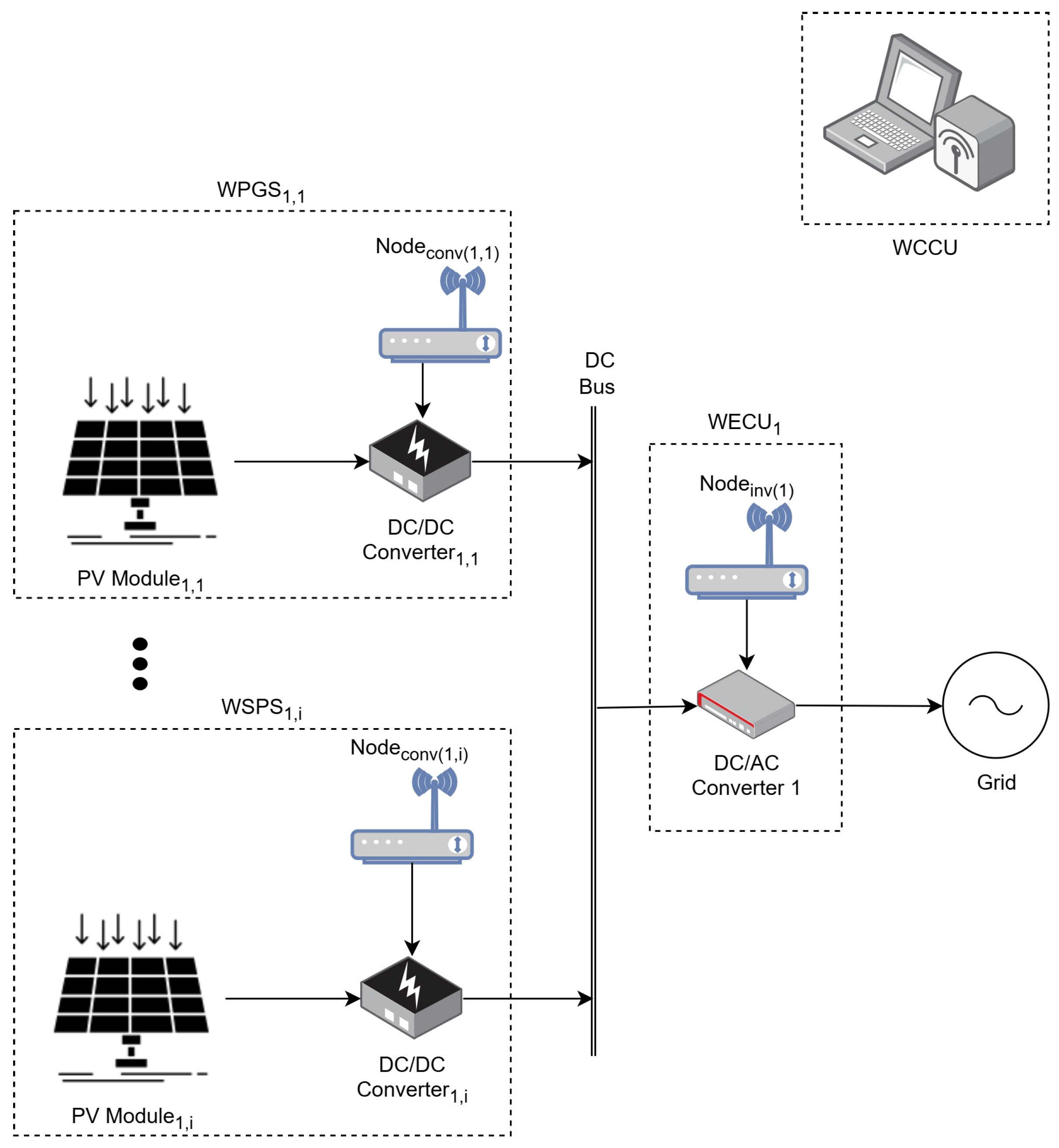
Figure 1 shows the three main subsystems: the Wireless PV Generation System (WPGS), the Wireless Energy Conversion Unit (WECU), and the Wireless Central Control Unit (WCCU).
2.1. Wireless PV Generation System (WPGS)
The WPGS comprises multiple Smart PV Units (SPVUs), each associated with a Wireless Conversion Node (WCN). Each SPVU includes a PV array connected to a DC/DC buck–boost converter and a wireless sensor node. The converter regulates the operating point of the PV array through MPPT control, while the sensor node acquires electrical measurements and transmits them to the central control unit. Based on the selected MPPT strategy, control commands are sent back to the WCN to regulate the converter duty cycle. The output power of all converters is aggregated on a common DC bus. Detailed electrical specifications of the PV modules, DC/DC converters, and associated power electronics are reported in [
12,
14,
16].
2.2. Wireless Energy Conversion Unit (WECU)
The WECU interfaces the common DC bus with the electrical grid and is responsible for DC/AC power conversion. It consists of a grid-connected inverter equipped with a wireless sensor node for remote monitoring and control. The inverter control system generates the required pulse-width modulation (PWM) signals and ensures grid synchronization through a zero-crossing detection mechanism.
A cascaded control structure based on proportional–integral (PI) controllers regulates the inverter current and DC-link voltage, ensuring stable operation and efficient power injection into the grid. The inverter hardware and control strategy remained unchanged throughout all experimental tests.
2.3. Wireless Central Control Unit (WCCU)
The WCCU acts as the coordination and decision-making node of the system. It manages communication with all WPGS and WECU nodes through an IEEE 802.15.4-based wireless sensor network [
27]. The received measurements are processed in real time, and control actions are generated accordingly. The WCCU implemented the different MPPT strategies under study—backstepping control, adaptive backstepping, sliding mode control, and artificial vision-based approaches—previously investigated in [
12,
14,
16,
18]. This centralized architecture enables the systematic evaluation of both control performance and communication-related effects, such as latency and reliability, and communication-specific acquisition and control hardware was employed.
In the evaluated architectures, the MPPT algorithms were executed on the corresponding embedded control platform, while the communication layer was used to transmit the measured PV/converter variables to the controller and return the corresponding duty cycle commands to the power stage. The effective control update periods were 20 ms for IEEE 802.15.4 and 15–20 ms for the Wi-Fi/3G implementations.
3. Overview of the MPPT Methods Under Comparison
This section presents the advanced MPPT strategies evaluated in this work and briefly describes their operating principles, implementation requirements, and expected performance characteristics. All MPPT methods were evaluated on the same distributed PV power stage and under the same irradiance scenarios; however, communication-specific embedded hardware was employed depending on the evaluated architecture. This section aims not to re-derive the control laws in detail but to highlight the key differences between the selected approaches—backstepping, adaptive backstepping, sliding mode control, and vision-based MPPT—in terms of robustness, model dependency, computational burden, and suitability for operation under partial shading conditions.
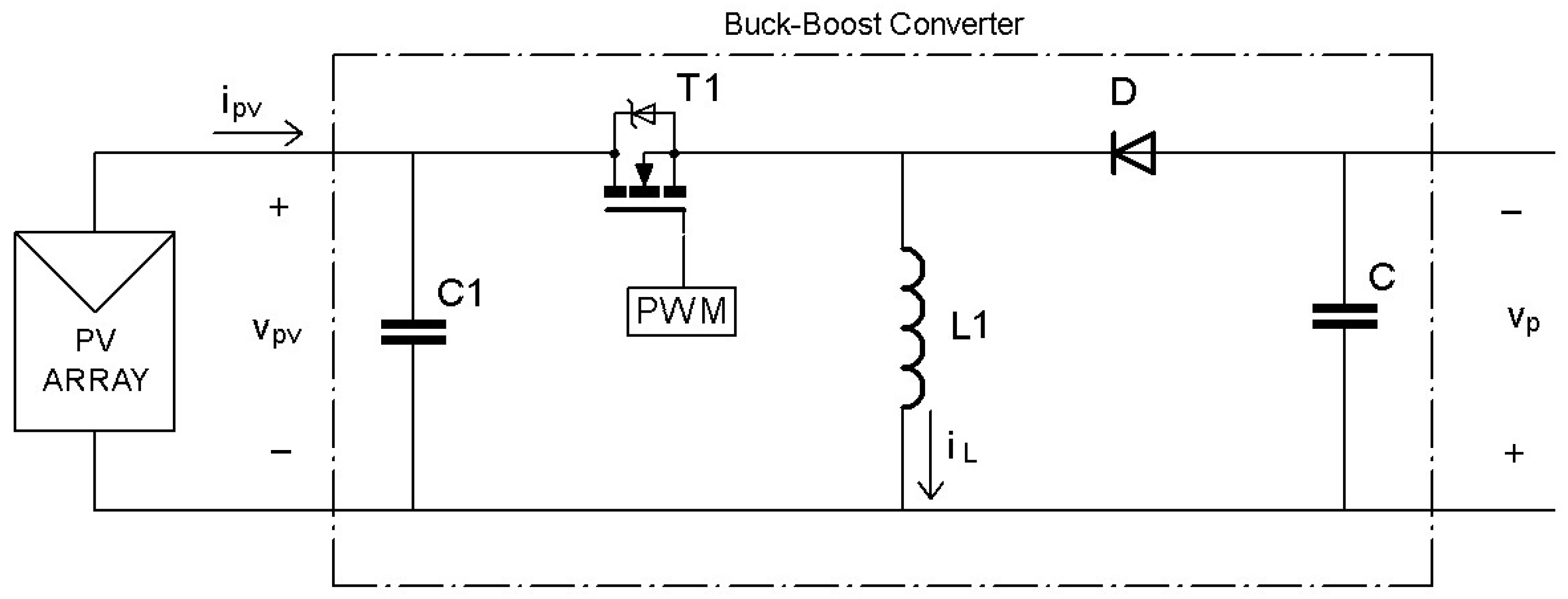
The control-oriented formulation is based on the buck–boost converter shown in
Figure 2, together with the main electrical variables considered in the mathematical model and control design.
The converter is rated for a maximum transferred power of 70 W, with an input voltage range of 10–70 V and a maximum output voltage of 100 V. It includes 1 mF input and output capacitors and a 780 µH inductor. The switching stage was implemented using a CSD19536KCS MOSFET driven by a FOD3180 driver and an MBR10200 diode.
3.1. Backstepping-Based MPPT
The backstepping-based MPPT strategy relies on nonlinear control theory to regulate the operating point of the PV system by directly controlling the duty cycle of the DC/DC converter through a Lyapunov-based design, ensuring closed-loop stability and convergence toward the maximum power point under time-varying irradiance. Considering the input capacitor
and inductor
, the simplified averaged model of the system can be expressed by Equations (1) and (2).
where
is the PV voltage,
is the PV current,
is the inductor current,
is the converter output voltage, and
is the converter duty cycle. The maximum power point condition is given by Equation (3).
where
is the power generated by the PV module. The control objective is to force the PV voltage to track the reference voltage associated with the maximum power point.
To guarantee global asymptotic stability, the time derivative of the Lyapunov function (with candidate function
) must be negative definite for any nonzero value of the voltage tracking error
. This requirement leads to the stabilizing condition
where
is a design parameter ensuring the convergence of the voltage error to zero. Based on this condition and the system dynamic model, a virtual control variable corresponding to the inductor current reference
is obtained.
Because the converter duty cycle directly influences the inductor current, a second feedback loop is introduced, with the tracking error (
). A composite Lyapunov function (
), including both the PV-voltage and inductor-current errors, is then defined, and the stability condition in Equation (5) is imposed.
with
and
, the stability of the closed-loop system is guaranteed. Following the backstepping procedure, the resulting control law provides the time derivative of the converter duty cycle as given by Equation (6). The actual duty-cycle value applied to the converter is obtained by integrating this virtual control signal. A complete derivation and experimental validation are reported in [
12].
This nonlinear formulation enables fast MPP tracking from real-time PV-voltage and current measurements. However, its performance may be affected by model and parameter uncertainties, particularly under partial shading, where multiple local maxima can occur.
3.2. Adaptive Backstepping MPPT
Adaptive backstepping MPPT extends the conventional backstepping framework by incorporating online parameter estimation mechanisms. This allows the controller to compensate for uncertainties in system parameters, such as variations in PV characteristics or converter dynamics, without requiring precise prior knowledge of the model [
14]. The control objective remains the regulation of the converter duty cycle to force the PV output voltage to track its MPP reference voltage, but the capacitance and inductance are now treated as uncertain quantities. They are redefined in Equation (7), and an additional parameter is introduced in Equation (8) to simplify the controller derivation.
The first voltage-control step follows the same Lyapunov-based procedure as conventional backstepping and yields the virtual inductor-current reference. The inductor-current error is subsequently introduced, and a composite Lyapunov function is defined for the voltage and current dynamics. Imposing the stability condition in Equation (9).
with positive design gains, guarantees closed-loop stability. The resulting expression for the Lyapunov derivative, incorporating the parameter estimates, is given by Equation (10).
From this expression, the controller defining the duty-cycle dynamics can be obtained, where
,
, and
,
, and
represent the estimated parameters. The estimation errors are defined as
Additional Lyapunov functions associated with these errors lead to the adaptation laws, Equations (12) and (13).
where
and
are positive adaptation gains. Incorporating these laws makes the global Lyapunov derivative negative definite, ensuring asymptotic convergence while the parameter estimates are updated online.
The adaptive formulation therefore improves robustness when converter parameters are not accurately known or vary during operation. This preserves accurate MPP tracking, avoids excessively conservative controller tuning, and maintains the dynamic response under changing environmental and operating conditions. This capability is particularly advantageous in PV systems operating under variable environmental conditions and non-stationary regimes.
3.3. Sliding Mode Control (SMC) MPPT
Sliding mode control is a nonlinear strategy that forces the system dynamics to evolve on a predefined sliding surface, providing robustness against structured uncertainties and external disturbances. This property is particularly useful in PV systems subject to irradiance changes, temperature variations, component aging, and communication-induced disturbances.
In the developments considered in this work, SMC is applied to the buck–boost converter. Since the buck–boost converter is a non-minimum phase system, the PV voltage must be controlled through the inductor current. Using the state-space averaged model under continuous conduction mode (CCM), the converter dynamics are expressed as
where the state vector is defined as
with
,
,
, and
. Here,
is the reference voltage associated with the maximum power point. A sliding surface with suitable dynamics for this application is defined as
where
and
are positive design parameters. The sliding mode exists when the conditions
and
are satisfied. This surface enables the regulation of the buck–boost converter input voltage while preserving the desired dynamic performance.
The control law comprises two terms, a corrective term and an equivalent control term:
where the corrective control is defined as
with
, and the equivalent control is obtained by imposing
,
which, for the buck–boost converter, yields
Thus, the final SMC law becomes
Closed-loop convergence is assessed using the Lyapunov candidate function
Its time derivative must satisfy
which ensures that the switching function is attractive. Based on this condition, the stability requirement leads to the constraint
thereby closing the SMC controller design.
The SMC-based MPPT controls the duty cycle of the DC/DC converter using measurements of PV voltage and current, and its inherent robustness makes it particularly suitable for rapidly changing irradiance conditions, partial shading scenarios, and distributed PV systems affected by communication delays and external perturbations. Once the system trajectories reach the sliding surface, the dynamics become insensitive to moderate parameter variations, which reduces dependence on accurate model tuning and facilitates practical implementation in real systems. Its discontinuous switching law may nevertheless produce chattering, increasing switching losses and device stress. This effect can be mitigated through suitable sliding-surface design and controller-gain selection. A detailed implementation and experimental validation are presented in [
16].
3.4. Vision-Based GMPP Localization and MPPT
Vision-based MPPT represents a fundamentally different approach compared with conventional electrical methods, as it incorporates external physical information obtained directly from the PV generator. Instead of inferring partial shading conditions solely from aggregated electrical measurements, this method exploits computer vision techniques to capture and process visual information from the PV array. This enables a spatial characterization of the shading pattern affecting the modules, allowing the control system to identify the region where the global maximum power point (GMPP) is likely to be located.
The proposed scheme integrates artificial vision as an advanced sensing layer within the PV control system. A digital camera positioned above the PV generator captures images covering the entire module surface. These images provide a spatial representation of the shadow distribution, making it possible to determine not only the presence of partial shading but also its intensity, extent, and relative position across the modules.
The acquired images undergo region-of-interest selection, RGB-to-HSV conversion, thresholding, morphological opening, and blob detection. HSV thresholding isolates the shaded regions, morphological filtering removes noise and isolated pixels, and blob detection identifies significant connected shaded areas.
For each PV module
j, a shadow-intensity parameter
is calculated from the average gray-level value of the pixels belonging to the shaded blob and can be expressed as
where
is the number of pixels within the shaded region, and
represents the gray-level value of each pixel. The shadow intensity is normalized within the range 0–100, where 0 corresponds to fully illuminated modules and 100 to maximum shading. The effective irradiance incident on each module under shading conditions is estimated. The shadow irradiance
is obtained from the estimated irradiance
through the experimentally derived relationship
where
represents the estimated irradiance of the PV generator. When no shading is detected, the estimated irradiance is used directly; otherwise, the last irradiance value measured under unshaded conditions is stored in
and used as a reference value.
The estimated irradiance distribution, together with the electrical measurements, defines a physically consistent voltage interval in which the GMPP is expected. Unlike global-search or metaheuristic methods, this approach restricts the search region using the observed shading distribution, thereby reducing the probability of convergence to local maxima. Once the candidate region is identified, the vision block provides the theoretical MPP voltage, vs, which is adjusted to obtain the final reference, vref, applied to the nonlinear DC/DC converter controller.
This functional separation between GMPP localization based on visual perception and dynamic MPPT based on nonlinear control constitutes a key methodological feature of the proposed approach. By combining environmental perception with advanced control techniques, the system is able to react rapidly to changes in shading patterns while maintaining stable operation and high tracking efficiency.
From an implementation perspective, the algorithm is developed using open-source computer vision libraries and low-cost webcam devices commonly available in PV installations. Although the method introduces additional computational requirements and depends on communication bandwidth when visual data are transmitted remotely, it provides a physically informed and highly effective strategy for GMPP identification. Detailed implementation and experimental validation are reported in [
18].
Nevertheless, practical deployment entails additional sensing, processing, and maintenance requirements. Image quality may deteriorate because of dust, rain, fog, or lens contamination, while real-time embedded processing and raw-image transmission may impose computational and bandwidth constraints. These limitations can be mitigated through local edge processing, protective camera housing, periodic image-based correction, or hybrid operation in which the visual layer is activated only when partial shading is detected.
Table 1 summarizes the control principle, model dependency, robustness, partial-shading capability, convergence speed, computational complexity, and required measurements of the four evaluated strategies. Overall, it highlights the complementary nature of the evaluated strategies: backstepping-based methods prioritize fast and stable electrical regulation, sliding mode control emphasizes robustness against uncertainties, and the vision-based approach provides the strongest GMPP localization capability under partial shading, although at the expense of higher sensing, computational, and communication requirements. These expected trade-offs are experimentally assessed in
Section 5.
4. Overview of the Wireless Communication Technologies Under Comparison
The wireless communication infrastructure analyzed in this work builds upon previous distributed PV monitoring and control architectures developed and experimentally validated by the authors [
12,
23,
25]. In earlier studies, Wi-Fi and 3G communication modules were integrated into PV generation nodes to enable real-time data acquisition and remote supervision, while IEEE 802.15.4-based wireless sensor networks were implemented to support low-power distributed coordination among multiple PV units [
12].
In this study, these communication technologies were not only employed for monitoring purposes but also systematically evaluated in terms of their interaction with advanced MPPT strategies. Their latency, reliability, scalability, and bandwidth characteristics were analyzed under dynamic irradiance and partial shading conditions, treating the communication layer as an active component influencing system behavior rather than as a passive data transport mechanism.
4.1. Wi-Fi Communication
Wi-Fi communication was previously integrated by the authors into distributed PV nodes to support high-frequency data transmission and supervisory control [
23]. Its high data rate and low local-area latency support frequent measurement updates, rapid control-signal exchange, and the larger data volumes required by vision-based approaches.
However, Wi-Fi networks typically exhibit higher power consumption compared to low-power wireless sensor networks and may experience congestion or interference in dense communication environments. While well suited for laboratory-scale and local distributed PV systems, scalability may become limited as the number of nodes increases.
In the implemented platform, Wi-Fi communication is based on UDP/IP transmission through a local wireless access point, with an effective sampling period of 15–20 ms. Its contention-based medium access may introduce moderate latency variability depending on channel occupancy and traffic conditions.
4.2. 3G Cellular Communication
3G cellular communication was previously employed by the authors for remote monitoring of geographically dispersed PV installations, enabling wide-area connectivity without the need for local networking infrastructure [
25]. Its main advantage lies in its extensive coverage; however, network routing and operator-dependent traffic conditions generally introduce higher and more variable latency than Wi-Fi and IEEE 802.15.4.
In the implemented 3G configuration, data are also transmitted through UDP/IP, with an effective sampling period of 15–20 ms, but the end-to-end communication path included the mobile network and operator-dependent routing. As a result, although the available data rate remains sufficient for supervisory monitoring and measurement transmission, the delay and jitter are significantly higher than in the local wireless architectures, which may penalize time-sensitive MPPT control tasks.
4.3. IEEE 802.15.4-Based Wireless Sensor Networks
Wireless sensor networks based on the IEEE 802.15.4 standard have been implemented by the authors as a low-power solution for distributed PV generation systems [
12]. These networks support mesh-based communication and enable scalable coordination among multiple Smart PV Units while maintaining reduced energy consumption at the node level.
On the implemented platform, measurements were sampled every 20 ms and transmitted in beacon-enabled mode using guaranteed time slots (GTSs), providing bounded and predictable delay behavior. This synchronized access reduces communication uncertainty and improves timing determinism for closed-loop MPPT operation. IEEE 802.15.4 also provides sufficient bandwidth for the electrical measurements required by the control algorithms and is suitable for autonomous embedded PV nodes; however, its lower data rate may constrain high-volume applications such as raw-image transmission in vision-based architectures.
Table 2 summarizes the implemented communication layers, sampling periods, latency behavior, data rate level, coverage, power consumption, and suitability for the evaluated MPPT architectures. Overall,
Table 2 shows that Wi-Fi prioritizes bandwidth, 3G provides wide-area coverage, and IEEE 802.15.4 offers low-power and more deterministic communication. Their influence on control performance is quantified in
Section 5 through latency measurements and tracking-efficiency analysis.
5. Experimental Methodology and Performance Evaluation Framework
This section presents the experimental methodology adopted to systematically evaluate the interaction between the selected MPPT strategies and wireless communication technologies. All experiments were conducted using the integrated PV architecture introduced in
Section 2. The PV power stage, converter parameters, irradiance scenarios, and evaluation criteria were kept common, whereas the communication-specific sensing, acquisition, and control hardware associated with each implementation is described in
Section 5.1.
The evaluation is structured around controlled irradiance variations, partial shading scenarios, and communication performance measurements. Both control-oriented and communication-related metrics are considered. Control performance was assessed through tracking efficiency, convergence time, steady-state behavior, GMPP tracking success rate, and lost energy. In parallel, communication characteristics, including latency and delay variability, were quantified in relation to their influence on control performance and energy extraction.
5.1. Experimental Platform
The experimental validation was carried out on a laboratory-scale modular distributed PV platform previously developed and experimentally validated by the authors [
12,
14,
16,
18]. The system integrates a buck–boost DC/DC converter, a DC/AC inverter stage for grid connection, distributed sensing nodes, and a centralized control unit interconnected through wireless communication technologies.
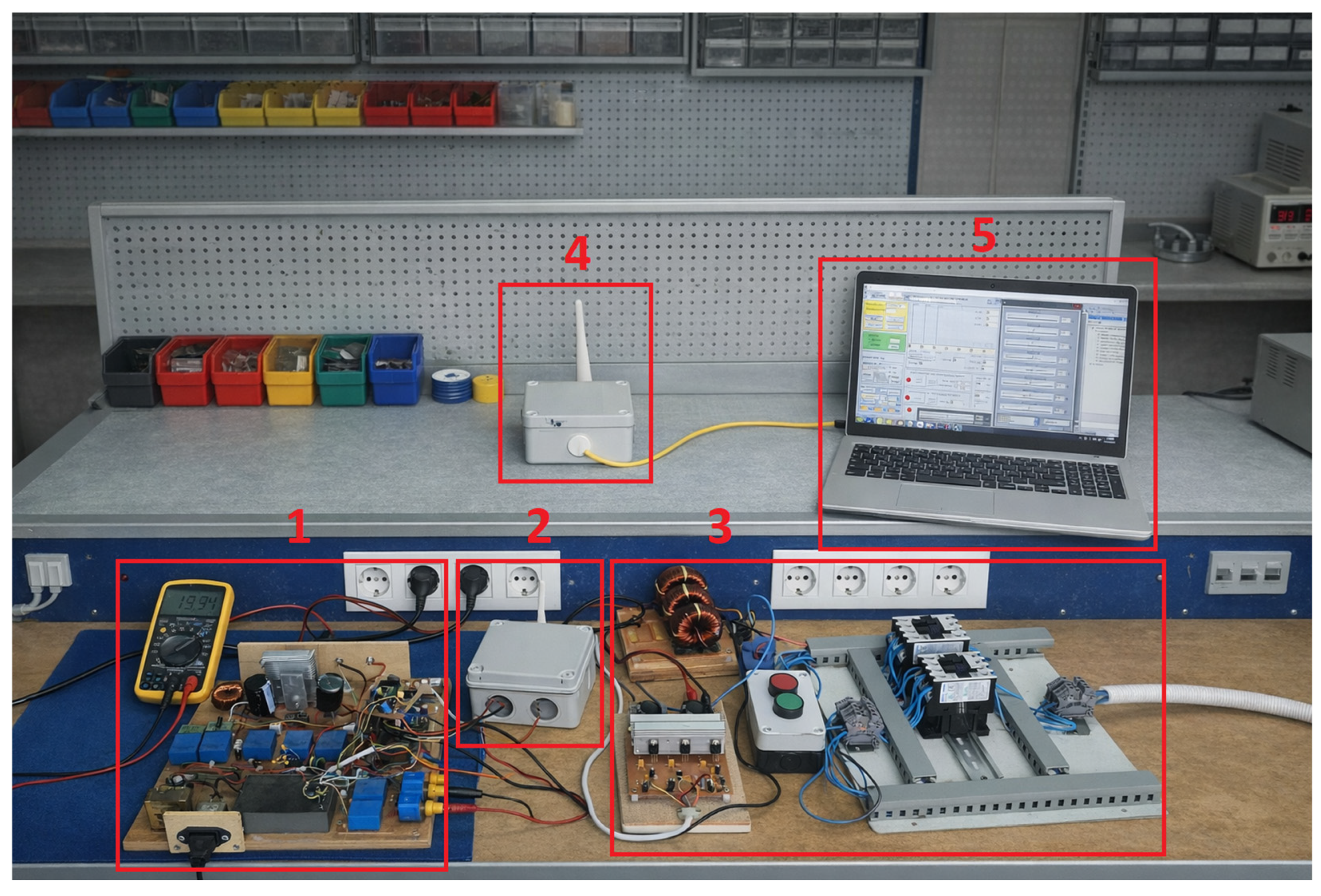
The complete experimental setup is shown in
Figure 3. The numbered elements correspond to: (1) the DC/DC buck–boost converter, (2) the sensor node associated with the Smart PV Unit, (3) the grid-connected inverter stage, (4) the PAN coordinator, and (5) the SCADA interface. The PV generator consists of three commercial PV modules (TVF Solar, Alicante, Spain) connected in series, each rated at 20.1 W under standard test conditions (1000 W/m
2, 25 °C), with a maximum power voltage of 17.5 V and a maximum power current of 1.15 A [
18]. The modules feed a 70 W buck–boost DC/DC converter (It is a design created by the authors) with an input-voltage range of 10–70 V, a maximum output voltage of 100 V, and an efficiency above 92%. The converter is driven by a 10-bit PWM signal with switching frequencies between 10 kHz and 30 kHz. The inverter stage interfaces the common DC bus with the grid and is responsible for the controlled injection of the power extracted from the PV generator. This DC/AC converter is associated with the corresponding filtering and protection elements. Its hardware and control structure were retained throughout the experiments so that the PV power-conversion stage remained common to all tests.
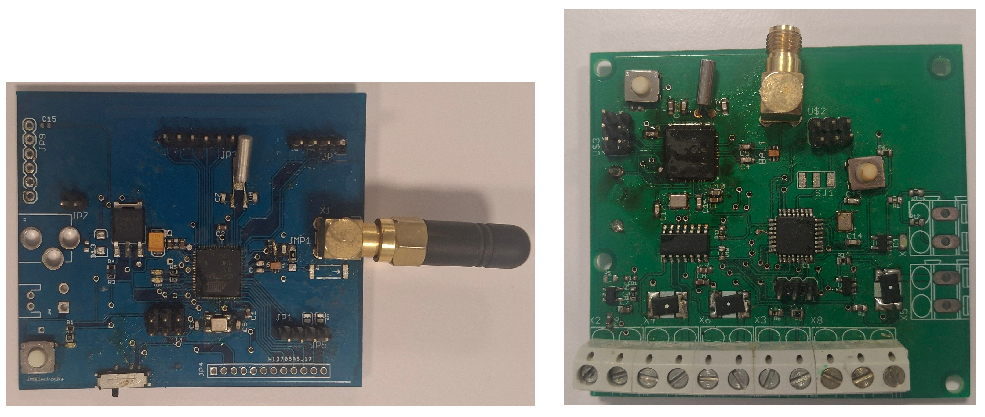
Two control and acquisition hardware configurations were employed depending on the communication architecture. For the IEEE 802.15.4-based wireless sensor network, each Smart PV Unit incorporates a dedicated sensor node composed of an ATmega328P (Microchip, Chandler, AZ, USA) for signal acquisition and local processing and an ATmega128RFA1 (Microchip, Chandler, AZ, USA) for communication management [
18]. PV voltage and current measurements are acquired through an external 16-bit MCP3428 ADC (Microchip, Chandler, AZ, USA). The electrical variables are sampled every 20 ms and transmitted in beacon-enabled mode using guaranteed time slots. Network synchronization and data aggregation are handled by a PAN coordinator, also based on the ATmega128RFA1, which forwards the measurements to the controller and returns the duty-cycle commands required for converter regulation [
18].
Figure 4 shows the PAN coordinator and the sensor node.
For the Wi-Fi and 3G scenarios, a dsPIC30F4011-based (Microchip, Chandler, AZ, USA) datalogger equipped with external 18-bit ADS8698 ADCs (Texas Instrument, Dallas, TX, USA) was employed. Data were transmitted to the remote control unit through UDP/IP, either via a local wireless access point for Wi-Fi or through a TP-Link cellular router for 3G. The sampling period was set to 15–20 ms, and the central processing unit executed the MPPT algorithms and returned the duty-cycle commands through the IP-based communication link.
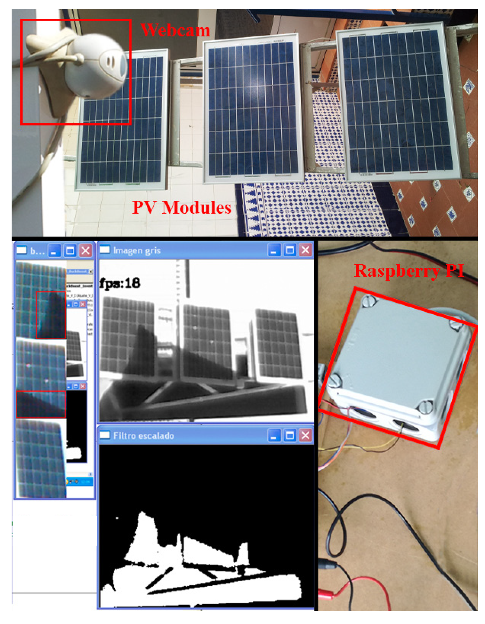
In the vision-based MPPT implementation, a low-cost 8 MP webcam connected to a Raspberry Pi running OpenCV (version 4.8.1) was used to detect partial shading in real time [
18]. The locally processed images were employed to estimate the irradiance distribution and compute the reference voltage associated with the GMPP.
Figure 5 shows the three-module PV generator and webcam in the upper part and the Raspberry Pi image-processing stage in the lower part. The vision subsystem provides an additional physical sensing layer, while the Raspberry Pi performs the local processing before the resulting information is integrated into the MPPT control loop.
The monitored electrical variables include PV voltage, PV current, and converter input/output variables; the vision-based configuration additionally provides the irradiance distribution inferred from image processing.
Table 3 summarizes the sensing and acquisition chains, including the measured variables, acquisition elements, resolution, sampling frequency, and synchronization role within the control loop.
As shown in
Table 3, the sensing chains are not fully identical across all architectures. The IEEE 802.15.4 configuration uses an MCP3428-based acquisition node, the Wi-Fi and 3G configurations use a dsPIC30F4011-based datalogger with ADS8698 converters, and the vision-based configuration incorporates an additional image acquisition and processing layer. These differences are explicitly considered as part of each complete implementation architecture.
A supervisory control and data acquisition (SCADA) interface was implemented for real-time visualization and structured data logging. Depending on the communication architecture, it received data through an IEEE 802.15.4 gateway or through the Wi-Fi/3G UDP/IP links. The interface also allowed the operating mode and MPPT strategy to be selected during each test. However, the control law was executed by the embedded control platform associated with each communication architecture; therefore, the SCADA subsystem acted only as a supervisory and experimental-support layer and did not directly execute the MPPT algorithm.
The PV power stage, inverter, converter parameters, filtering, and protection elements were retained throughout the experiments. However, the embedded processing platforms, acquisition chains, communication protocols, and sampling periods differed among the evaluated architectures. Consequently, the study should be interpreted as a comparison of complete MPPT–communication implementation architectures rather than as an isolated comparison of the communication media. Although part of the observed differences may reflect the combined influence of protocol, embedded processing, acquisition chain, and sampling rate, the common PV power stage, harmonized irradiance profiles, and common evaluation criteria provide a consistent system-level comparison.
Table 4 summarizes the main structural differences.
5.2. Test Scenarios and Experimental Protocol
The experimental campaign was organized into two complementary test groups: (i) uniform-irradiance dynamics to assess transient tracking behavior, and (ii) partial shading conditions to evaluate GMPP capability. For each operating condition, the communication layer was configured using Wi-Fi, 3G, or IEEE 802.15.4, and the resulting control performance and communication metrics were recorded simultaneously.
In the uniform-irradiance tests, step-like irradiance changes were intentionally applied to stress the controllers beyond typical field dynamics, following the rationale used in the remote-control platform validation [
25]. In the partial shading tests, repeatable shading patterns were imposed on the three-series PV string to generate multi-peak P–V characteristics, consistent with the methodology used in the vision-based MPPT validation [
18]. Across all scenarios, measurements of PV voltage and current, converter variables, and the communication latency associated with the control loop (sensor-to-controller and controller-to-actuator) were logged for subsequent analysis.
The comparative analysis used the following indicators. Convergence time is the time required by the MPPT-controlled system to reach and remain within a prescribed neighborhood of the new operating point after an irradiance or shading change. Tracking efficiency is the ratio between the energy extracted by the PV system and the theoretical maximum extractable energy over the same interval. GMPP tracking success rate is the percentage of partial-shading tests in which the controller converges to the global maximum. Lost energy is the relative difference between the theoretical GMPP energy and the energy extracted during the test interval. Latency refers to the end-to-end delay of the control-loop communication path, while reliability is discussed in terms of communication stability and timing consistency during the experimental campaign.
The communication architecture is not treated as a purely observational layer in this study. Since the evaluated MPPT strategies operate in closed loop, communication timing directly affects the measurement delivery, control update rate, and duty cycle command transmission and therefore has a measurable impact on real-time MPPT performance.
5.2.1. Uniform-Irradiance Dynamics (Stress Test)
Abrupt irradiance transitions were applied to evaluate convergence time, steady-state oscillations, and robustness under fast operating-point changes. Following [
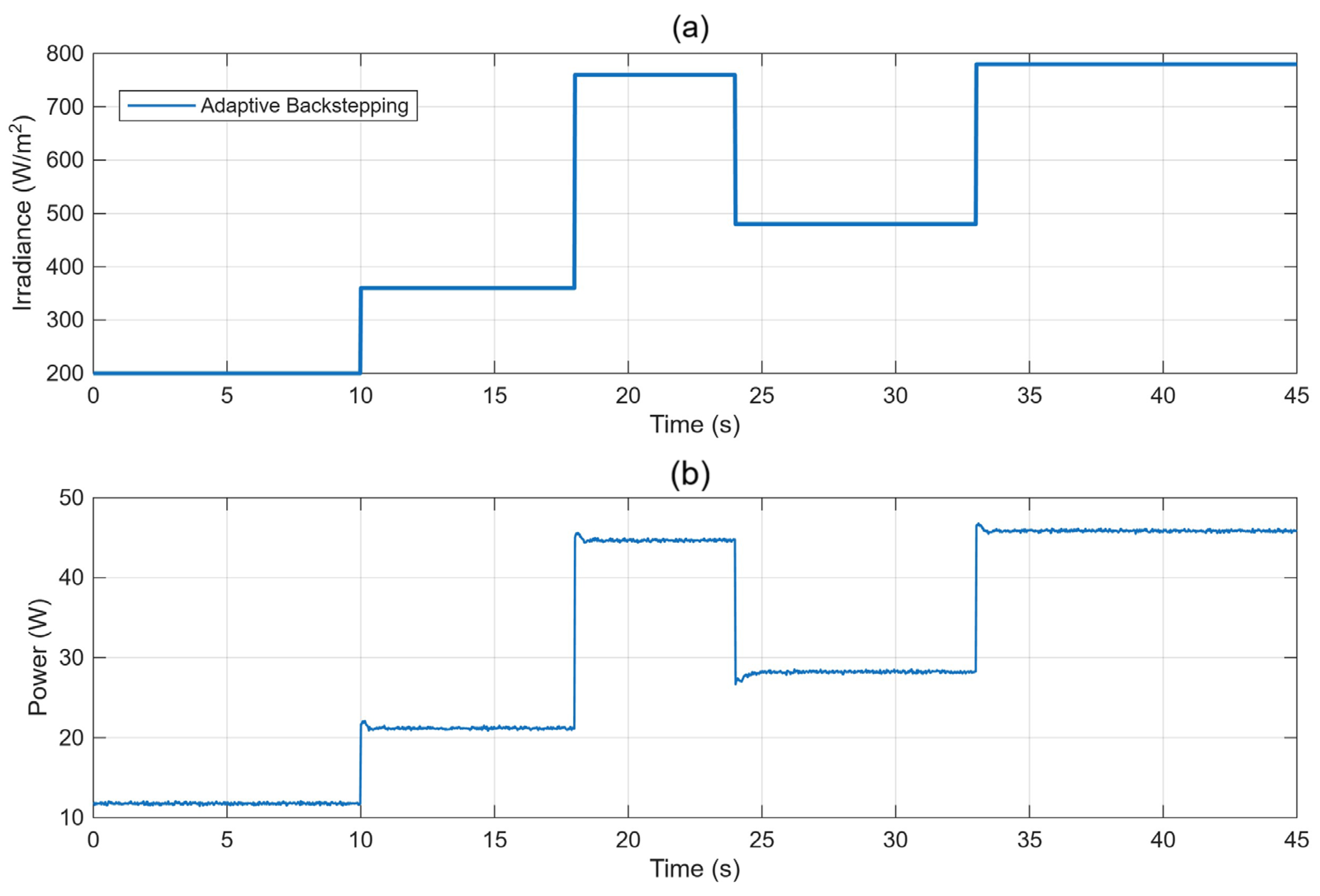
25], the irradiance profile consisted of successive plateaus of 200, 360, 760, 480, and 780 W/m
2, each maintained for a fixed time interval. This profile allows a direct assessment of how quickly each MPPT method updates its control action and how effectively the DC/DC converter tracks the commanded operating point under communication constraints. Representative time-domain responses are shown for selected MPPT–communication combinations, while aggregated indicators provide the complete comparison.
Figure 6 shows the adaptive backstepping response under the uniform-irradiance profile using IEEE 802.15.4.
Figure 6a depicts the imposed irradiance profile, while
Figure 6b presents the corresponding extracted PV power. The controller responds rapidly to each transition, with limited overshoot and low residual steady-state oscillation. The measured power levels are consistent with the expected variation in available PV power, confirming the correct operation of the converter and MPPT controller during the stress test.
To obtain further insight into the dynamic behavior,
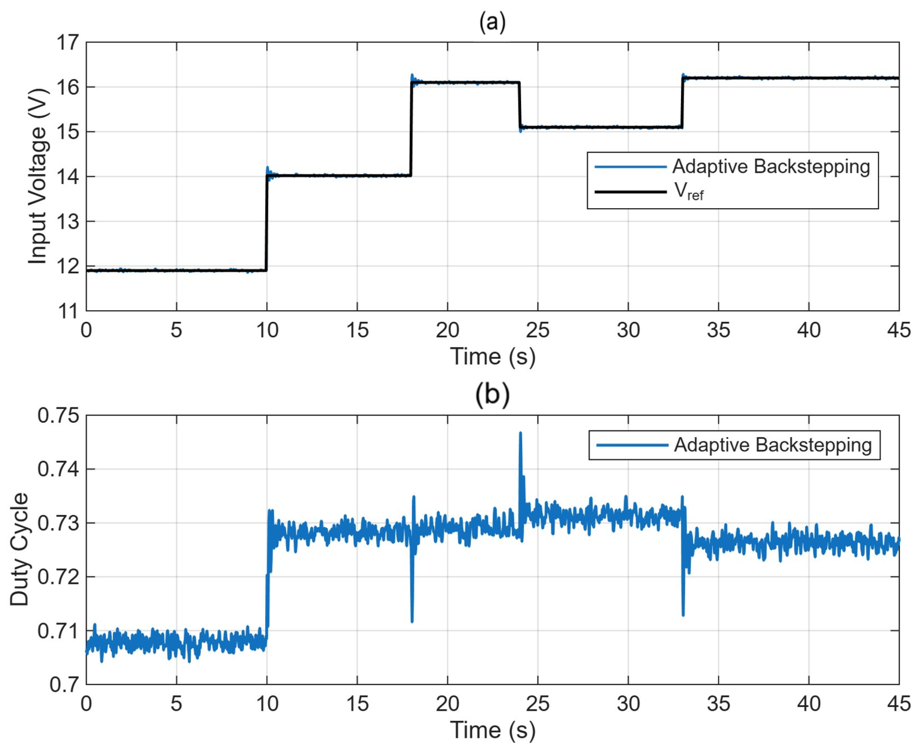
Figure 7 presents the internal response for the same experiment. In
Figure 7a, the PV input voltage is compared with the corresponding reference voltage. The results show that the measured voltage closely follows the imposed reference throughout all irradiance transitions, with small transient deviations and negligible steady-state error. This confirms that the controller can regulate the converter input voltage accurately under abrupt operating-point variations.
Figure 7b shows the corresponding duty cycle evolution. As expected, the control action is adjusted after each irradiance transition in order to drive the PV generator toward the new maximum power operating point. Although short transients are observed at the transition instants, the duty cycle rapidly settles to a stable value in each interval, without significant oscillations or instability. This behavior confirms that the power response in
Figure 6 is achieved through accurate voltage tracking and stable converter actuation.
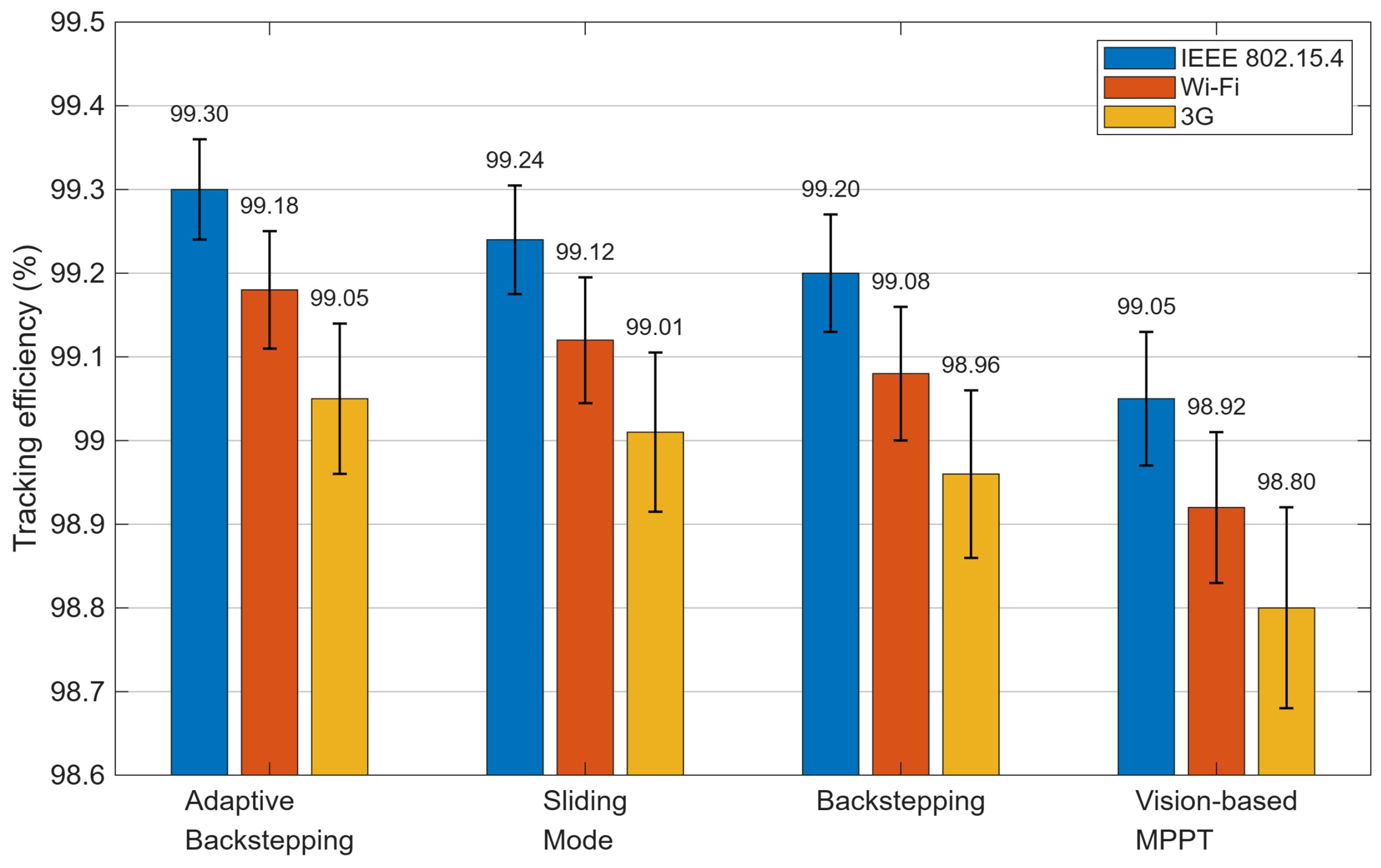
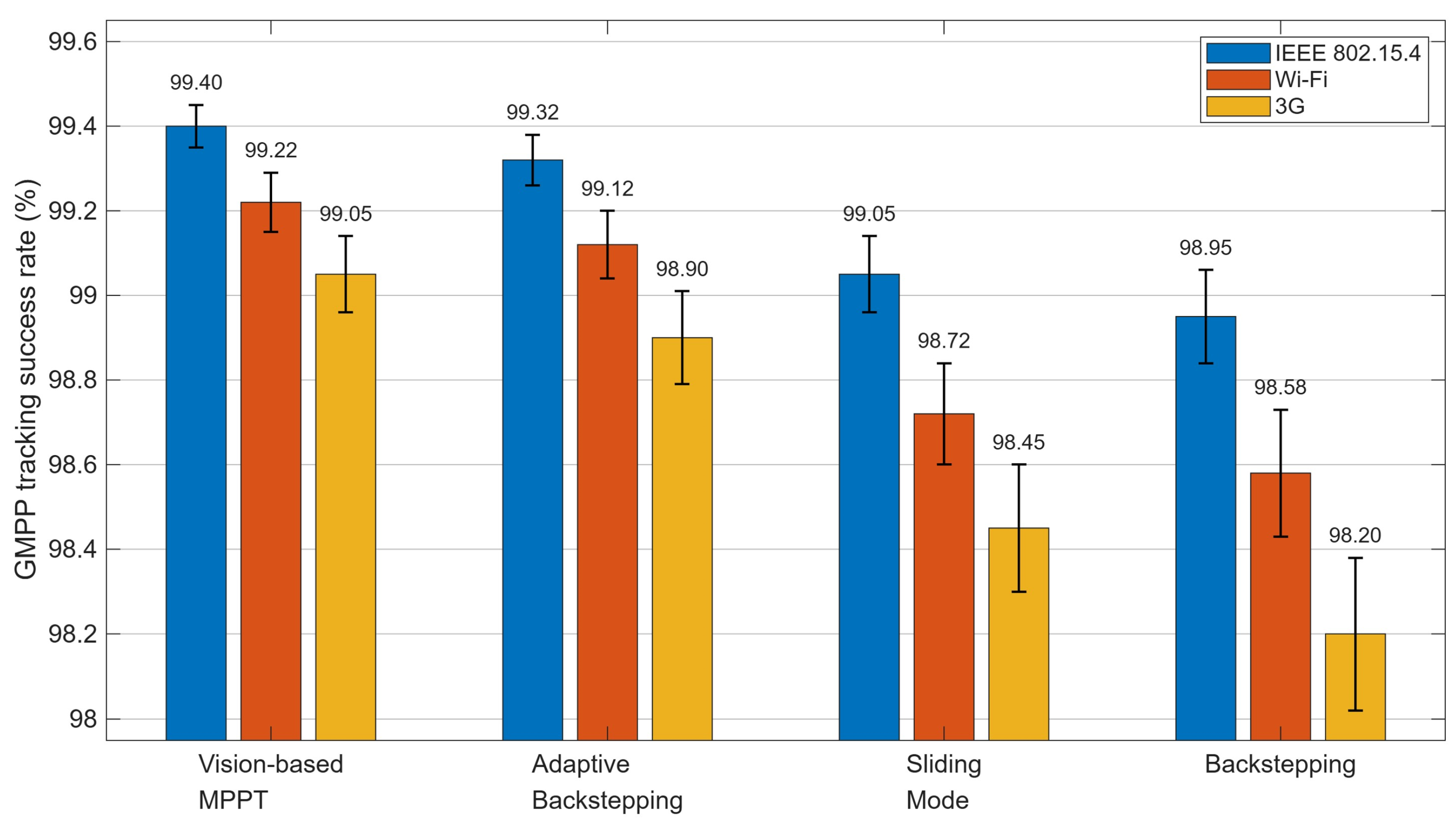
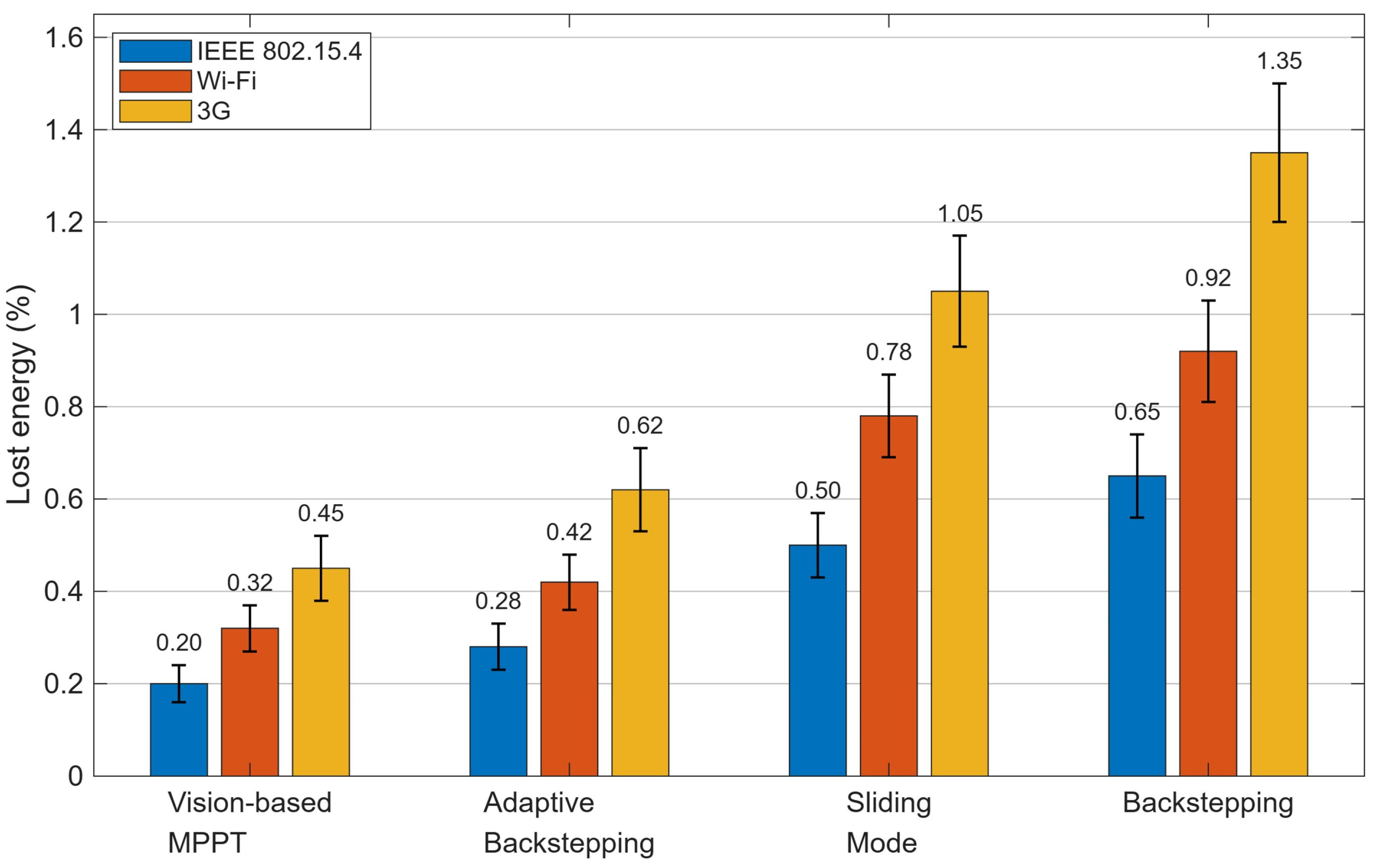
For each MPPT–communication configuration, the reported aggregated performance indicators were obtained from different repeated experiments under the same operating conditions. The values shown in
Figure 8,
Figure 9,
Figure 13 and
Figure 14 correspond to the mean results, while the error bars represent the standard deviation associated with the repeated measurements.
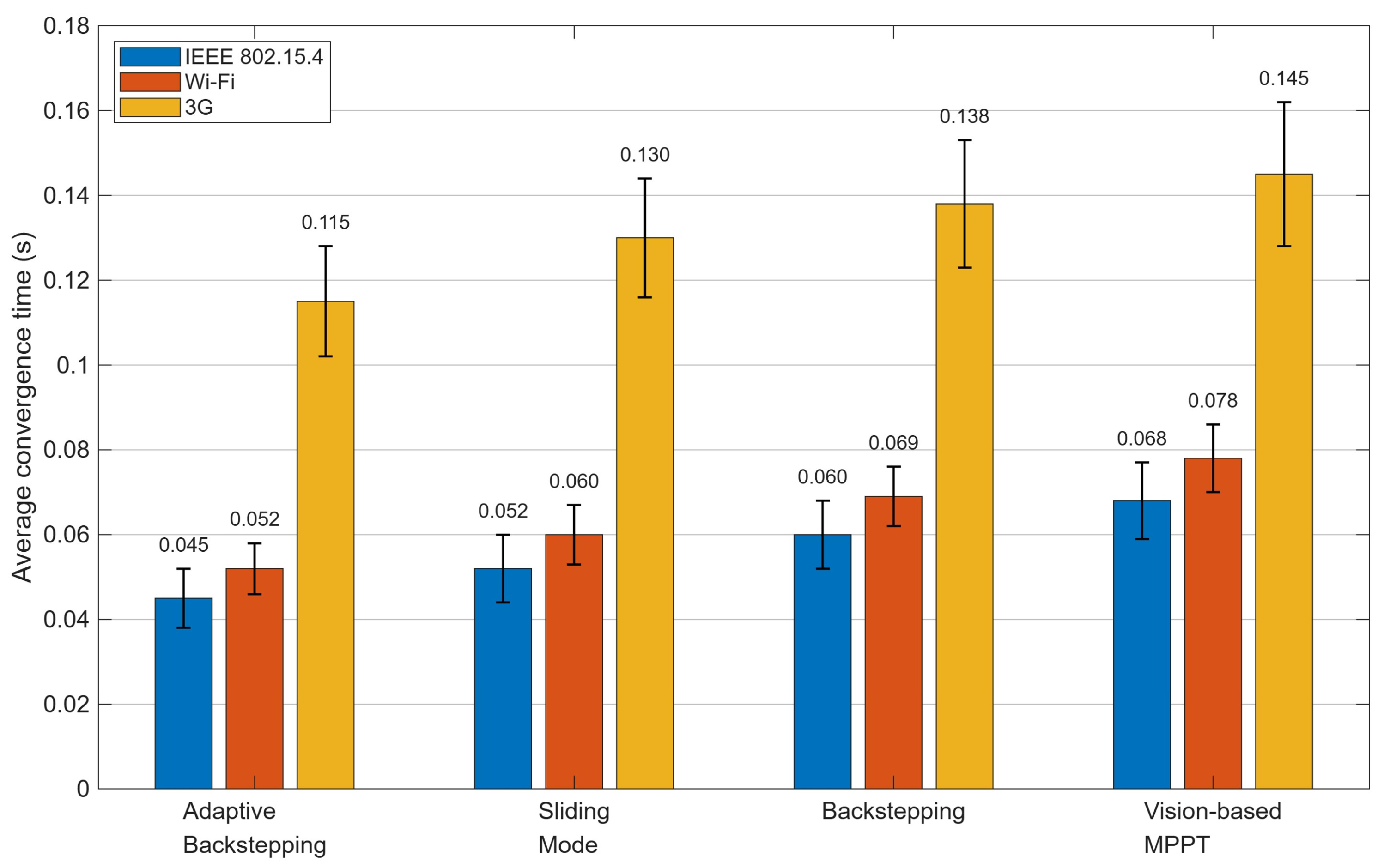
Figure 8 compares the average convergence time of the four MPPT strategies for the three evaluated communication technologies under uniform irradiance step variations. Adaptive backstepping consistently provides the shortest convergence time, followed by sliding mode control, conventional backstepping, and the vision-based MPPT. This ranking is preserved for IEEE 802.15.4, Wi-Fi, and 3G, indicating that the intrinsic dynamic properties of the control algorithm strongly influence the transient response. The superior behavior of adaptive backstepping is associated with its nonlinear structure and online parameter adaptation. Sliding mode control also provides a fast response because of its robustness, whereas conventional backstepping is more sensitive to parameter uncertainty. The vision-based method presents the longest convergence times under uniform irradiance because its main advantage lies in GMPP localization under partial shading rather than in minimizing single-peak transient response.
Figure 8.
Comparison of the average convergence time for the four MPPT strategies under the three evaluated communication technologies. Error bars represent the estimated standard deviation.
Figure 8.
Comparison of the average convergence time for the four MPPT strategies under the three evaluated communication technologies. Error bars represent the estimated standard deviation.
The communication architecture also affects convergence speed. IEEE 802.15.4 yields the lowest average values, Wi-Fi slightly higher values, and 3G the slowest response. This trend is consistent with the beacon-enabled operation and GTS access of IEEE 802.15.4 and with the higher delay of 3G. Adaptive backstepping reaches 0.045 s with IEEE 802.15.4, 0.052 s with Wi-Fi, and 0.115 s with 3G, demonstrating that the controller dynamics and communication timing jointly determine transient performance.
While
Figure 8 provides a quantitative comparison of the transient speed through the average convergence time, the convergence rate alone is not sufficient to assess the overall MPPT performance. For this reason,
Figure 9 complements the previous analysis by comparing the tracking efficiency. In agreement with the convergence-time results shown in
Figure 8, adaptive backstepping achieves the highest tracking efficiency, followed by sliding mode control and conventional backstepping, whereas the vision-based MPPT presents the lowest values under uniform-irradiance conditions. This behavior confirms the advantage of control strategies designed for fast electrical regulation under single-peak conditions.
Regarding the communication layer, IEEE 802.15.4 generally yields the highest tracking efficiency, Wi-Fi exhibits slightly lower values, and 3G provides the lowest performance in most cases. However, the differences are relatively small, and all evaluated configurations remain above 98.8%. Thus, the uniform-irradiance tests reveal more pronounced differences in convergence speed than in final tracking efficiency.
Figure 9.
Comparison of the tracking efficiency for the four MPPT strategies under the three evaluated communication technologies during uniform irradiance step variations. Error bars represent the estimated standard deviation.
Figure 9.
Comparison of the tracking efficiency for the four MPPT strategies under the three evaluated communication technologies during uniform irradiance step variations. Error bars represent the estimated standard deviation.
5.2.2. Partial Shading Scenarios (GMPP Test)
Controlled partial shading patterns were applied to the three series-connected modules. The selected shading profiles were designed to produce two- and three-peak P–V characteristics, following the same experimental rationale of [
18], where each module may operate under a different effective irradiance level. The partial shading conditions were generated under controlled experimental conditions using manually imposed shading masks to obtain repeatable irradiance mismatch among the three series-connected modules. Distinct shading patterns were considered in the comparative analysis, including both two- and three-peak P–V characteristics. In the vision-based configuration, the image-derived shadow intensity was converted into equivalent irradiance values for each module, providing repeatable and well-defined test conditions [
18].
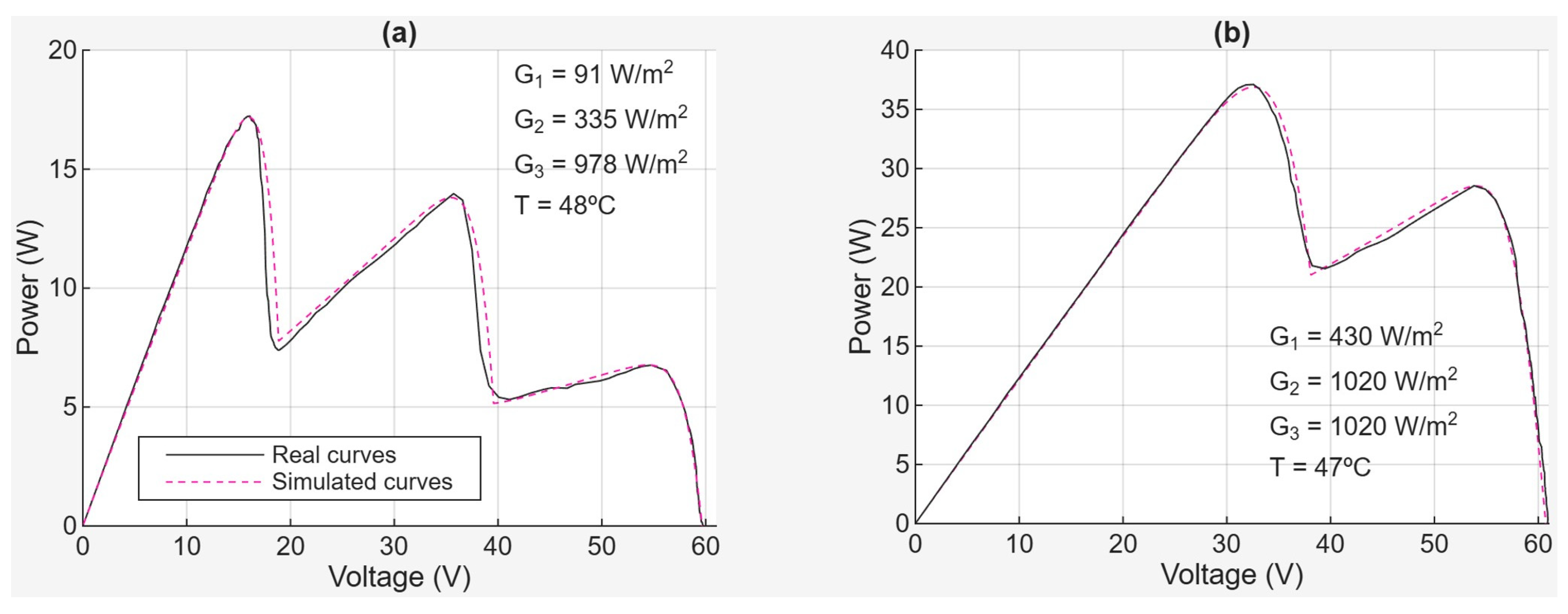
Figure 10 shows representative three-peak and two-peak P–V characteristics. In
Figure 10a, a strong irradiance mismatch generates three peaks, whereas the less severe distribution in
Figure 10b produces two peaks. The experimental and simulated curves show close agreement, supporting the adopted model. More importantly, the separated local maxima illustrate that an MPPT algorithm may converge to a non-global operating region and incur energy losses under partial shading.
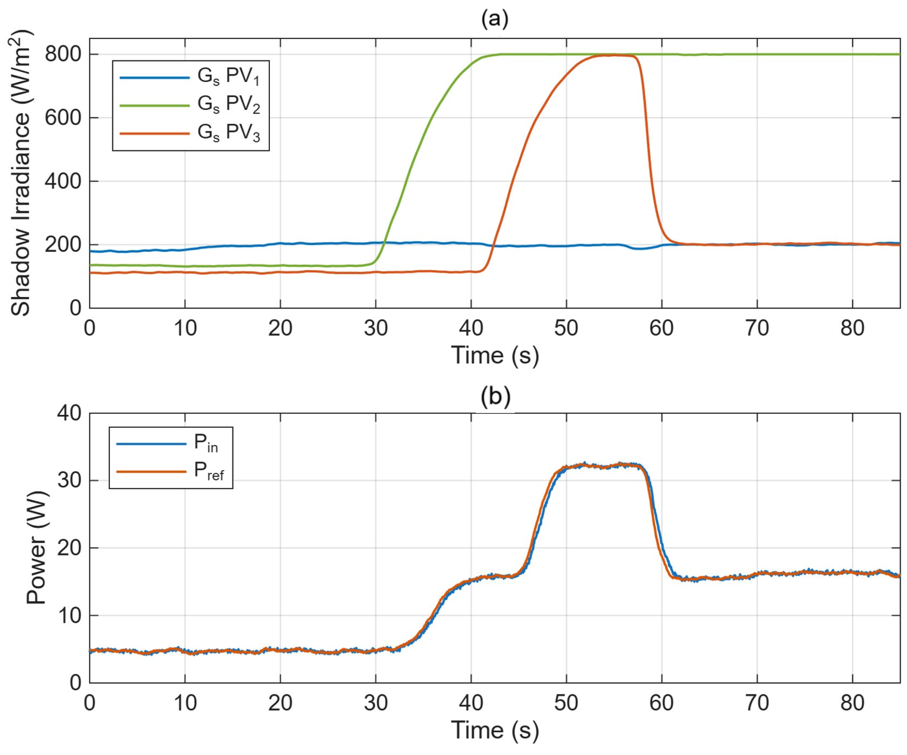
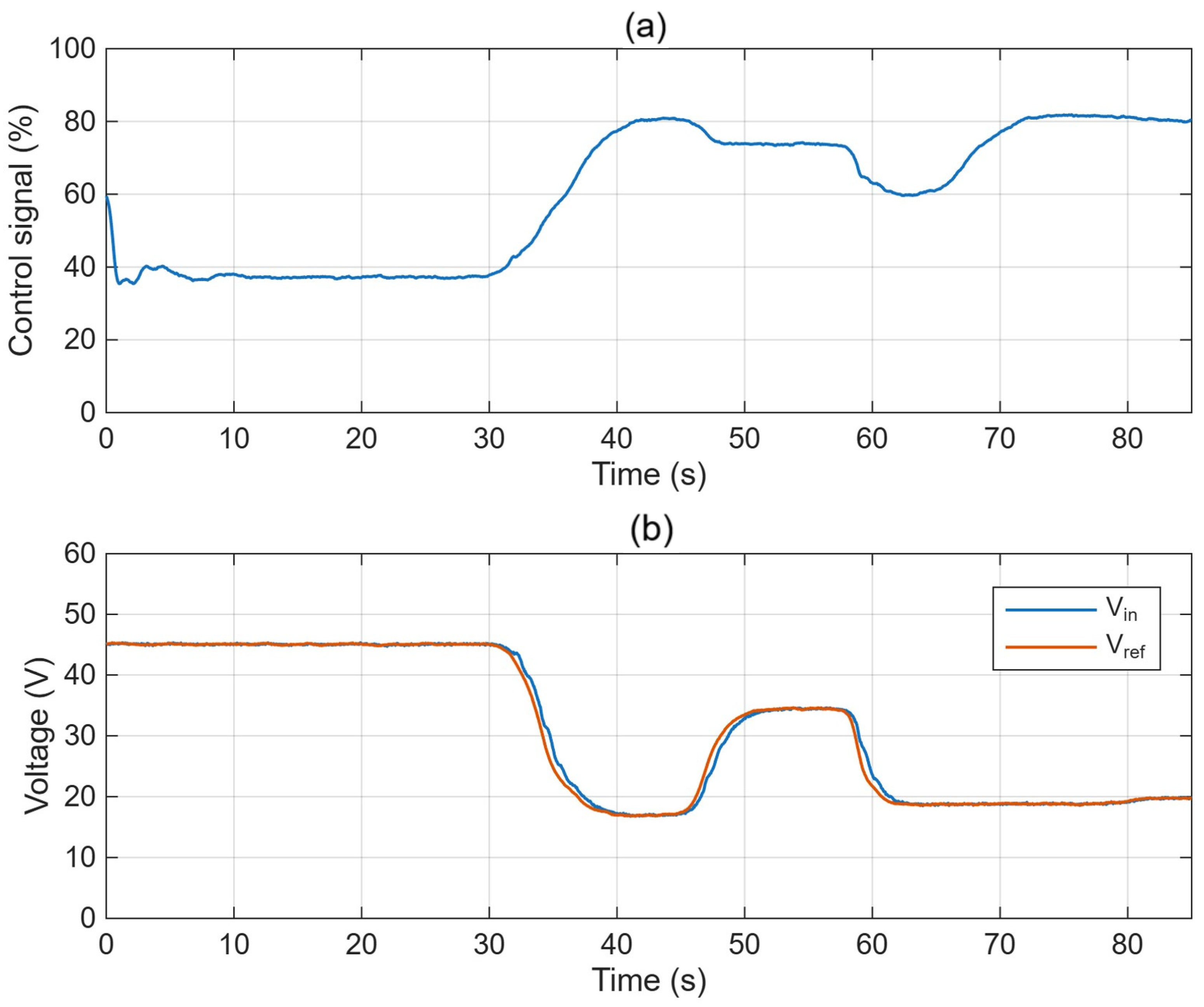
Figure 11 and
Figure 12 show representative time-domain responses of the vision-based MPPT. In
Figure 11a, the estimated irradiance of the three PV modules evolves according to the imposed non-uniform shading pattern, generating successive changes in the operating conditions of the PV string.
Figure 11b shows that the extracted input power follows its reference, with low steady-state deviation and limited transient mismatch. This confirms that the algorithm detects the irradiance redistribution and updates the operating target under changing multi-peak conditions.
Figure 12 complements the previous result by showing the internal dynamic response of the same experiment. The control signal in
Figure 12a is updated after each shading transition and remains stable within each interval. In
Figure 12b, the measured input voltage follows the reference while the operating point moves from approximately 45 V to 17–18 V, then to 33–34 V, and finally to 19–20 V. This result is particularly relevant, since it demonstrates that the controller can move the PV system from one local operating region to another in order to track the voltage associated with the GMPP, instead of remaining trapped around a local maximum. The good agreement between
and
confirms the effectiveness of the proposed control strategy in relocating the operating point under multi-peak conditions.
In contrast to the uniform-irradiance case,
Figure 13 shows that the vision-based MPPT achieves the best overall performance, followed by adaptive backstepping, sliding mode control, and conventional backstepping. This ranking indicates that, under multi-peak conditions, the ability to identify the region of the GMPP becomes more relevant than purely fast transient responses. The spatial information obtained from image processing reduces the probability of convergence to local maxima. Adaptive backstepping remains competitive because of its robust regulation, whereas sliding mode control and conventional backstepping lack an explicit GMPP-localization mechanism.
From the communication viewpoint, IEEE 802.15.4 provides the highest GMPP tracking success rates, Wi-Fi shows slightly lower values, and 3G yields the lowest performance. This trend is consistent with the shorter and more predictable timing of IEEE 802.15.4 and the larger delay and variability of 3G. The vision-based approach remains the best-performing method for all three communication scenarios.
While
Figure 13 quantifies the ability of each MPPT strategy to successfully locate the GMPP under partial shading, the success rate alone does not fully reflect the energetic impact of tracking errors. For this reason,
Figure 14 complements the previous analysis by comparing the percentage of lost energy for all MPPT–communication combinations.
Figure 13.
Comparison of the GMPP tracking success rate for the four MPPT strategies under the three evaluated communication technologies. Error bars represent the estimated standard deviation.
Figure 13.
Comparison of the GMPP tracking success rate for the four MPPT strategies under the three evaluated communication technologies. Error bars represent the estimated standard deviation.
Figure 14.
Comparison of the lost energy percentage for the four MPPT strategies under the three evaluated communication technologies during partial shading conditions. Error bars represent the estimated standard deviation.
Figure 14.
Comparison of the lost energy percentage for the four MPPT strategies under the three evaluated communication technologies during partial shading conditions. Error bars represent the estimated standard deviation.
The lost-energy results in
Figure 14 are fully consistent with the GMPP success rates shown in
Figure 13. Vision-based MPPT produces the lowest losses, followed by adaptive backstepping, sliding mode control, and conventional backstepping. This ranking confirms that the ability to correctly identify and maintain operation around the GMPP has a direct impact on the final energy. The superior behavior of the vision-based MPPT is attributed to the additional spatial information provided by the image-processing stage, which reduces the probability of convergence to local maxima and therefore minimizes the associated energy losses.
From the communication perspective, IEEE 802.15.4 provides the lowest lost energy values, Wi-Fi shows slightly higher losses, and 3G exhibits the worst performance for all MPPT strategies. When moving from IEEE 802.15.4 to 3G, lost energy increases from 0.20% to 0.45% for the vision-based method and from 0.65% to 1.35% for conventional backstepping. These values quantify the combined influence of GMPP-localization capability and communication timing on energy extraction under partial shading.
5.2.3. Communication Performance Characterization
For each communication technology, the end-to-end delay associated with the control loop was quantified. In the IEEE 802.15.4 WSN, the beacon-enabled superframe with guaranteed time slots (GTSs) provides bounded latency behavior suitable for closed-loop control, as previously implemented on the authors’ platform [
18]. Wi-Fi is affected by contention-based channel access, whereas 3G includes operator- and network-dependent routing.
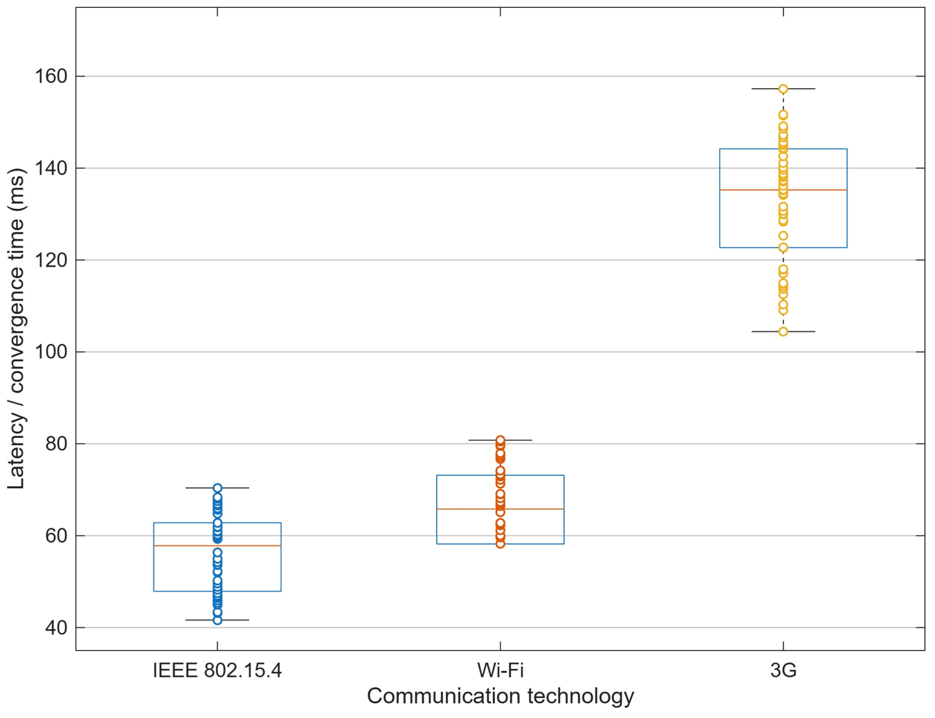
Figure 15 shows the distribution of the end-to-end latency measured for the three evaluated communication technologies. As expected, IEEE 802.15.4 exhibits the lowest median latency and smallest dispersion, which is consistent with its synchronized GTS-based operation and guaranteed time slots implemented in the WSN. Wi-Fi presents slightly higher latency values and a wider spread, reflecting the variability introduced by contention-based medium access. By contrast, 3G shows the highest latency levels alongside the largest variability, which is attributed to the additional network and routing delays inherent to this communication technology. Therefore, IEEE 802.15.4 provides the most favorable timing characteristics for closed-loop MPPT operation, whereas 3G is the least suitable.
Communication delay affects MPPT performance through delayed measurement delivery, slower control updates, and delayed duty-cycle transmission. During rapid irradiance or shading changes, these effects reduce the freshness of the control variables and may increase convergence time, tracking mismatch, and operation away from the GMPP. The measured latency trends are consistent with the communication characteristics summarized in
Table 2 and with the control-performance results reported above.
6. Discussion
The main contribution of this work is not the isolated validation of a single MPPT method or a single wireless architecture, but the unified experimental assessment of their interaction under common distributed PV operating scenarios. The results obtained in this study confirm that the performance of distributed PV MPPT systems cannot be assessed solely in terms of controller dynamics or communication latency. Instead, both layers interact and jointly determine the final energy performance. Under uniform irradiance conditions, where the P–V characteristic exhibits a single maximum, the dominant requirement is the fast and accurate regulation of the electrical operating point. In this scenario, adaptive backstepping provides the best overall behavior, reaching an average convergence time of 0.045 s with IEEE 802.15.4, compared with 0.052 s for Wi-Fi and 0.115 s for 3G, while all evaluated configurations maintain tracking efficiencies above 98.8%. These findings indicate that, under single-peak operating conditions, the dynamic properties of the nonlinear controller are the main differentiating factor, while communication delay acts as a secondary but still measurable source of performance degradation.
A different ranking emerges under partial shading conditions. Once the P–V characteristic becomes multi-peak, the key requirement is no longer only rapid convergence, but also the capability to identify the correct operating region associated with the GMPP. In this scenario, the vision-based MPPT clearly outperforms the remaining strategies in terms of GMPP tracking success rate and lost energy, followed by adaptive backstepping, sliding mode control, and conventional backstepping. This finding is fully consistent with the physical principle of the vision-based approach: by exploiting spatial information about the shading distribution, the controller is able to restrict the search region and reduce convergence toward local maxima. The energetic relevance of this advantage is directly reflected in the lost-energy results, which increase from 0.20% to 0.45% for the vision-based MPPT and from 0.65% to 1.35% for conventional backstepping when moving from IEEE 802.15.4 to 3G. Therefore, the results show that under partial shading, the ability to locate the GMPP becomes more important than purely fast electrical transients.
From the communication perspective, IEEE 802.15.4 emerges as the most suitable technology for closed-loop MPPT operation on the implemented platform. Its advantages are not limited to lower average delay, but also include lower dispersion, which is critical in control-oriented applications. The latency characterization confirms that IEEE 802.15.4 exhibits the lowest median end-to-end delay and smallest spread, Wi-Fi occupies an intermediate position, and 3G introduces the largest latency and variability. These characteristics are consistent with the convergence, tracking-efficiency, GMPP-success, and lost-energy trends observed in
Section 5, confirming that communication timing directly affects the achievable control quality when the wireless link participates in the closed loop.
An important implication of this study is that no single MPPT strategy should be regarded as universally optimal. Adaptive backstepping is the most appropriate solution when the dominant objective is to track quickly and accurately under uniform-irradiance or rapidly varying, single-peak conditions. By contrast, the vision-based strategy is the preferred choice when partial shading is frequent and reliable GMPP localization is the primary design objective. Sliding mode control and conventional backstepping remain technically attractive because of their robustness and implementation simplicity, but their comparative advantage becomes narrower when they are evaluated against adaptive estimation or external visual sensing. This means that the final selection should be made based on the expected operating scenario, available sensing infrastructure, acceptable computational burden, and communication constraints.
This work also suggests practical design guidelines for distributed PV systems. When local low-power networking is feasible, IEEE 802.15.4 provides the best balance among determinism, latency, and control support. Wi-Fi remains a viable alternative when higher bandwidth is required, especially for architectures that may benefit from richer sensing or supervisory information, although with a small penalty in timing performance. 3G can still be useful for remote monitoring and geographically dispersed installations, but its latency and variability make it less suitable for time-sensitive closed-loop MPPT tasks. Consequently, the best overall combinations identified here are adaptive backstepping with IEEE 802.15.4 for uniform-irradiance operation and vision-based MPPT with IEEE 802.15.4 for partial shading scenarios. These findings provide practical design criteria for distributed PV systems in which control performance and communication behavior must be considered jointly.
While local MPPT remains the preferred solution in many conventional PV converters and commercial inverters, communication-assisted architectures are relevant in distributed PV systems, modular generation units, experimental microgrids, and supervisory environments where sensing, coordination, or GMPP-oriented decision support relies on wireless links. The present work is therefore not intended to replace the conventional local-MPPT paradigm, but to quantify the influence of communication timing when the wireless layer is deliberately involved in the sensing–control architecture. The conclusions should consequently be interpreted for distributed and communication-assisted PV systems rather than as a direct representation of all conventional PV installations.
Recent studies have demonstrated the growing relevance of IoT-based PV monitoring and wireless-assisted control, although most focus on a single communication technology or MPPT implementation. Fernández-Bustamante et al. proposed a centralized MPPT architecture using LoRa [
28], Beltrán Castañón et al. developed a low-cost wireless PV monitoring system [
21], and Mimouni et al. reviewed IoT and machine-learning applications for MPPT, supervision, fault detection, and energy optimization [
19]. These contributions confirm the importance of communication-aware PV architectures but do not provide a unified experimental cross-comparison of multiple advanced MPPT strategies and wireless technologies under common operating conditions. The present study addresses this gap by evaluating four MPPT methods and three communication technologies using harmonized irradiance scenarios and common control- and communication-oriented metrics.
The results should be interpreted within the adopted experimental framework. First, validation was performed on a laboratory-scale distributed PV platform based on a three-module string, which enables controlled comparison but does not fully represent larger field installations. Second, although the PV power stage and irradiance scenarios were retained across the tests, the communication architectures employed different embedded acquisition and control chains. The reported differences therefore represent complete MPPT–communication implementation architectures rather than the isolated effect of the communication medium. Third, the communication assessment focused mainly on end-to-end latency and its effect on control performance; long-term packet loss, large-scale congestion, cybersecurity, and extended outdoor deployment were beyond the scope of this work. These limitations define the range within which the reported comparative trends should be interpreted.
For practical clarity,
Table 5 summarizes the relative suitability of the evaluated MPPT strategies under the main operating scenarios considered in this study. Overall,
Table 5 confirms that the optimal MPPT–communication selection is scenario-dependent: adaptive backstepping provides the most favorable behavior under uniform irradiance, whereas the vision-based approach is preferred under partial shading.
7. Conclusions
This paper presents an experimental comparison of four advanced MPPT strategies—backstepping, adaptive backstepping, sliding mode control, and vision-based MPPT—combined with three wireless communication technologies—IEEE 802.15.4, Wi-Fi, and 3G—on a distributed PV platform. The results show that MPPT performance depends not only on the control algorithm but also on the timing characteristics of the communication layer.
Under uniform-irradiance conditions, adaptive backstepping achieved the best overall performance, providing the shortest convergence times and highest tracking efficiency. In particular, it reached an average convergence time of 0.045 s with IEEE 802.15.4, compared with 0.052 s for Wi-Fi and 0.115 s for 3G. Under partial shading conditions, the vision-based MPPT showed the best results in terms of the GMPP tracking success rate and lost energy, due to its improved capability to identify the correct operating region under multi-peak P–V characteristics. Its lost energy increased from 0.20% with IEEE 802.15.4 to 0.45% with 3G, whereas conventional backstepping increased from 0.65% to 1.35%. Overall, IEEE 802.15.4 provided the most favorable communication support, Wi-Fi showed intermediate performance, and 3G was the least suitable option for time-sensitive closed-loop operation.
The optimal MPPT–communication configuration is therefore scenario-dependent. Adaptive backstepping combined with IEEE 802.15.4 is the preferred choice when fast and accurate tracking under uniform irradiance is the primary design objective, whereas vision-based MPPT combined with IEEE 802.15.4 is more suitable when reliable GMPP localization under partial shading is required. These conclusions are limited to the laboratory-scale three-module platform and the complete MPPT–communication implementation architectures evaluated under harmonized operating conditions. In conventional PV systems, communication-induced delays can generally be avoided by executing the MPPT control loop locally; consequently, the reported communication effects apply specifically to distributed and communication-assisted architectures in which the wireless link participates in the sensing–control loop.