This section provides answers to the research questions being explored in this paper. In this section qualitative data collected from the selected articles are analyzed and presented to give an understanding of deployment of ERS for the electrification of municipality’s e-buses.
3.1. Electrification of the Road Transport Sector
The transport sector currently accounts for about 23% of CO
2 emissions, and this is projected to increase to 50% by 2030 [
13]. Thus, the decarbonization of road transport can significantly contribute toward the decrease in CO
2 emissions in society. The electrification of road transport offers a promising path toward the reduction in CO
2 emissions [
11]. The electrification of road transport can be achieved by employing various approaches, such as the adoption of EVs via static charging (i.e., EV charging while being parked), power-to-fuel through the production of hydrogen or electro fuels as methanol and hydrogen (i.e., by utilizing fuel cells or electric power for onboard use in internal combustion engines), and the deployment of ERSs [
25,
26]. Therefore, the transport sector needs to substitute conventional fuels with low-carbon options such as EVs [
4,
26].
The adoption of EVs in society offers a potential solution for enhancing the sustainability of the entire road transportation sector [
4,
8]. However, batteries account for a major part of the EV cost, which is one of the challenges limiting the widespread use of EVs [
10]. Moreover, there is a need to support the required charging demands of using EVs such as e-buses at large-scale in municipalities [
19]. To address this issue, electrified roads (termed as ERSs) have been proposed as a viable solution that allows the transferring of electric power from the electrified road to EVs in motion using conductive or inductive (contactless) electric power transfer systems [
19]. ERSs are physical roads that enable dynamic electric power transfer from the roadway to EVs while the EV is stationary or in motion, providing the possibility for EVs to charge while driving. When connected to the ERS, EVs such as e-buses can either re-charge their batteries or use the electric power for propulsion [
10,
13,
27].
ERSs can supply electric power to electrify heavy-duty transports as they travel on the electrified road, thus reducing the need for large batteries [
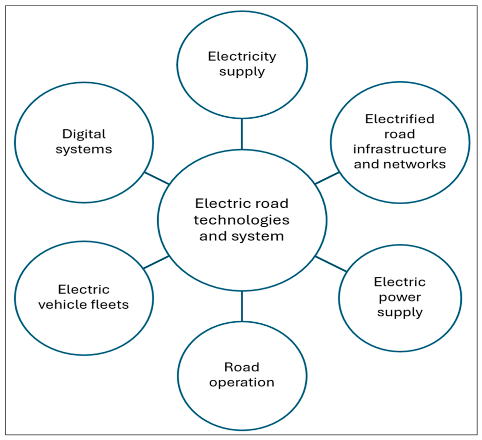
28]. According to the literature [
19], a basic ERS deployment comprises an EV charging system, the electrical power grid, and the network road infrastructure. However, full-scale deployment of ERSs comprises five main subsystems as seen in
Figure 2 and mentioned in prior studies [
28,
29].
In ERSs, electric power is supplied to the electrified road infrastructure and across the road network mainly via substations that transform high voltage to medium voltage. Electric power is transmitted via cables that supply electricity from the regional power grid to the electrified road infrastructure, connected to power boxes with rectifiers that convert electric power from alternating current (AC) to direct current (DC). The power boxes are usually placed every 40 m alongside the road (
https://www.eabel.com/distribution-boxes/ accessed on 31 July 2026). Electric power can be supplied to EVs via overhead wire transmissions or through the ground (road) [
28]. The deployment of ERSs can contribute to the decarbonization of the road transport sector, if they are supplemented by a renewable energy system. The fundamental principle of ERSs enables EVs to use electric power directly from the energy grid as they move along the electrified road, rather than depending only on battery storage [
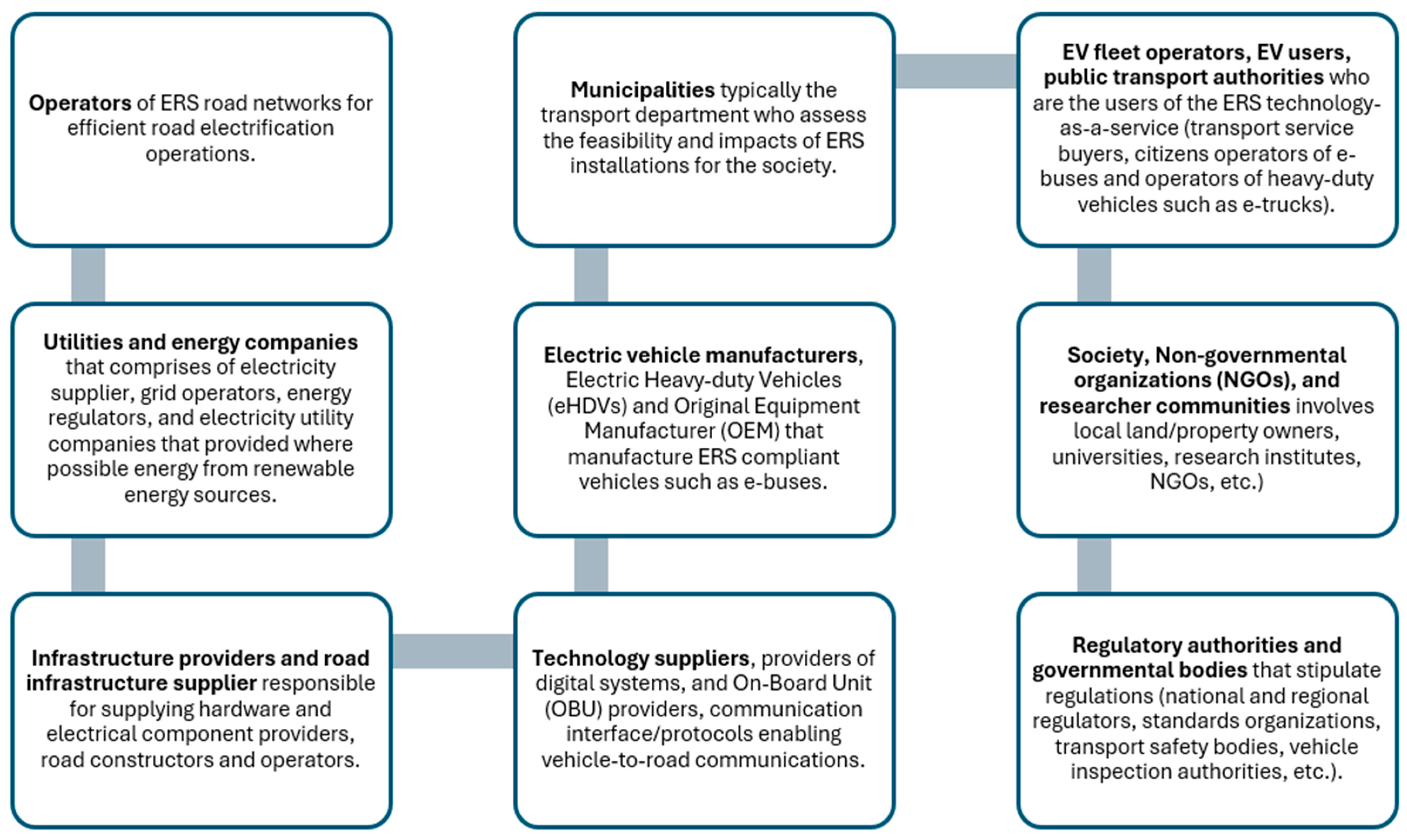
1]. Furthermore, the deployment of ERS technologies either as conductive or inductive is pioneered by a few stakeholders or actors as shown in
Figure 3.
3.2. Significance of ERS in Urban Context
In comparison to static charging systems, ERS technologies support dynamic charging, i.e., via continuous electric power transfer for propulsion and re-charging of the EV battery while driving [
30]. ERSs enable the possibility of decreasing the weight and size of the onboard battery and are particularly advantageous for e-trucks and e-buses [
26]. Municipalities intend to strategically deploy ERSs on main roads such that e-buses can be charged during use, irrespective of whether the bus is in static or dynamic mode. This means that e-buses can continuously be driven without having to stop to re-charge [
14]. This saves time and is also economical in eliminating the driving range problem of e-buses which stop charging while driving. Moreover, this creates a charging solution that enables e-buses to be fitted with smaller batteries, thereby reducing the battery capacity and density whilst minimizing the cost of ownership for municipalities [
14].
For municipalities, ERSs are suitable to be integrated on roads with a minimum of two or more lanes within the same direction, for example, dual carriageways, motorways, four-lane carriageways, and collision-free (barrier-separated) roads. This will allow one of the lanes to be utilized for road electrification. If the ERS malfunctions or stops working, there will be at least one open lane that is still accessible for incoming traffic [
27]. Furthermore, in urban environments, ERSs can be installed on major road networks that connect highly populated areas of the city. Thus, ERSs can be applicable for long-distance journeys within the city with speed limits of more than 50 km [
1]. This could substantially lower the size of the battery required for e-buses, since it would only require sufficient capacity to access the ERS infrastructure [
1].
For citizens, the deployment of ERSs can contribute to lower travel time and reduce the operational costs of vehicles [
31]. Thus, the deployment of ERSs can support e-trucks to become more energy efficient and sustainable. By electrifying main roads in municipalities, long-distance transport would be possible for e-trucks, delivering approximately 150 km while simultaneously allowing the use of small batteries in e-trucks on electrified road networks [
10], thereby benefiting e-truck operators, while investments in infrastructure and related maintenance costs are covered by the government. ERS deployment also fosters environmental and societal benefits such as lower ghg emissions [
31].
3.3. Application and Challenges of ERS for Charging Electric Buses in Municipalities
The electrification of the entire road transport has the potential to foster near-zero emissions of ghg towards carbon neutrality in society [
28]. While electrification of passenger cars is on the way, mostly through the adoption of electric cars, the electrification of heavy-duty transports such as trucks and buses is still limited [
28]. ERSs provide infrastructure that delivers the electrical power to efficiently charge heavy-duty transports using conductive or inductive (contactless charging systems) [
13]. ERSs provide the possibility to simultaneously recharge EVs, thus avoiding queues in charging stations [
32]. For charging municipality’s e-buses, ERS infrastructure can be sustainably implemented in cities [
13]. The use of ERSs can help municipalities to reduce the size and weight of the onboard vehicle battery in their e-buses without affecting the driving range, as compared to the use of static charging [
25].
To enable driving for about 4 hours, a city e-bus would need a battery with a capacity in the range of 600 to 800 kilowatt-hours (kWh). ERSs thus reduce the vehicle cost by reducing the battery size. However, evidence from a prior study [
25] revealed that there is a need for up-front investment costs to install large-scale infrastructure that can supply e-buses with electricity while driving. For example, commercial players such as Scania have tested the pantograph (
https://www.scania.com/group/en/home/newsroom/news/2021/Seven-more-Scania-trucks-to-be-delivered-as-German-e-road-expands.html accessed on 31 July 2026), equipped to electrify hybrid heavy-duty transports for use in ERS demonstrations in Germany and Sweden, equipped with 18 kWh battery packs [
9]. Likewise, the eHighway solution (
https://www.mobility.siemens.com/us/en/portfolio/rail-infrastructure/electrification/ehighway.html accessed on 31 July 2026) tested by Siemens employs a well-established method extensively utilized in electrified railways with a two-pole catenary system to provide an efficient electric power supply to the vehicle at motorway speeds [
2].
Generally, prior studies addressed ERS implementation related to technical integration, infrastructure needs, and environmental impacts, thus comprehensively assessing whether ERSs can be effectively deployed into existing road transport networks [
31]. Similarly, extensive research and tests have demonstrated the techno-economic feasibility of various ERS technologies across diverse regions. For instance, studies from the USA and Canada, as well as in European countries such as Sweden, Germany, Norway, the Netherlands, Turkey, and the United Kingdom (UK) have investigated the practical and economic challenges of deploying ERSs, highlighting the viability of this technology [
20,
31]. The deployment of ERS technologies can disrupt existing road structures, e.g., for the overhead catenary lines, the infrastructure constructed in the road structure and electrical wiring, drainages, etc., can interrupt existing driving conditions [
27]. Thus, there is a need to investigate how to provide electric power supply transversely from the roadside without causing damage to existing road structures [
27].
Although the adoption of e-buses in municipalities offers promising technology that contributes to sustainable transportation, the adoption of e-buses is still faced with some drawbacks such as their higher procurement cost, longer charging times and limited driving range when compared to traditional buses [
18]. In addition, there are issues related to cost-effective business models [
12,
25,
33], specifying technology standards, and being able to accommodate business and technological changes in society [
25,
34]. Also, there is a need to successfully integrate ERS technologies into the existing road infrastructure [
13], as ERS technologies such as conductive rail/in-road or on-road conductive technology require periodic maintenance operations in clearing debris from the rail, checking joint sealing, and snow/ice clearing with special equipment [
27].
While prior studies have mainly investigated the technical aspects of ERSs [
10], the techno-social–economic aspects have not been well addressed in the literature. Moreover, prior studies have examined standardization relating to ERS components such as the vehicle, electric power supply, and road infrastructure [
29]. However, this current study will go further to investigate standards which are important for communication between different subsystems as shown in
Figure 2. This will enable seamless communication between road operations for the control energy management system, EV user information, access control, and fees and billing management. To address these setbacks, there is a clear need to examine the techno-social–economic implications of ERS deployment in municipalities [
31]. This includes considering the environmental and institutional factors required to support the development of inductive and conductive technologies for the dynamic charging of e-buses.
3.4. Review of ERS for Electric Vehicle Charging Technologies
ERS technologies are projected to be deployed on roads and highways connecting cities; thus, it is required to evaluate physical location of the road and how electric power will be transferred to the entire road networks [
18,
32]. Therefore, in urban environments, ERSs are deployed as either “stationary charging” or “dynamic charging”. Stationary charging refers to charging vehicles while parked at charging stations, whereas dynamic charging introduces the possibility of charging the vehicle while it is in motion [
17]. A few stationary and dynamic charging solutions are being demonstrated at different levels of readiness as reported in the literature [
15].
But over the last decades, research that promotes the adoption of stationary charging infrastructure for both cars and trucks has received considerable attention, while dynamic or inductive charging has received less attention [
17]. Although ERSs can be deployed either via conductive or inductive technologies, to date full-scale deployment of ERSs across public roads in cities has been mostly limited to conductive systems [
25]. Existing technologies for inductive charging of EVs such as e-buses are substantially less developed as compared to conductive charging for both overhead lines and rail [
32]. ERS-based dynamic charging is deployed as either conductive (via overhead catenary lines or via conductive rail/in-road or on-road conductive, roadside conductive and road-bound conductive), and in-road inductive (via wireless ground level power supply) [
2,
17,
35]. Both the inductive and the conductive rail solution can be deployed to supply electric power to conventional road transport vehicles (i.e., electric cars, e-buses, and e-trucks, except for motorcycles).
Conductive charging provides higher power (hundreds of kilowatt (kW)) as compared to inductive charging, whereas inductive charging by design galvanically isolates the vehicle from the electric power supply, thus improving safety. In the conductive approach, safety in electric power transfer is more challenging to manage compared to the inductive approach due to exposed live electrical components which are inevitable [
15]. Overall, conductive ERS technologies offers two main solutions for transferring electric power from the electrified road to the vehicle through overhead catenary lines connected to a pantograph installed on top of the vehicle and via a conductive rail installed in-road or on-road on top of the road that transfers electric power to the vehicle through a mechanical pick-up arm situated under the vehicle [
25].
Conductive charging technologies significantly differ from each other in several aspects including installation cost, functionality, and environmental impact; the overhead conductive technologies can only be deployed by high vehicles, for example, e-trucks and e-buses, while in-road conductive technology and inductive charging can be utilized by electric cars [
10], although conductive and inductive technologies require that the vehicle has a supplementary source for propulsion, such as a small battery, an internal combustion engine or fuel cell. This is required as not all sections of the road can be electrified such as segments of the road network that have high traffic flows or sections like interceptions or bridges that may be challenging to electrify. Moreover, as only one lane of the road is electrified, the vehicle needs to have another source of propulsion for overtaking or driving on the non-electrified lane. Also, vehicles need not to be totally dependent on the electric power supply from the ERS as this increases the resilience of vehicles in addressing potential malfunctions or power failures [
10].
Each of the types of conductive and inductive technologies are discussed in the subsequent sections.
3.4.1. Overhead Conductive Technology
Overhead transmission is implemented using conductive-based technology that connects to the vehicle via a type of transmission line such as a pantograph [
26]. Also, overhead conductive technology is presently the most advanced type of ERS as this technology has been developed based on years of experience from trains, trams and trolley vehicle development [
10,
32]. Overhead conductive technology is the most developed ERS, providing operational prototypes, but lacks a high-traffic end-to-end system. Overhead conductive technology enables efficient power transmission for electrifying heavy-duty transport, ensuring charging and propulsion of vehicles simultaneously without affecting the road surface [
31]. In overhead conductive technology, a pantograph is mounted on the roof of the e-truck to connect to the overhead electric power cables analogous to the technique employed in railways. It offers a robust and proven charging mode that does not have a direct impact on the existing road network and structure [
36]. Overhead conductive technology comprises different infrastructures, e.g., the support masts which are made of steel connected with a concrete foundation and longitudinal safety barriers which are also required to be installed along the roads [
36]. Overhead conductive technology was mainly marketed by Siemens in the eHighway project which was demonstrated in partnership with the Swedish Transport Administration in 2016 (as demonstrated outside the city of Gävle in Sweden) [
28,
36].
Furthermore, there have been several other demonstrations across Sweden, Germany, and the USA [
32]. Thus, the overhead line solution currently has the highest Technology Readiness Level (TRL) of 8 following years of advancement and numerous successful test trials in Sweden, the USA, and Germany [
2]. The eHighway conductive catenary system comprises overhead power lines with a height of about 5 meters (m) above the road surface. In the eHighway project, every 50 m along the roadside verge there are support masts coupled with a cantilever that holds the power lines [
36]. The existing catenary overhead line solution in its current design is most compatible with e-buses and e-trucks due to the elevated positioning of the catenary equipment [
25]. However, one disadvantage of overhead conductive charging is that this technology cannot be used by electric cars [
31,
32]. Another challenge with catenary overhead lines is that this technology uses a large number of materials. For example, large masts need to be built along the road verge which may have an impact on the existing road structure if positioned or installed too close to the road or in the case of erosion-prone soils [
27].
The overhead cables may in turn create unsafe conditions during winter conditions as a build-up of ice and snow could later fall on incoming vehicles. There is a possibility that the masts constructed within the roadside may require extra safety barriers to protect drivers in case of disruptions such as accidents [
27]. Also, the overhead line solution would likely become much more convenient and cost-effective for deploying charge-in-motion for heavy-duty transports [
2]. Electric power is supplied via medium-voltage substations connected to the necessary equipment (such as transformers and grid connection, switchgear, rectifiers, and inverters). This helps to provide the highest-efficiency solution suitable for charging and propelling heavy-duty transports, such as e-buses and e-trucks [
2]. This enables electric power to be transmitted directly from the overhead catenary lines via an inverter to the electric motor, thus reducing energy losses via the battery. This solution is suitable both for rigid and articulated heavy-duty transports and can be used by e-buses to provide continual operation on electrified roads [
2,
3].
However, overhead conductive technology has a significant visual effect on highways and mostly requires periodic maintenance due to wear and tear from friction between the electrical components [
31]. Overhead catenary lines have limited challenges related to access (including road pavement maintenance), which is easier in comparison to other conductive systems (such as in-road conductive solutions). This is because the pavement does not require installation of hardware fitting or modifications [
2].
3.4.2. In-Road Conductive Rail Technology
Rail or in-road conductive technology is another type of ERS technology that supplies electric power through a physical pick-up that is connected to an electrified rail in the road [
28]. In this conductive technology, electrical power is supplied through an electric rail in the road, analogous to subways [
10]. The rail-work is used for conductive transmission of electric power from the electrified roadway to vehicle [
32]. This technology has been demonstrated in the city of Lund and outside the city of Stockholm in Sweden [
28]. In Sweden, companies such as Elonroad and Elways are working with several rail concepts. Similarly, Volvo is collaborating with the French company Alstom on adapting such technologies to power urban railways to electrify heavy-duty transport. For example, Elways is testing a two-kilometer stretch of conductive in-road electric rail from the Arlanda cargo terminal [
32], where they have developed and installed an in-road electric rail within the road structure to transfer electric power via a pick-up installed beneath the vehicle [
36].
The rail infrastructure installs an isolating plastic on the conductive metal with a top cover of steel. The rail measurement is about 148 millimeters (mm) high and 144 mm wide with about 3–5 mm fitted beneath the driving lane. The rails are planned to be fitted within reach of each electric power distribution box; these are stationed within 1500 mm of each other [
36]. This ERS approach provides several advantages for electrifying roadways as it can serve EVs of different sizes with different electric power requirements, although this technology is faced with a few challenges related to the operation and maintenance of rail equipment that requires space in the asphalt with other construction elements. These challenges are mostly visible during winter conditions created by ice, snow, frost, and salt [
32]. The in-road conductive technology is faced with other issues that result in raising the surface profile of the carriageway, as changes in the surface profile can be considered as a major risk to other road users such as motorcyclists [
3].
3.4.3. On-Road Conductive Rail Technology
The on-road conductive rail offers a versatile and usable charging technology that is compatible with all vehicle types, thus enabling simultaneous propulsion and charging of vehicles [
31]. This ERS technology comprises a rail that is attached to steel plates fastened to the road surface every 1.5 mm. The rail in the ramp is bolted to or fastened to the road surface [
36]. The rail equipment is mainly made of copper, aluminum, and isolators which have a life span of about ten years. Also, the rail can resist roughness, unevenness, and up to 4 to 5 centimeter (cm) deep potholes. Although it has a low visual impact, this technology requires extensive road modifications which decrease the road lifespan and further increase possible safety risks [
31]. The on-road conductive rail can be affected by meteorological factors which can cause system failures. Also, friction between electrical components may result in wear and tear, while the maneuverability of the vehicle is slightly restricted [
31]. The on-road conductive rail was demonstrated in 2020 in a new test site in Lund, Sweden [
36]. Also, conductive rail technology uses electrified rails with different friction levels applied to the adjacent road surfacing. To ensure safety for all road users, the skid resistance of the rails must meet safety requirements for road surfacing across different road types [
3].
3.4.4. Roadside Conductive Rail Technology
Roadside conductive systems deploy side charging where an arm is positioned to the side of the vehicle. This requires lower maintenance and installation, making this ERS technology less complex to operate in highways, although roadside conductive systems are quite dangerous for cyclists and pedestrians [
14].
3.4.5. Inductive Charging Technology
Inductive charging technology enables the transfer of electric power from coils via magnetic induction, analogous to a transformer [
18]. Inductive charging transfers electric power from the “transmitter coil” or “the primary coil” (sending coil) embedded under the road to the “receiver coil” or “secondary coil” (pick-up coil) fitted inside the vehicle “wirelessly” without any wired connection between road infrastructures and EVs [
3,
10,
25,
26,
36,
37]. Induction technology has been employed for wirelessly transferring energy in households such as for induction cookers and for wireless mobile phone charging [
37]. Inductive charging can be deployed by all types of EVs with reduced visual impact and minimal friction between electrical components, thus enhancing the maneuverability of EVs [
31]. Basically, the deployment of inductive charging via wireless electric power transfer for EVs is based on either inductive power transfer (IPT) or capacitive power transfer (CPT) technologies [
36].
IPT wirelessly transfers electric power magnetically between two coils (the transmitter coil and receiver coil). The transmitter coil oscillates at high frequency, thereby creating electric power transfer. The oscillation by IPT creates electromagnetic fields (EMFs) [
36]. In contrast, the CPT uses the electric fields to transfer electric power between different metal plates. CPT has reduced cost due to its light weight. In comparison to IPT, it has lower eddy-current losses. But CPT is best suited when electric power transfer is needed for shorter distances. CPT is less effective for transferring electric power to EVs while in motion [
36]. IPT has been demonstrated outside the city of Visby in Gotland, Sweden [
28,
36], where coils are fitted within the constructed road beneath a surface layer of asphalt. Then electric current is induced between the copper coils (for the transmitter coil), in the roadway and a receiving coil installed inside the EV [
36]. The charging of the vehicle’s battery is activated when the vehicle connects to the electrified road network and the vehicle switches to the battery when it returns to a non-electrified section of the roadway [
37].
However, inductive charging is faced with some issues such as high retrofitting costs for road infrastructure. IPT is also faced with lower electric power transfer efficiencies; thus, IPT may not be able to provide the constant electric power required to propel and recharge heavy-duty transports [
9]. Another challenge relates to energy losses during electric power transfer within the electromagnetic field, with the potential effects of electromagnetic radiation from vehicle components [
27,
31], although researchers such as Flores-Gandur [
31] mentioned that IPT provides economic and social benefits by enabling wireless charging, thus minimizing costs, addressing anti-misalignment capabilities, decreasing emissions, enhancing efficiency, and promoting environmental sustainability [
31]. On the contrary, another study from [
37] highlighted that it is expensive to build and maintain inductive charging as it costs approximately
$1 to
$2.2 million United States Dollars (USD) to pave an induction road in a remote environment. Irrespective of these challenges, IPT offers a forward-looking charging solution that seamlessly integrates driverless cars, thus supporting the development of a more efficient and accessible transportation system for the future.
3.5. Deployment of Inductive Power Technology
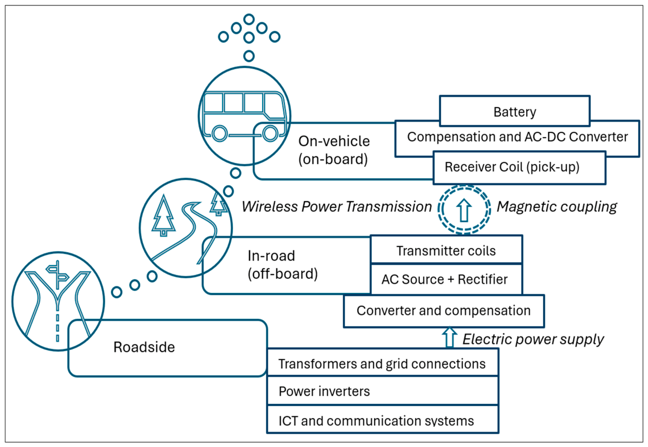
In IPT technology, electric power from the power grid is converted to high-frequency alternating current (AC) power to produce a varying “magnetic field” in the transmitter coil, which is picked up by the receiver coil in the vehicle. The magnetic field generates an induced voltage on the receiver coil resulting in the flow of electric current on the receiver coil, hence enabling inductive transfer of electric power. This enables contactless transfer of electric power across a variable air gap [
3]. Generally, inductive charging comprises three key components as seen in
Figure 4.
As illustrated in
Figure 4, the “roadside” components include transformers, grid connections, power inverters, information and communications technology (ICT) equipment, and communication systems [
3,
13,
38]. The roadside components supply electricity to the transmitter coil segment automatically when a compatible vehicle (e.g., e-bus) travels at a certain speed along the electrified road when the vehicle is detected [
3]. To start the inductive charging of the receiver coil, the EV passing over the transmitter coil induces the electromagnetic current between the coils, triggering the transfer of electric power. Also, the “in-road” components comprise transmitter coils (usually copper-litz turnings wired with a ferrite core and a multi-strand wire used to conduct AC) and electric power cables placed under the road surface [
3].
Typically, “on-vehicle” components encompass a receiver coil (also denoted as the pick-up unit), the control electronics, hardware and software (e.g., digital systems such as the onboard unit (OBU)) [
39]. Vehicles such as e-buses must have electric drive components such as an electric motor, heating, ventilation, and air conditioning (HVAC), and battery [
3]. Therefore, depending on the type of EV (e.g., e-bus), electric power can directly propel or charge the vehicle battery via wireless power transmission (WPT) as seen in
Figure 4 [
13]. WPT refers to an electrical system that can efficiently transmit electric power from one point to another via the earth’s atmosphere or the vacuum of space without the use of wires or via a cordless medium [
13].
Additionally, as seen in
Figure 4, inductive charging usually consists of onboard equipment installed under the e-bus’s chassis and an off-board electrical power equipment delivery device installed externally within the roadway [
13]. The off-board equipment mainly comprises the power supply unit that provides a properly regulated “direct current (DC) output voltage” via a “rectifier”. It also includes a “converter” that offers high output frequencies, combined with capacitance to achieve resonance with the transmitter coil that decreases the switching loss. It comprises “transmitter coils” that are connectively coupled with the “receiver coil”, which comprises conductive coils, ferrite cores with a backing plate [
13]. This enables the onboard part of e-buses to pick up high-frequency AC current through magnetic coupling that is changed into the DC current needed to charge the vehicle battery, as seen in
Figure 4 [
13].
3.6. Factors That Influence the Integration of Inductive Power Technology
Electric road technologies and energy systems such as inductive power transfer are currently being implemented and demonstrated across different projects [
40]. Regardless of the maturity of inductive power technologies and systems for static charging of EVs and in consumer electronics, the widescale adoption of these technologies is faced with legal, political, technological, economic and social challenges when this technology is used for dynamic charging of e-buses in municipalities [
18,
30], as seen in
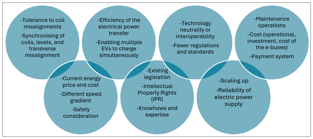
Figure 5.
As presented in
Figure 5, inductive power transfer for e-buses in municipalities is faced with issues related to energy systems, business models, and technical complexities [
26]. Therefore, there are technological factors that need to be addressed for inductive power transfer to become feasible [
3]. There is a need for better vertical and lateral tolerance to coil misalignments, since the positioning of the coils at the same relative spot while e-buses are in motion is challenging. Also, there is a need for a high electric power density for the secondary coil to lessen the added weight to e-buses [
3,
18]. For example, several systems, either IPT or CPT solutions, have issues in synchronizing with primary coil segments with the secondary coil in e-buses [
41]. This synchronization is affected by the speed of the vehicle, communications speeds, signal switching, and lateral alignment of the electrical components, all of which can impact the rate electric power transfer and overall efficiency of the electrical power transfer for municipal bus applications [
3,
41].
Presently, inductive systems are mainly capable of transferring electric power when EVs are traveling with a speed of around 80–100 kilometers per hour (km/h), suitable for e-buses and e-trucks which have a highway speed of 90 km/h in most regions [
3]. But inductive systems may not be suitable for passenger vehicles which would typically travel on highways at up to 120–130 km/h [
3]. However, inductive systems are known to be faced with low power ratings, usually around 20 kW, which are typically suitable for passenger vehicles. For recharging and propelling heavy-duty transports such as e-buses, the electric power efficiencies, levels, and transverse misalignment need to be enhanced [
3,
41]. Another important challenge that needs addressing is the ability to enable multiple EVs to charge simultaneously on a coil section or single road segment. This challenge is related to the communication speeds of the coils and their synchronization [
3]. Furthermore, technology neutrality [
32] or interoperability is another issue that influences the ability of ERS technologies to recharge EVs irrespective of the type of e-bus. Achieving full-scale deployment of inductive power transfer interoperability has become a functional requirement as this relates to the communication protocols used by e-buses to interact and share information with the ERS infrastructure [
3]. Currently, interoperability does not exist in either inductive or conductive systems, limiting the ability to enable efficient electric power transfer from the energy grid to the ERS infrastructure to e-buses.
The development of inductive power transfer requires the need for standardization which is important for achieving interoperability, competitiveness, and compatibility with e-buses [
29]. For inductive power transfer, standardization is still in an early phase [
29]. As such, there are fewer known regulations and standards that provide a clear path for ERS interoperability [
3]. However, there are some standards mentioned in the literature [
29], such as IEC 61980177 (
https://webstore.iec.ch/en/publication/22951 accessed on 31 July 2026), supporting wireless power transfer (WPT) systems which focus on supporting the standardization for inductive electric power transfer for EVs but do not provide full deployment guidelines. Another standard is ISO/IEC 15118198 (
https://driivz.com/glossary/iso-15118/ accessed on 31 July 2026), which enables vehicle-to-grid (V2G) communication for road vehicles, specifically involving communication between EVs and charging equipment [
3]. Thus, standardization for inductive power transfer is still in its preliminary phase [
29].
The findings from the literature indicate that there are other issues faced that limit the power levels and efficiencies of inductive power technologies and systems such as intellectual property rights (IPRs), installation depths (similar to the air gap allowed between the coils), ERS geometry (for inductive coil dimensions and size), system architectures, and electrical and electromagnetic requirements for e-buses [
3,
41]. Similarly, other issues include installation and maintenance of primary coils and electrical equipment, the impact of the installation on the road infrastructure during maintenance, knowhow, and expertise [
3]. Additionally, there are issues related to the state of competing ERS charging technologies, electrical equipment requirements, scaling up, electric power supply and reliability, as well as environmental, social and economic impacts for viable business cases and operational costs needed for operating e-buses [
3,
26]. Additionally, widescale electrification of a municipality’s transport sector through the adoption of e-buses with inductive power transfer via dynamic charging will place a new demand on the power grid [
26]. Hence, the deployment of inductive power transfer may increase the energy load which may result in high strain on the electricity supply, depending on when (the time of consumption), how, and to what extent EVs are charged [
26].
Electrified roads require periodic inspection, monitoring, and maintenance activities which are critical [
42]. The installation of the coils on the road may result in surface cracking, de-bonding effects of stones, and possibly permanent deformation. Winter maintenance operations such as the removal of ice and snow could limit wireless power transfer [
42]. Electrical cables used in catenary technology might need to be “de-iced” as well [
27]. Moreover, cost is perceived as one of the factors that influence the selection of ERS solutions. The findings from the literature [
30] mentioned that the deployment of ERS can bring about cost savings [
30].
Similarly, evidence from the literature mentioned cost reductions due to the downsizing of e-buses’ battery packs in relation to the cost incurred for installing charging equipment [
18]. Likewise, the cost of the vehicle compatible with inductive power transfer is an important factor to consider by municipalities when assessing which ERS technologies are suitable to be adopted [
1,
4]. Similarly, investment costs are needed to implement inductive power transfer for road electrification. A study by UC Berkeley conducted in 1990 revealed that a cost of about 1,000,000 US
$/km was needed per ERS lane [
41]. Also, additional costs such as maintenance costs may be needed for the expansion of the power grid ensuring that the required electric power is supplied to the road [
18,
37].
Inductive power transfer requires the provision of payment systems or gateways that manage fees paid by e-buses that use ERS infrastructures, as there are issues related to how these payment systems should be implemented to support multiple roles and actors [
37]. These payment systems can be installed in the vehicle to support payment and tax calculation according to the current energy price and tariffs [
37]. Additionally, the electricity fee set by ERS road network operators includes the investment costs of the road network operator [
43]. Thus, the cost stipulated by ERS road network operators specifying the fees municipalities will pay for using inductive power transfer may impact the deployment of ERS technologies.
Inductive power transfer systems should be able to cope with different speed gradients from different vehicles, allowing heavy-duty transports to charge at maximum speed limits (90 km/h), thus accommodating passenger vehicles which are moving at a faster speed [
3]. In addition, health and safety issues are important aspects to consider [
41]. Safety consideration in inductive power transfer relates to the supply of electric power from the road to the vehicle via high-frequency magnetic fields. More knowledge and experience are required to ensure the operational safety, stability, and reliability of ERS technologies. Also, the risk assessment of electric safety in inductive power transfer is scarce [
35]. Thus, there are fewer studies that assess operational faults or hazards regarding electric safety, concerning touch current, when an individual gets in physical contact with an EV’s chassis when the vehicle is connected to the electrified road [
35].
The deployment of inductive power transfer for e-buses in municipalities is dependent on existing legislation that may act as a barrier due to social concerns such as legislative acts on public and private roads. Regulations are stipulated to ensure that municipalities are protected in the face of technological or societal changes [
3]. These legislative acts aim to safeguard the planning, design, construction, operation, and maintenance of public and private roads, ensuring seamless and safe traffic for road users in supporting the operations of e-buses. In general, this involves vehicle regulation concerning the approval of e-buses and e-trailers, as well as requirements for road safety, fire safety and the natural environment [
32]. Therefore, the widescale deployment of inductive power transfer requires complying with relevant legislation for assessing necessary approvals of vehicles in close cooperation with the national road authorities [
32].
Moreover, regulations for deploying inductive power transfer do not relate only to transport but also to land-use procurement and competition, consumer rights, energy supply, environmental protection, health and safety [
3]. Thus, legislation may differ between countries due to different road administrations [
3]. Furthermore, the use of EMF to achieve inductive power transfer may interfere with the communication infrastructure used by road workers, emergency services, or even the health devices (such as pacemakers) of drivers, passengers, or pedestrians. Similarly, there is less legislation that governs the use of EMF emissions for wireless electric power transfer in pavement structures [
3].
Another notable issue is associated with road construction challenges faced by inductive power transfer. This is because ERS technologies such as inductive power transfer use coils that are completely embedded within the road structure. Thus, it is important to have prior knowledge of the road construction and sub-layers before excavation of the road due to large rocks with different thicknesses along the road construction layers, both vertically and laterally. This impacts the vertical distance between the road coils and the vehicle receiver coils that aids efficient energy transfer. Also, moisture could increase the loss of electric power in pavement materials [
27]. Hence, the evenness and structural characteristics of the road construction layers are important elements that should be assessed at the ERS planning stage [
27]. Additionally, there is a need to assess the transfer efficiency for wireless electric power according to prior studies, which varies between 70 percent and 95 percent. This is because inductive power transfer induces small electric fields that cause electric power losses due to slight conduction and electric polarization in the surrounding materials.