Article

From BIM2BEM: A Model-Driven Environment for Dependable Building Energy Models

1
Construction Management and Tunneling Unit, Department of Structural Engineering and Material Sciences, University of Innsbruck, 6020 Innsbruck, Austria
2
Department of Computer Science, University of Innsbruck, 6020 Innsbruck, Austria
3
Energy Efficient Building Unit, Department of Structural Engineering and Material Sciences, University of Innsbruck, 6020 Innsbruck, Austria
*
Author to whom correspondence should be addressed.
Energies 2026, 19(15), 3565; https://doi.org/10.3390/en19153565
Submission received: 26 June 2026 / Revised: 23 July 2026 / Accepted: 27 July 2026 / Published: 29 July 2026
(This article belongs to the Section G: Energy and Buildings)

Abstract

The growing demand for energy-efficient buildings highlights the need for reliable Building Energy Modeling (BEM) to accurately predict and optimize performance throughout a building’s life cycle. However, current BEM workflows are often hindered by media breaks, tool interoperability challenges, and inconsistent model properties, leading to unreliable simulations. This work presents a novel model-driven environment designed to provide reliable, trustworthy building models used for BEM. Our approach utilizes model-driven engineering to enable seamless tool integration at the model level and provides automated enhancement of Building Information Models (BIM) with BEM-specific properties. Furthermore, we incorporate a model checker to ensure the correctness, consistency, and semantic integrity of these BEM-specific properties within the BIM model. The proposed environment integrates seamlessly with existing engineering workflows while facilitating efficient model hand-offs. The effectiveness and user acceptance of our proposal are demonstrated through a case-based evaluation and the Technology Acceptance Model. In practice, implementing this developed workflow and model-driven environment, designed for users in engineering and architecture, results in a consistent and reliable BEM for energy simulation tools, yielding reasonable simulation outcomes through default values. Additionally, this scalable approach lends itself to further applications, such as life cycle assessment tools or enriching models with company-specific content.

1. Introduction

Buildings, throughout their entire life cycle, consume too much energy, accounting for a significant portion of global energy consumption, with estimates suggesting that they account for around 40% of total energy use and nearly 30% of greenhouse gas emissions worldwide [1]. As urbanization accelerates and the global demand for buildings rises, the need for energy-efficient buildings becomes more urgent. This places energy efficiency in buildings at the forefront of strategies to combat climate change and ensure sustainable resource use. Building Energy Modeling (BEM) and dedicated building energy simulations have emerged as a vital tool for predicting and optimizing energy performance during the design, construction, and operational phases of buildings [2]. By simulating energy use, BEM informs decision-making and helps to identify opportunities for reducing energy consumption [2,3,4,5] and can lead to significant reductions in both operational energy use and associated carbon emissions [6].
However, the accuracy of BEM in accurately predicting energy performance is frequently called into question [7]. One major challenge derives from media breaks, i.e., disruptions in information continuity between tools [8] and stakeholders involved in the modeling and simulation process [3,4], a prime cause for loss of dependability, and increased risk of error. These media breaks are often caused by manual model exchange, incompatible modeling formalisms and file formats, and superficial Building Information Modeling (BIM) models, leading to errors and inaccuracies during BEM simulations [9], hence undermining the dependability of BEM-based predictions [10,11].
The dependability of BEM is further compromised by the growing complexity of building control systems [12]. Modern buildings often integrate diverse technologies, such as IoT-based sensors, advanced HVAC systems, and renewable energy sources, making accurate modeling increasingly challenging [6,13]. Ensuring consistency in and across models and maintaining interoperability among tools through well-defined model transformations are thus crucial for establishing continuous workflows that yield dependable outcomes. Existing methods, however, frequently fall short in addressing these issues [8,14,15] (cf. also Section 2). Addressing the aforesaid issues requires both robust and thus carefully designed solutions that enhance interoperability between BIM and BEM tools to improve BEM’s dependability. Our work investigates systematic strategies to achieve dependable energy efficiency prediction, which are crucial for minimizing building energy consumption and environmental impact.
A promising approach to tackling the aforesaid issues lies in the application of model-driven engineering (MDE). MDE excels at managing complexity, delivering automation, and tailoring engineering processes to different domains by capitalizing on domain- and platform-specific modeling, model checking, model-based tool integration (MBTI), and model-driven generation [16]. In the process, MDE has established itself as a prime approach to improve system dependability [17]. At the same time, through the application of BIM, the construction domain started its transition to object-based modeling, model-based collaboration, and network-based integration [18,19]. This approach to building modeling is blatantly similar to software-based modeling using, e.g., UML or SysML, by also employing semantically rich, typed structures that represent domain knowledge through objects and their associations [20]. Following this MDE-aligned line of thought, BIM offers the foundation by providing a digital representation of a building’s physical and functional characteristics and the structured data needed to enhance BEM. Recent advancements in BIM2BEM workflows demonstrate that BIM can serve as a reliable foundation for enhancing the accuracy and dependability of BEM simulations [3,4,8,15]. Complementary to that, MDE is based on the premise that consistency and continuity across modeling (cf. BIM) and simulation (cf. BEM) platforms can be ensured through systematic transformations and MBTI.
The successful delivery of integrated BIM2BEM workflows, however, provides additional benefits, such as supporting the implementation of predictive maintenance and building retrofitting strategies. For example, a continuous BIM2BEM workflow can help identify parts of a building that require energy-efficiency upgrades, allowing for more informed decisions about retrofitting and enhancing long-term energy savings [6,8,15]. This approach is not only beneficial during the initial design and construction phases but also throughout the operational life cycle of a building (cf. legacy buildings [21]), ensuring that energy optimization efforts remain consistent and effective.
Consistent with the above, we explore the application of MDE as a systematic approach to improving BIM2BEM and, consequently, BEM’s dependability. MDE employs formalized modeling techniques, tool integration, and automation to ensure consistency, eliminate redundancies, manage complexity, and reduce errors. Our synergistic application of MDE and BIM forms the basis for improving BEM’s dependability. Specifically, our work proposes a model-based tool environment that includes
  • MBTI to establish integrated workflows across different phases of BIM2BEM;
  • Model checking to identify and address inconsistencies within BIM models before BEM-based simulation;
  • Model augmentation and model-to-model transformations to automate the creation of simulation-ready BEM models from BIM models, thereby minimizing human error as well as enhancing dependability and reproducibility through automation.
In addition to the need for consistently augmented models in terms of BEM-related properties, which can be provided through the proposed workflow, we also evaluate our proposal using the Technology Acceptance Model (TAM) [22], performance benchmarks, and reliability to demonstrate its usability, acceptance, and technical feasibility. Our work demonstrates that the application of MDE holds the potential to significantly improve the dependability of BEM by ensuring accurate, consistent, and automated energy simulations. By addressing the challenges of media breaks, data inconsistencies, and tool interoperability to establish integrated, model-driven BIM2BEM workflows, our approach contributes to more sustainable and energy-efficient building designs and offers a promising pathway toward reliably predicting and reducing the energy consumption and environmental impact of buildings.
This work is the result of a three-year interdisciplinary research effort (cf. Section 2, BIM2BEM-Flow) among civil engineers, industry stakeholders from construction engineering, and computer science (specifically, software engineering).
The main objective of this research is to minimize energy consumption in buildings throughout their life cycle. Since the most significant opportunities for improvement are found in the initial phases of projects, the emphasis is placed on the early stages of the planning process, using energy simulations. To facilitate this, digital building models will be employed because they adopt a holistic approach that encompasses much of the necessary information and represents current best practices. It is essential to engage a wide range of stakeholders within the planning process to ensure low barriers to adoption and maximize uptake.
Article Organization: Section 2 outlines the problem context of our work alongside discussing the main challenges and our contributions. Section 3 analyses the requirements of our research problem. Section 4 presents our solution proposal. Section 5 discusses the implementation of our solution proposal. Section 6 evaluates our proposal using the TAM and investigates its reliability and performance. We discuss our results in Section 7 and conclude in Section 8 with an outlook on future work.

2. Background and Contributions

This section situates our work within the context of BIM2BEM integration and model-driven engineering, outlines dependability gaps in current BEM practice, and summarizes the challenges addressed by our contributions.

2.1. BIM2BEM-Flow

BIM2BEM-Flow [23] is an interdisciplinary research project designed to connect Building Information Modeling (BIM) with Building Energy Modeling (BEM) by creating a continuous model-driven workflow. One of the central challenges addressed by the BIM2BEM-Flow is the current fragmentation between BIM and BEM tools, which often impedes seamless data exchange and slows down energy-related decision-making. BIM2BEM-Flow improves the interoperability of diverse tools utilized in the construction industry for seamless model and data exchange for thorough energy efficiency planning, as outlined in its core research objectives:
  • R1: Enable energy performance assessments in all design phases based on a projected energy target corridor.
  • R2: Manage BEM-specific properties in a standardized and tool-independent manner that facilitates interoperability.
  • R3: Allow intuitive and user-friendly configuration of tool environments without requiring extensive technical expertise.
  • R4: Ensure the system’s applicability throughout the entire building life cycle, including the operational phase (e.g., performance monitoring).
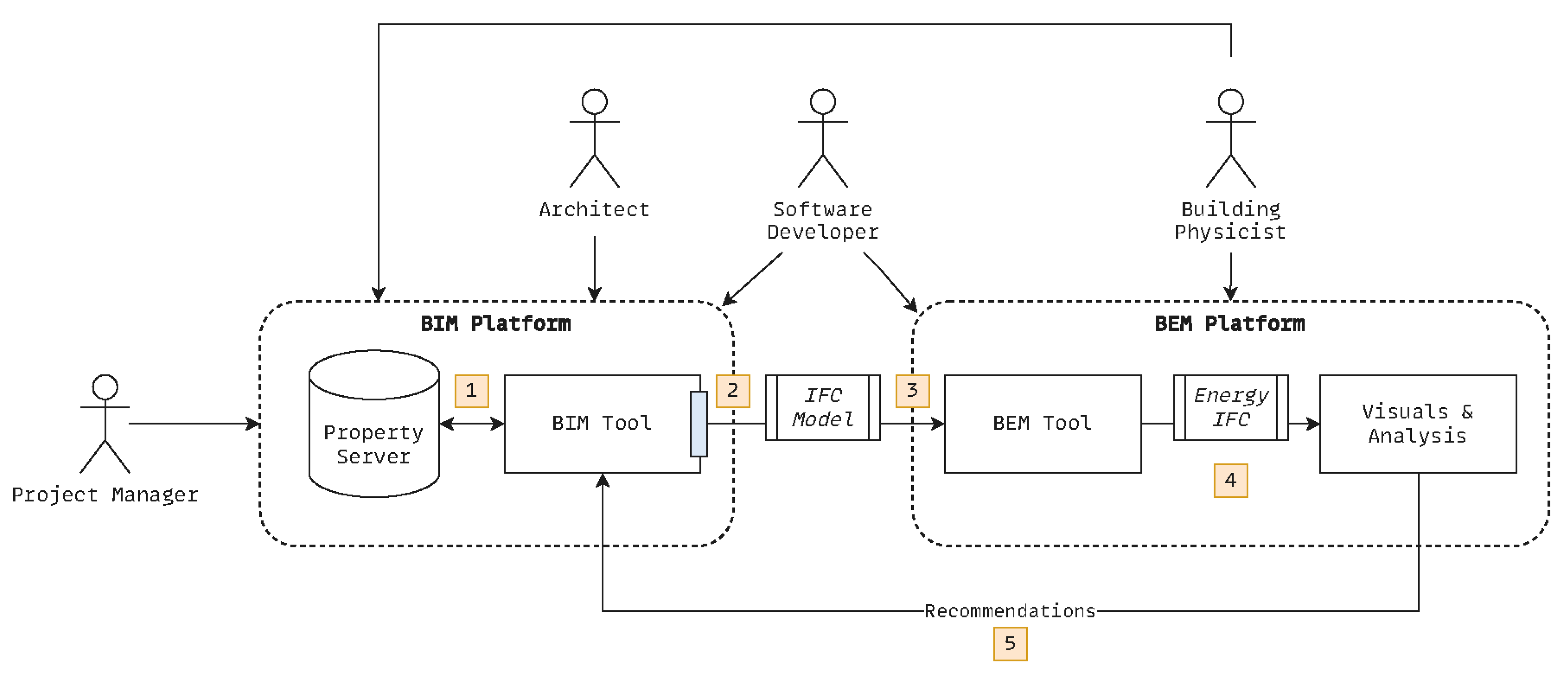
BIM2BEM-Flow’s conceptual workflow, as shown in Figure 1, illustrates a stepwise integration of BIM and BEM systems using the Industry Foundation Classes (IFC) [24], and highlights the data flow across tools and platforms following a five-step protocol:
  • Define and synchronize properties on a property server and integrate them into the BIM tool.
  • Export properties to IFC using a dedicated exporter (blue rectangle) that ensures interoperability with BEM systems.
  • Import the IFC model into the relevant BEM tool for energy simulation.
  • Export the simulation results into a structured format for downstream analysis.
  • Visualize and compare simulation results with both (i) a pre-defined energy target corridor to generate optimization recommendations, and (ii), different designs to identify an optimal design.
This structured process defines and supports an iterative, transparent design approach where energy-related feedback becomes continuously available, enabling data-driven decisions from the very beginning of the planning process.
BIM2BEM-Flow prioritizes a model-driven approach that autonomously augments and converts BIM models to enhance tool interoperability (cf. MBTI). This advancement is essential for allowing users, such as architects, building physicists, and planners, to create energy assessment procedures with flexibility and without necessitating in-depth knowledge of technical standards, data and model formats. BIM2BEM-Flow integrates established standards such as the IFC for data sharing and applies model and data transformation techniques to execute conceptual workflows efficiently.
In summary, BIM2BEM-Flow focuses on the systematic development of a model-driven tool environment to enable more efficient and streamlined BIM2BEM workflows than traditional methods (cf. Section 2.3). The project aims to facilitate the widespread implementation of BIM principles in energy-efficient construction practices and advance reliability engineering by offering tools and methodologies that improve the dependability of BEM throughout the building life cycle. BIM2BEM-Flow thereby prioritizes a model-driven approach that autonomously augments and converts BIM models to enhance tool interoperability (cf. MBTI). By abstracting technical complexity, domain experts can define energy assessment procedures without requiring detailed knowledge of underlying standards or data formats. BIM2BEM-Flow employs known standards such as the IFC and EnergyIFC [25] for model and data exchange, and applies model and data transformation techniques to execute BIM2BEM workflows efficiently and reliably.

2.2. Model-Driven Engineering

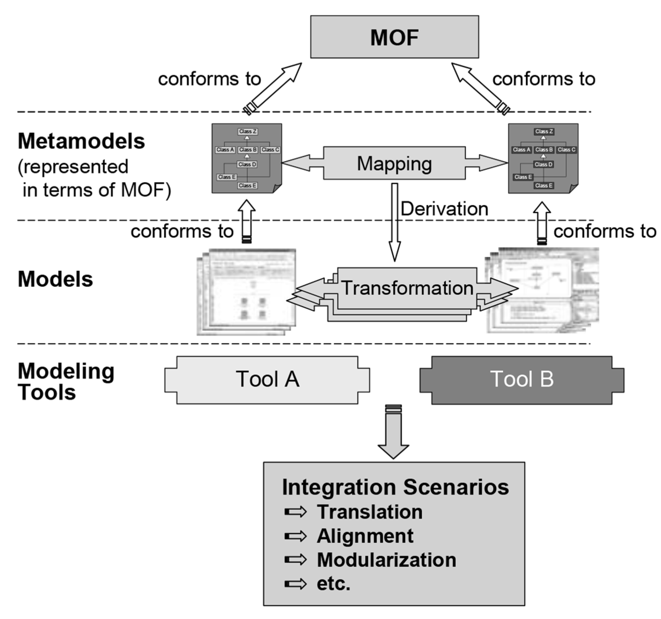
Model-driven engineering (MDE) is a well-established discipline in software engineering treating models as first-class citizens by establishing the engineering process atop these models [26,27,28]. MDE specifically excels in taming complexity both of the development process and the system under development [29,30]. MDE thereby enables the establishment of automated engineering workflows [31,32,33] for increased efficiency, consistency, and reliability. The establishment of such automated engineering workflows in turn substantially capitalizes (i) on the notion of model transformations, i.e., the automated translation of source models into target models with different representations [34,35], and (ii) model-based tool integration [36], i.e., the application of model transformations to transform models between different tool representations to resolve media disruptions at the modeling level, a common and critical constraint in establishing integrated model-based engineering workflows in BIM [37]. Figure 2 outlines this interplay between model transformations and MBTI for systematically and reliably bridging gaps at the model level.
Through the use of domain-specific modeling languages (DSML) [38], MDE offers the possibility of tailoring engineering workflows to alternate domains, e.g., construction engineering [39]. In essence, the use of a DSML breaks down to either engineering full modeling languages with high domain resemblance, e.g., construction engineering and involved trades [32,40], or specific language constructs that allow for extending existing modeling approaches [8,32,33,41]. This showcases the effectiveness of integrating established practices from MDE into BIM (and BEM) to advance efficiency, consistency, and reliability.
MDE has gained significant traction as a means of improving system reliability by promoting automation, consistency, and traceability throughout the engineering process [42]. As Brambilla et al. outline, MDE uses abstract, formal models as the core development artifacts to facilitate early detection of errors and enable rigorous model transformation and validation [20]. This model-centric approach aligns naturally with reliability engineering, where managing complexity and ensuring robustness are critical. Slaatten et al. further demonstrate how MDE can embed fault-tolerance strategies into system architectures, illustrating the integration of reliability-enhancing mechanisms directly within the modeling process [43].
In practice, MDE has supported structured reliability assessments through formal methods such as SysML-based modeling and fault analysis tools, e.g., by extending modeling languages to include reliability properties or through supporting scenario-based failure analysis during early design stages [44,45]. Hoefig et al. employed Component Fault Trees within MDE to streamline and scale safety and reliability assessments in industrial settings [46]. Beyond fault tolerance, MDE also supports the convergence of safety and security engineering. A systematic mapping study by Bagnato et al. highlights how MDE contributes to the joint handling of safety and security concerns and provides structured methodologies and reusable models across application domains [47].
Apart from that, various model-driven approaches have been proposed to support the early-stage analysis of non-functional properties such as reliability in complex systems. Bocciarelli and D’Ambrogio presented a method for modeling and predicting the reliability of composite web services using a model-driven technique that enhances standard service descriptions with quality-of-service annotations [48]. Similarly, Cortellessa et al. proposed a model-driven methodology to support reliability evaluation of component-based systems by transforming annotated UML models into representations suitable for quantitative assessment [49]. Ciancone et al. introduced KlaperSuite, an integrated model-driven tool set for analyzing performance and reliability of component-based architectures [50]. Their framework leverages an intermediate language, KLAPER, to automate the transformation from high-level design models to formal analytical models to support scalable and repeatable reliability assessments throughout the development life cycle. Collectively, these works underscore MDE’s powerful role in establishing dependable and repeatable engineering workflows in complex domains.

2.3. Dependability in BEM

Despite its promises, BEM still falls short in that simulation results do not align with measured energy consumption, which naturally results in the energy performance gap [51,52]. Reeves et al. [53] conducted a comparative study of measured annual energy consumption in two academic buildings in the United States against simulations produced by three commonly used tools: IES, Ecotect, and Green Building Studio. Their findings revealed substantial discrepancies, with simulation tools underestimating the actual monthly energy consumption by margins ranging from 28% to as high as 95%. Although other studies report less pronounced differences, Raji et al. [54] still identified deviations of up to 15% using DesignBuilder. Elnabawi [55] reported discrepancies reaching 20%, where IES VE tends to overestimate and DesignBuilder tends to underestimate the monthly energy consumption.
Although discrepancies within a 10–20% range are generally considered acceptable [56,57], we argue that such variations remain problematic, particularly when simulations are used to inform strategies for improving energy efficiency and achieving climate goals. Of particular concern is the recurring tendency of simulation tools to underestimate energy consumption, which can foster a misleading perception of progress toward sustainability goals.
In their recent study, Bastos et al. highlight critical barriers to reliable energy simulation stemming from poor integration between BIM and BEM tools [3]. Key issues include data inconsistency due to differing structures and semantics, a lack of standardized protocols for data exchange, and the need for manual intervention during model translation, which introduces errors and inefficiencies. These factors collectively undermine the accuracy of BEM outputs and yield significant gaps between simulated and actual building performance. Their results are reinforced by Ciccozzi et al.’s study, which concludes that no fully automated, reliable, end-to-end BIM2BEM pipeline exists, and further, that interoperability remains fragile and often requires manual preprocessing and corrective actions [5]. Li et al. further confirm this by pointing out a lack of collaboration and information loss during BIM2BEM transformation [4].
Bastos et al.’s findings, to a large extent, align with buildingSMART International’s technical report on BIM2BEM Workflows, which outlines a strategic roadmap for improving the interoperability between BIM and BEM throughout the building life cycle [58]. It identifies core challenges such as inconsistent project delivery methods, fragmented standards across jurisdictions, ambiguous model semantics, and a lack of reliable, standardized data exchanges. These issues lead to inefficient workflows and unreliable energy simulations. The report advocates for a more flexible, modular approach that capitalizes on the taming of complexity both of the engineering process and the system under development (e.g., a building) by establishing reproducible and automated engineering workflows for increased efficiency, consistency, and reliability (cf. MDE, Section 2.2).
In light of the above, we identify the following key issues that compromise the dependability of BEM [3,58,59,60,61]:
  • Specification uncertainty, which arises from incomplete, assumed, or misrepresented input data.
  • Operational uncertainty due to limited feedback on actual building usage, controls, and occupant behavior.
  • Scenario and boundary conditions uncertainty resulting from assumptions about external drivers, such as weather or occupancy schedules.
  • Model uncertainty, which is introduced through necessary simplifications and abstractions used in the model formulation, as well as deviations between planning and implementation.
  • Numerical uncertainty, which is caused by the discretization, solver choice, and convergence settings in the simulation engine.
Despite the promise of BEM in promoting energy efficiency, persistent discrepancies between simulated and real-world energy consumption highlight significant reliability issues [52]. These are primarily due to the aforesaid issues.

2.4. Challenges and Contributions

Commensurate with our discussion so far, we identify the following obstacles currently stymying the realization of BEM’s full potential in reliably predicting building energy efficiency, viz.:
  • Lack of technological infrastructure to ensure reliable BEM models.
  • Lack of an integrated workflow for enabling reliable BEM models.
  • Inadequate and superficial BIM models as a foundation for BEM-based simulations.
  • Media disruptions at the model level that impede tool continuity.
In light of these challenges, we propose a model-driven methodology designed to enable dependable BEM simulations. Our approach systematically addresses existing issues by leveraging MDE for seamless workflows and tool continuity and further integrates a model checker to ensure the accuracy and reliability of constituent models. Automated BIM model augmentation and model-to-model transformation generate simulation-ready BEM models from BIM, thereby enhancing dependability and reproducibility.
Aligned with our challenges and contributions, we address the following research questions:
RQ1 
How effectively can a model-driven approach, utilizing a structured infrastructure, mitigate the identified obstacles to dependable BEM, and what are the key mechanisms for achieving this?
RQ2 
How can an integrated, model-driven BIM2BEM workflow improve tool continuity, data exchange, and the reliability of BEM simulations?
RQ3 
How can reliability engineering principles enhance the robustness and dependability of BIM2BEM processes and pertaining BEM simulations?
Our work follows the Design Science Research (DSR) [62] paradigm and produces a prototype as an artifact. The development of our artifact follows a systematic process, starting with requirements engineering (cf. Section 3) and ending with implementing a prototype and its evaluation (cf. Section 6). Our artifact is implemented as a solution to the following design science problem, outlined using the DSR template [62]:
Improve Building Energy Modeling (context)
by designing a model-driven tool environment (artifact)
that satisfies a continuous workflow (requirement)
to deliver dependable building simulations. (goal)
DSR usually refers to an artifact as a prototype at Technology Readiness Level (TRL) 3, representing a conceptual solution at an early stage of technology development. Using a cyber-demonstrator, our proposal achieves early TRL 5 (cf. Section 6). Accordingly, our evaluation strategy targets artifact validation rather than deployment effectiveness. We employ technical benchmarks to assess scalability and performance, and a TAM-based user study with domain practitioners to evaluate perceived usefulness and usability. Full deployment case studies involving real building projects and simulation result validation are outside the scope of this DSR cycle and constitute future work.
To our knowledge, no existing work provides an integrated, validated BIM2BEM workflow combining centralized property management, automated model augmentation, and formal transfer validation. While individual aspects have been addressed in isolation, e.g., property mapping [63], geometry transformation [64], or data enrichment [65], their integration into a coherent, tool-supported pipeline with guaranteed property completeness has not been demonstrated. In their research, Cicozzi et al. [5] conclude that BIM-to-BEM interoperability remains limited. Although the study examines various strategies for improving the situation, it does not include an integrated approach comparable to the one discussed here. In a case study by de Freitas Gillerme et al. [66], interoperability was examined on the basis of a defined tool landscape. Data transfer was assessed using various criteria, such as material properties. The authors conclude that none of the software products used meet the criteria and that there is a research gap in this area. Kamel et al. [67] have already outlined the fundamental issue at hand. Their research indicates that errors, such as those related to material properties, require manual corrections, and that existing solutions often address only specific areas. This persistence of issues is further supported by Di Biccari et al. [68] in their subsequent study, which focuses on building performance simulation tools.
Another approach, which may initially seem similar to the one presented here, is put forth by Wang et al. [69]. Their research tackles the same problem but concentrates on the geometric simplification of buildings, rather than on the automated enhancement of necessary properties [70]. Additionally, it describes a specific workflow for a simulation tool instead of covering various methodologies.
Our contribution lies in this operationalization of MDE principles for dependable BEM, not in proposing new theoretical constructs.

3. Requirements Analysis

Given our introductory discussion of BIM2BEM-Flow and the challenges outlined in Section 2.4, we next derive relevant functional and non-functional requirements for our artifact. Our set of requirements is informed by the usage scenarios discussed below.
The BIM2BEM-Flow framework is pivotal in enhancing energy efficiency in building projects by facilitating collaboration among key stakeholders. Each user group contributes its expertise to ensure effective workflows and successful energy assessments. Table 1 provides a summary of the primary user groups involved in the BIM2BEM-Flow and their respective roles.

3.1. Usage Scenarios

We now provide a series of potential usage scenarios to be enabled by our artifact. These scenarios collectively emerge from the BIM2BEM-Flow project and comprise various relevant stakeholders (cf. Table 1). Crucially, these scenarios subsequently inform our requirements as discussed in Section 3.2. For our scenario description, as detailed in Table 2, we approximately adhere to the framework suggested by Bass et al. [71] and include the following elements:
  • The Actor that initiates the scenario (e.g., a human or a system);
  • The Stimulus, which is the event originating from an actor;
  • The Artifact, which is the system or its component necessary to address the given stimulus;
  • The Response, which is the action executed as a consequence of processing the stimulus.

3.2. Requirements

The requirements outlined in Table 3 address the challenges and needs identified within the BIM2BEM-Flow context (cf. Section 2 and Table 2) and target the establishment of robust interoperability between BIM and BEM tools. These requirements are systematically categorized into functional (FR) and non-functional (NFR) requirements, where each contributes to the overall effectiveness, dependability, and utility of our solution.
The functional requirements emphasize the need for seamless model and data exchange and integration between BIM and BEM tools. This includes supporting the IFC standard for data interoperability, allowing users to configure BEM workflows dynamically, and providing automated mechanisms for transforming BIM models into formats suitable for BEM tools. Additionally, the framework must facilitate continuous parameter management and enable users to monitor and adjust energy efficiency parameters for re-evaluation throughout a building’s life cycle. Collaboration is also a key aspect, with the solution being designed to meet the needs of various stakeholders, such as architects, building physicists, and project managers.
On the non-functional side, the requirements focus on usability, performance, reliability, scalability, integration, and security. The solution must be intuitive and accessible to users with varying levels of technical expertise and provide comprehensive documentation. Performance is critical, as the solution is expected to handle large models. Reliability is necessary to ensure accurate and consistent simulation results, which is supported by robust backup mechanisms to prevent data loss and avoid costly re-simulation. Our solution must be scalable to accommodate both varying user bases and project complexities but also varying BIM model sizes. In addition, it should integrate seamlessly with existing engineering tools and allow for easy updates and future compatibility. Security measures are also paramount, with the solution being required to protect sensitive project data through compliance with data protection regulations.
Collectively, these requirements aim to establish a dependable and efficient workflow for BIM2BEM as discussed in Section 2. Our solution thereby significantly enhances the overall dependability of BEM.

4. Solution Proposal

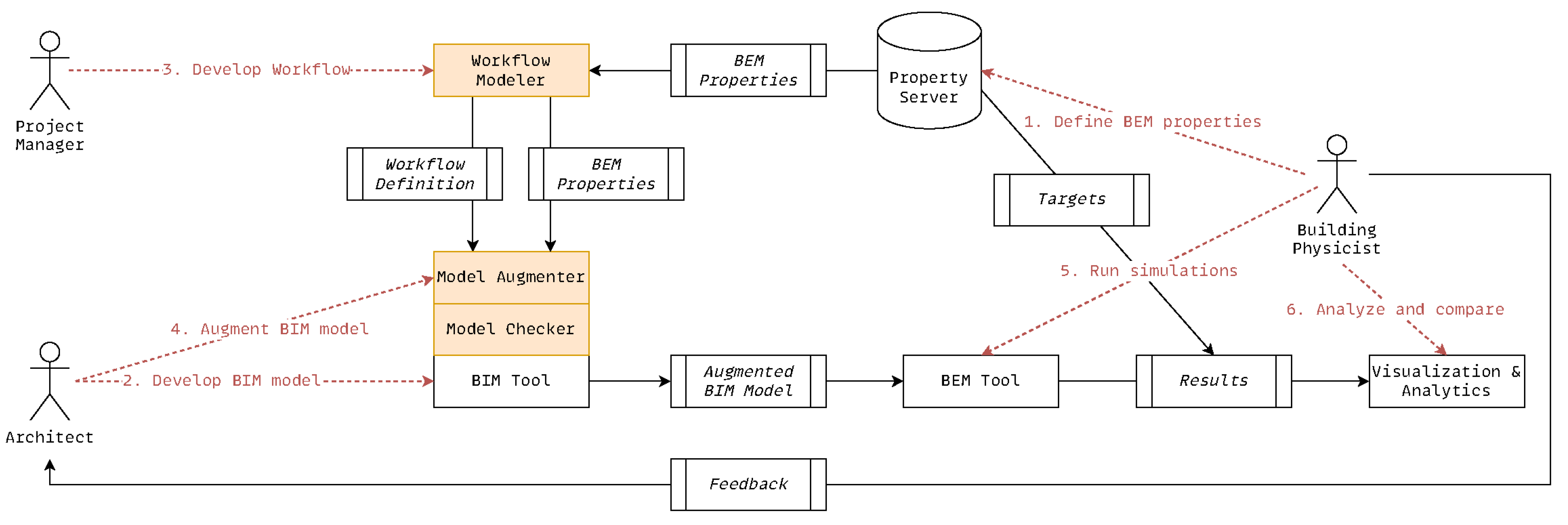
Figure 3 illustrates our comprehensive solution proposal. Key aspects of this process have been previously introduced by Jaeger et al. [72]. As a first step, the required properties for BEM simulations (or also any other type of simulation) are defined on the property server. This task is carried out by building physicists, as they possess the expertise to determine which properties are essential for specific simulation types and tools.
Within the property server, BEM properties are defined along with their relevance to specific simulation tools and types (e.g., energy or lighting). The property server manages associated entities, including property sets and model elements representing construction components such as walls or windows. Each property typically applies to multiple simulation types and tools. While the core semantic definition of a property (e.g., its data type and description) remains consistent, its name and unit may vary depending on the concrete simulation tool. This polymorphic characteristic necessitates a mapping mechanism that links properties to relevant simulation tools. A similar mapping mechanism applies to property sets. Thus, mapping functionalities for model elements are integrated to ensure compatibility with models originating from different BIM tools. Representative examples of this polymorphic behavior are presented in Table 4 and Table 5. These mapping functionalities enable the automated inference of applicable properties, their representations for different simulation tools, and their associated model elements, and deliver the foundational infrastructure for semi-automated model augmentation. Furthermore, given the highly specialized knowledge required to precisely define property values, our solution allows for pre-defining sets of context-specific default values. This enables key BIM stakeholders, such as architects and building physicists, to enhance a BIM model effectively without requiring highly specific domain knowledge. Such default values facilitate meaningful simulations in the early planning stages, when design decisions may not yet be finalized and various assumptions about a building’s future manifestation are still being considered (e.g., material choices).
As a second step, the BIM model is created by the architect. As this generally concerns geometric and visual design aspects of a building, we will not detail this step, as it falls outside the scope of our work.
The third step involves defining the BIM2BEM workflow where project managers configure new BEM workflows for a building. A workflow specifies the BIM authoring tool and its version, along with the simulation tool and its corresponding version. It also incorporates essential metadata, such as the current project phase (e.g., design, construction, operation) and the simulation type (e.g., energy or lighting). This metadata serves as input to a property inference algorithm, which automatically determines the relevant properties from the property server for the given workflow.
The fourth step involves the actual BIM model augmentation and export. The BIM model is augmented by the architect to produce a version suitable for the target simulation tool. This augmentation utilizes the data structures and semantics provided by the property server. A critical component is the integrated model checker [73], which validates that the augmented BIM model meets the requirements for the designated simulation tool. Technically, the augmentation is realized as a plugin integrated with the BIM authoring tool which natively supports IFC format export. This approach offers several advantages, including providing users with a familiar working environment that minimizes the learning curve and increases user acceptance. Moreover, it enables real-time synchronization, allowing BIM model changes to be immediately reflected in the corresponding simulation model. The transformed BIM model is utilized by building physicists to simulate energy consumption using BEM tools (step 5). The resulting simulation data is subsequently exported for further analysis and evaluation (step 6). CSV has been chosen as the export format for the simulation result format due to its versatility.
Step 6 involves analyzing the simulation results using a dedicated component and comparing them against previously defined energy target corridors. These “corridors” (e.g., various low-energy building standards) are also maintained on the property server. The comparative analysis, which is supported by visualizations, enables stakeholders to assess a building’s simulated performance and, particularly during the design phase, implement design modifications that enhance energy efficiency. Furthermore, results from different building variants can be compared to identify the most effective solution in terms of energy performance. Finally, feedback regarding design deficiencies is communicated to the architect to inform design improvements.
It is important to note that Software Engineers (cf. Table 1) are not depicted in Figure 3, as Figure 3 illustrates the solution proposal in action. However, Software Engineers play an important role in implementing and maintaining the underlying tooling infrastructure, including the property server, model augmentation plugins, model checker components, and integrated simulation tools. Their contributions are essential for realizing the technical framework, though they are not directly involved in its operational execution during typical project workflows.
Our proposed solution establishes a foundational infrastructure for a dependable and automated BIM2BEM workflow. By combining a centralized property server, configurable workflows, automated model augmentation, and model validation mechanisms, our solution ensures consistency and interoperability across tools and disciplines. This enables stakeholders to efficiently generate simulation-ready models within familiar BIM environments while supporting traceable, tool-agnostic transformations and integrations. The resulting workflow thereby enhances both the dependability and scalability of BEM along the project life cycle.

5. Artifact Implementation

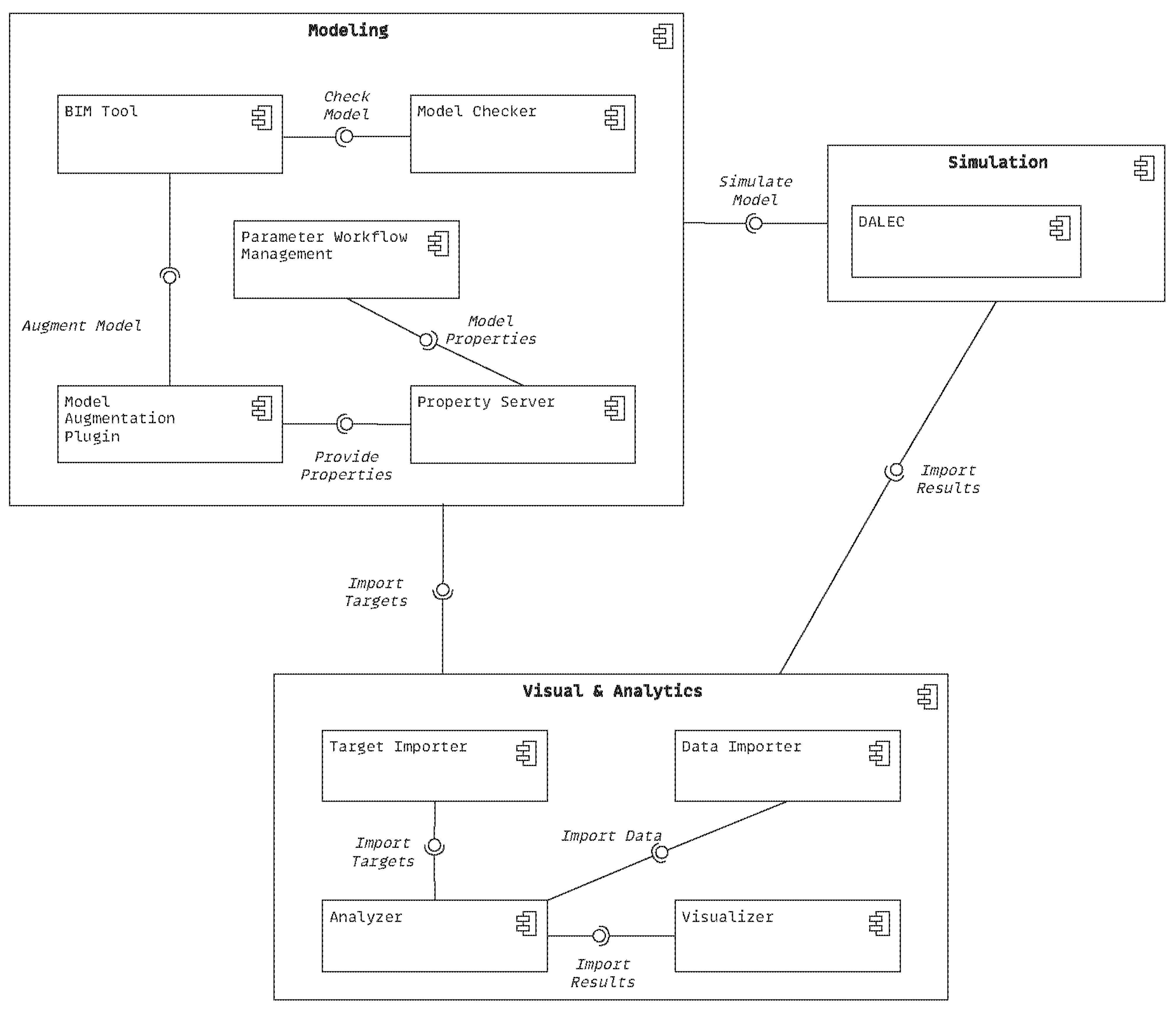
Figure 4 provides a component-based overview of our solution architecture, detailing the Modeling, Simulation, and Visuals & Analytics components. The Modeling component encompasses all artifacts related to the modeling environment (cf. Section 5.1). The Simulation component encapsulates the BEM tool (cf. the used building performance simulator). Finally, the Visuals & Analytics component processes and analyzes simulation results for visualization and analysis to inform decision-making during subsequent design iterations. These components are detailed below in Section 5.1, Section 5.2 and Section 5.3.

5.1. Modeling Environment

The modeling environment of our solution proposal comprises four sub-components, detailed below. The employed BIM Tool, Autodesk Revit (https://www.autodesk.com/products/revit/ (5 April 2026)), a common off-the-shelf architectural design tool, will not be further detailed here.

5.1.1. Property Server

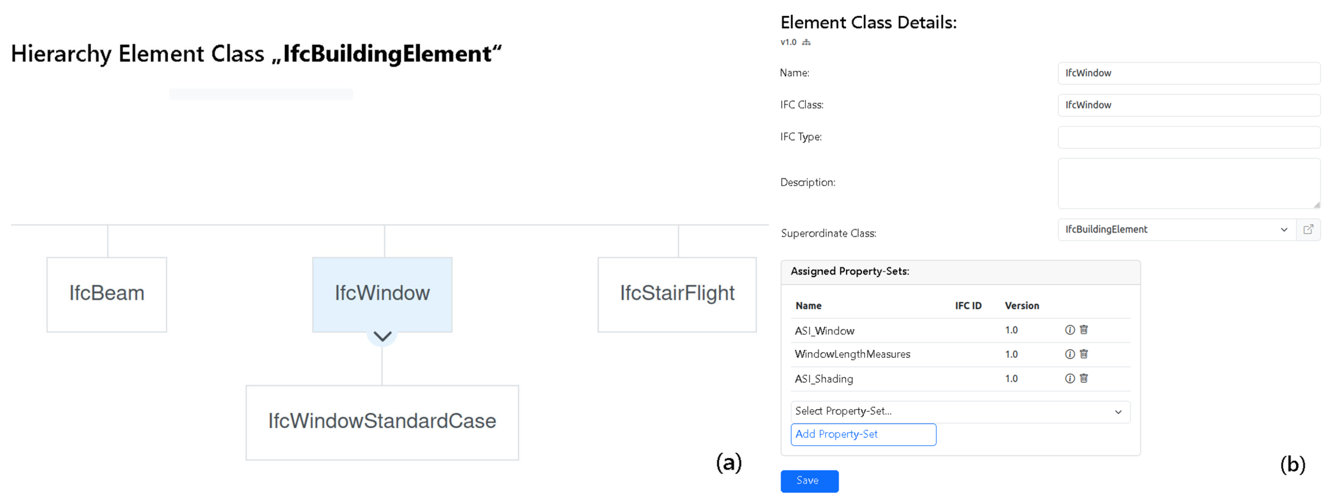
The Property Server is designed as a platform to enhance BIM consistency by standardizing the representation of building component properties according to DIN SPEC 91400 [74] and STLB-Bau [75]. It offers a graphical interface for describing building components with standardized properties (cf. Figure 5), which are bundled in property libraries. This allows users to enrich their BIM models efficiently, thereby optimizing model data management and planning processes. The property server also supports data import (e.g., part and property specifications) via CSV to enable the reuse of existing building component descriptions.
Property libraries are often owned by specific organizations, with viewing and editing rights restricted to particular roles. To ensure consistency over time, a versioning process for property libraries has been implemented. In addition to modeling building parts and their properties, users can also add relevant default values. After importing a property library into a BIM model via the Model Augmentation Plugin (see below), the properties and default values provided by the library become available downstream in the BIM model along the engineering tool chain.
The server is built using a tech stack that comprises a Spring Boot (https://spring.io/projects/spring-boot (5 April 2026)) backend and an Angular (https://angular.dev (5 April 2026)) frontend, and Keycloak (https://www.keycloak.org (5 April 2026)) for Single Sign-On (SSO) authentication and user management.
The content, defined as the specific sets of properties within the property server, is closely aligned with the requirements of the simulation programs. This alignment is primarily informed by the findings of a preceding study, which provides a foundational basis for the properties incorporated into the server [76].

5.1.2. Parameter Workflow Management

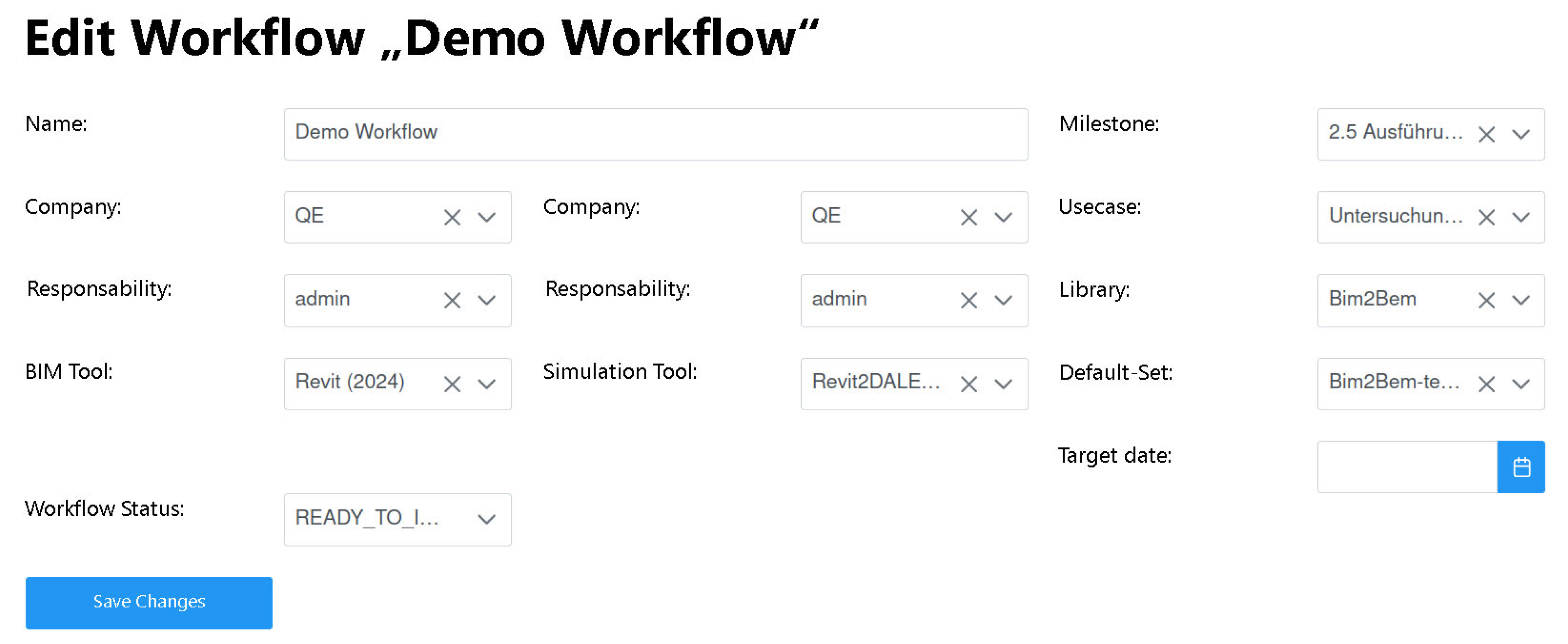
The Parameter Workflow Management (PWM) component offers functionality to create and configure workflows with essential metadata. Figure 6 illustrates a screenshot of the PWM for modeling a workflow (e.g., “Demo Workflow”).
Furthermore, the component is designed to facilitate the sharing of libraries from the server among project partners. In addition, the PWM maintains strict ownership integrity and ensures that each partner can manage and control their respective data without relinquishing ownership rights. To maintain project consistency, the PWM anchors workflows to specific library versions to ensure that a published library version remains unchanged throughout a project’s life cycle. This maintains the integrity and reliability of project data and prevents discrepancies and inconsistencies. Such a systematic approach establishes a stable environment for model and data management across a project’s life cycle.
Similarly to the server, the PWM is constructed using a technology stack that includes a Spring Boot backend and an Angular frontend, and Keycloak for SSO authentication and user management. Observe that at the implementation level, a property (cf. a characteristic of a building element) manifests as a parameter, i.e., a concrete instantiation with an assigned value that is passed between system components. This terminology aligns with both BIM conventions (where “property” dominates) and software engineering practice (where “parameter” denotes values exchanged via API calls and responses).

5.1.3. Model Augmentation Plugin

The Model Augmentation Plugin is embedded into Autodesk Revit as a plugin to enable users to enhance BIM models with project-specific property libraries. The model augmentation plugin performs the actual model transformation that enriches the BIM model into a BEM-ready model with properties imported from the property server via the PWM. The model augmentation plugin also incorporates robust security and access control measures via Keycloak to ensure that only authorized users can perform model augmentations. The entire process is fully automated to maintain model and data integrity and strict access protocols during model augmentation.
The model augmentation plugin is implemented in C# for Autodesk Revit; porting to other BIM authoring tools requires a platform-specific reimplementation while the underlying property server API and transformation logic remain unchanged (cf. Section 7.4). The actual model transformations implement a visitor pattern [77] which iterates over the BIM model and expands model elements as necessary, e.g., extending them with BEM-relevant properties if available from the property server.

5.1.4. Model Checking and IFC Export

Once the model has been augmented and is ready to be exported into IFC using Revit’s built-in IFC exporter, a custom Model Checker [73] ensures that the model fulfills all necessary modeling requirements of the BEM Tool. This includes, e.g., ensuring all building part properties and their value parameterizations are correctly provided. Our model checker, which is specifically developed for IFC-based models [73], allows for specifying both numerical and semantic checking rules to validate model correctness. Listing 1 presents a sample rule used to verify whether an IfcWindow has its Sonnenschutztyp_FA1C1 property (the reduction factor of insulation as to a sun screen) modeled and set.
Listing 1 Example rule whether an IfcWindow has the property Sonnenschutztyp_FA1C1 set.
Energies 19 03565 i001
After successful validation, the model is exported to IFC using Revit’s standard built-in IFC exporter. The model checker blocks the export until all transfer requirements are satisfied to ensure that only validated models proceed to simulation. This guarantees property completeness by design for the target BEM tool.

5.2. Simulation Component

The Simulation component abstracts away the employed simulation environment (i.e., the BEM tool). This is possible by capitalizing on MBTI by ensuring that the model augmentation plugin transforms the BIM model into a BEM-ready model (cf. Figure 6). This BEM-ready model then seamlessly integrates with the BEM tool and eliminates any media breaks (cf. Section 2.4). This application of MBTI allows for the free choice of BEM tool and ensures that the output from one tool (e.g., the BIM tool) is fully understood by the other (e.g., the BEM tool).
Our current solution employs DALEC as the chosen BEM tool [78]. DALEC is a lightweight, dynamic simulation tool designed for early-stage building design to estimate operational energy use and carbon emissions. Unlike traditional tools, such as EnergyPlus (https://energyplus.net (accessed on 5 April 2026)) or IES VE7 (https://www.iesve.com (accessed on 5 April 2026)), DALEC prioritizes speed and ease of use and provides near-instantaneous feedback through simplified dynamics models. It operates primarily on hourly time steps and integrates climate data, occupancy profiles, envelope characteristics, and lighting algorithms to assess heating, cooling, lighting energy, and daylight autonomy. Its main strength derives from real-time support for design iteration, which enables comparative analysis across scenarios. We have integrated DALEC into our workflow without modification and provide it with the IFC model that yields from the BIM tool (cf. Revit), after applying the necessary augmentations and checks, respectively.
Aside from DALEC, we also integrated PHPP (https://passivehouse.com/04_phpp/04_phpp.htm (accessed on 5 April 2026)) successfully as another BEM tool [76] which epitomizes the flexibility and generalizability of our proposal.

5.3. Visuals & Analytics Component

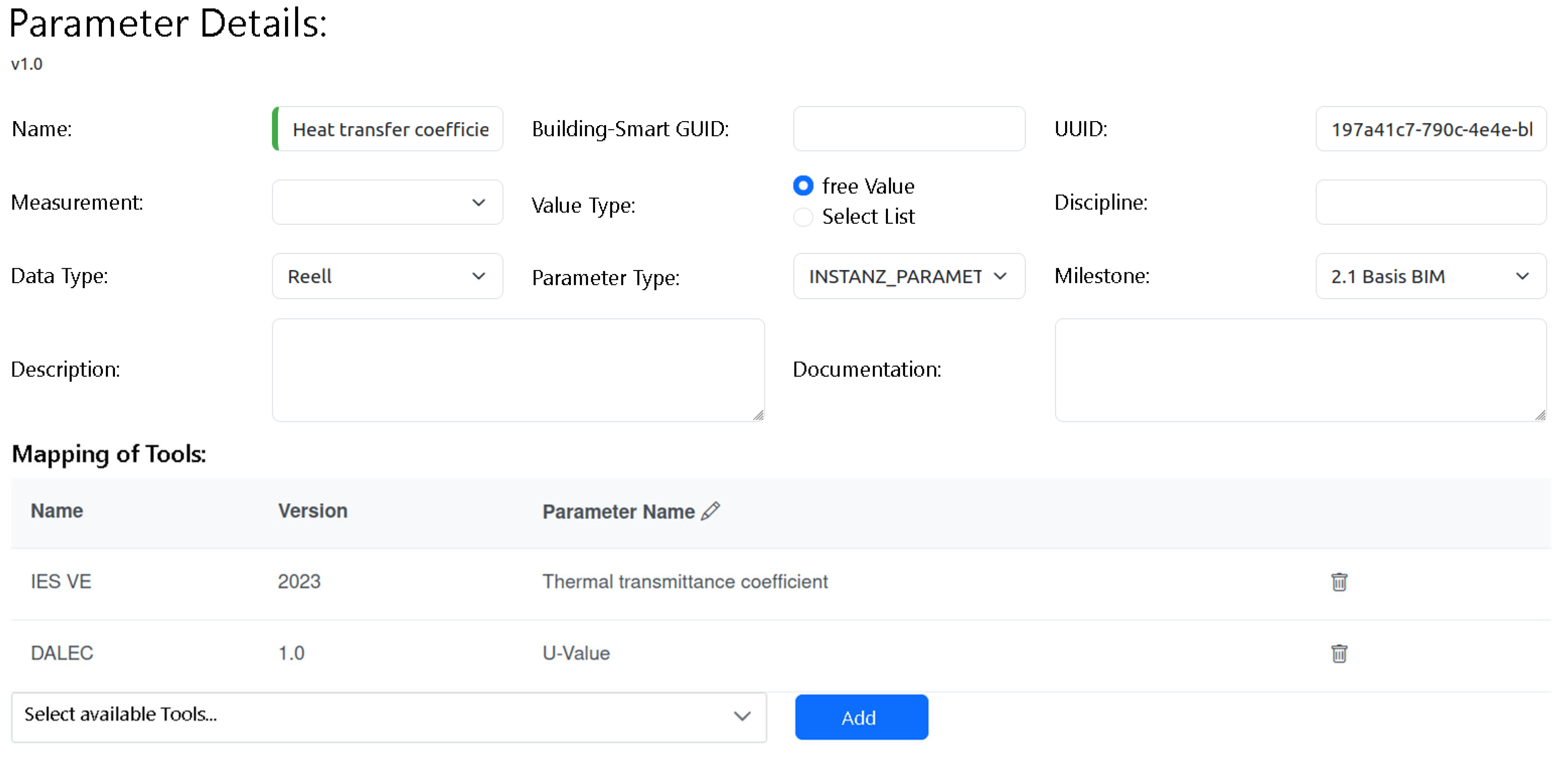
As to the considerable amount of available building performance simulation tools [21], data analysis and visualization pose a considerable challenge by requiring support for this diversity of tools and their often-incompatible output formats. Depending on which BEM tool is employed, specific parameter names might differ (while, e.g., the “Heat Transfer Coefficient” is called “thermal Transmittance Coefficient” in IES VE, DALEC calls it “U-Value”, cf. Table 4 and Figure 7). In addition, though most tools support CSV as a common output format, the internal structure and organization of results inside CSV files is still tool-specific and differs substantially among tools. Yet, our proposed workflow and its tooling infrastructure offer an open path and could easily be adopted in combination with alternative tools. To this end, we once more leverage MBTI (cf. Section 2.2). Specifically, we developed a domain-specific language (DSL) for ad hoc modeling of data import and mapping rules. DSLs are tailored programming or modeling languages designed to express solutions within a particular problem domain, e.g., building simulation performance analysis, with higher abstraction and clarity than general-purpose languages [79].
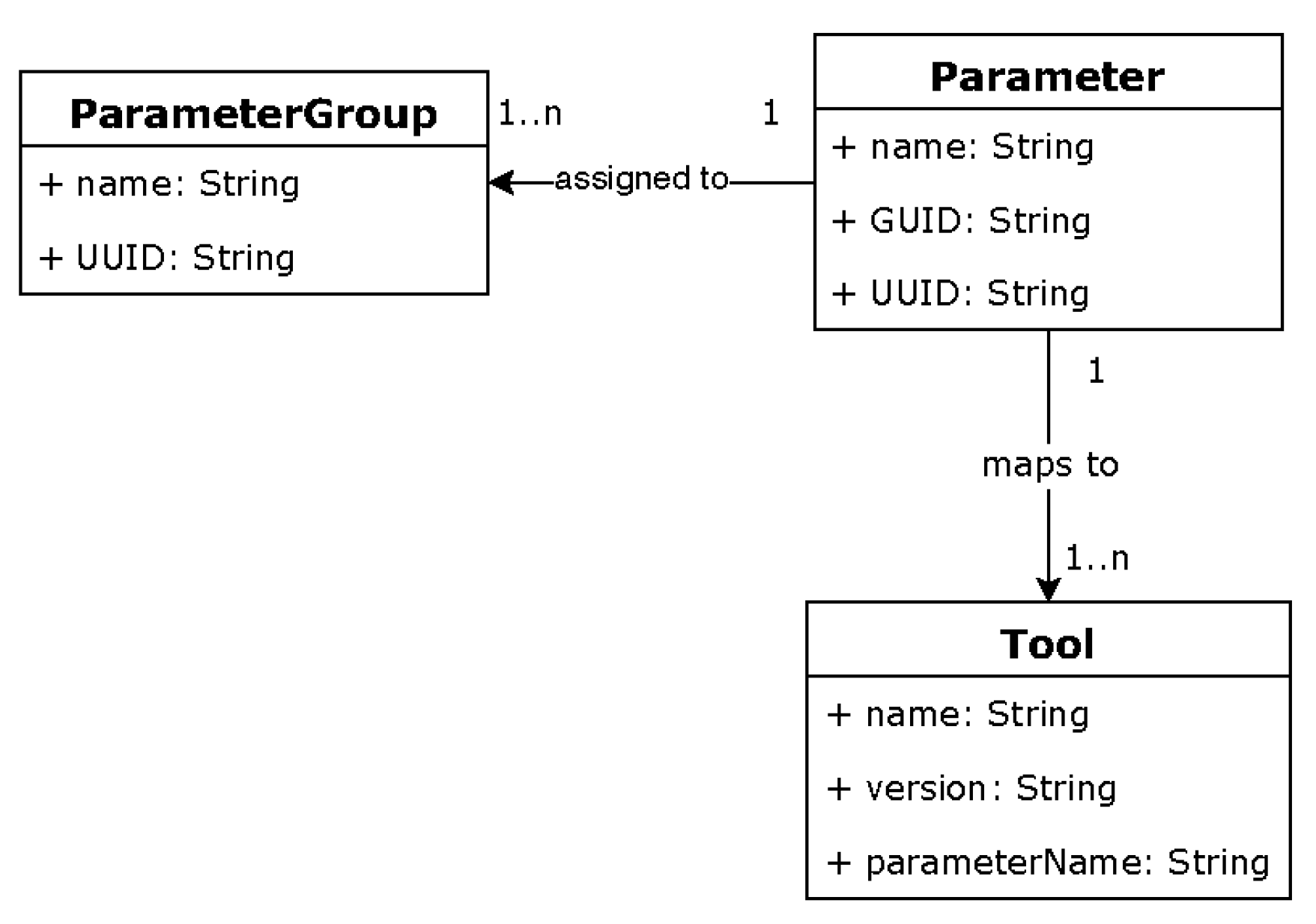
By allowing the definition of tool-independent modeling languages, DSLs can serve as a common lingua franca between tools by enabling, e.g., the definition of transformation rules between tool output and input formats, as done in our case by leveraging a DSL for defining data import and mapping rules. Figure 8 shows the simplified metamodel of our DSL for defining data import and mapping rules.
To provide comparable analyses, our solution maps BEM tool parameters onto their corresponding counterparts as defined in the buildingSMART Data Dictionary [80]. This involves assigning each Parameter a unique bSDD GUID, alongside a name and an internal UUID. Additionally, each Parameter is assigned to at least one ParameterGroup. Both the UUID and the ParameterGroup are derived from the property server as part of the Targets Import from the modeling environment (cf. Figure 4), where targets define the parameters for analysis. A concrete mapping is then defined by associating Parameters to Tools, which requires for each tool its name, version, and the actual tool-specific parameterName. Figure 8 illustrates a screenshot of such a mapping for the “Heat Transfer Coefficient” parameter.
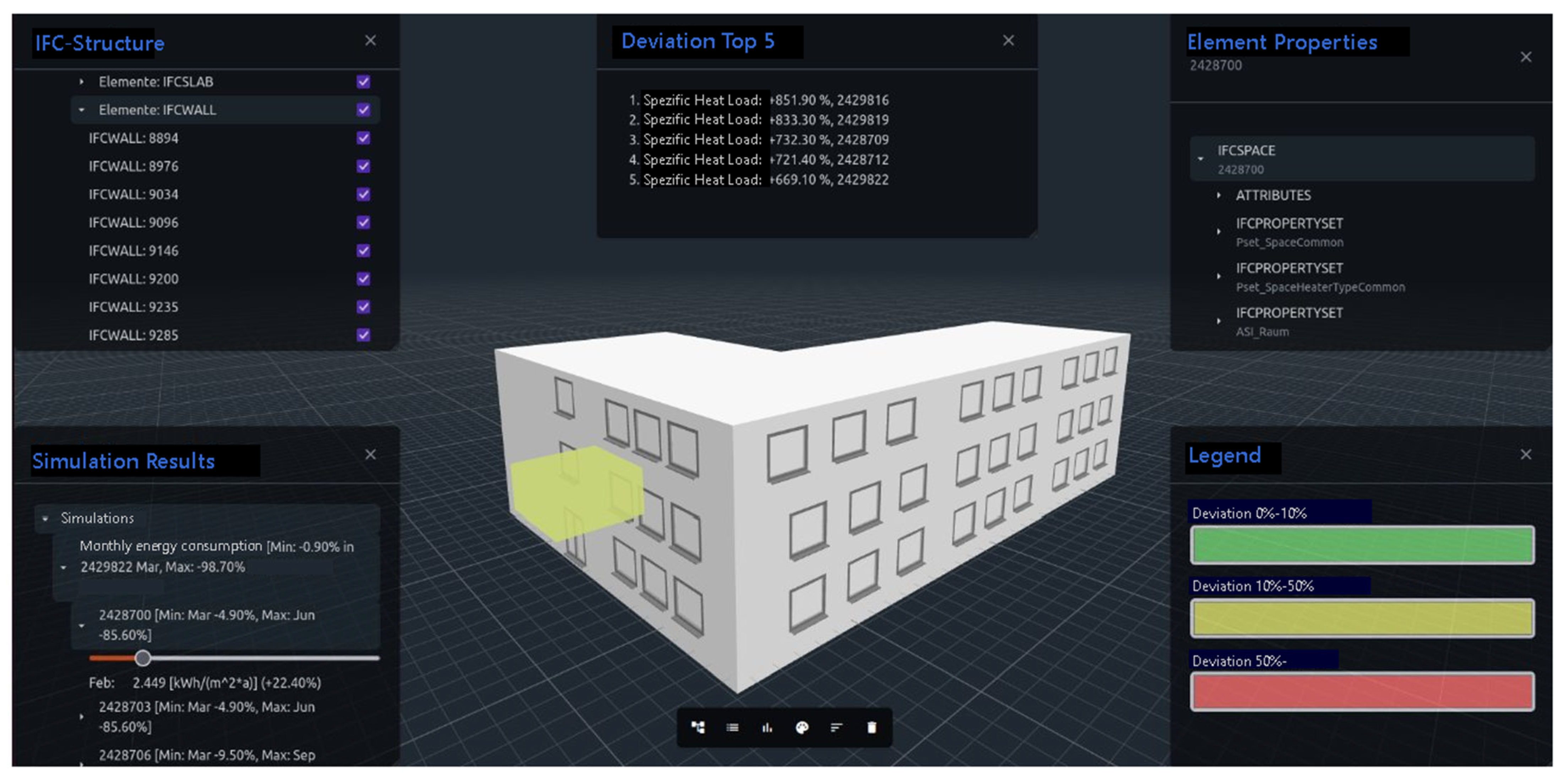
After importing simulation results from a CSV file using the import and mapping rules defined via our DSL, the results can be analyzed for informed decision-making concerning design optimization. Results are then evaluated by comparing them against customizable threshold values (cf. target corridors), which enables a more streamlined assessment process. Our solution provides a simplified table-based overview of results (facilitating comparison across different simulation runs) and a 3D-based visualization of the analyzed building with simulation results augmented in the building model, as shown in Figure 9. This visualization enables detailed inspection of full or building-part-specific performance (e.g., single rooms) over selected time ranges by simultaneously displaying deviations from specified target values (top center in Figure 9).
The visualization is built atop Open BIM Components (https://github.com/ThatOpen/engine_components (accessed on 5 April 2026)) and embedded inside an Angular frontend using Spring-Boot as a backend.

6. Evaluation

Consistent building models are essential for comparable and reliable energy simulations, regardless of the simulation software used. This consistency can only be achieved through reliable and dependable workflows and automated property management, as implemented in our proposed workflow and its tooling. To this end and following the DSR methodology, artifact evaluation must demonstrate that the designed solution (cf. Section 4) addresses the identified problem [62]. For a TRL5 cyber-demonstrator, appropriate evaluation includes technical validation (functional correctness, performance, scalability) and user acceptance assessment with representative stakeholders. However, deployment-level case studies, while valuable, belong to later DSR cycles targeting TRL7+ maturity. Such studies typically focus on comparing simulation tool efficiency, but tools are only as effective as the models they process. Our work addresses this foundational aspect of model quality rather than tool comparison. Our evaluation thus reflects this staging: Section 6.1 presents a benchmarked case analysis of property definition, data filling, and IFC export across Conventional, Shared, and BIM2BEM workflows. Section 6.2 then reports a TAM-based study [22] with 22 construction engineering practitioners. Finally, Section 6.3 reports technical results demonstrating the efficacy of our proposal.

6.1. Stable BIM Exports for Reliable BEM

To demonstrate the reliability and scalability of our proposal in practice, we benchmarked three alternative workflows for property management and IFC export: (i) a conventional manual approach within Revit (“Conventional”), (ii) the use of Revit Shared Parameters (“Shared”), and (iii) our model-driven workflow (“BIM2BEM”). We compare the time needed for property definition, data entry (filling), and IFC export, as shown in Table 6.
The benchmark employs a three-story office building model. The building itself was constructed in reality, and the digital model was created by the University of Innsbruck for the Austrian Skills (https://www.skillsaustria.at/berufe/digitalconstruction (5 April 2026)) competition in preparation for WorldSkills (https://worldskills.org/skills/id/566/ (5 April 2026)). The modeling follows the competition’s practical specifications, Exchange Information Requirements (EIR), and the BIM Execution Plan (BEP), with a level of detail corresponding to construction planning. The building has a net usable area of approximately 600 m2 and a gross volume of approximately 3200 m3, which classifies it as a medium-sized project representative for a majority of projects in the DACH region. The model was structured and designed in accordance with international standards, including the EN ISO 19650 series (https://worldskills.org/skills/id/566/ (5 April 2026)) and EN ISO 7817-1 (https://www.iso.org/standard/82914.html (5 April 2026)). The BEP underlying Austrian Skills complies with current industry practice. Overall, this model can be regarded as a practical, standards-aligned illustration of BIM as used in real-world projects.
We report (i) total process time, (ii) in-Revit working time (susceptible to manual error and media breaks), and (iii) time required per subsequent iteration after initial setup (e.g., re-runs or design iterations in the same organizational environment). The latter excludes one-off setup activities (e.g., creation of a shared parameter file, initial definition/import of parameter libraries/workflows, and creation of custom property set definitions), which usually amortize over multiple projects and iterations. Qualitatively, we reiterate that fully manual parameter creation in Revit is both more error-prone and offers less oversight; BIM2BEM reduces manual work via centralized, versioned libraries, default sets for pre-population, and CSV-based imports. Table 7 summarizes the results. In our model, the scope comprised 82 properties to create and 3033 property assignments to fill across 263 parameterized elements (137 walls, 33 slabs, 2 roofs, 27 rooms, 36 windows, 27 doors, and 1 project information entity).
In summary, BIM2BEM reduces the total process time by ∼33–35% compared to Conventional and Shared, respectively (110 min vs. 163/169 min), and lowers the per-iteration in-Revit time by ∼61% relative to Conventional (163 min vs. 63 min) and by ∼49% relative to Shared (124 min vs. 63 min). These gains grow with model size because one-off setup activities amortize across runs, while manual and error-prone filling in conventional workflows scale with the number of properties. In contrast, BIM2BEM centralizes parameter management in versioned libraries, leverages default sets for bulk pre-population, and supports CSV-based creation/import to curtail repetitive manual work and reduce susceptibility to media breaks. Critically, the approach preserves export reproducibility by construction as all iterations use the same parameter structure, naming conventions, and property sets, which is essential for dependable BIM2BEM handovers in medium-sized, practice-representative projects.
Moreover, the separation between model creation and property management enhances traceability and transparency. Changes in property definitions are made centrally and propagated automatically to all associated projects and stakeholders to guarantee that exported IFC files are always generated according to the latest definitions. This systematic management ensures reproducibility, interoperability, and long-term reliability, which are crucial prerequisites for simulation-based performance analysis in digital building processes.
In summary, BIM2BEM-Flow provides a more efficient and dependable BIM2BEM workflow. It enables stable and repeatable BIM model exports that maintain identical data structures across projects and over time. This is an essential condition for robust BIM2BEM integration, and accurate and dependable BEM simulations.

6.2. Evaluating Tool Use by the Technology Acceptance Model

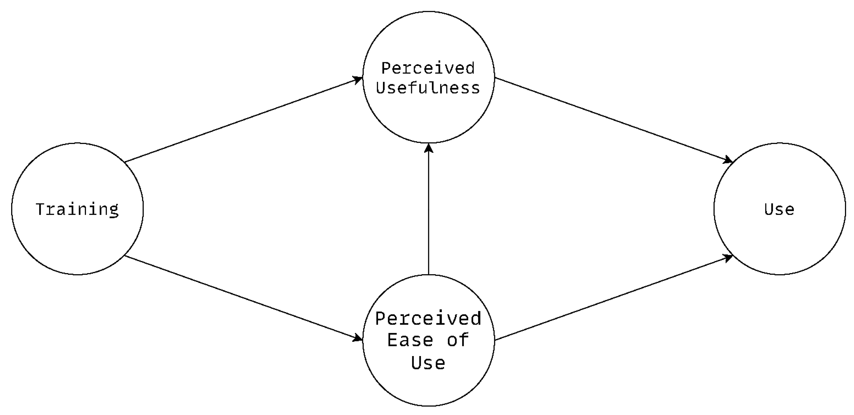
Aside from evaluating dependability aspects of our proposal (cf. Section 6.1), we further evaluated its acceptance and usefulness using the TAM [22]. The TAM is a theoretical framework that explains how users come to accept and use (USE) a technology and is primarily based on two factors: Perceived Usefulness (USF) and Perceived Ease of Use (EOU). The TAM posits that these perceptions influence users’ attitudes toward the technology, which in turn shapes their behavioral intention to use it and ultimately their actual usage behavior. For our study, we have used the adapted TAM from Riemenscheider and Hardgrave [81], which, in addition to Davis’ original proposal, also investigates the influence of prior training (TRA) in using a technology. Figure 10 shows Riemenscheider and Hardgrave’s adapted TAM which comprises the following components:
  • Training (TRA) is an exogenous variable to determine the use of novel technologies and directly influences both USF and EOU. Perceived Ease of Use (EOU) measures the extent to which users believe that using the technology or tool will be effortless and free from difficulties.
  • Perceived Usefulness (USF) assesses users’ beliefs that the technology or tool will enhance their job performance or make their work more effective.
  • Use (USE) represents the overall adoption and use of a technology or tool and is influenced by EOU of use and USF, respectively.

6.2.1. Method

We conducted a user survey following Riemenscheider and Hardgrave [81], which was administered to our sample during a workshop. The sample consisted of 22 stakeholders from construction engineering with academic or industrial backgrounds (16 males and six females). These included academics and researchers (eight), engineers and technicians (four), managers (seven), and specialized BIM roles (e.g., BIM manager or coordinator; three).
The average age of respondents was 38 years, with an average of 6.5 years of experience with BIM (50% of participants were also well acquainted with IFC). The Likert scale used for all survey items (except for USE1) comprised seven points, with ratings ranging from 1 (“strongly disagree”) to 7 (“strongly agree”), and 4 representing “neither agree nor disagree.” For USE1, a four-point scale ranging from 1 (“all the time”) to 4 (“rarely”) was used.
Model Evaluation: We assessed the structural equation model [82] using partial least squares structural equation modeling (PLS-SEM) [83], which was chosen for its advantage in forecasting desired outcomes [84], such as technological acceptance. The statistical computer language R (version 4.5.1) was utilized with the SEMinR package [85] (version 2.3.4) to assess our TAM instance using PLS-SEM [83,85].
Measurement Model Evaluation: We start with the assessment of the reliability and validity of our measurements and investigate (i) the reliability of each indicator by examining their respective loadings, (ii) analyze the internal consistency reliability using composite reliability (ρc), Cronbach’s alpha (ρT), and the reliability coefficient (ρA), (iii) measure the convergent validity based on the average variance extracted (AVE), and (iv) verify the discriminant validity by examining the corresponding Heterotrait–Monotrait (HTMT) ratios [86].
As to (i), all loadings of the four constructs TRA, EOU, USF, and USE are statistically significant at a confidence level of CIα = 0.05 or lower. Additionally, all loadings exceed the threshold value of 0.708 [82], which indicates strong indicator reliability [83].
Regarding (ii), all four constructs exhibit a significant degree of internal consistency [82], with ρc, ρT, and ρA all substantially surpassing 0.70 and mostly exceeding 0.95 [83]. As to (iii), all AVE values substantially exceed the threshold of 0.50 [87], which indicates that the measures of the four constructs TRA, EOU, USF, and USE exhibit a strong degree of convergent validity [83]. Regarding (iv), all ratio values are lower than the liberal cut-off value of 0.9 [87], indicating discriminant validity among the four constructs.
Structural Model Evaluation: We next investigate the structural component of our instance of the TAM. Following Hair and Alamer [87], we (i) examine the structural model collinearity issues based on the variance inflation factor (VIF), (ii) measure the significance and relevance of the structural model relationships (cf. path coefficients) using bootstrapping [88,89,90], and (iii) assess the explanatory capability of the structural model using the coefficient of determination (R2) and effect size (f2).
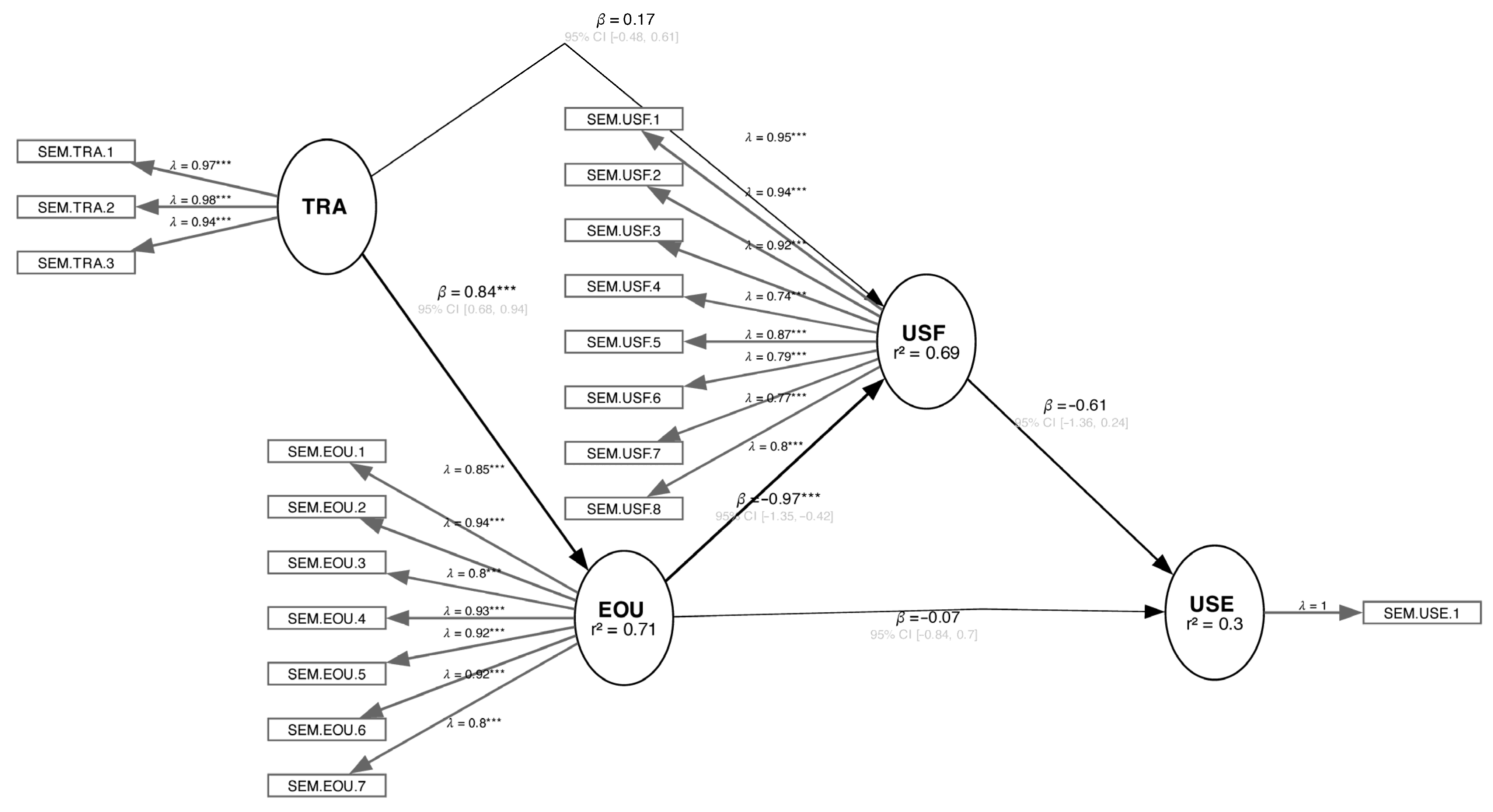
Regarding (i), the VIF analysis reveals that our model does not exhibit any evidence of collinearity among the four constructs [83], as the greatest VIF values are near the ideal threshold of 3 [87,91]. Regarding (ii), the significance and the relevance of the structural model paths is assessed by bootstrapping our model’s sampling distribution [88,89,90] to test the structural model’s relationship coefficients for statistical significance at CIα = 0.05 as summarized in Figure 11. Following Figure 11 and in answering (iii), the R2 values (cf. Figure 11) for the constructs USF and EOU both surpass the critical threshold of 0.75 [83], indicating strong explanatory power, whereas the R2 value of USE (0.3) lacks significant explanatory power. This suggests that our instance of the TAM has a satisfying ability to predict outcomes within the sample [82].

6.2.2. Interpretation

The bootstrapped PLS-SEM (cf. Figure 11; 10,000 iterations) model demonstrates a strong measurement foundation, with all indicator loadings well above the accepted threshold of 0.70 and thus statistically significant. This indicates that the four constructs are reliably measured and reflect their intended dimensions effectively. In particular, the latent constructs for EOU, USF, and TRA are supported by high-quality measurement indicators, which reinforce confidence in the validity of the observed variables.
From a structural perspective, the TAM reveals both strengths and limitations. The path from TRA to EOU is notably strong and significant (β = 0.84, p < 0.001), indicating that EOU plays a critical role in shaping users’ attitudes. Interestingly, TRA has a significant negative effect on USF (β = −0.97, p < 0.001), which suggests that a technology might be used despite having received training. This would reflect willingness to adopt a new technology, even if it requires considerable effort to master, as long as it is beneficial for the task at hand.
However, neither TRA nor USF shows significant influence on USE, and the explained variance for USE remains modest (R2 = 0.30). Collectively, these results suggest that while users may develop strong attitudes based on EOU and USF, these attitudes do not necessarily translate into USE. This points to the potential need for additional predictors, such as behavioral intention or external constraints, to better understand what drives actual use in various settings. Nevertheless, the consistently high evaluations of EOU and USF suggest that participants view our solution positively and would likely engage with it in practical contexts.

6.3. Technical Evaluation

To comprehensively evaluate our solution, we also conducted a series of technical benchmarks. Processes were selected for benchmarking if a significant portion of their functionality involved automation rather than manual work. The following processes were included in the evaluation:
1. Importing properties into a Revit model (Modeling Environment, Model Augmentation Plugin).
2. Exporting properties from a Revit model (Modeling Environment, Model Augmentation Plugin).
3. Model checking of a Revit model (Modeling Environment, Model Checker).
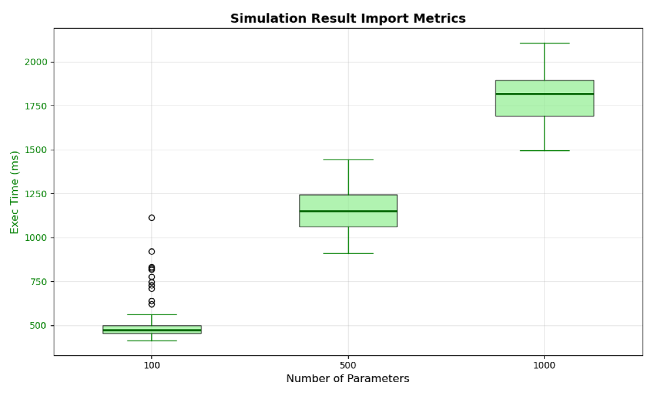
4. Importing simulation results (Visual & Analytics, Data Importer).
The corresponding artifacts for each process are provided in parentheses (cf. Section 5). For processes 1–3, both execution time and peak memory usage delta were recorded. The peak memory usage delta represents the additional memory consumption caused by the plugin compared to Revit’s baseline. To calculate this, a baseline memory peak was recorded prior to executing the benchmarked logic. The reported value is the difference between the peak memory usage during the benchmark and the recorded baseline.
For process 4, only the execution time was recorded, as the actual operation is performed on a server rather than the workstation used for testing. Each process was benchmarked with the following numbers of different BEM-related properties: 100, 500, and 1000. A model with 100 parameters corresponds to a small model, while a model with 1000 properties can be considered a relatively large model. For each process and property count, 100 runs were performed and averaged to minimize the influence of external factors on the performance measurements. All benchmarks ran on a workstation with specifications as shown in Table 8. This categorization is in line with recent research in BIM, where the number of elements or components is commonly used as a proxy for model size and complexity. For example, Ghosh Mondal et al. [92] showed that increasing the number of components in bridge BIM models directly affected computational performance, reflecting a practical relationship between element count and model scale.
The results of the benchmarks are summarized in Table 9 and Table 10.
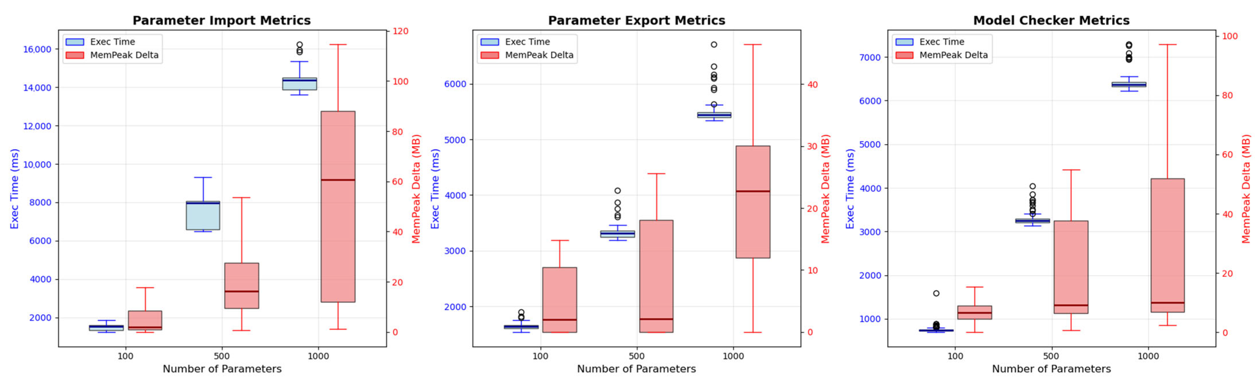
For a linear increase in the number of properties, the expected GF would be 5 when scaling from 100 to 500 properties and 2 when scaling from 500 to 1000 properties. As observed in Table 9 and Table 10, while some processes exhibit GFs slightly exceeding these theoretical values, the deviations are minimal and remain within acceptable bounds. Moreover, in several cases, sublinear growth can be observed. These results suggest that our solution is both performant and scalable, and thus capable of handling increasing model and data sizes without a perceivable loss of efficiency. For a more comprehensive visualization, Figure 12 and Figure 13 present the results as box plots.

7. Results and Discussion

This section synthesizes and interprets the findings from our evaluation and positions them within the broader context of our research objectives and related work. We also examine the broader technical, methodological, and organizational implications of our work and assess threats to validity.

7.1. Answering Our Research Questions

Answers to RQ1: Our evaluation demonstrates that our solution effectively addresses the identified obstacles from Section 2 through three key mechanisms. First, the property server provides centralized, version-controlled management of BEM-specific properties and eliminates inconsistencies that typically arise from decentralized, ad hoc property definitions. Second, automated model augmentation via a dedicated plugin reduces manual effort and human error while ensuring that BIM models consistently incorporate all necessary properties for downstream simulation. Third, the integrated model checker validates semantic correctness before simulation and catches errors early in the workflow. Together, these mechanisms substantially reduce specification uncertainty, one of the primary factors compromising BEM reliability.
Answers to RQ2: Our workflow, established through MBTI, ensures tool continuity by eliminating media breaks at the model level. By leveraging standardized IFC exports that are enriched with BEM-specific properties, our approach enables seamless model and data exchange between BIM and BEM tools without manual intervention. The application of MBTI extends beyond the modeling-to-simulation transition. Our DSL for data import and mapping ensures that simulation results from diverse BEM tools can be consistently analyzed and visualized. This end-to-end integration significantly enhances dependability by reducing information loss, maintaining traceability, and supporting reproducible workflows across project iterations. The TAM-based evaluation (cf. Section 6.2) further confirms satisfying user acceptance, with strong perceived usefulness and ease of use, indicating that our solution is both effective and practically relevant.
Answers to RQ3: Our work applies reliability engineering principles through systematic model validation, automated consistency checks, and version-controlled property management. The model checker embodies formal verification practices by encoding transfer requirements as machine-readable rules (cf. Listing 1) and ensures that only semantically correct models proceed to simulation. This proactive approach to error detection mirrors fault prevention strategies in dependable systems engineering. Furthermore, the property server’s versioning mechanism ensures that property definitions remain stable throughout a project’s life cycle, which supports reproducibility, a key criterion for dependable engineering processes. The technical evaluation (cf. Section 6.3) demonstrates that these dependability enhancements are achieved without significant performance penalties. This combination of formal validation, automation, and traceability establishes a foundation for dependable BEM that extends beyond individual simulations to support continuous improvement throughout the building life cycle.

7.2. Results in the Context of Related Work

Our work extends recent advances in BIM2BEM. While Bastos et al. [3] and Li et al. [4] identified critical barriers such as data inconsistency, lack of standardized protocols, and manual intervention requirements, our solution directly addresses these challenges through a structured, model-driven environment. Ciccozzi et al. [5] noted the absence of fully automated, reliable end-to-end BIM2BEM pipelines. Our solution demonstrates that such automation is achievable through MDE combined with formal model checking and centralized property management.
Comparing our approach to recent related work underscores its contribution. Iliadis et al. [63] focus on semantic enrichment for IFC-to-Modelica integration but do not address BEM property completeness validation or integration with BIM authoring tools. Giannakis et al. [65] propose an automated workflow with machine learning for BIM data enrichment but require training data and do not guarantee BEM property completeness. Geometry-focused approaches [64] address spatial transformations but leave property transfer to manual workflows. Our workflow integrates these concerns: properties are managed centrally, augmented automatically, validated formally, and exported through standard IFC while providing end-to-end traceability that isolated solutions cannot offer. Beyond data quality and transformation, our approach emphasizes user-facing accessibility and long-term maintainability. By integrating directly into familiar BIM authoring environments (e.g., Revit) and providing intuitive workflow configuration interfaces, we lower adoption barriers while maintaining rigorous validation standards. Furthermore, our environment’s extensibility, demonstrated through proof-of-concept integrations with PHPP and SCALE, suggests broader applicability beyond BEM to encompass life cycle assessment and other performance domains.
The buildingSMART technical report on BIM2BEM workflows [58] advocates for modular and flexible approaches that manage complexity through reproducible, automated engineering processes. Our solution aligns closely with this vision by leveraging open standards (IFC, CSV) and establishing a tool environment with a high degree of automation and dependability. In addition, by mapping tool-specific properties to the buildingSMART Data Dictionary [80], we further promote interoperability and long-term semantic consistency. This positions our work as a practical implementation of the strategic roadmap outlined by buildingSMART to advance both research and practice in dependable BEM.
The MDE community has long emphasized the role of automation and formal methods in enhancing system dependability [20,21,42]. Our work demonstrates that these principles translate effectively to the building domain, where interoperability challenges and heterogeneous tool-chains have historically impeded progress. However, unlike traditional MDE applications in software engineering, the building domain requires careful attention to physical semantics, regulatory compliance, and multidisciplinary collaboration. The successful application of MDE and formal validation in this context suggests that construction engineering can benefit substantially from adopting established software engineering practices.

7.3. Implications

Technical Implications: Our solution demonstrates that MDE can be successfully applied to construction engineering workflows and yield measurable improvements in consistency, efficiency, and reliability. The property server’s versioning and mapping capabilities establish a reusable foundation for managing complex, evolving property sets across heterogeneous tools. This has implications beyond BEM, suggesting pathways for integrating other domain-specific analyses (e.g., structural, acoustic, or life cycle assessment) within a unified model-driven framework. The technical benchmarks (cf. Section 6.3) confirm that our approach scales well, which makes it suitable for large-scale, real-world projects. The successful integration of multiple BEM tools (DALEC, PHPP) and extension to life cycle assessment (SCALE) demonstrates the generalizability of our technical architecture and its potential to serve as a platform for broader digital building workflows.
Methodological Implications: Our adoption of MBTI, and DSLs for data mapping provides a methodological template for addressing analogous interoperability challenges in other engineering domains. By formalizing workflows, validation rules, and property definitions, we enable continuous improvement and knowledge reuse across projects. The TAM-based evaluation (cf. Section 6.2) offers a structured approach for assessing user acceptance of novel tools, which is critical for bridging the gap between research prototypes and industrial adoption. Future research can build upon this methodology to investigate behavioral intention and actual usage patterns over extended periods. The combination of quantitative performance benchmarks and qualitative user acceptance studies provides a comprehensive evaluation framework that can be replicated in other design science research contexts. Furthermore, our approach to establishing transfer requirements through formal model checking represents a novel application of verification techniques to BIM2BEM workflows and opens avenues for future research on semantic validation and automated quality assurance in digital construction.
Organizational Implications: For practitioners, our framework reduces the learning curve and effort required to produce BEM-ready BIM models, accelerates design iterations, and supports evidence-based decision-making from early design stages onward. The clear separation between model creation, property management, and workflow configuration (cf. Figure 1) supports collaborative workflows among participating stakeholders without compromising data integrity and consistency. Organizations adopting our approach can expect improved alignment between design intent and simulated performance, reduced rework, and enhanced accountability through traceability and version control. The reduction in modeling-based effort from 11 min to 3 min per iteration (cf. Table 6) translates to substantial time savings over the course of a project, particularly in iterative design processes where multiple simulation runs are required or in the case of variant studies and their evaluation. The property server’s role-based access control and organizational ownership of property libraries support enterprise-wide standardization and enable organizations to build and maintain institutional knowledge while ensuring compliance with internal standards and external regulations. This is particularly relevant for companies that manage multiple concurrent projects or seek to leverage lessons learned across their portfolio.

7.4. Threats to Validity

Internal Validity: Our TAM-based evaluation (cf. Section 6.2) was conducted with a sample of 22 participants during a single workshop. While the sample included diverse roles and experience levels, the relatively small size and cross-sectional design limit our ability to generalize findings regarding long-term usage behavior. The modest R2 value for USE (0.30) suggests that additional factors such as organizational context, project-specific constraints, or individual preferences may influence actual adoption beyond USF and EOU. The strong negative relationship between TRA and USF (β = −0.97, p < 0.001) warrants further investigation, as it may indicate that participants with more training recognized complexities or limitations not apparent to less experienced users. Future longitudinal studies with larger, more diverse samples are needed to strengthen these findings and track actual usage patterns as opposed to intentions.
External Validity: Our implementation focused on specific tools (Revit, DALEC) and standards (IFC), which may limit the generalizability of our results to other BIM authoring or BEM simulation environments. The choice of Revit reflects the project consortium’s (cf. BIM2BEM-Flow) choice and its widespread use in practice [93] rather than a fundamental architectural constraint. Extending our work to other BIM platforms (e.g., ArchiCAD, Allplan) or IFC-native workflows requires reimplementing the model augmentation plugin for the respective BIM platform. The remaining components, viz. the property server, model checker (open source, IFC-based), and BEM tool integrations, are platform-agnostic and reusable without modification. The same integration effort applies to OpenBIM workflows: while IFC serves as the exchange format throughout, BIM platform-side plugins are necessary to enable communication with the property server and in-tool model augmentation.
While proof-of-concept integrations with PHPP and SCALE demonstrate extensibility, comprehensive validation across a broader range of tools is required to fully assess the framework’s robustness. Additionally, our benchmarks (cf. Section 6.3), while averaged over 100 runs, were conducted on a single workstation configuration, and performance characteristics may vary under different hardware, operating systems, or network conditions. Finally, the workshop participants were drawn from a specific geographic and professional context (Austrian construction and research community), which may limit the applicability of findings to other regulatory environments, construction practices, or organizational cultures.
Construct Validity: The benchmarks focus on execution time and memory usage as primary performance metrics. While these are relevant indicators of scalability and efficiency, they do not capture all aspects of dependability, such as fault tolerance, robustness under erroneous input, or long-term maintainability. Similarly, the TAM constructs (EOU, USF) provide insight into user perceptions but do not directly measure the accuracy or reliability of simulation outcomes. The comparison in Table 6 assumes that manual processes and BIM2BEM-Flow produce equivalent outcomes in terms of simulation accuracy, but this equivalence has not been empirically validated through comparison with measured building performance data. Future work should incorporate additional metrics like error rates, simulation accuracy against measured data, maintenance effort over time, and total cost of ownership to provide a more comprehensive assessment of both technical performance and practical value.
Reliability and Measurement: While our model checker ensures that augmented BIM models meet specified transfer requirements, the quality of simulation results ultimately depends on the accuracy of input parameters, assumptions about occupant behavior, weather data quality, and the fidelity of the simulation tool itself. Our framework addresses specification uncertainty by standardizing and validating inputs, but it does not eliminate operational, scenario, or model uncertainties inherent in BEM (cf. Section 2), though simulation calibration from real operational data can improve results [94] (yet, this is outside the scope of our work). The property server’s default values mechanism is designed to facilitate early-stage modeling but may inadvertently encourage reliance on assumptions rather than informed property selection, potentially introducing systematic biases. Practitioners must remain aware of these limitations and interpret simulation results accordingly, and ideally complement them with sensitivity analyses, uncertainty quantification, and real-world validation.
Scope and Boundaries of the Workflow: Our workflow relies on Revit’s standard IFC exporter. The information available during BEM conversion is therefore bound to what this exporter provides. Potential information loss or modeling inaccuracies may arise from aspects outside our scope and control: limitations of the IFC exporter, automatically generated space boundaries that do not correspond to correct energy balance boundaries, thermal bridge representation (linear loss coefficients vs. simplified U-value approaches), or treatment of geometric complexities such as cantilevered elements (e.g., parapets with “cooling fin” effects at edges and corners). These concerns arise in BIM authoring, IFC export capabilities, geometry processing, or simulation modeling decisions but not in property completeness, which our workflow guarantees by design through the integrated model checker.
That said, our workflow focuses on property completeness for BEM export, not on simulation fidelity. Evaluating whether simulation results accurately predict real-world energy consumption requires case-specific reference data (e.g., measured operational performance) and depends on factors outside our scope: geometry quality from the BIM authoring tool, IFC exporter limitations, space boundary correctness, thermal bridge representation, and simulation solver accuracy. Our contribution guarantees that exported models contain all required properties for the target BEM tool, which is validated by the integrated model checker. Downstream simulation accuracy is governed by the BEM tool, input assumptions, and modeling decisions made by the building physicist, and not by the data transfer workflow itself.

8. Conclusions

Our work addresses the critical challenge of enhancing the dependability of BEM through a model-driven environment that systematically resolves interoperability issues, data inconsistencies, and workflow fragmentation in BIM2BEM processes. Current BEM workflows are frequently compromised by media breaks, tool incompatibilities, and inconsistent property management, which leads to simulation results that can deviate from actual performance [51].
Our solution introduces a tool environment that comprises four key components: (i) a centralized property server that standardizes versions of BEM-specific properties, (ii) automated model augmentation that enriches BIM models with simulation-ready properties, (iii) formal model checking that validates semantic correctness, and (iv) a DSL for consistent data import and visualization. By capitalizing on MBTI, we eliminate media disruptions and establish seamless data exchange between BIM and BEM tools.
Our evaluation demonstrates substantial improvements. First, it reduces time spent in BIM authoring tools from 11 min to 3 min per iteration while ensuring reproducible model exports. Technical benchmarks confirm scalability with often sublinear growth. The TAM evaluation with 22 construction engineering stakeholders reveals high perceived usefulness and ease of use, which indicates strong occupant acceptance.
While our evaluation demonstrates technical feasibility and user acceptance at TRL5, longitudinal deployment studies remain necessary to assess workflow effectiveness in production environments. Such studies would involve tracking property completeness rates, error reduction, and time savings across multiple real-world projects—requiring organizational adoption beyond the scope of this research cycle.
However, several limitations warrant consideration in future work. Our evaluation focused on specific tools and a small sample, necessitating broader validation. While we address specification uncertainty, operational and scenario uncertainties persist. The modest R2 = 0.30 for actual usage suggests that additional factors influence adoption. Future work should extend support to additional BIM tools, integrate uncertainty quantification capabilities, develop machine learning approaches for property recommendations, and establish feedback loops with operational data.
The investigation into the use of probabilistic approaches for entering parameter values and defining boundary conditions warrants further exploration. In this context, triangular distributions may be particularly useful due to their straightforward interpretation when assessing magnitudes. We anticipate that employing this method will provide new insights into the prioritization of influencing factors, including user behavior.
An ML recommendation service, for example, could operate within the property server, with the model augmentation plugin consuming recommendations identically to stored properties. The model checker validates recommendations before export, where necessary user corrections are fed back into the property server as training data. Subsequently, the system must be able to autonomously map the properties and their values found within existing building models to those specified by the simulation tools. The property server that has been developed is intended to serve as the foundational framework for this process.
In the authors’ perspective, integrating the developed approach into a digital building twin (dBT) [95] would present considerable benefits and opportunities during the operational phase. To investigate this approach, the initial step could involve documenting the building’s condition, serving as a foundation for validating the simulations. Building on this validation, the results of the simulations should be systematically integrated into the control units of the individual HVAC components. To ultimately realize the full potential of this integration, it is essential to include external climatic information, particularly weather forecasts and climate data. This integration will ensure that the system can respond predictively and timely to relevant environmental influences.
In addition, while our evaluation demonstrates technical feasibility and user acceptance at TRL5, longitudinal deployment studies remain necessary to assess workflow effectiveness in production environments. Such case studies would involve tracking property completeness rates, error reduction, and time savings across multiple real-world projects that require organizational adoption beyond the scope of this DSR cycle.
In summary, this work demonstrates that MDE provides a viable pathway toward dependable BEM by addressing root causes of unreliability through systematic automation, formal validation, and standardized data management. The principles demonstrated here suggest that construction engineering can benefit substantially from adopting proven software engineering methodologies to manage the complexity of digital building processes.

Author Contributions

Conceptualization, G.F. and P.Z.; methodology, G.F., P.Z. and D.P.; validation, G.F., P.Z., D.P., A.J. and R.P.; writing—original draft preparation, G.F., P.Z. and A.J.; writing—review and editing, G.F., P.Z., A.J., D.P., R.P., R.B. and E.G.; supervision, G.F. and P.Z.; project administration, A.J.; funding acquisition, G.F., R.B. and R.P. All authors have read and agreed to the published version of the manuscript.

Funding

This research was funded by the Austrian Research Promotion Agency FFG under FFG funding contract number 4396767.

Data Availability Statement

Data can be provided upon request. The data are not publicly available due to funding contract.

Conflicts of Interest

The authors declare no conflicts of interest. The funders had no role in the design of the study; in the collection, analyses, or interpretation of data; in the writing of the manuscript; or in the decision to publish the results.

References

  1. International Energy Association (IEA). Energy Efficiency 2024; Technical Report; International Energy Association: Paris, France, 2024. [Google Scholar]
  2. Zhao, H.-X.; Magoulès, F. A review on the prediction of building energy consumption. Renew. Sustain. Energy Rev. 2012, 16, 3586–3592. [Google Scholar] [CrossRef]
  3. Bastos Porsani, G.; Del Valle de Lersundi, K.; Sanchez-Ostiz Gutierrez, A.; Fernandez Bandera, C. Interoperability between building information modelling (BIM) and building energy model (BEM). Appl. Sci. 2021, 11, 2167. [Google Scholar] [CrossRef]
  4. Li, H.; Zhang, J.; Xue, X.; Debs, L.; Chang, S.; Qu, M.; Sparkling, A.; Goldwasser, D. Issues in Bi-directional Interoperability between BIM and BEM. In Proceedings of the Construction Research Congress, Arlington, VA, USA, 9–12 March 2022; pp. 1355–1364. [Google Scholar]
  5. Ciccozzi, A.; de Rubeis, T.; Paoletti, D.; Ambrosini, D. BIM to BEM for Building Energy Analysis: A Review of Interoperability Strategies. Energies 2023, 16, 7845. [Google Scholar] [CrossRef]
  6. Ali, D.M.T.E.; Motuzienė, V.; Džiugaitė-Tumėnienė, R. AI-Driven Innovations in Building Energy Management Systems: A Review of Potential Applications and Energy Savings. Energies 2024, 17, 4277. [Google Scholar] [CrossRef]
  7. Hong, T.; Chen, Y.; Luo, X.; Luo, N.; Lee, S.H. Ten questions on urban building energy modeling. Build. Environ. 2020, 168, 106508. [Google Scholar] [CrossRef]
  8. Zech, P.; Jaeger, A.; Froech, G.; Pfluger, R.; Breu, R. Agile, continuous building energy modeling and simulation. Simulation 2025, 101, 241–265. [Google Scholar]
  9. Alzade, A.; Bollez, M.; Aoun, E.; Mounzer, P.; Saelens, D. Implementing Dynamo in IFC2Modelica Framework for Enhanced Parametrization. In Proceedings of the 19th IBPSA Conference, Brisbane, Australia, 24–27 August 2025. [Google Scholar]
  10. Reinhart, C.F.; Davila, C.C. Urban building energy modeling—A review of a nascent field. Build. Environ. 2016, 97, 196–202. [Google Scholar] [CrossRef]
  11. Crawley, D.B.; Hand, J.; Kummert, M.; Griffith, B.T. Contrasting the capabilities of building energy performance simulation programs. Build. Environ. 2008, 43, 661–673. [Google Scholar] [CrossRef]
  12. Hammes, S.; Geisler-Moroder, D.; Weninger, J.; Zech, P.; Pfluger, R. Market demands vs. scientific realities: A comparative analysis in the context of BIM-based and user-centred lighting control. Dev. Built Environ. 2024, 19, 100526. [Google Scholar] [CrossRef]
  13. Manic, M.; Wijayasekara, D.; Amarasinghe, K.; Rodriguez-Andina, J.J. Building energy management systems: The age of intelligent and adaptive buildings. IEEE Ind. Electron. Mag. 2016, 10, 25–39. [Google Scholar] [CrossRef]
  14. Fernald, H.; Hong, S.; Bucking, S.; O’Brien, W. BIM to BEM translation workflows and their challenges: A case study using a detailed BIM model. In Proceedings of the eSim 2018: 10th Conference of IBPSA, Montréal, QC, Canada, 9–10 May 2018. [Google Scholar]
  15. Miller, J.; Jaeger, A.; Froech, G.; Pfluger, R.; Zech, P.; Hauer, M. Combined web-based and BIM tool plugin toolchain to support data exchange during BIM2SIM workflows. In Proceedings of the BauSim Conference 2024: 10th Conference of IBPSA, Vienna, Austria, 23–26 September 2024; pp. 40–46. [Google Scholar]
  16. Agh, H.; Ramsin, R. A Model-Driven Approach for Software Process Line Engineering. Software 2023, 2, 21–70. [Google Scholar] [CrossRef]
  17. Montecchi, L.; Lollini, P.; Bondavalli, A. Dependability Concerns in Model-driven Engineering. In Proceedings of the 2011 14th IEEE International Symposium on Object/Component/Service-Oriented Real-Time Distributed Computing Workshops, Newport Beach, CA, USA, 28–31 March 2011; IEEE: New York, NY, USA, 2011; pp. 254–263. [Google Scholar]
  18. Succar, B.; Sher, W.; Williams, A. Measuring BIM Performance: Five Metrics. Archit. Eng. Des. Manag. 2012, 8, 120–142. [Google Scholar] [CrossRef]
  19. Succar, B. Building Information Modelling Framework: A Research and Delivery Foundation for Industry Stakeholders. Autom. Constr. 2009, 18, 357–375. [Google Scholar] [CrossRef]
  20. Brambilla, M.; Cabot, J.; Wimmer, M. Model-Driven Software Engineering in Practice; Morgan & Claypool Publishers: San Rafael, CA, USA, 2017. [Google Scholar] [CrossRef]
  21. Pan, Y.; Zhu, M.; Lv, Y.; Yang, Y.; Liang, Y.; Yin, R.; Yang, Y.; Jia, X.; Wang, X.; Zeng, F.; et al. Building energy simulation and its application for building performance optimization: A review of methods, tools, and case studies. Adv. Appl. Energy 2023, 10, 10013. [Google Scholar] [CrossRef]
  22. Davis, F.D.; Bagozzi, R.P.; Warshaw, P.R. Technology acceptance model. J. Manag. Sci. 1989, 35, 982–1003. [Google Scholar] [CrossRef]
  23. Miller, J. Projekt 4396767-BIM2BEM-Flow. Available online: https://projekte.ffg.at/projekt/4396767 (accessed on 6 March 2025).
  24. ISO 16739-1:2024; Industry Foundation Classes (IFC) for Data Sharing in the Construction and Facility Management Industries—Part 1: Data Schema. International Organization for Standardization: Geneva, Switzerland, 2018.
  25. Miller, J.; Moser, F.; Stumpf, J.; Pfluger, R. Revit2DALEC: A BIM2BEM Combined Thermal and Day-and artificial Light Simulation Workflow. In Proceedings of the 44th International Conference on Engineering and Product Design Education, London, UK, 8–9 September 2022; pp. 124–130. [Google Scholar]
  26. Whittle, J.; Hutchinson, J.; Rouncefield, M. The state of practice in model-driven engineering. IEEE Softw. 2013, 31, 79–85. [Google Scholar] [CrossRef]
  27. Mohagheghi, P.; Fernandez, M.A.; Martell, J.A.; Fritzsche, M.; Gilani, W. MDE adoption in industry: Challenges and success criteria. In Proceedings of the International Conference on Model Driven Engineering Languages and Systems, Toulouse, France, 28 September–3 October 2008; pp. 54–59. [Google Scholar]
  28. Hutchinson, J.; Whittle, J.; Rouncefield, M.; Kristoffersen, S. Empirical assessment of MDE in industry. In Proceedings of the 33rd International Conference on Software Engineering, Honolulu, HI, USA, 21–28 May 2011; pp. 471–480. [Google Scholar]
  29. France, R.; Rumpe, B. Does model driven engineering tame complexity? Softw. Syst. Model. 2007, 6, 1–2. [Google Scholar] [CrossRef]
  30. Jézéquel, J.-M. Taming uncertainty with MDE: An historical perspective. Softw. Syst. Model. 2024, 24, 615–628. [Google Scholar] [CrossRef]
  31. Gamboa, M.A.; Syriani, E. Using workflows to automate activities in MDE tools. In Proceedings of the International Conference on Model-Driven Engineering and Software Development, Rome, Italy, 19–21 February 2016; pp. 25–45. [Google Scholar]
  32. Zech, P.; Hammes, S.; Goldin, E.; Geisler-Moroder, D.; Breu, R.; Pfluger, R. From BIM to Digital Twin: A transformation process through advanced control modeling and automated commissioning using daylight and artificial lighting as examples. Energy Build. 2025, 329, 115184. [Google Scholar] [CrossRef]
  33. Zech, P.; Goldin, E.; Zallinger, C.; Hammes, S.; Pobitzer, P.; Michael, J.; Breu, R. An Ecosystem of DSMLs for Building Commissioning. In Proceedings of the 28th ACM/IEEE International Conference on Model Driven Engineering Languages and Systems (MODELS), Grand Rapids, MI, USA, 5–10 October 2025; IEEE: New York, NY, USA, 2025; accepted for publication. [Google Scholar]
  34. Kappel, G.; Langer, P.; Retschitzegger, W.; Schwinger, W.; Wimmer, M. Model Transformation By-Example: A Survey of the First Wave; Conceptual Modelling and Its Theoretical Foundations: Essays Dedicated to Bernhard Thalheim on the Occasion of His 60th Birthday; Springer: Berlin/Heidelberg, Germany, 2012; pp. 197–215. [Google Scholar]
  35. Kahani, N.; Bagherzadeh, M.; Cordy, J.R.; Dingel, J.; Varró, D. Survey and classification of model transformation tools. Softw. Syst. Model. 2019, 18, 2361–2397. [Google Scholar]
  36. Kapsammer, E.; Reiter, T.; Schwinger, W. Model-based tool integration-state of the art and future perspectives. In Proceedings of the 3rd International Conference on Cybernetics and Information Technologies, Systems and Applications (CITSA 2006), Orlando, FL, USA, 20–23 July 2006. [Google Scholar]
  37. Boje, C.; Guerriero, A.; Kubicki, S.; Rezgui, Y. Towards a semantic Construction Digital Twin: Directions for future research. Autom. Constr. 2020, 114, 103179. [Google Scholar] [CrossRef]
  38. Fowler, M. Domain-Specific Languages; Pearson Education: London, UK, 2010. [Google Scholar]
  39. Goetz, S.; Fehn, A.; Rohde, F.; Kuehn, T. Model-driven software engineering for construction engineering: Quo vadis? J. Object Technol. 2020, 19, 1–22. [Google Scholar]
  40. Zech, P.; Goldin, E.; Hammes, S.; Geisler-Moroder, D.; Pfluger, R.; Breu, R. Model-based auto-commissioning of building control systems. In Proceedings of the 26th International Conference on Enterprise Information Systems (ICEIS 2024), Angers, France, 28–30 April 2024; pp. 121–128. [Google Scholar]
  41. Zech, P.; Ploerer, D.; Pfluger, R.; Breu, R. Scalable Building Energy Efficiency Balancing. In Proceedings of the 2024 Annual Modeling and Simulation Conference (ANNSIM), Washington, DC, USA, 20–23 May 2024; IEEE: New York, NY, USA, 2024; pp. 1–13. [Google Scholar]
  42. Goulão, M.; Amaral, V.; Mernik, M. Quality in model-driven engineering: A tertiary study. Softw. Qual. J. 2016, 24, 01–633. [Google Scholar] [CrossRef]
  43. Slåtten, V.; Herrmann, P.; Kraemer, F.A. Model-driven engineering of reliable fault-tolerant systems—A state-of-the-art survey. In Advances in Computers; Elsevier: Amsterdam, The Netherlands, 2013; Volume 91, pp. 119–205. [Google Scholar]
  44. Rauzy, A.B. Model-Based Reliability Engineering; Altarica Association: Toulouse, France, 2022. [Google Scholar]
  45. Ren, Y.; Qian, C.; Yang, D.; Feng, Q.; Sun, B.; Wang, Z. Model-Based Reliability Systems Engineering; Springer: Berlin/Heidelberg, Germany, 2024. [Google Scholar]
  46. Hofig, K.; Joanni, A.; Zeller, M.; Montrone, F.; Rothfelder, M.; Amarnath, R.; Munk, P.; Nordmann, A. Model-based reliability and safety: Reducing the complexity of safety analyses using component fault trees. In Proceedings of the 2018 Annual Reliability and Maintainability Symposium (RAMS), Reno, NV, USA, 22–25 January 2018; IEEE: New York, NY, USA, 2018; pp. 1–7. [Google Scholar]
  47. Mashkoor, A.; Egyed, A.; Wille, R.; Stock, S. Model-driven engineering of safety and security software systems: A systematic mapping study and future research directions. J. Softw. Evol. Process 2023, 35, e2457. [Google Scholar]
  48. Bocciarelli, P.; D’Ambrogio, A. A model-driven method for describing and predicting the reliability of composite services. Softw. Syst. Model. 2011, 10, 265–280. [Google Scholar] [CrossRef]
  49. Cortellessa, V.; Di Marco, A.; Inverardi, P. Model-driven approach to reliability analysis of component-based systems. In Proceedings of the 2008 15th IEEE International Conference on Engineering of Computer-Based Systems, Belfast, UK, 31 March–4 April 2008; IEEE: New York, NY, USA, 2008; pp. 289–296. [Google Scholar] [CrossRef]
  50. Ciancone, A.; Drago, M.L.; Filieri, A.; Mirandola, R. The KlaperSuite framework for model-driven reliability analysis of component-based systems. Softw. Syst. Model. 2013, 12, 561–588. [Google Scholar] [CrossRef]
  51. Zech, P.; Hammes, S.; Moroder-Geisler, D.; Hauer, M.; Pfluger, R.; Breu, R. Quantifying the Simulation-Reality-Gap in Building Simulation. In Proceedings of the Building Simulation 2025: 19th Conference of IBPSA, Brisbane, Australia, 24–27 August 2025. [Google Scholar]
  52. Zheng, Z.; Zhou, J.; Jiaqin, Z.; Yang, Y.; Xu, F.; Liu, H. Review of the building energy performance gap from simulation and building lifecycle perspectives: Magnitude, causes and solutions. Dev. Built Environ. 2024, 17, 100345. [Google Scholar] [CrossRef]
  53. Reeves, T.; Olbina, S.; Issa, R. Validation of Building Energy Modeling Tools: Ecotect™, Green Building Studio™ and IES™. In Proceedings of the 2012 Winter Simulation Conference (WSC), Berlin, Germany, 9–12 December 2012; pp. 1–12. [Google Scholar]
  54. Raji, B.; Tenpierik, M.J.; van den Dobbelsteen, A. An Assessment of Energy-Saving Solutions for the Envelope Design of High-Rise Buildings in Temperate Climates: A Case Study in the Netherlands. Energy Build. 2016, 124, 210–221. [Google Scholar] [CrossRef]
  55. Elnabawi, M.H. Building Information Modeling-Based Building Energy Modeling: Investigation of Interoperability and Simulation Results. Front. Built Environ. 2020, 6, 573971. [Google Scholar] [CrossRef]
  56. Maamari, F.; Andersen, M.; de Boer, J.; Carroll, W.L.; Dumortier, D.; Greenup, P. Experimental Validation of Simulation Methods for Bi-Directional Transmission Properties at the Daylighting Performance Level. Energy Build. 2006, 38, 878–889. [Google Scholar] [CrossRef]
  57. Oleiwi, M.Q.; Mohamed, M.F.; Sulaiman, M.K.A.M.; Che-Ani, A.I.; Raman, S.N. Thermal Environment Accuracy Investigation of Integrated Environmental Solutions-Virtual Environment (IES-VE) Software for Double-Story House Simulation in Malaysia. ARPN J. Eng. Appl. Sci. 2019, 14, 3659–3665. [Google Scholar] [CrossRef]
  58. Ouellette, J.W.; Woodard, P.; Bekboliev, M. Information Delivery Manual (IDM) Development for Building Information Modelling (BIM) and Building Energy Modelling (BEM) Workflows; Technical Report BR-2022-1044-TR; BuildingSMART International: Kings Langley, UK, 2022. [Google Scholar]
  59. Chong, A.; Gu, Y.; Jia, H. Calibrating building energy simulation models: A review of the basics to guide future work. Energy Build. 2021, 253, 111533. [Google Scholar] [CrossRef]
  60. Coakley, D.; Raftery, P.; Keane, M. A Review of Methods to Match Building Energy Simulation Models to Measured Data. Renew. Sustain. Energy Rev. 2014, 37, 123–141. [Google Scholar] [CrossRef]
  61. Nazari, M.; Matusiak, B. Daylighting simulation and visualization: Navigating challenges in accuracy and validation. Energy Build. 2024, 312, 114188. [Google Scholar] [CrossRef]
  62. Wieringa, R. Design Science Methodology for Information Systems and Software Engineering; Springer: Berlin/Heidelberg, Germany, 2014. [Google Scholar]
  63. Iliadis, P.; Bellos, E.; Rotas, R.; Kitsopoulou, A.; Ziozas, N.; Nikolopoulos, N.; Kosmatopoulos, E. Comprehensive Framework for Dynamic Energy Assessment of Building Systems Using IFC Graphs and Modelica. J. Build. Perform. Simul. 2025, 18, 478–499. [Google Scholar] [CrossRef]
  64. Pereira, V.; Santos, J.; Leite, F.; Escórcio, P. Using BIM to Improve Building Energy Efficiency–A Scientometric and Systematic Review. Energy Build. 2021, 250, 111292. [Google Scholar] [CrossRef]
  65. Giannakis, G.I.; Katsigarakis, K.I.; Lilis, G.N.; Rovas, D.V. A Workflow for Automated Building Energy Performance Model Generation Using BIM Data. In Proceedings of the Building Simulation 2019: 16th Conference of IBPSA, Rome, Italy, 2–4 September 2019; IBPSA: Wakefield, MA, USA, 2019; Volume 16, pp. 167–174. [Google Scholar]
  66. de Freitas Guilherme, L.; Fernandes Vaz, C.; Soares da Silva, C.; Fernandes Maciel, A.; de Araújo, A. BIM/BES Interoperability: A Case Study Between Revit®, Designbuilder®, IES-VE®, and E-Quest®. Int. J. Prof. Bus. Rev. 2024, 9, 25. [Google Scholar] [CrossRef]
  67. Kamel, E.; Memari, A.M. Review of BIM’s application in energy simulation: Tools, issues, and solutions. Autom. Constr. 2019, 97, 164–180. [Google Scholar] [CrossRef]
  68. Di Biccari, C.; Calcerano, F.; D’Uffizi, F.; Esposito, A.; Campari, M.; Gigliarelli, E. Building information modeling and building performance simulation interoperability: State-of-the-art and trends in current literature. Adv. Eng. Inform. 2022, 54, 101753. [Google Scholar] [CrossRef]
  69. Wang, M.; Lilis, G.; Mavrokapnidis, D.; Katsigarakis, K.; Korolija, I.; Rovas, D. Automated and scalable BIM2BEM framework with zoning-based model simplification leveraging knowledge graph integration. Autom. Constr. 2026, 182, 106712. [Google Scholar] [CrossRef]
  70. Lilis, G.; Wang, M.; Katsigarakis, K.; Mavrokapnidis, D.; Korolija, I.; Dimitrios, R. BIM-based semantic enrichment and knowledge graph generation via geometric relation checking. Autom. Constr. 2025, 173, 106081. [Google Scholar] [CrossRef]
  71. Bass, L.; Clements, P.; Kazman, R. Software Architecture in Practice: Software Architect Practice, 3rd ed.; Addison-Wesley: Boston, MA, USA, 2012. [Google Scholar]
  72. Jaeger, A.; Zech, P.; Miller, J.; Froech, G.; Breu, R. Towards Enabling Continuous Integrated BIM2SIM Workflows with Model Augmentation Strategies. In CEUR Workshop Proceedings; CEUR: Bonn, Germany, 2024; Volume 3855. [Google Scholar]
  73. Zech, P.; Burger, P.; Hammes, S.; Geisler-Moroder, D.; Breu, R. BIMReason: Validating BIM model correctness. Bauphysik 2024, 46, 332–339. [Google Scholar] [CrossRef]
  74. DIN SPEC 91400; Building Information Modeling (BIM)—Classification of Construction Works Part A: Basic Principles and Identification Code for Construction Works. DIN German Institute for Standardization: Berlin, Germany, 2017.
  75. Deutsche Institut für Normung e.V. (DIN). STLB-Bau: Standardisierte Leistungsbeschreibungen fuer den Bau. 2020. Available online: https://www.stlb-bau-online.de/ (accessed on 6 March 2026).
  76. Miller, J.; Schneiderbauer, L.; Hauer, M.; Jaeger, A.; Froech, G.; Pfluger, R.; Moser, S. Enhancing interoperability between building information modeling and building energy modeling: Alphanumerical information exchange for energy optimization in early design stages. Appl. Sci. 2025, 15, 5789. [Google Scholar] [CrossRef]
  77. Felderer, M.; Zech, P.; Fiedler, F.; Chimiak-Opoka, J.; Breu, R. Towards Adaptive Test Code Generation for Service-oriented Systems. In Proceedings of the 2009 Ninth International Conference on Quality Software, Jeju, Republic of Korea, 24–25 August 2009; IEEE: New York, NY, USA, 2009; pp. 155–160, 6 March 2026. [Google Scholar]
  78. Werner, M.; Geisler-Moroder, D.; Junghans, B.; Ebert, O.; Feist, W. DALEC–a novel web tool for integrated day-and artificial light and energy calculation. J. Build. Perform. Simul. 2017, 10, 344–363. [Google Scholar]
  79. Mernik, M.; Heering, J.; Sloane, A.M. When and how to develop domain-specific languages. ACM Comput. Surv. CSUR 2005, 37, 316–344. [Google Scholar] [CrossRef]
  80. BuildingSMART Data Dictionary (bSDD). An Online Service Offering Standardized Data Dictionaries for BIM, Extending IFC Standards. 2025. Available online: https://www.buildingsmart.org/users/services/buildingsmart-data-dictionary/ (accessed on 5 April 2026).
  81. Riemenschneider, C.K.; Hardgrave, B.C. Explaining software development tool use with the technology acceptance model. J. Comput. Inf. Syst. 2001, 41, 1–8. [Google Scholar] [CrossRef]
  82. Hair, J.F., Jr.; Hult, G.T.M.; Ringle, C.M.; Sarstedt, M. A Primer on Partial Least Squares Structural Equation Modeling (PLS-SEM); Sage Publications: Thousand Oaks, CA, USA, 2021. [Google Scholar]
  83. Hair, J.F., Jr.; Hult, G.T.M.; Ringle, C.M.; Sarstedt, M.; Danks, N.P.; Ray, S. Partial Least Squares Structural Equation Modeling (PLS-SEM) Using R: A Workbook; Springer: Berlin/Heidelberg, Germany, 2021. [Google Scholar]
  84. Latan, H.; Noonan, R.; Matthews, L. Partial Least Squares Path Modeling: Basic Concepts, Methodological Issues and Applications; Springer: Berlin/Heidelberg, Germany, 2017. [Google Scholar]
  85. Ray, S.; Danks, N.; Calero Valdez, A. SEMinR: Domain-specific language for building, estimating, and visualizing structural equation models in R, Estimating, and Visualizing Structural Equation Models in R. SSRN Electron. J. 2021. [Google Scholar] [CrossRef]
  86. Hair, J.F., Jr.; Sarstedt, M. Factors versus composites: Guidelines for choosing the right structural equation modeling method. Proj. Manag. J. 2019, 50, 619–624. [Google Scholar] [CrossRef]
  87. Hair, J.; Alamer, A. Partial least squares structural equation modeling (PLS-SEM) in second language and education research: Guidelines using an applied example. Res. Methods Appl. Linguist. 2022, 1, 100027. [Google Scholar] [CrossRef]
  88. Preacher, K.J.; Hayes, A.F. Asymptotic and resampling strategies for assessing and comparing indirect effects in multiple mediator models. Behav. Res. Methods 2008, 40, 879–891. [Google Scholar] [CrossRef] [PubMed]
  89. Zhao, X.; Lynch, J.G., Jr.; Chen, Q. Reconsidering Baron and Kenny: Myths and truths about mediation analysis. J. Consum. Res. 2010, 37, 197–206. [Google Scholar] [CrossRef]
  90. Nitzl, C.; Roldan, J.L.; Cepeda, G. Mediation analysis in partial least squares path modeling: Helping researchers discuss more sophisticated models. Ind. Manag. Data Syst. 2016, 116, 1849–1864. [Google Scholar] [CrossRef]
  91. Hair, J.F.; Ringle, C.M.; Gudergan, S.P.; Fischer, A.; Nitzl, C.; Menictas, C. Partial least squares structural equation modeling based discrete choice modeling: An illustration in modeling retailer choice. Bus. Res. 2019, 12, 115–142. [Google Scholar]
  92. Ghosh Mondal, T.; Shi, Z.; Zhang, H.; Chen, G. Class-Wise Histogram Matching-Based Domain Adaptation in Deep Learning-Based Bridge Element Segmentation. J. Civ. Struct. Health Monit. 2025, 15, 1973–1989. [Google Scholar] [CrossRef]
  93. Strohm, J. Branchen-Bestandsaufnahme zu BIM in der Tages und Kunstlichtplanung (Stand 06/07 2024); Zenodo: Geneva, Switzerland, 2025. [Google Scholar] [CrossRef]
  94. Chong, A.; Yan, D.; Sun, K.; Zhan, S.; Cheng, S.; Wu, Y.; Chen, Y.; Hong, T. Ten Questions Concerning Calibrating Building Energy Simulation Models. Build. Environ. 2025, 284, 113404. [Google Scholar] [CrossRef]
  95. EN 18162:2026; Building Information Modelling (BIM)—Digital twins applied to the built environment—Concept and definitions. European Committee for Standardization: Brussels, Belgium, 2026.
Figure 1. Conceptual workflow of the BIM2BEM-Flow illustrating the five-step integration process of BIM and BEM. This model-driven workflow supports continuous, interoperable, and reliable energy simulations across all phases of a building’s life cycle, leveraging open standards such as IFC and role-specific tool support.
Energies 19 03565 g001
Figure 2. Conceptual idea of MBTI [36]. Using model transformations, a model from tool A is converted into a model processable by tool B where the transformation is guided by mapping rules among the two metamodels used by tool A and B, respectively. Metamodels must conform to the same meta-metamodel as indicated by the Meta-Object Facility (MOF).
Energies 19 03565 g002
Figure 3. Model-driven workflow of the BIM2BEM-Flow framework. The process spans six coordinated steps, starting with the definition of simulation-relevant properties, followed by BIM model creation, workflow configuration, model augmentation and validation, simulation execution, and result analysis. Each role—Architect, Building Physicist, and Project Manager—interacts with the system through domain-specific components. The framework supports real-time model synchronization, open data standards (IFC), and automatic transformation between BIM and BEM formats to ensure reliable, repeatable, and tool-agnostic energy simulations.
Energies 19 03565 g003
Figure 4. Component-connector diagram of our solution architecture. The Modeling component delivers the modeling environment; the Simulation component encapsulates the BEM tool; finally, the Visuals & Analytics component provides data analytics and visualization facilities for informed decision-making.
Energies 19 03565 g004
Figure 5. Screenshots from the part and property modeling editors of the property server. Left: (a) Hierarchical part modeling of an IfcWindow element and its subtypes. Right: (b) Configured/configurable properties for an IfcWindow element.
Energies 19 03565 g005
Figure 6. Sample workflow configuration with owner information (“QE”), library (“Bim2Bem”), use case (“Untersuchung Energieverbrauch”), project phase (“2.5. Ausfuehrung”), default values (“Bim2Bem-test-values”), and BIM and BEM tools specified (“Revit” and “Dalec”, respectively).
Energies 19 03565 g006
Figure 7. Example parameter import and mapping rule for “Heat Transfer Coefficient” for DALEC and IES VE.
Energies 19 03565 g007
Figure 8. Simplified metamodel of our DSL for defining data import and mapping rules.
Energies 19 03565 g008
Figure 9. Results visualization as provided by our Visuals & Analytics component.
Energies 19 03565 g009
Figure 10. Modified TAM after Riemenschneider and Hardgrave with TRA as an additional variable [81].
Energies 19 03565 g010
Figure 11. Bootstrapped PLS model. Values in ovals denote the R2 value of the respective construct, while value pairs in brackets indicate the 95% confidence interval of the corresponding significant path. Asterisks *** indicate statistical significance at the 0.01 levels.
Energies 19 03565 g011
Figure 12. Box plots representing performance metrics for parameter import, export and model checking.
Energies 19 03565 g012
Figure 13. Box plots representing performance metrics for simulation result import.
Energies 19 03565 g013
Table 1. User groups in the BIM2BEM-Flow framework.
User GroupDescription
ArchitectResponsible for modeling the building from a design point of view and populating the BEM properties necessary for simulation to the best of their knowledge by making use of default values where their knowledge is not sufficient.
Building PhysicistResponsible for defining what data is necessary for which simulation as well as providing sensible default values.
Project ManagerCoordinates workshops and meetings to gather feedback and insights from stakeholders, ensuring all perspectives are considered in the planning process. In addition, they determine which tools are used.
Software DeveloperResponsible for modeling the building from a design point of view and populating the BEM properties necessary for simulation to the best of their knowledge by making use of default values where their knowledge is not sufficient.
Table 2. Scenarios in BIM2BEM-Flow.
IDScenario
SC1Workflow Configuration
Actor: Project Manager. Stimulus: The project manager needs to configure a new energy assessment workflow for a building project. Artifact: BIM2BEM-Flow configuration interface. Response: The project manager accesses the configuration interface and configures a workflow with essential metadata. The system dynamically generates the workflow and infers the necessary steps for successful setup.
SC2Model Transformation
Actor: Project Manager. Stimulus: The project manager requires the transformation of a BIM model for energy analysis. Artifact: The model transformation module of the BIM2BEM-Flow environment. Response: The architect triggers model conversion and the system automatically transforms the model into the proper format for the BEM tool. The architect receives a confirmation of successful transformation.
SC3Integrating New BEM Tools
Actor: Software developer. Stimulus: A new BEM tool needs to be integrated into the BIM2BEM-Flow framework. Artifact: The BIM2BEM-Flow integration module. Response: The developer follows integration guidelines provided by the framework and incorporates the new tool, which is now available for use in BEM simulations.
SC4Evaluating Energy Simulation Results
Actor: Building physicist. Stimulus: The building physicist receives BEM simulation results from the BEM tool and needs to assess their validity. Artifact: Result evaluation interface within the BIM2BEM-Flow environment. Response: The analyst imports and reviews the results in the interface, compares them with preset benchmarks, and determines if the simulations (and the building’s design, respectively) meet the expected operational requirements.
SC5Populating BIM Model with Default Values
Actor: Architect. Stimulus: The architect prepares the BIM model for BEM simulations and provides default values or assumptions for certain properties that are not explicitly modeled or known at the early design stage. Artifact: BIM model within the BIM2BEM-Flow environment. Response: The architect utilizes the BIM2BEM-Flow environment to assign default values to relevant BIM elements from the property server.
Table 3. Functional (FRX) and non-functional (NFRX) requirements for BIM2BEM-Flow.
Functional Requirements
FR1Model and Data InteroperabilityThe solution supports the exchange of data between BIM tools (e.g., Revit) and BEM tools (e.g., DALEC) for energy analysis. The solution utilizes the IFC standard for model and data exchange.
FR2Configuration of WorkflowsUsers configure energy assessment workflows through a user-friendly interface. The solution allows the dynamic generation of tool workflows based on defined exchange requirements.
FR3Automated Transformation of DataThe solution provides automated mechanisms for transforming BIM models into suitable formats for BEM tools. The solution ensures the consistency and accuracy of models and data during transformation processes.
FR4Continuous Parameter ManagementThe solution allows continuous selection, aggregation, and versioning of parameters throughout the project life cycle. Users monitor and adjust energy efficiency parameters dynamically.
FR5User Involvement and CollaborationThe solution facilitates collaboration among stakeholders. The solution supports structured scenario definitions involving various project stakeholders.
Non-Functional Requirements
NFR1UsabilityThe solution is intuitive and easy to navigate, allowing users with varying levels of technical expertise to operate effectively. The solution provides user documentation and help resources.
NFR2PerformanceThe solution executes model augmentation and transformations and import of simulation results within reasonable durations. It handles large models and parameter sets without significant performance degradation.
NFR3ReliabilityThe solution ensures accurate and consistent results in model and data exchanges by embodying the principles of dependability (reliability, accuracy, and validity).
NFR4ScalabilityThe solution scales to accommodate an increasing number of users and tools. It is adaptable to various project sizes and complexities.
NFR5IntegrationThe solution must integrate seamlessly with existing tools used in the construction and real estate industries. It allows for easy updates and compatibility with future tools and standards.
NFR6SecurityThe solution implements measures to secure sensitive project data against unauthorized access. It must ensure that model and data management comply with data protection regulations.
Table 4. Example for general property and property set definitions, relevant for different kinds of BEM tools [72].
EntityNameRelevant SimulationName DALECName IES VE
PropertyHeat transfer coefficientComfortU-ValueThermal transmittance coefficient
PropertyIlluminanceLightIllu_Close/FarRadianceIES_Illuminance
Property setPset_RoomAnyASI_RoomIESVE_Room
Property setPset_WindowAnyASI_WindowIESVE_Glazing
Table 5. Examples for general construction components, their equivalent in the IFC, as well as different BIM authoring tools [72].
Construction ComponentIFCRevit’24Allplan’20
WallIfcWallWallsWall
SpaceIfcSpaceRoomsRoom
RoofIfcRoofRoofsRoof
Table 6. Time comparison for parameter management and IFC export (10 instance properties, 10 elements). Times are approximate and in minutes.
ApproachTotalIn RevitOutsideReuse
Project parameters11110N/A
Shared parameters12N/AN/A9
BIM2BEM-Flow9363
Note: N/A = not available. Project parameters: all time is in Revit. Shared parameters: most work is in Revit. BIM2BEM total includes external workflow creation/import; with reuse, only 3 min in Revit remain.
Table 7. Time comparison (minutes) for property management and IFC export. Model scope: 82 parameters created; 3033 parameter fills across 263 elements. “Setup (out.)” are one-off tasks outside Revit; “Iter.” is per subsequent iteration (excludes one-off setup).
ApproachSetup (out.)In-RevitTotalIter.
Conventional Shared0
19
163
150
163
169
163
124
BIM2BEM476311063
Table 8. System specifications of the workstation used for benchmarking.
ComponentSpecification
CPUAMD Ryzen 7 PRO 5850U with Radeon Graphics,
1901 MHz, 8 Cores, 16 Logical Processors
RAMDDR4, 16 GB
OSWindows 11 Enterprise N, 24H2
Table 9. Performance metrics for parameter import and export. The expected growth factor (GF): 5 when scaling from 100 to 500 properties, 2 when scaling from 500 to 1000. Execution time for parameter import scales almost linearly, while significant sublinear growth can be seen for parameter export. Memory consumption grows sublinearly from 100 to 500 parameters but is seen to be slightly above linear growth from 500 to 1000 parameters.
Process Metric
Statistic Number of Properties
Parameter ImportParameter Export
Execution MeanTime (ms) GFMemory MeanPeak Delta (MB) GFExecution MeanTime (ms) GFMemory MeanPeak Delta (MB) GF
1001474.32-4.66-1637.96-4.91-
5007427.615.03820.294.3563328.682.0328.631.758
100014,263.601.9253.462.6355491.781.6520.822.412
Table 10. Performance metrics for model checking and import of simulation results. The expected growth factor (GF): 5 when scaling from 100 to 500 properties, 2 when scaling from 500 to 1000. Execution time for model checking scales slightly below linear, while the result import shows a significant sublinear growth. Memory consumption for model checking too shows a significant sublinear growth.
ProcessModel CheckerResult Import
MetricExecution Time (ms)Memory Peak Delta (MB)Execution Time (ms)
Statistic Number of
Properties
MeanGFMeanGFMeanGF
100752.57-6.74-509.08-
5003284.554.36419.982.9641163.102.285
10006426.451.95729.461.4741802.231.55
Disclaimer/Publisher’s Note: The statements, opinions and data contained in all publications are solely those of the individual author(s) and contributor(s) and not of MDPI and/or the editor(s). MDPI and/or the editor(s) disclaim responsibility for any injury to people or property resulting from any ideas, methods, instructions or products referred to in the content.