Article

Research on the Performance and Multi-Field Coupling Regulation Mechanism of the Nozzle-Adjustable Steam Ejector


1
Zhan Tianyou College, Dalian Jiaotong University, Dalian 116028, China
2
School of Energy and Power Engineering, Dalian University of Technology, Dalian 116024, China
*
Authors to whom correspondence should be addressed.
Energies 2026, 19(13), 3186; https://doi.org/10.3390/en19133186
Submission received: 6 March 2026 / Revised: 25 May 2026 / Accepted: 2 July 2026 / Published: 4 July 2026

Abstract

Adjustable steam ejectors exhibit significant adaptability to various operating conditions. However, the coupling regulation mechanism between ejector performance and the internal flow field remains insufficiently understood, thereby limiting further optimization. The novelty of this study lies in elucidating the ejector’s performance regulation mechanism by examining the influence of spindle position on non-equilibrium condensation in wet steam. This approach clarifies the flow–thermal–phase-change coupling mechanism and interprets the resulting condensation suppression and shock wave dynamics. In this study, the effects of operating conditions and spindle position on ejector performance were quantitatively characterized. The flow-field evolution was further analyzed through key flow-field variables (pressure, Mach number, temperature, and condensate mass fraction). Moreover, the relationship between ejector performance and flow characteristics was investigated. The flow–thermal–phase-change coupling analysis reveals that the spindle effectively regulates steam ejector performance, internal thermodynamic behavior, and phase-transition processes by adjusting the equivalent throat diameter. Under a representative operating condition, compared with the baseline position (dt = 5.66 mm), moving the spindle in the positive x-axis direction (to dt = 5 mm) decreased the equivalent throat diameter and the motive-fluid mass flow rate by 11.7% and 22.6%, respectively. Consequently, the distance between adjacent shock waves gradually decreased along the flow direction (by approximately 14.1%), and the global maximum Mach number decreased sharply from 2.0 to 1.6 (a 20% reduction). The jet core was significantly shortened, while both the intensity and number of shock waves in the diffuser were reduced. Additionally, the local backflow near the wall of the mixing chamber’s contraction section was suppressed, resulting in a weaker temperature rise in the backflow region. The fluid temperature approached the outlet temperature more gradually, while the average flow-field temperature increased. Meanwhile, the condensate mass fraction in the mixing chamber was significantly reduced (from 0.1 to 0), and the entrainment ratio was enhanced. This configuration is suitable for applications requiring low discharge pressure, high motive pressure, or high suction pressure. Conversely, moving the spindle in the negative x-axis direction enlarged the equivalent throat diameter, which generated higher Mach numbers and stronger shock waves. This enlarged throat configuration enhances the ejector’s resistance to elevated discharge pressure and increases the critical discharge pressure, making it more suitable for high discharge pressure, low motive pressure, or low suction pressure conditions.

1. Introduction

Steam ejectors utilize the expansion of high-pressure steam to entrain and compress low-pressure steam, thereby achieving fluid mixing and energy recovery without additional mechanical or electrical energy consumption. Consequently, they have been widely applied in industrial refrigeration [1], seawater desalination [2], aerospace [3], rail transportation [4], and many other industrial fields [5]. However, the optimal geometric parameters of steam ejectors vary with operating conditions, and conventional fixed ejectors achieve maximum performance only under their design conditions. Accordingly, they experience a sharp decline in performance or even encounter system failure under variable operating conditions.
To improve the adaptability of ejectors and maintain optimal performance under variable operating conditions, various types of adjustable ejectors have been developed. The main adjustable configurations include nozzle-adjustable ejectors [6], ejectors with variable mixing chamber lengths [7], ejectors with cooperative adjustment of the nozzle and mixing chamber [8], and cooperative adjustment ejectors with nozzle outlet position and area ratio [9]. These designs share the objective of modifying crucial performance-related parameters, enabling the mass flow rate and entrainment ratio (Er) to adapt to variable operating conditions, thereby regulating the critical operating range [10]. Among these ejectors, the nozzle-adjustable type is the most widely utilized. The operating principle involves integrating a spindle axially within the nozzle to vary the throat area through spindle movement. Consequently, this movement adjusts the cross-sectional area ratio (AR), which is defined as the ratio of the constant-area mixing chamber area to the nozzle throat area and serves as the key parameter affecting ejector performance. Such ejectors not only adapt the critical operating range to variable operating conditions but also improve the overall system performance [10].
Performance-oriented research on nozzle-adjustable ejectors has mainly focused on adjustable component designs and regulation strategies under variable operating conditions. Tashtoush et al. [6] investigated a variable-area solar ejector refrigeration system utilizing R141b through thermodynamic modeling and exergoeconomic analysis. The research indicates that the ejector utilizing a spindle to adjust the throat area can effectively adapt to heat source fluctuations. At a generator temperature of 73 °C, the system achieved a coefficient of performance (COP) of 0.209 and an exergetic efficiency of 21%, while the AR required a significant increase as the generator temperature rose. Furthermore, the COP could be improved from 0.2 to 0.45 when the evaporator temperature increased from 5 °C to 20 °C. Jiang et al. [11] developed and experimentally validated a quasi-two-dimensional model to evaluate the impact of spindle profiles on flow control within adjustable nitrogen ejectors for fuel cell systems. The results indicate that among the oblique straight, quadratic, and parabolic profiles, the parabolic profile exhibits the optimal linear control effect on the motive-fluid mass flow rate (Gm). Contiero et al. [12] addressed the challenge of collaborative stability involving flow and temperature in the particle detector cooling system under large-scale variable load operating conditions. They proposed an active regulation strategy based on constant pressure lift. By moving the spindle in real time to precisely regulate the nozzle throat flow area, the detector flow variation was maintained within ±4.3% of the design value. Furthermore, the evaporating temperature deviation was suppressed to below 0.3 K during sharp load steps, significantly enhancing the multi-performance collaborative stability of the krypton ejector under extreme variable operating conditions. However, while these studies on diverse working fluids (e.g., R141b, nitrogen, and krypton) provide valuable insights into geometric regulation mechanisms, their findings cannot be directly extended to steam ejectors. The critical difference lies in the complex phase-change behavior inherent to steam. Unlike the aforementioned fluids, which are typically treated without significant internal phase change in the macroscopic control studies, steam experiences rapid transonic expansion in the nozzle, leading to significant non-equilibrium condensation. The spontaneous nucleation and subsequent droplet growth release substantial latent heat into the supersonic flow. This heat addition alters the local thermodynamic properties and induces condensation shock waves. Consequently, the regulation of a steam ejector is not merely a simple geometric area variation as seen in R141b or nitrogen systems, but a highly complex process in which spindle displacement dynamically regulates the phase change. For adjustable steam ejectors, Yang et al. [13] adopted the ideal gas model to investigate the equivalence and similarity between variable operating conditions and throat-area adjustment. The results indicate that an equivalence exists between the two regulation strategies in achieving the same entrainment capacity. Specifically, increasing the motive-fluid pressure (Pm) by 43% was equivalent to expanding the throat area by 47%. Their research also reveals that the system has a constant capacity property in the critical state and achieves significant performance improvement under the joint regulation strategy. Jing et al. [14] integrated numerical simulations with a modified one-dimensional theoretical model to improve the preliminary performance prediction of adjustable steam ejectors in both critical and sub-critical modes under variable operating conditions. The modified model significantly reduces prediction errors in the sub-critical mode while maintaining low errors in the critical mode. Chen et al. [15] further proposed a parallel combined control strategy integrating the adjustable steam ejector with a low-capacity spindle and multiple sets of fixed ejectors to overcome the limited adjustment range of a single-spindle design. By finely controlling spindle displacement within a small range of 0~6.25% and applying staged regulation of fixed steam ejectors, the full operating condition coverage of 2.53%~100% was achieved. Accordingly, the regulation failure caused by the flow-field deterioration in the low load operating conditions of the single ejector is effectively addressed. Dolgun et al. [16] developed a steam Thermal Vapor Recompression (TVR) system featuring two flexible configurations, including a pressure-adaptive movable nozzle and a movable spindle for AR regulation. Their study identifies the nozzle outlet position, convergent diffuser length, and AR as critical factors for maintaining performance stability across a range of operating pressures. However, the impact of non-equilibrium condensation has not been sufficiently considered in the previous research. Therefore, a focused analysis regarding the influence of non-equilibrium condensation induced by the transonic expansion of water vapor is necessary, and the performance regulation mechanism of the spindle-adjustable steam ejector under variable operating conditions requires further investigation.
As the spindle moves, not only does the ejector’s performance change, but the flow-field characteristics also vary accordingly.
Regarding the impact of the spindle movement on flow-field characteristics, some research has focused on analyzing the local evolution of individual aerodynamic parameters. Abbady et al. [17] analyzed the pressure field characteristics of the R1234yf adjustable ejector under various spindle positions based on the centerline and the wall static pressure distributions. They demonstrated that the intersection point between the centerline and wall static pressure curves represents the onset of mixing between the motive and suction fluids, which is governed by spindle movement. Based on the Mach number (Ma) distribution, Ren et al. [18] investigated the relationship between the movement of a short spindle at the nozzle inlet and the flow-field characteristics of the adjustable steam ejector by utilizing the ideal gas model. They demonstrated that the forward movement of the spindle toward the throat reduces the effective flow area of the nozzle, thereby simultaneously increasing the expansion degree and the motive-fluid Ma. Consequently, the high-Ma core region within the mixing chamber is elongated. However, the utilization of the short spindle results in a minimal impact on the nozzle’s divergent section. The wake effect in the supersonic fluid region is extremely weak, whereas the AR effect dominates. Consequently, the research results differ from those for long-spindle adjustable steam ejectors commonly utilized at present. Therefore, further investigation is required to clarify the flow-field effects induced by a long spindle extending into the divergent section and the associated strong wake effect.
Related research has shifted its focus from the evolution of individual parameters to more complex internal wave-system structures and flow-field evolution, aiming to reveal the mechanism by which spindle movement regulates the flow state. Besagni and Cristiani [19] utilized a multi-scale evaluation method to analyze the specific effects of spindle displacement on the local flow-field characteristics of the R290 adjustable ejector. They found that moving the spindle changes the flow area of the nozzle throat, which in turn affects the expansion state of the motive fluid. This spindle displacement alters the motive-fluid expansion pattern and jet core development. Consequently, it dictates the suction-fluid flow area, profoundly affecting the mixing and momentum-transfer processes between the motive fluid and the suction fluid. Rand et al. [20] focused on the effect of spindle axial displacement on the internal wave-system structure of the transonic flow field in the R245fa adjustable ejector. By capturing the formation process of shock trains and the morphological evolution of jet cores at various spindle positions, the study further clarified how spindle displacement effectively controls the global flow field by altering the wave-system characteristics.
To capture the correlated evolution of multiple physical quantities more comprehensively, multi-field parameter coupling analyses have also been conducted for adjustable ejectors. Zhang et al. [21] investigated the coordinated response of internal flow-heat coupling field parameters to axial spindle displacement in the adjustable air ejector. They found that as the spindle moves forward toward the throat, the nozzle outlet Ma increases synchronously with increasing AR, driving a sharp decrease in the local pressure and temperature fields. This discovery elucidates the control mechanism by which spindle-displacement-induced flow-channel changes regulate the coordinated evolution of multiple aerodynamic parameters (Ma, pressure, and temperature). Nevertheless, the spindle movement range in their research was limited to the vicinity of the nozzle throat, and the influence of the wake effect on supersonic fluids was not investigated. Guo et al. [22] conducted an in-depth analysis of the internal flow characteristics of the adjustable steam ejector. Based on this analysis, they elucidated the regulation law of the internal shock wave structure and thermodynamic parameter distributions (such as pressure and temperature) in response to spindle displacement. Under the framework of the single-phase flow model, their study analyzed the coupling mechanism between the throat effective-flow-area variation induced by axial spindle displacement and the flow-thermal multiphysics field. However, the above analyses are mostly based on the ideal gas assumption, and research remains limited regarding how spindle movement governs the flow–thermal–phase-change coupling regulation mechanism under non-equilibrium condensation.
In summary, research on adjustable ejectors has established relatively comprehensive macroscopic regulation strategies. However, for nozzle-adjustable steam ejectors, the ideal gas model ignores the dynamic correlation between spindle movement and the non-equilibrium phase-transition field. This oversight results in an insufficient understanding of the mechanism by which spindle position regulates shock waves and non-equilibrium condensation. Therefore, this paper investigated the macroscopic performance response of the nozzle-adjustable steam ejector under variable-pressure operating conditions while accounting for non-equilibrium condensation. Spindle displacement was analyzed to reveal the evolution of the shock wave system and the subsequent regulation mechanisms of multiphysics field parameters, specifically the coupled evolution of pressure, Ma, temperature, and condensate mass fraction (β) fields. The results offer a novel perspective on the intrinsic relationship between performance and flow characteristics of the adjustable steam ejector, which is instrumental in elucidating the regulation effects of spindle movement on non-equilibrium condensation and wave structures. Ultimately, the paper provides valuable insights for optimizing the operational performance and stability of adjustable steam ejectors.

2. Modeling of the Adjustable Nozzle Steam Ejector

2.1. Physical Model

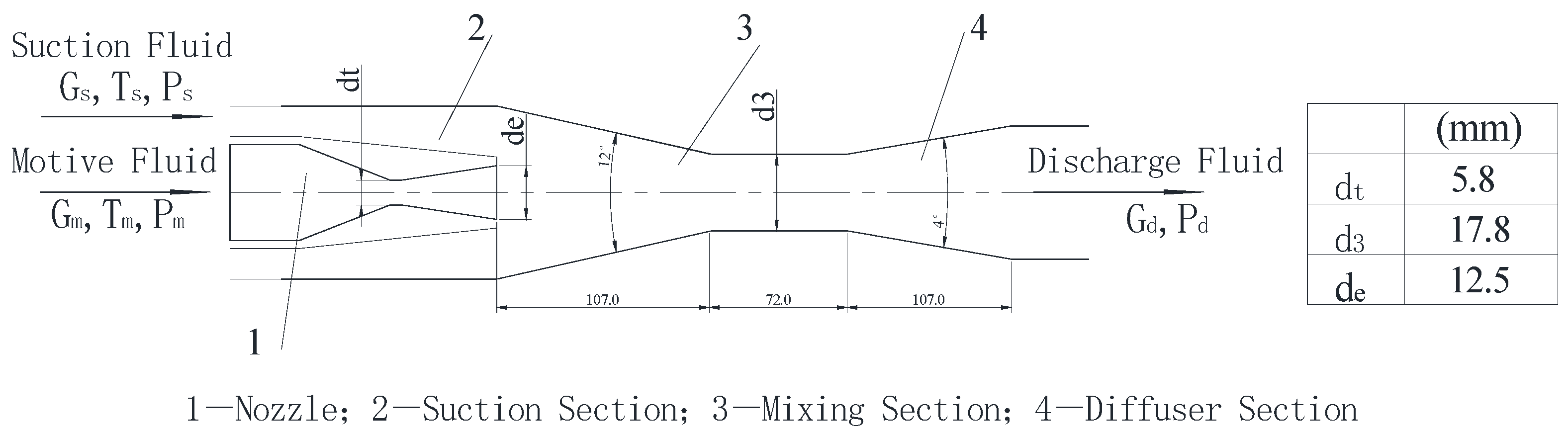
The geometric parameters of the steam ejector analyzed in this study were based on the jet refrigeration cycle system experiment conducted by Chen and Sun [23], as illustrated in Figure 1. To verify the model’s reliability, the simulated operating conditions were kept consistent with those adopted in the reference experiment. Additional operating conditions within the experimental range were then added to support the mechanism analysis of how axial spindle movement affects ejector performance and flow-field characteristics. The primary parameters, including Pm, suction pressure (Ps), discharge pressure (Pd), motive temperature (Tm), and suction temperature (Ts), are presented in Table 1. These temperatures were set at 2 degrees above the saturation pressure–temperature to prevent premature condensation, similar to the experiments.
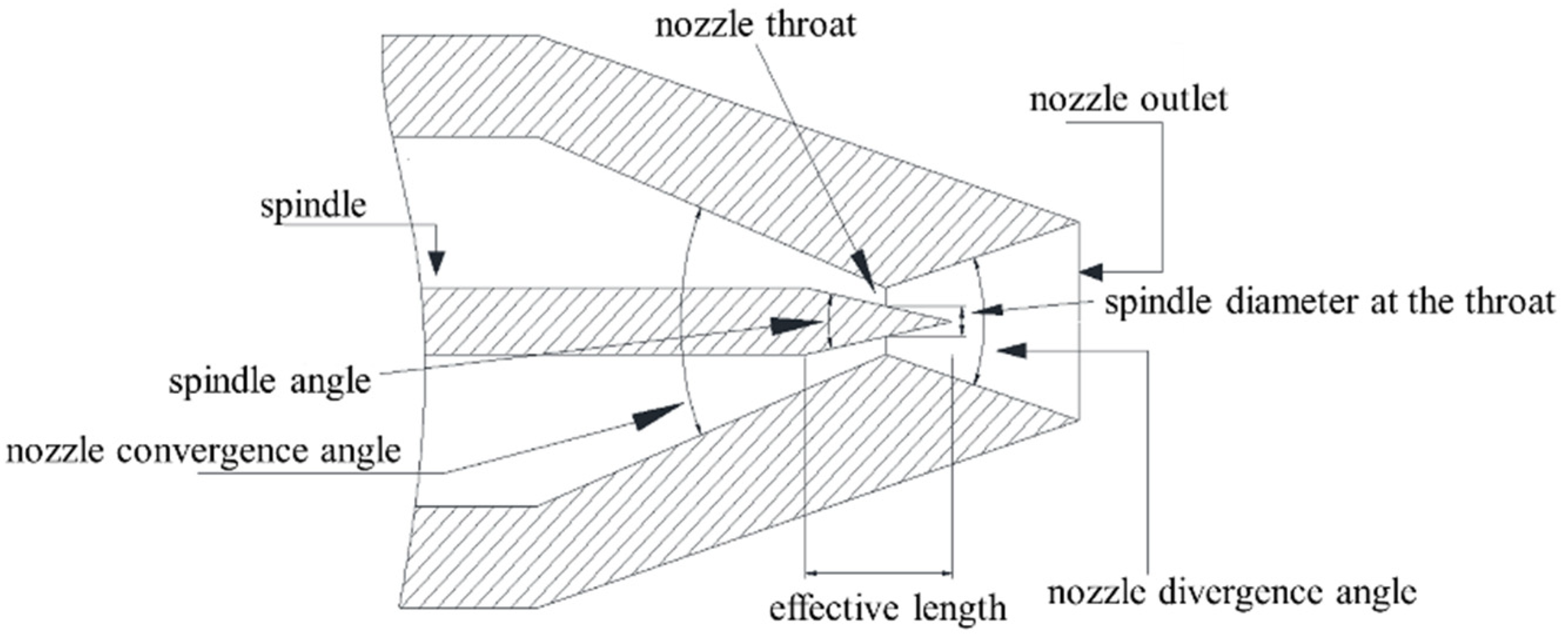
As shown in Figure 2, the adjustable steam ejector simulated in this paper was modified from the fixed steam ejector by introducing a spindle. The diameter of the circle corresponding to the actual flow area at the nozzle throat is defined as the equivalent throat diameter (dt). By adjusting the spindle position, dt can be changed, which subsequently modifies the performance and flow field of the ejector. This regulation mechanism allows the ejector to maintain high efficiency across a wide range of operating conditions [24]. The effective spindle length was set to 35 mm to achieve the maximum adjustment range obtainable by moving the spindle. The spindle position under the design condition was defined as the initial position (x3 = 0), where dt was 5.66 mm. Movement of the spindle toward the nozzle outlet was defined as the positive x-axis direction, while movement toward the nozzle inlet was defined as the negative x-axis direction. A positive movement corresponds to a decrease in dt, while a negative movement corresponds to an increase in dt. A step size of 7 mm was selected, and the range of operating conditions covered the entire process of the spindle moving from the maximum positive position (x = 14 mm) to the maximum negative position (x = −14 mm). Meanwhile, an operating condition without the spindle, in which the spindle was completely removed from the nozzle throat, was introduced for comparison. The correspondence between the spindle axial displacement (x) and dt under each operating condition is illustrated in Table 2.
At the inlet cross-section of the ejector mixing chamber, the motive-fluid velocity is much higher than the suction-fluid velocity. Therefore, disturbances induced by the lateral entry of the suction fluid into the suction chamber were neglected to simplify the model. The ejector flow was simplified as a two-dimensional axisymmetric flow.

2.2. Construction and Optimization of the Mesh

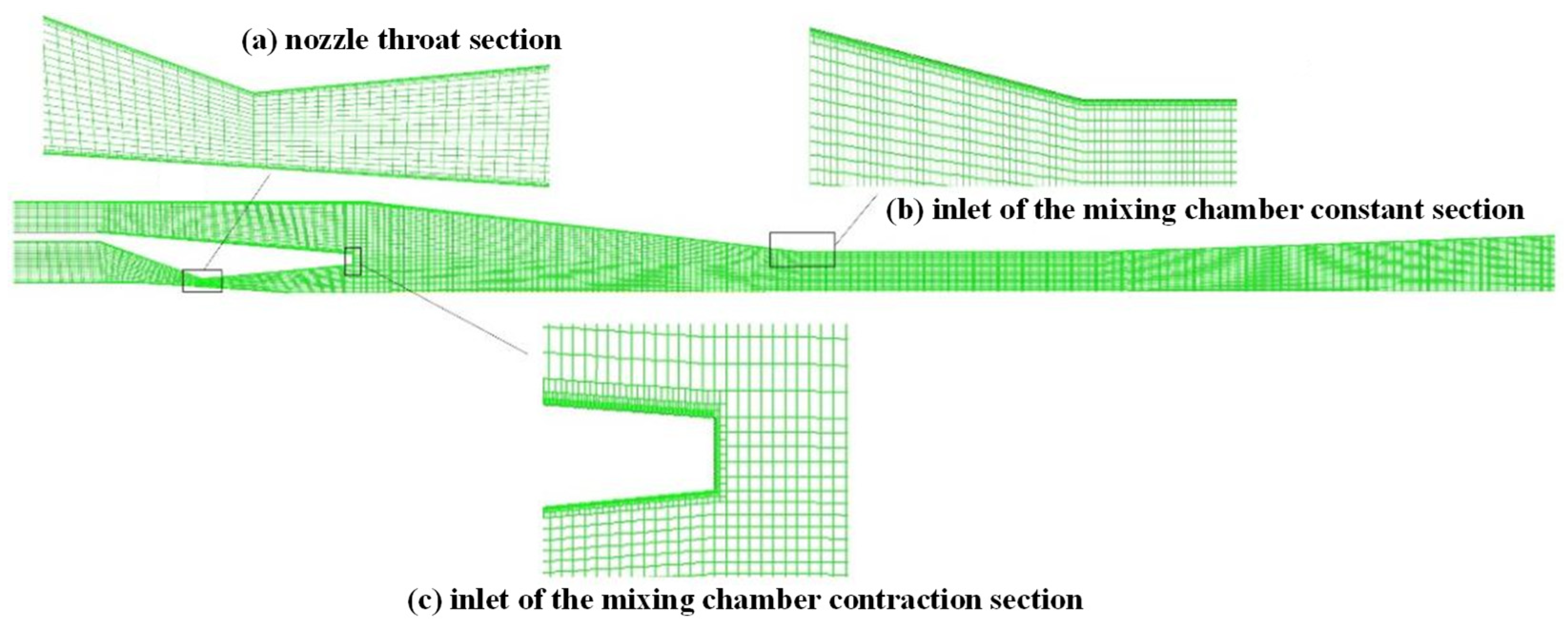
A structured quadrilateral mesh for the two-dimensional axisymmetric model of the steam ejector was generated utilizing ICEM, as shown in Figure 3. The mesh was locally refined in the regions near the nozzle and the central axis, both of which exhibit large velocity gradients and complex supersonic two-phase flow phenomena, including shock waves and non-equilibrium condensation. The near-wall mesh was locally refined to maintain y+ ≈ 1, allowing the viscous sublayer to be resolved and thereby improving the accuracy of the simulation results.
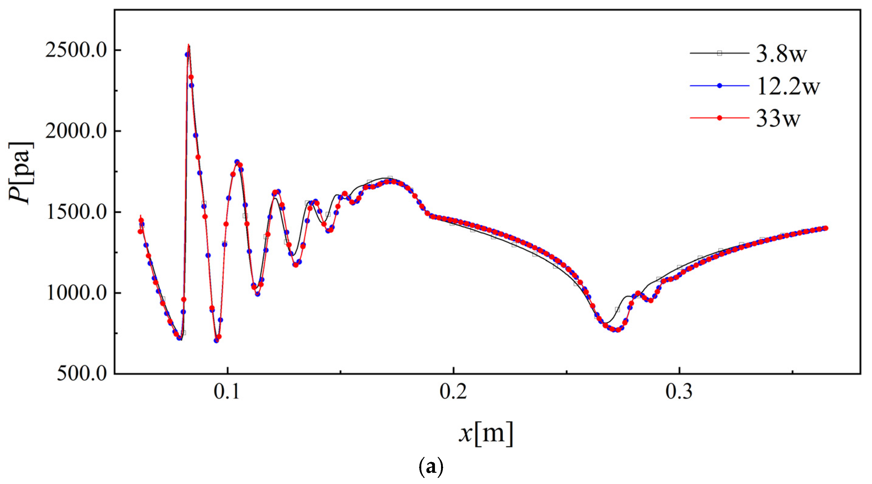
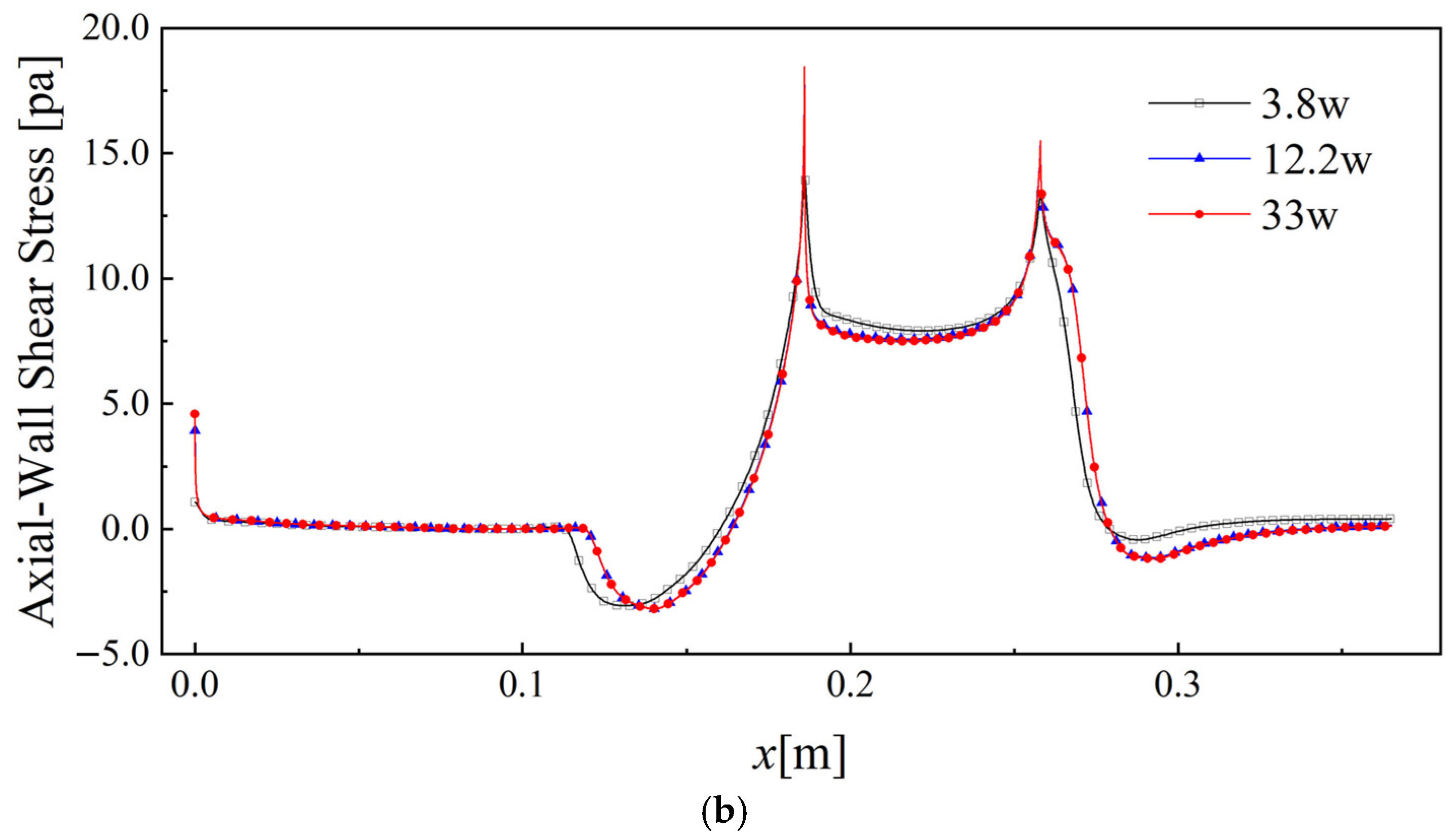
The grid independence verification was conducted for the adjustable steam ejector under the design condition (x3 = 0) utilizing three meshes: a coarse grid with 38 thousand cells, a medium grid with 122 thousand cells, and a fine grid with 330 thousand cells. The verification results are presented in Table 3, showing that the average GCI value is 7.478 × 10⁻³%, which indicates that the medium grid employed in this study fully satisfies engineering standards. In addition, the monitored parameters exhibit a strictly monotonic trend with grid refinement, demonstrating the high reliability of the calculation results. From another perspective, Figure 4 demonstrates that the distributions of axial static pressure and wall shear stress gradually converged with progressive grid refinement. When the grid number was increased from 122 thousand to 330 thousand, the calculation results were almost identical. This phenomenon indicates that a grid number of 122 thousand is sufficient to fulfill the accuracy requirements. Considering both computational accuracy and cost, the two-dimensional grid for the adjustable steam ejector was set to 122 thousand cells.

2.3. Establishment of Mathematical Model and Numerical Solution Methods

Three conservation equations of wet steam at steady state:
𝜕 𝜕 x j ρ v j = 0
𝜕 𝜕 x j ρ v j v i = 𝜕 τ i j 𝜕 x j 𝜕 P 𝜕 x i
𝜕 𝜕 x j v j ρ E + P = 𝜕 𝜕 x j λ eff 𝜕 T 𝜕 x j + 𝜕 𝜕 x j v j τ i j
where τij is the viscous stress tensor and E is the total energy per unit mass of the fluid.
The third-order virial-type equation [25] is used to express the real state of steam:
P = ρ v R T 1 + B ρ v + C ρ v 2
where B and C are given by:
B = a 1 1 + τ α 1 + a 2 e τ 1 e τ 5 2 τ 1 2 + a 3 τ
where τ = 1500/T, α = 10,000.0, a1 = 0.0015, a2 = −0.000942, and a3 = −0.0004882.
C = a τ τ 0 e α τ + b
where τ′ = T/647.286, τ0 = 0.8978, α = 11.16, a = 1.772, and b = 1.5 × 10⁻⁶.
To verify the accuracy of the mathematical model within the operating range considered in this study, a quantitative validation was conducted against the IAPWS-IF97 standard [26]. At the representative sampling point (Pm = 19.8 kPa, Tm = 335 K), the specific volume calculated by the current virial model was 7.7694 m3/kg. Compared with the standard IAPWS-IF97 value (7.7562 m3/kg), the relative error was only 0.17%. This validation result demonstrates that the real gas model provides high-precision thermodynamic predictions in the equilibrium superheated region prior to the onset of non-equilibrium phase change. However, as an equilibrium-based formulation, the virial equation has inherent limitations in describing the rapid non-equilibrium phase-transition process once the steam undergoes intense supersonic expansion and enters the metastable state. It cannot independently characterize the spontaneous nucleation process or the dynamic feedback of latent heat release on the flow field. Therefore, it is essential to couple this equation of state with the non-equilibrium condensation model detailed in the following discussion to accurately capture the complex phase-change characteristics in the metastable region.
The equations for the physical properties of steam and water, as well as those for the saturated steam and liquid lines, are detailed in Reference [27]. Assume that Tl = Tv, Pl = Pv, vl = vg. Furthermore, since the droplet diameter is very small, and ρl is much greater than ρv, it is approximated that:
ρ = ρ v / 1 β
where β is the condensate mass fraction.
This approach can be extended to other physical properties of wet steam:
φ = φ l β + 1 β φ v
where φ represents the following properties of the mixture: specific enthalpy (h), specific entropy (s), specific heat capacity at constant pressure (Cp), specific heat capacity at constant volume (CV), dynamic viscosity (μ), and thermal conductivity (k).
Ma is an important dimensionless parameter for determining the sonic flows:
M a = v / a
where a is the sonic velocity of wet steam [28,29]:
a = ρ β ρ v a v 2 + 1 β ρ l a l 2 1 / 2
The condensation and nucleation of steam that occur during water-vapor flow in the steam ejector are classified as spontaneous condensation. When water vapor is supercooled, the vapor and liquid phases are in thermodynamic non-equilibrium. The core issues in the condensation dynamics of water vapor are nucleation theory and droplet growth theory. In water-vapor condensation, nucleation refers to the formation of tiny molecular clusters (condensation nuclei) when the vapor is in a supercooled state. This process occurs as water-vapor molecules collide and continuously aggregate under the influence of intermolecular forces. Droplet growth is the subsequent process in which water vapor continues to condense onto these nuclei, leading to a further increase in droplet size [30].
The governing equations for the vapor–liquid two-phase mixture are formulated based on the Eulerian coordinate system. Among them, the transport Equation (11) governs β, while Equation (12) governs the number of droplets per unit volume [31]:
div ρ v β = Γ
div ρ v η = ρ J
where Γ is the liquid mass condensation rate [31], which comprises two components: the first term on the right-hand side of Equation (13) represents the mass of liquid generated through spontaneous nucleation, while the second term accounts for the liquid mass produced by droplet growth after nucleation.
Γ = m ˙ l = m ˙ v = 4 3 π ρ l J r 3 + 4 π ρ l η r ¯ 2 𝜕 r ¯ 𝜕 t
where r* is the Kelvin–Helmholtz critical droplet radius, J is the nucleation rate per unit volume [32], r ¯ is the average droplet radius, η is the number of droplets per unit volume, and 𝜕 r ¯ 𝜕 t is the droplet radius growth rate. The following introduces the formulas and solutions for the five variables, r*, J, r ¯ , η, and 𝜕 r ¯ 𝜕 t , through the water-vapor nucleation model and the droplet growth model:
The critical radius r* of condensation nuclei and the supersaturation ratio S are expressed as follows:
r = 2 σ ρ l R T ln S
S = P v P s a t ( T )
As can be seen from Equation (14), condensation nuclei can form only when water vapor is in a supersaturated state (S > 1).
Classical homogeneous nucleation theory describes the process by which a supersaturated phase forms a liquid phase in the form of droplets in the absence of impurities or foreign particles. In this study, a steady-state classical homogeneous nucleation theory model modified for non-isothermal effects was adopted [32]:
J = q c 1 + θ ρ v 2 ρ l 2 σ M m 3 π e 4 π r 2 σ 3 k B T v
where qc is the evaporation coefficient, kB is the Boltzmann constant, Mm is the molecular mass of water, σ is the surface tension of the liquid at temperature T, and θ is the non-isothermal correction factor:
θ = 2 ( γ 1 ) γ + 1 h l v R T h l v R T 0.5
where γ is the adiabatic index, and hlv is the latent heat of condensation, which is obtained by differentiating the saturated steam equation and utilizing the Clausius–Clapeyron relation.
By replacing the liquid-phase parameter distribution of the multicomponent dispersed phase with an averaged homogeneous parameter distribution, the relationship between η and β can be derived:
η = β 1 β V d ρ l / ρ g
where Vd is the average volume of droplets:
V d = 4 3 π r ¯ 3
where r ¯ is the average droplet radius, which can be derived by combining the equations for η and Vd.
r ¯ = 3 β 4 π η ( 1 β ) ( ρ l ρ v ) 3
In this study, the simplified Young–Gyarmathy droplet growth model widely utilized by researchers [32] was adopted as follows:
𝜕 r ¯ 𝜕 t = P h lv ρ l 2 π R T γ + 1 2 γ C l 1 r r ¯ Δ T
where r* is the critical radius. ΔT is the degree of supercooling, defined as the difference between the steam saturation temperature and the steam temperature.
Based on the above, the mathematical model was solved numerically under steady-state conditions utilizing Fluent and the finite-volume method. The implicit solver was based on density coupling that has the excellent adaptability for compressible and supersonic flows. The SST k-ω turbulence model was adopted. y+ ≈ 1 is ensured by refining the near-wall region mesh so that the turbulence model coupling with low Reynolds number boundary conditions is suitable for complex flows. The variable gradient interpolation method adopted the Green–Gauss method based on nodes. The convection and the condensation terms were all discretized by the second-order upwind scheme. The convective flux type was the Roe-FDS scheme, which is suitable for treating steady shock waves. The convergence criterion of the continuity term was set to 1 × 10⁻⁸, and convergence was determined by the net flux difference between the calculated two-phase flow pattern and the global flux. It is assumed that all walls are adiabatic smooth solid, and the boundary conditions are no slip and no penetration. Given that inlet pressures, outlet pressures, and inlet temperatures are constant.
Furthermore, a detailed discussion regarding the sensitivity and limitations of the numerical model (such as turbulence models) was provided in our previous study [33], where a comprehensive model comparison and uncertainty analysis were conducted.

2.4. Model Verification

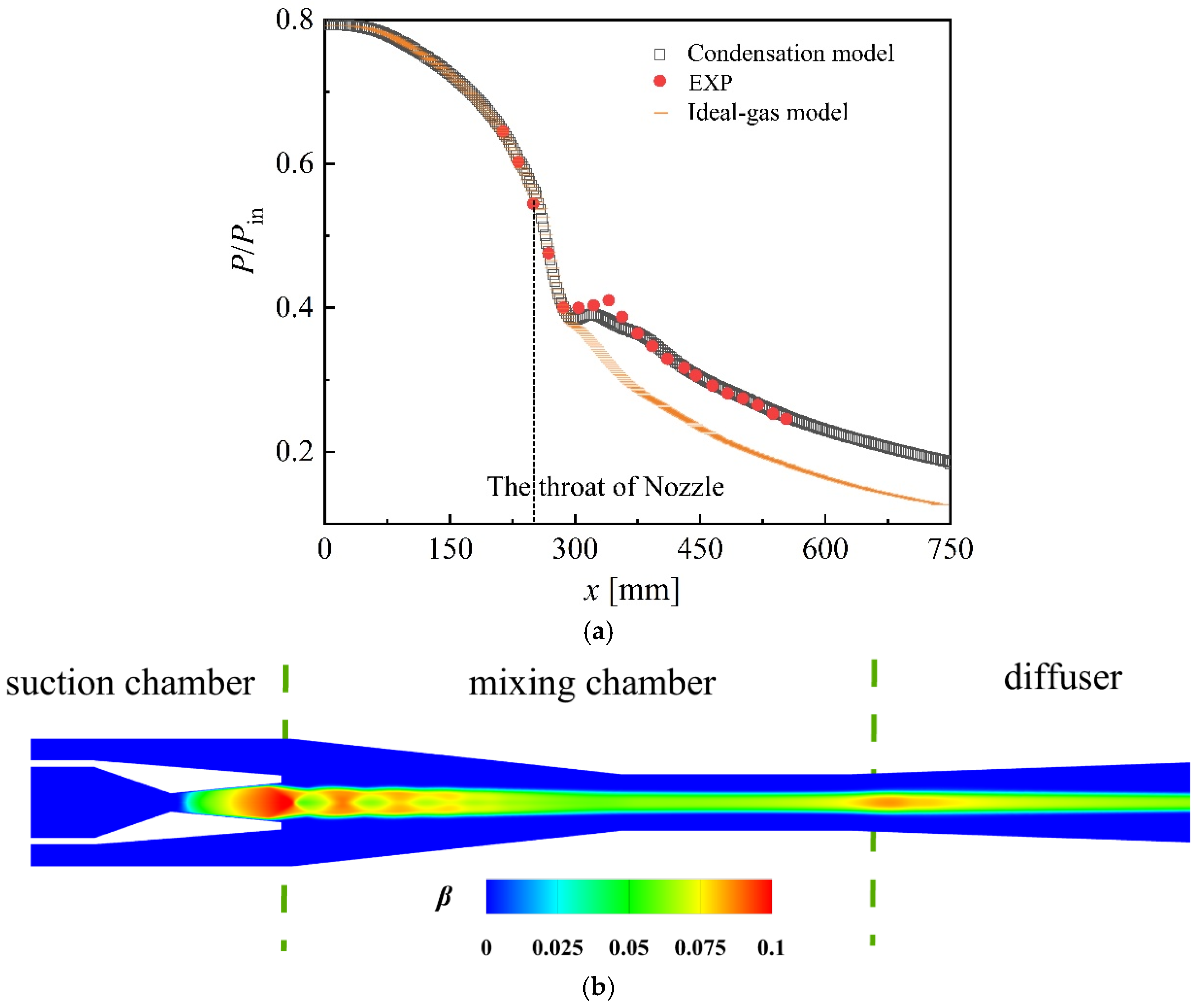
To verify the accuracy of the numerical model presented in this study, the simulation results were compared with experimental data in various aspects (including local complex flow phenomena and ejector performance). For the verification of internal complex flow phenomena, the axial static pressure ratio (P/Pin) obtained from the numerical simulation was compared with the experimental results of Moore et al. [34], as illustrated in Figure 5a. The average relative error was 1.9%, indicating good agreement with the experimental data. The location of the abrupt change in P/Pin is the position of the condensation shock wave. The ideal gas model fails to capture the condensation shock waves due to its neglect of condensation effects. In contrast, the condensation shock wave location predicted by the non-equilibrium condensation model in this study closely matched the experimental results, with a relative error of 2.67% of the total nozzle length. Furthermore, Chen and Sun [23] observed condensation droplets throughout the entire mixing chamber (including the contraction and constant-area sections). Correspondingly, the distribution of β predicted by the non-equilibrium condensation model utilized in our research accurately matched these regions (Figure 5b). This consistency provides strong experimental support for the ability of our model to reliably predict β under different spindle positions. The comparison between the simulation results and the experimental results of Chen and Sun [23] regarding ejector performance is presented in Table 4. The simulation results fitted the experimental data well, with an average relative error of 3.65% and a maximum relative error of 7.6%. The above comparison not only verifies the reliability of the CFD model presented in this study but also demonstrates the limitations of the ideal gas model and underscores the necessity of utilizing non-equilibrium condensation models. However, certain limitations also exist in the CFD model utilized in this study. For instance, a long spindle and the associated wake may generate inherently three-dimensional features, which might slightly alter the predicted shock dynamics near the spindle tail. Nevertheless, a recent comprehensive review by Arabbeiki et al. [35] confirms that two-dimensional axisymmetric CFD modeling remains the predominant approach globally for spindle-based ejectors to balance accuracy and computational cost. Building upon this consensus, the recent numerical studies investigating steam ejectors equipped with movable spindles, such as the study by Dolgun et al. [16], continue to successfully employ two-dimensional axisymmetric simulations. Furthermore, local shock-boundary-layer interaction and backflow may exhibit unsteady behavior, which means that the steady-state solver might average out instantaneous shock oscillations and transient condensation phenomena. The adiabatic-wall assumption neglects external heat dissipation, which could lead to a slight overestimation of the near-wall fluid temperature and potentially delay the calculated onset of non-equilibrium condensation. Nevertheless, as explicitly validated by experimental studies specifically targeting spindle-equipped steam ejectors such as Varga et al. [36], the combination of two-dimensional axisymmetric, steady-state, and adiabatic assumptions still yields highly accurate macroscopic predictions, with average relative errors typically below 10%. Therefore, since the primary focus of this study is to evaluate the macroscopic Er and time-averaged flow–thermal–phase-change coupling characteristics, these localized transient and near-wall thermal deviations are considered minor and do not compromise the overall reliability of the global performance results. Furthermore, to maintain scientific rigor and avoid the overgeneralization of conclusions, a clear distinction is established between the directly validated results and those primarily based on numerical interpretation. Specifically, the characteristics, including the pressure ratio, the location of the condensation shock wave, and the appearance location of the condensation liquid, were directly validated against experimental data. In contrast, the intricate internal flow mechanisms discussed subsequently, such as the wake effects, backflow suppression, local temperature rise, and condensation suppression, are results obtained through numerical simulation.

3. Performance Response and Regulation Mechanisms of Adjustable Steam Ejectors Under Varying Pressure Operating Conditions

3.1. Performance Response and Regulation Mechanisms of Adjustable Steam Ejectors Under Varying Discharge Pressure Operating Conditions

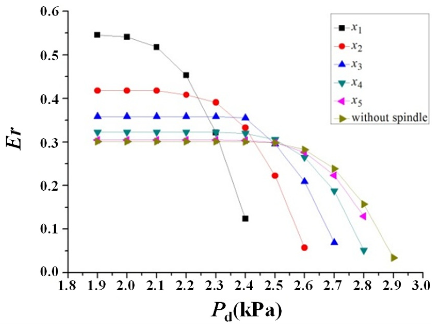
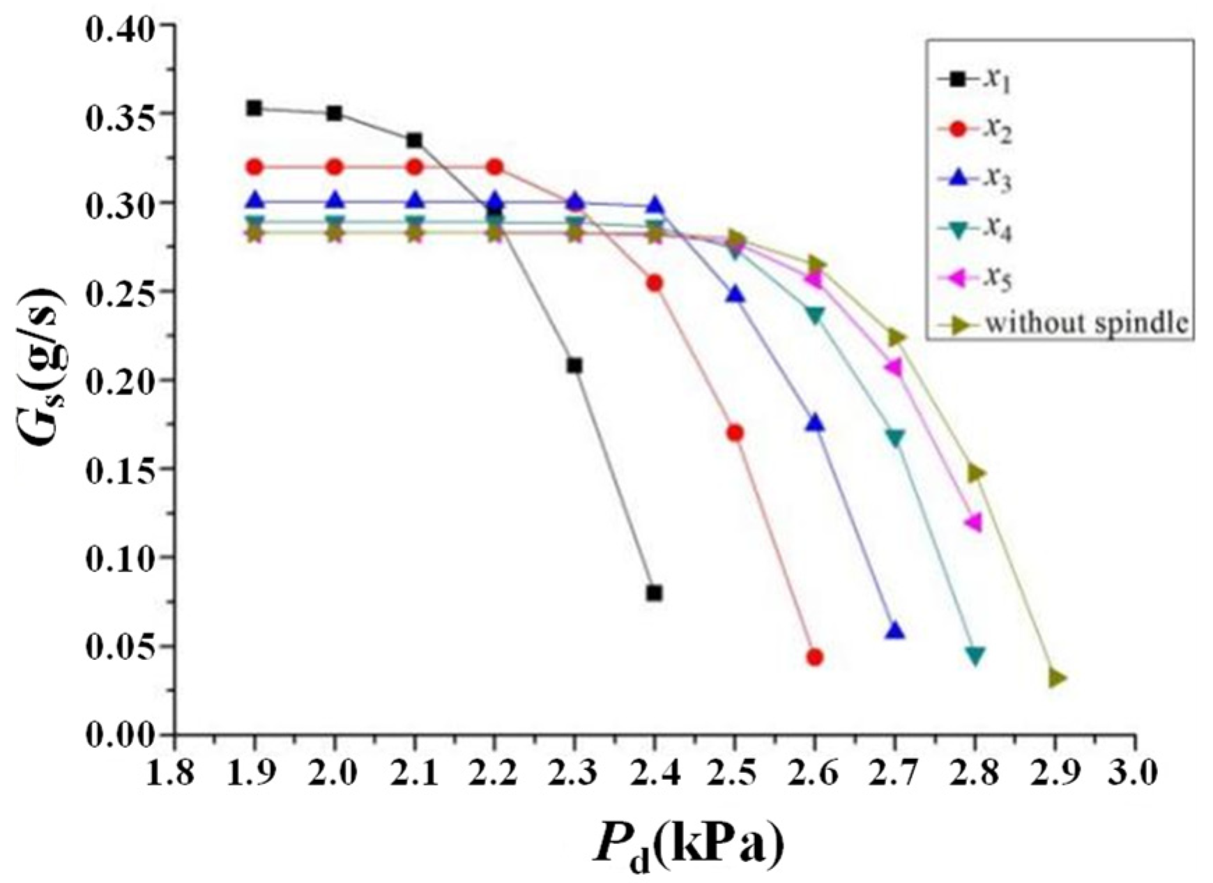
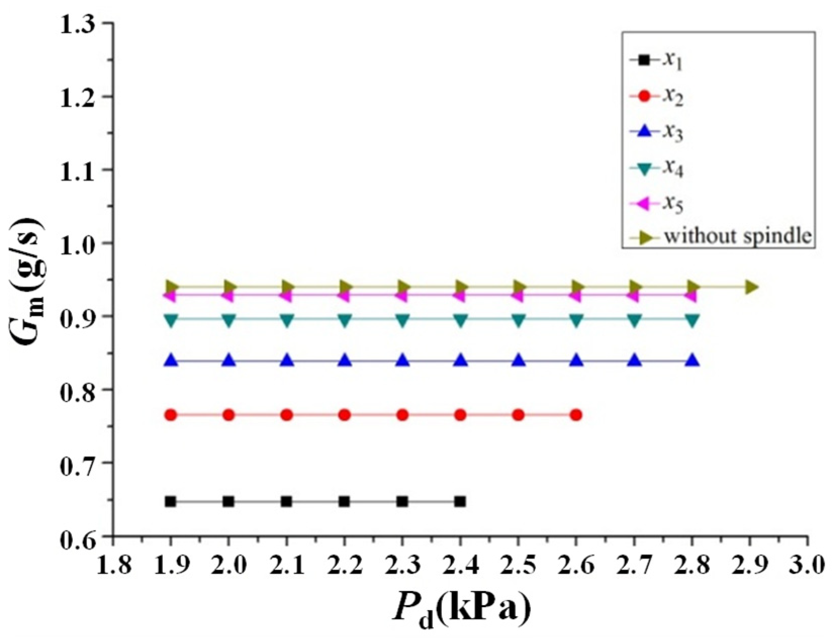
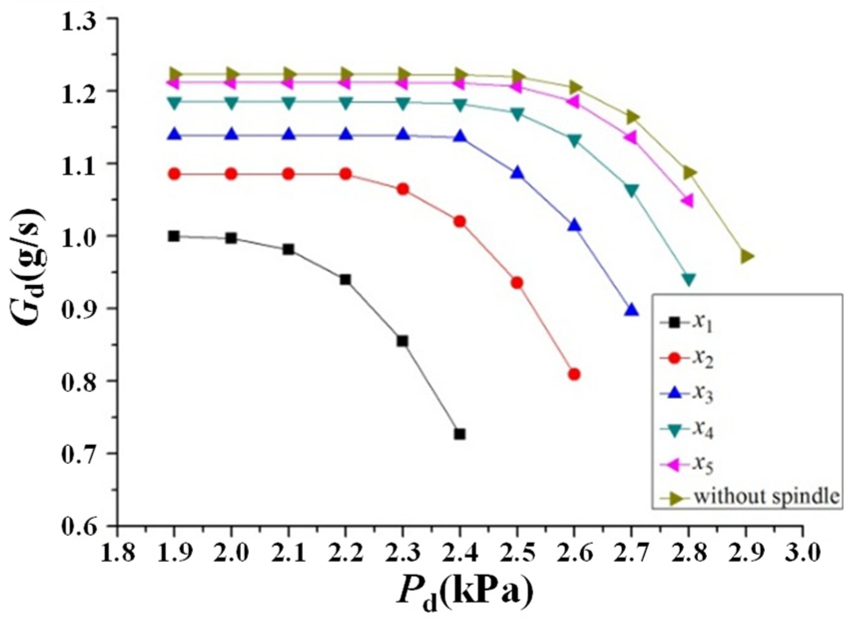
The variations in Er and the mass flow rates (Gm, the suction-fluid mass flow rate (Gs), and the discharge-fluid mass flow rate (Gd)) with varying discharge pressure (Pd) of the adjustable steam ejector, for different axial positions of the spindle under the operating conditions of Pm = 19.8 kPa and Ps = 1.8 kPa, are illustrated in Figure 6, Figure 7, Figure 8 and Figure 9. x3 is designated as the initial position of the spindle. Movement of the spindle in the positive x-axis direction (towards x2 and x1) results in a decrease in dt, while movement in the negative direction (towards x4 and x5) results in an increase in dt.
As illustrated in Figure 6, the ejector transitions from the critical state to the sub-critical state as Pd increases. In the sub-critical region, Er is significantly affected by Pd, exhibiting instability characterized by a sharp decline as Pd increases. A larger dt results in a broader critical region and thus a higher critical Pd, whereas the corresponding critical Er is lower. Moreover, at larger dt, Er decreases more gradually with increasing Pd in the sub-critical region, indicating higher stability.
The above performance changes are governed by the flow-regulation mechanism of the adjustable steam ejector. Taking the critical state at Pd = 1.9 kPa as an example, increasing dt decreases AR, thereby reducing the pressure difference between the nozzle outlet and the suction fluid, which in turn decreases Gs, as illustrated in Figure 7. However, the flow area of the nozzle throat is directly enlarged as dt increases, resulting in a substantial rise in Gm through the nozzle (Figure 8). An increase in the total Gd with increasing dt is depicted in Figure 9, implying that the increase in Gm outweighs the decrease in Gs. Since Er is defined as the ratio of Gs to Gm, both an increase in Gm and a decrease in Gs contribute to a reduction in the critical Er. As dt increases, Gm becomes larger, imparting greater energy and improved resistance to disturbances caused by Pd. Consequently, the critical Pd at which the suction-fluid choking state is disrupted becomes higher, thereby delaying the decrease in Gs and broadening the critical region.
The performance response to spindle movement can be quantified by comparing numerical simulation results for ejectors with the spindle at different positions under the identical operating conditions (Pm = 19.8 kPa, Ps = 1.8 kPa, Pd = 1.9 kPa). As shown in Figure 6, moving the spindle from the initial position x3 (dt = 5.66 mm) to position x1 (dt = 5.00 mm) along the positive x-axis causes dt to decrease by 11.7%. The critical Er increases from 0.36 to 0.55, corresponding to a 52.8% improvement. However, this enhancement is accompanied by a reduction in the critical Pd, which falls from 2.4 kPa to 2.0 kPa, a decrease of 16.7%. Conversely, moving the spindle in the negative x-axis direction to the position where dt is 6 mm leads to a 6% increase in dt. In this case, the critical Er decreases from 0.36 to 0.30, corresponding to a 16.7% decrease, while the critical Pd increases from 2.4 kPa to 2.5 kPa, corresponding to a 4.2% increase.
Therefore, adjusting the spindle position allows the adjustable steam ejector to adapt to different Pd conditions. When the spindle is moved in the positive x-axis direction and dt decreases, the ejector is more applicable to relatively low Pd conditions, resulting in a higher Er and improved performance. When the spindle is moved in the negative x-axis direction and dt increases, the ejector becomes more suitable for high Pd conditions, which broadens the critical region, expands the adjustable Pd range, and enhances operational stability.

3.2. Performance Response and Regulation Mechanisms of Adjustable Steam Ejectors Under Varying Motive Pressure Operating Conditions

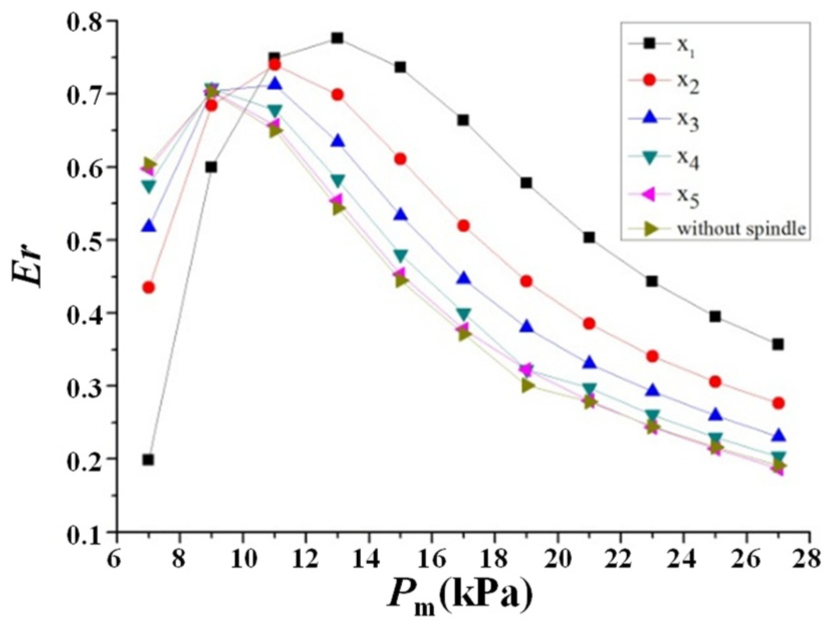
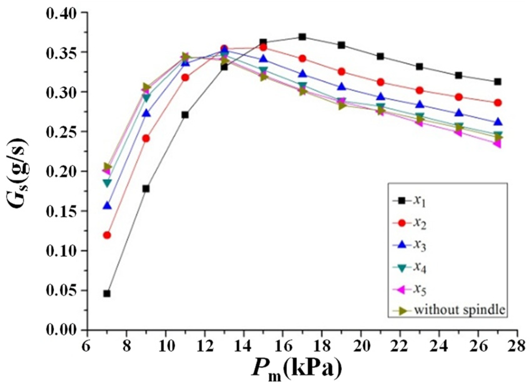
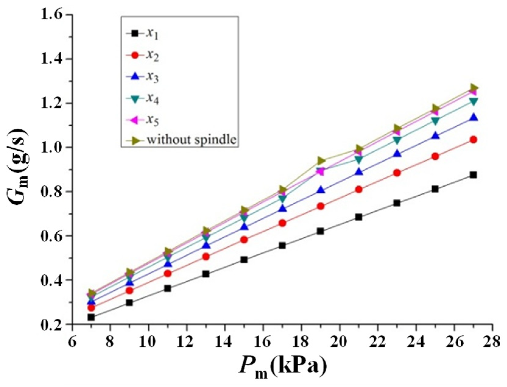
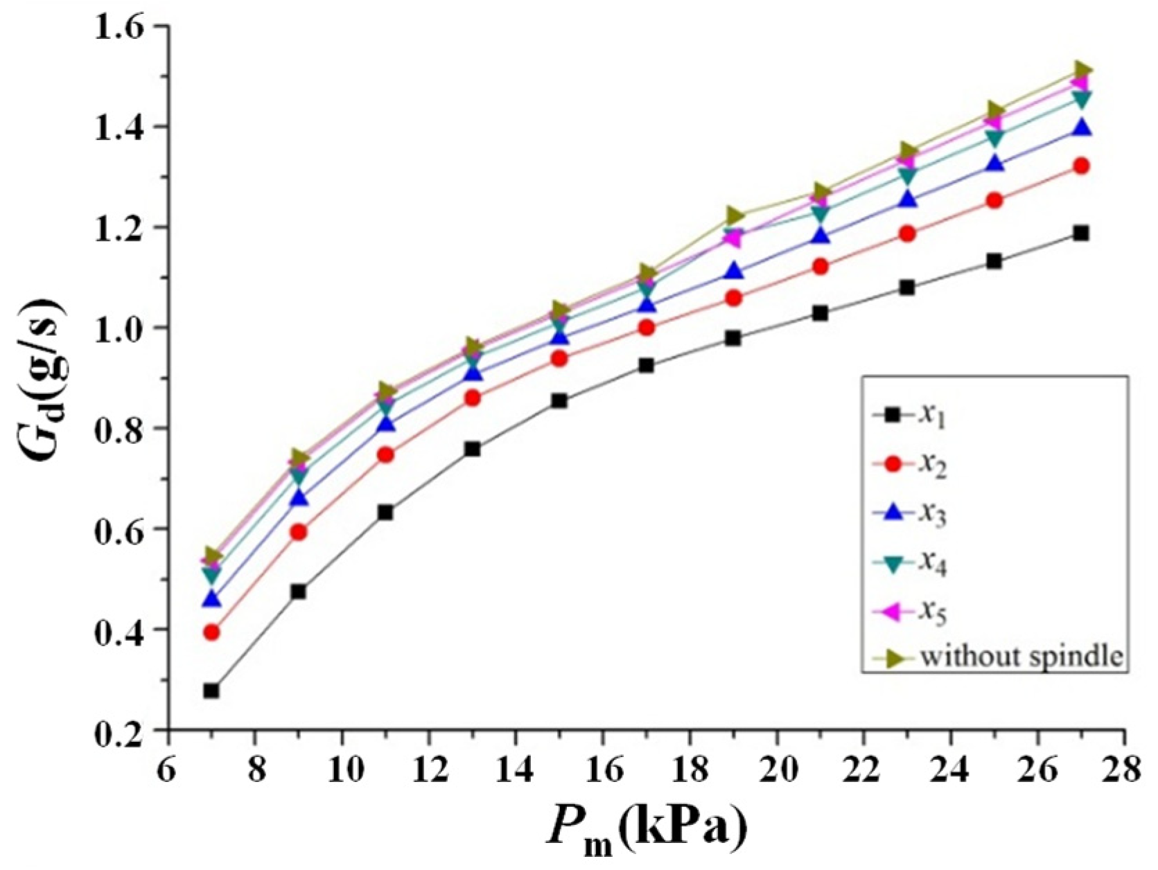
The variations in Er and mass flow rate with varying Pm of the adjustable steam ejector are illustrated in Figure 10, Figure 11, Figure 12 and Figure 13 for different axial positions of the spindle under the operating conditions of Ps = 1.8 kPa and Pd = 1.7 kPa.
As illustrated by the performance curves in Figure 10, the operating state of the ejector gradually shifts from the sub-critical state to the critical state as Pm increases. In the sub-critical state of the ejector, a larger dt causes Er to increase more gradually with Pm. Meanwhile, the sub-critical region becomes narrower, and Er under the same operating conditions becomes larger. The above performance changes are governed by the flow-regulation mechanism. Figure 11 and Figure 12 illustrate that both Gm and Gs increase with increasing dt under low-pressure operating conditions. Moreover, the increase in Gs is significantly greater than that in Gm in both magnitude and rate, indicating that a larger nozzle throat area is beneficial for entraining more suction fluid under low-pressure driving, thereby increasing Er. Conversely, in the critical state of the ejector, when dt increases, the critical region becomes wider, whereas the critical Er decreases under the same operating conditions. The phenomenon can be attributed to the internal mass flow competition and choking mechanism in the flow field: Gm consistently increases linearly with increasing dt. However, as Pm increases further, the high-energy motive fluid undergoes intense expansion at the mixing chamber inlet, occupying excessive effective flow area. As illustrated in Figure 11, the growth rate of Gs is gradually decreased by this expansion, and negative growth can even occur at large dt. The continuous increase in Gm, combined with the limited or even decreased growth of Gs, results in a decrease in Er as dt increases.
The performance response to the spindle movement can be quantified by comparing the adjustable ejector’s performance at different positions under the identical operating conditions, as illustrated in Figure 10. At low Pm (10 kPa, for example), the initial position x3 of the spindle is in the unstable sub-critical region. If the spindle is moved in the negative x-axis direction to increase dt (such as to positions x4 and x5), the ejector can transition into the stable critical state. At high Pm (27 kPa, for example), the ejector operates in the critical state. Moving the spindle from x3 to x1 in the positive x-axis direction results in an 11.7% decrease in dt and an increase in Er from 0.23 to 0.36, corresponding to a 56.5% rise. Conversely, moving the spindle in the negative direction to the non-spindle state increases dt by 6%, decreasing Er to 0.19, which represents a 17.4% reduction.
Accordingly, decreasing dt by moving the spindle in the positive x-axis direction makes the ejector suitable for high Pm operating conditions, resulting in a larger Er and improved efficiency. In contrast, increasing dt by moving the spindle in the negative x-axis direction makes the ejector more appropriate for low Pm conditions, thereby broadening the critical region and enhancing operational stability.

3.3. Performance Response and Regulation Mechanisms of Adjustable Steam Ejectors Under Varying Suction Pressure Operating Conditions

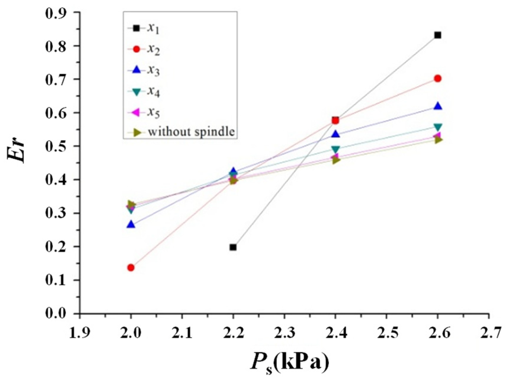
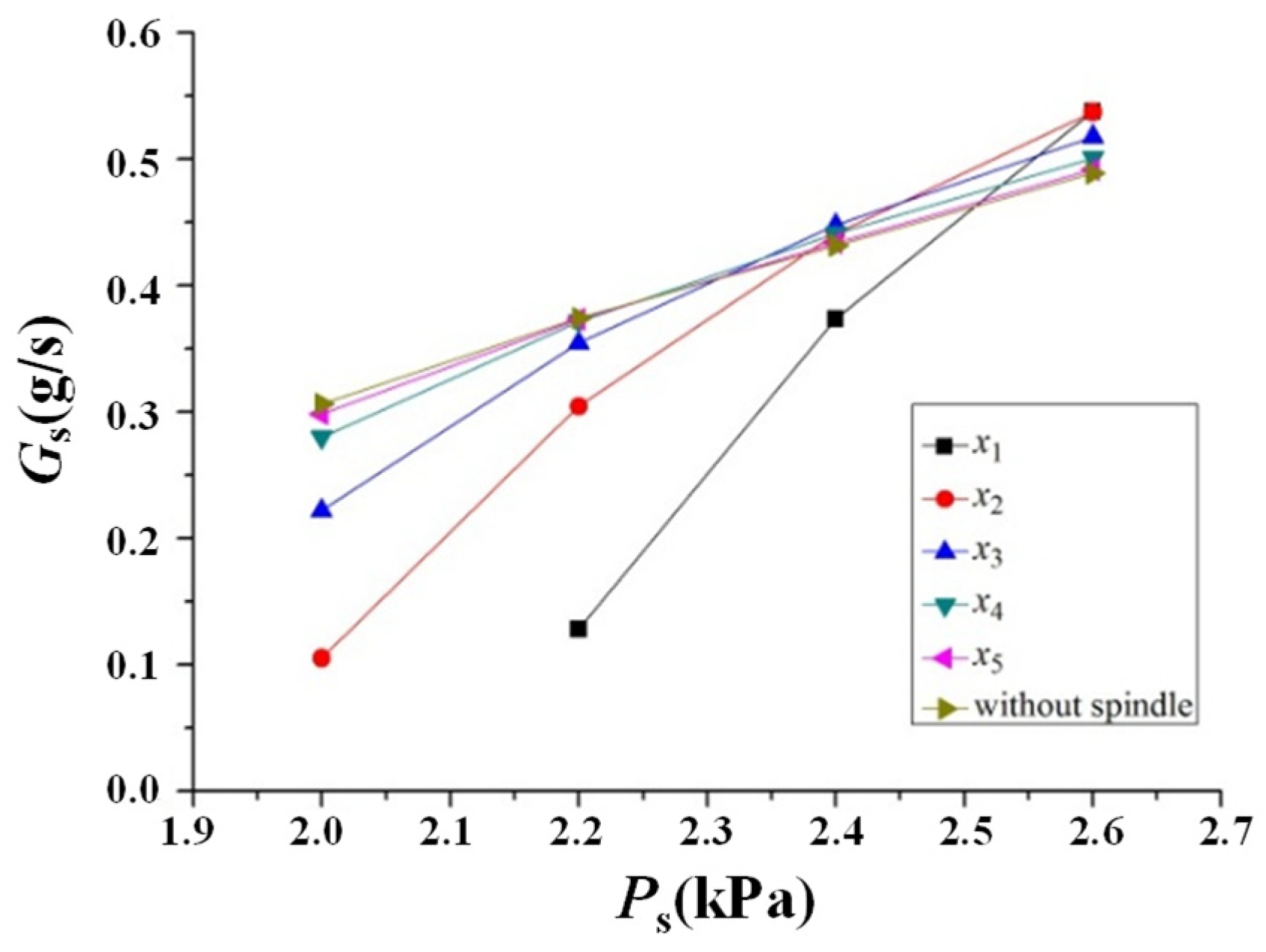
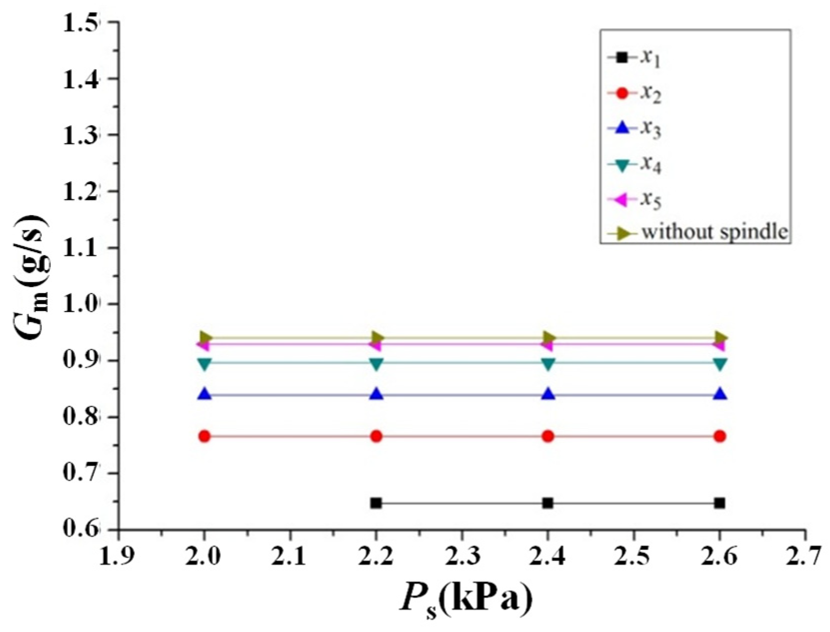
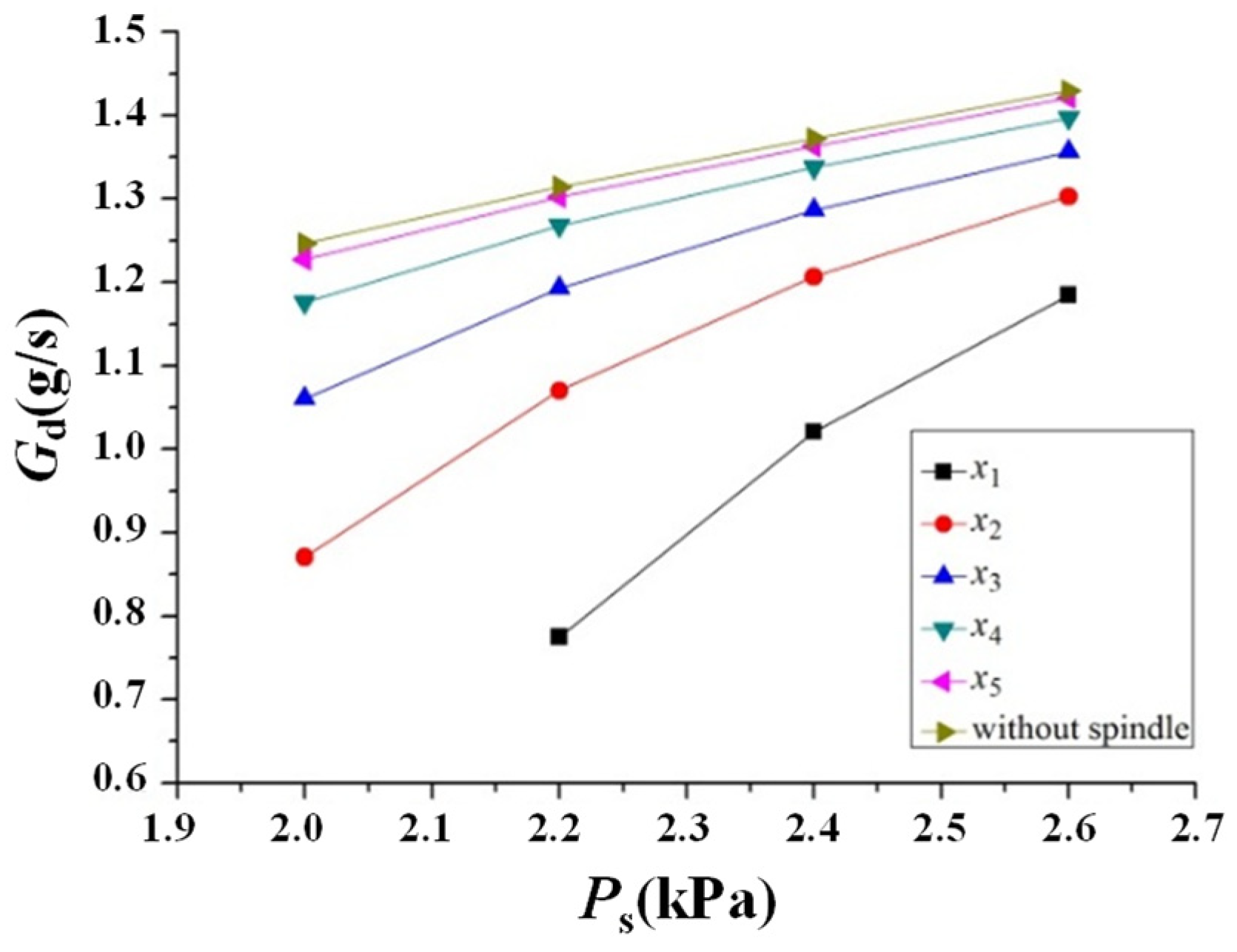
The variations in Er and mass flow rate with varying Ps of the adjustable steam ejector are illustrated in Figure 14, Figure 15, Figure 16 and Figure 17 for different axial positions of the spindle under the operating conditions of Pm = 19.8 kPa and Pd = 2.7 kPa.
Figure 14 demonstrates that the sensitivity of ejector performance to Ps is significantly influenced by dt. As dt decreases, the variation in Er with Ps becomes more pronounced, with higher Er at high Ps and a substantial attenuation of performance at low Ps. Figure 16 reveals that Gm remains constant with varying Ps due to fixed motive steam conditions and the choking state at the nozzle throat. Consequently, Gs is the only factor that determines the variation in Er. At low Ps, the suction fluid has limited energy. Its entry into the mixing chamber depends primarily on viscous shear and entrainment by the high-speed motive fluid. Reducing dt decreases both the momentum flux and effective contact area of the motive fluid, which greatly reduces its ability to entrain the suction fluid. Therefore, ejectors with smaller dt exhibit much lower Gs in low-pressure regions compared to those with larger dt. However, as Ps increases, a larger driving pressure difference between the suction fluid and the mixing chamber is established, facilitating the entrainment of the suction fluid into the flow field. Meanwhile, Gs is constrained by both the motive-fluid suction capacity and the effective flow channel area. Although a reduction in dt leads to a decrease in Gm, it also weakens the aerodynamic choking effect at the mixing chamber inlet, thereby providing a larger effective flow area for the suction fluid. For small dt under high Ps, Gs increases more significantly than it does at large dt, resulting in a rapid enhancement of Er, as shown in Figure 15.
The adjustment effect is clearly demonstrated and quantified by comparing the adjustable ejector’s performance at different positions under identical operating conditions. At low Ps, such as 2.0 kPa, moving the spindle from the design point x3 to x2 along the positive x-axis direction (dt decreases from 5.66 mm to 5.37 mm, a reduction of 5.1%) causes Er to drop sharply from 0.26 to 0.13 (a 50% decrease). Conversely, moving the spindle in the negative x-axis direction to the condition without the spindle (dt increases to 6 mm, a 6% increase) causes Er to rise to 0.33 (a 26.9% increase). However, under high Ps conditions, such as 2.6 kPa, the effect is completely reversed. When the spindle is moved from x3 to x1 in the positive x-axis direction (dt decreases by 11.7%), Er increases sharply from 0.62 to 0.83 (a 33.9% rise). When the spindle is moved in the negative x-axis direction to the non-spindle condition (dt increases by 6%), Er drops to 0.52 (a 16.1% decrease).
Therefore, adjusting the spindle position enables the ejector to flexibly adapt to varying Ps conditions. When the system operates under high Ps conditions, the spindle should be moved in the positive x-axis direction to achieve a higher Er. Under low Ps conditions, the spindle should be moved in the negative x-axis direction to increase dt, thereby enhancing the motive-fluid entrainment capability. This adjustment ensures that high suction capacity and stable performance are maintained even under low-pressure conditions.

4. Evolution of the Flow Field and Multi-Field Coupling Mechanisms in the Adjustable Steam Ejector

4.1. Mechanism of Pressure Field Evolution

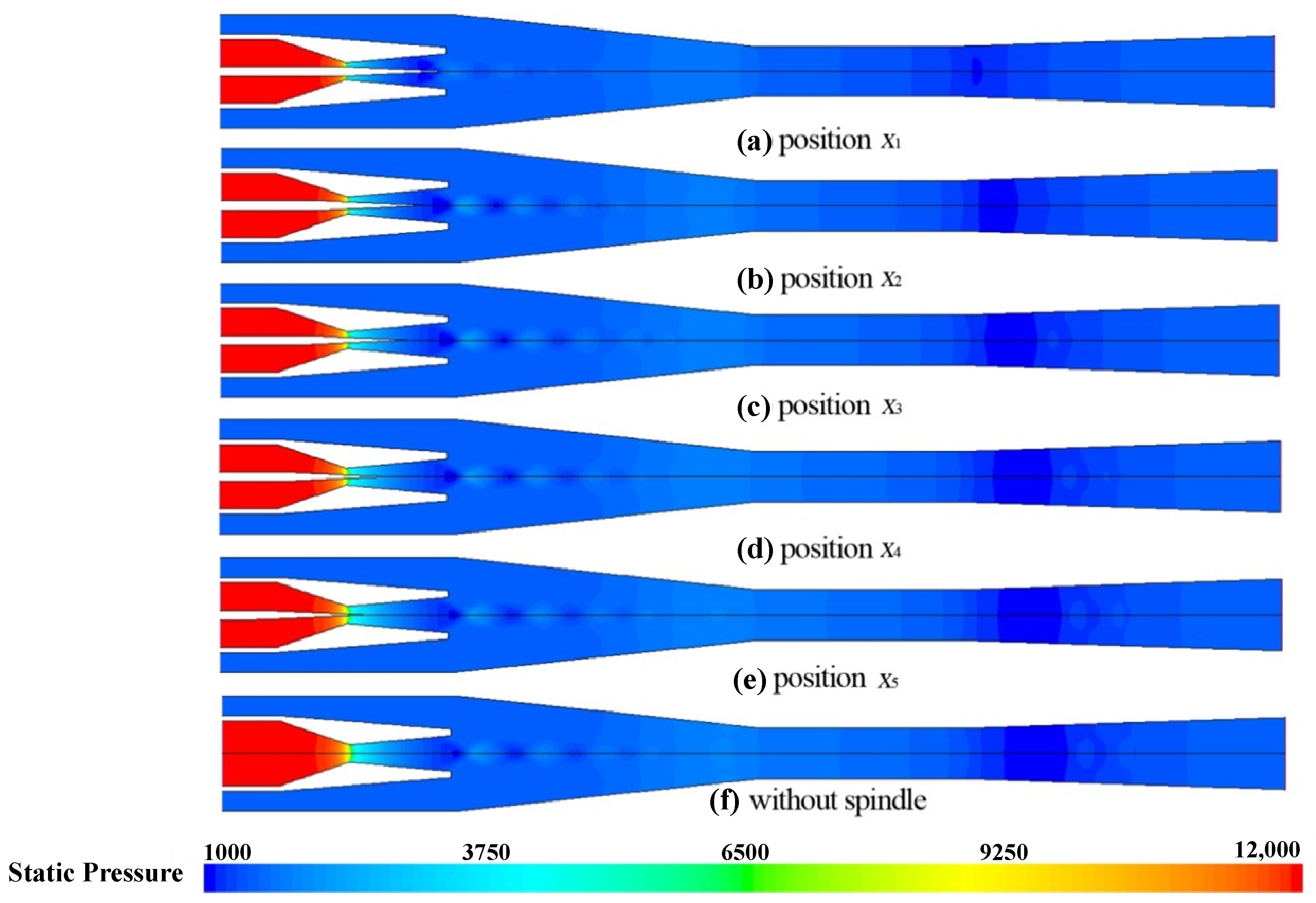
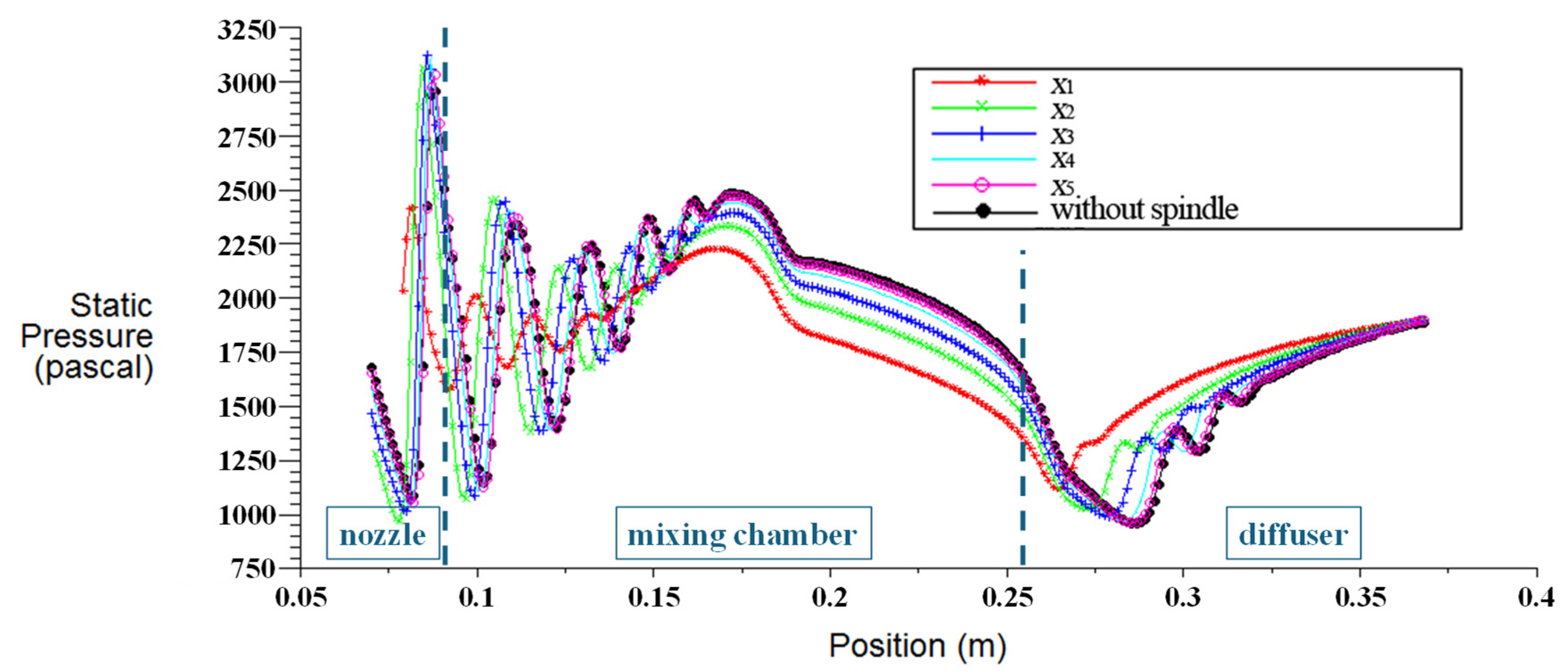
The spindle was moved along the x-axis under fixed operating conditions (Pm = 19.8 kPa, Ps = 1.8 kPa, and Pd = 1.9 kPa). The static pressure contours of the steam ejector and the corresponding axial static pressure distributions at various spindle positions are illustrated in Figure 18 and Figure 19.
Figure 18 illustrates the pressure-potential-energy release mechanism of steam in the adjustable steam ejector, the evolution of the shock train, and the effect of the spindle position on the flow field. After passing through the Laval nozzle, the motive fluid rapidly expands and converts pressure potential energy into kinetic energy. This expansion causes a sharp decrease in static pressure and generates a low-pressure region at the mixing chamber inlet, where the local pressure is lower than the suction pressure. The resulting pressure gradient acts as a direct driving force to draw the suction fluid into the ejector’s suction chamber. When the spindle is located in the nozzle, it occupies the central region of the throat, changing the nozzle-throat cross-section from circular to annular. As the spindle position changes, dt also varies, resulting in different degrees of effective motive-fluid expansion and varying pressure differences between the nozzle outlet and the suction fluid, as presented in Figure 19. The motive fluid then enters the mixing chamber together with the suction fluid. In the contraction section of the mixing chamber, the expansion and compression effects of the supersonic jet induce multiple distinct pressure rises (shock waves) and drops (expansion waves), which constitute a series of typical diamond-shaped shock trains. The diamond-shaped shock trains result from the repeated refraction and interaction of shock and expansion waves within the shear mixing layer formed by the motive and suction fluids. Before encountering the shock wave, the fluid continues to expand, and the pressure keeps decreasing. After passing through the shock wave, the fluid is compressed, and the pressure rises sharply. Subsequently, expansion waves formed by the reflection of the shock wave from the shear mixing layer cause the pressure to drop again. Furthermore, these adjacent wave structures do not exist in isolation but continuously interact. The expansion wave generated by the upstream reflection intersects with the downstream compression wave, forming a highly complex inter-wave interference region. This continuous intersection and interaction of wave structures significantly enhances the local turbulent shear stress, causing part of the fluid’s kinetic energy to be irreversibly converted into internal energy. As the fluid flows downstream through the contraction section of the mixing chamber, the shear mixing layer between the suction fluid and the motive fluid continues to thicken, and intense viscous mixing then rapidly dissipates mechanical energy. Meanwhile, the wall of the contraction section exerts continuous compression on the flow. Influenced by these factors, the shock wave intensity gradually decreases along the flow direction. Consequently, the distinct diamond-shaped shock train becomes increasingly blurred and eventually vanishes within the contraction section of the mixing chamber. In the constant section of the mixing chamber, the suction and motive fluids become more thoroughly mixed. The pressure decreases due to wall friction losses experienced by the high-speed flow, as well as irreversible mixing losses resulting from intense momentum exchange between the two streams. Eventually, the mixed fluid further converts kinetic energy into pressure in the diffuser to reach the required Pd, thereby raising Ps from a low to a medium level. As illustrated in Figure 18, dt increases continuously as the spindle moves from x1 to x5 along the negative x-axis. The jet at the nozzle outlet is no longer confined to the narrow annular channel, and it exhibits more pronounced expansion behavior. Meanwhile, the low-pressure region near the nozzle outlet broadens significantly, indicating a more complete release of pressure potential energy.
The quantitative effect of spindle position on the axial pressure distribution is further revealed in Figure 19. When the spindle moves from the design point x3 to x1 along the positive x-axis direction, dt decreases from 5.66 mm to 5 mm (an 11.7% reduction), and Gm decreases from 0.84 g/s to 0.65 g/s (a 22.6% reduction, as shown in Figure 8). Owing to the reduced motive-fluid momentum, the jet-core energy is reduced, resulting in significant changes in the flow-field characteristics: the shock wave position shifts toward the negative x-axis and enters the divergent section within the nozzle. Furthermore, when the spindle moves from x3 to x1, the distance between adjacent shock waves decreases (by about 14.1%). Specifically, taking the distance between the second and third shock waves as a reference (since the spindle still occupies the symmetry axis when positioned at x1, rendering the data for the first shock wave inaccessible), this spacing decreases from 0.0199 m at x3 to 0.0171 m at x1. Meanwhile, due to the dissipation of shock wave energy during fluid mixing, the amplitude of pressure fluctuations decreases along the flow direction (by about 21.9%). Moreover, the shock wave intensity in the diffuser weakens, the number of shock waves decreases, and their positions shift in the negative x-axis direction. The mixed fluid pressure then increases more gradually, ultimately reaching 1.9 kPa at the ejector outlet. Conversely, as the spindle moves from the design point x3 in the negative x-axis direction until it is eventually removed (corresponding to the condition without the spindle), dt gradually increases from 5.66 mm to 6 mm (a 6% increase), and Gm increases by 11.9%. The enhanced motive-fluid energy pushes the shock wave position in the positive x-axis direction. The shock train strength is significantly increased, as indicated by a 9.9% rise in the amplitude of pressure fluctuations. Meanwhile, the shock train is sustained over a longer distance in the mixing chamber (an increase of about 4.2%).
In summary, the spindle regulates the motive-fluid momentum by varying dt, thereby influencing flow characteristics such as shock waves and the width of the low-pressure region. Meanwhile, this process also reconstructs the energy distribution within the flow field. This flow-field adaptation mechanism constitutes the fundamental basis for the ejector to achieve optimal pressure matching and efficient operation under various operating conditions.

4.2. Evolution Mechanism of the Ma Field

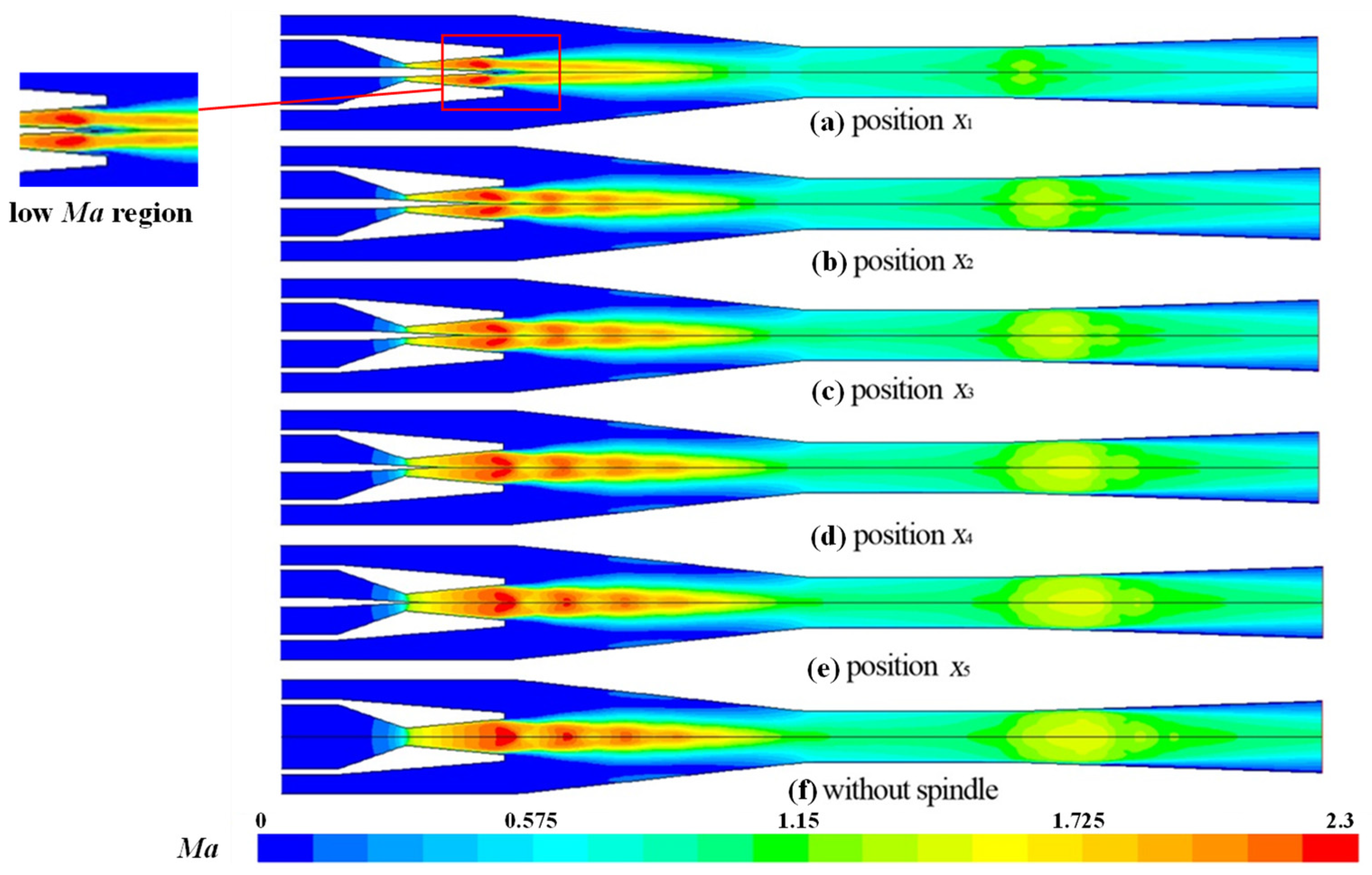
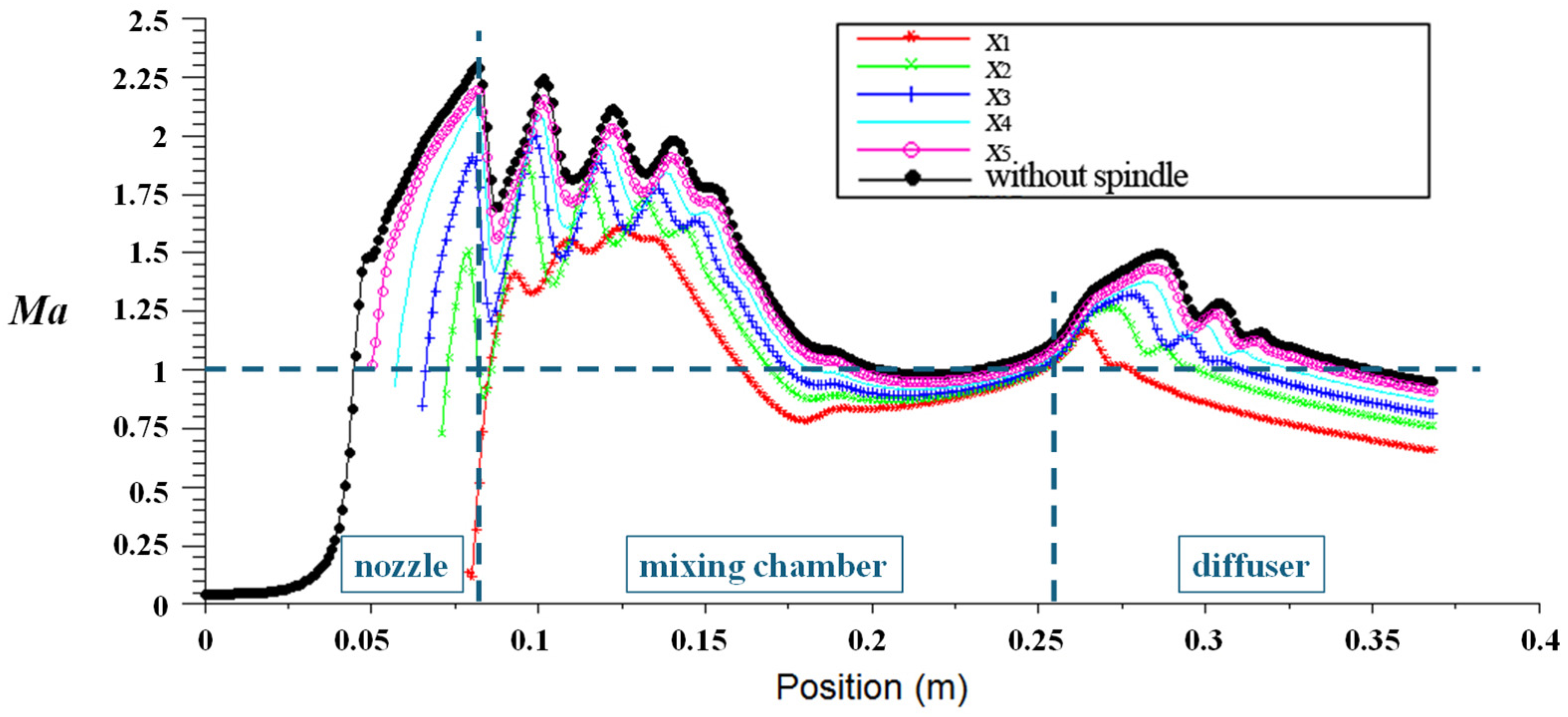
The Ma contours of the steam ejector and the corresponding axial Ma distributions at various spindle positions are illustrated in Figure 20 and Figure 21.
Figure 20 illustrates the complete motive-fluid evolution from acceleration in the nozzle to deceleration in the diffuser, highlighting the decisive effect of spindle position adjustment on the velocity distribution of the flow field and the jet core length. After the high-pressure motive fluid passes through the Laval nozzle, the converging–diverging nozzle structure converts pressure energy into kinetic energy, causing the flow velocity to increase sharply and reach the supersonic regime. Unlike fixed steam ejectors, the spindle located at the throat center causes the motive fluid to form an annular supersonic jet at the nozzle outlet. Consequently, the flow field contains an outer shear layer in contact with the suction fluid and an inner shear layer adjacent to the low-velocity region behind the spindle tail. As the spindle position changes, dt varies accordingly, resulting in different degrees of effective motive-fluid expansion. Accordingly, the motive-fluid Ma at the nozzle outlet varies significantly, with a maximum difference of 74.9% (as illustrated in Figure 21). When the suction fluid is entrained into the suction chamber and interacts with the high-speed motive fluid, a diamond-shaped shock train forms. This shock train causes the fluid velocity to undergo several abrupt changes: the velocity decreases after passing through a compression shock wave and increases after passing through an expansion wave. Notably, a distinct region of low Ma appears under the x1 condition at the spindle tail. This phenomenon is caused by boundary layer separation when the motive fluid flows past the spindle tail, forming a small wake region behind it and resulting in a sharp drop in local flow velocity. Meanwhile, the fluid velocity near the symmetry axis is significantly higher than that farther from the axis in the contraction section of the mixing chamber. The velocity gradient drives the formation of a shear mixing layer between the motive and suction fluids. As the fluid moves downstream, the velocity gradient gradually decreases, indicating the progressive expansion of the shear mixing layer. After entering the constant section of the mixing chamber, full momentum exchange between the two streams promotes velocity uniformity and further accelerates the mixed fluid to a supersonic state. The continuous velocity increase is primarily attributed to the intense momentum transfer between the fluids. The supersonic motive fluid continuously imparts kinetic energy to the low-speed suction fluid through viscous shear. The acceleration effect on the suction fluid significantly outweighs the deceleration caused by the frictional resistance of the spindle wall, thereby driving the suction fluid to accelerate and enabling the mixed fluid to achieve a uniform supersonic state at the end of the constant section. Subsequently, the mixed fluid enters the diffuser, where it encounters a second series of shock trains. During this process, kinetic energy is gradually converted into pressure potential energy, resulting in a continuous decrease in flow velocity. By the time the fluid reaches the ejector outlet, the velocity has decelerated to subsonic levels.
The decisive influence of the spindle position on the length of the supersonic jet core region is demonstrated by Figure 20. As the spindle moves from x1 to x5 along the negative x-axis direction, dt increases continuously. Meanwhile, the high Ma region at the nozzle outlet extends axially and widens radially. This process indicates that a larger throat flow area allows the motive fluid to possess greater momentum, enabling the supersonic flow to be sustained deeper into the constant section of the mixing chamber. Conversely, the combined effects of strong throttling and the expansion of the spindle’s wake region restrict the supersonic motive fluid’s ability to continuously accelerate the downstream fluid. As a result, the jet core region becomes shorter, and the mixed fluid decelerates to subsonic velocity within the contraction section of the mixing chamber, as observed in the x1 case.
The effect of spindle position on the Ma distribution is quantified in Figure 21. When the spindle moves from the design point x3 to x1 along the positive x-axis direction, dt gradually decreases from 5.66 mm to 5 mm (an 11.7% reduction). Consequently, the motive-fluid momentum is weakened, leading to the following changes in the Ma field characteristics: Firstly, the shock wave position in the contraction section of the mixing chamber shifts in the negative x-axis direction, and the shock wave intensity is significantly weakened. Secondly, the global maximum Ma in the ejector, which occurs in the contraction section of the mixing chamber, decreases from 2.0 to 1.6 (a 20% reduction). Moreover, the location where the mixed fluid reaches the supersonic state moves in the positive x-axis direction in the constant section of the mixing chamber, reflecting the reduced capability of the low-energy motive fluid to accelerate the suction fluid. Finally, in the diffuser, the shock wave intensity weakens as dt decreases, accompanied by a reduction in the number of shock waves and an upstream shift in their positions. Correspondingly, the maximum Ma in the diffuser decreases from 1.3 to 1.15 (an 11.5% reduction). Conversely, when the spindle moves from the design point x3 in the negative x-axis direction and is eventually removed from the ejector (corresponding to the condition without a spindle), dt gradually increases from 5.66 mm to 6 mm (a 6% increase). The increase in Gm results in the opposite trend in the Ma field: the global maximum Ma in the ejector increases from 2.0 to 2.3 (a 15% increase), and the maximum Ma in the diffuser increases from 1.3 to 1.5 (a 15.4% increase). The enhanced motive-fluid energy significantly strengthens the shock wave intensity and shifts the shock location downstream in the flow field.
The above results demonstrate that the spindle adjusts the kinetic energy distribution and the jet core length inside the ejector by changing dt. A smaller throat area limits the maximum flow velocity and shock wave intensity, reducing flow losses and making the ejector better adapted to operating conditions with low Pd, high Pm, or high Ps. Conversely, a larger throat area produces higher Ma and stronger shock structures, thereby providing greater resistance to Pd and raising the critical Pd, which enables the ejector to adapt to high Pd, low Pm, or low Ps conditions. The above conclusions clarify the coupling regulation mechanism between the performance and flow field of the adjustable steam ejector from a mechanistic perspective. This analysis further reveals the reasons for the performance differences under the variable operating conditions discussed in Section 3.

4.3. Evolution Mechanism of the Temperature Field

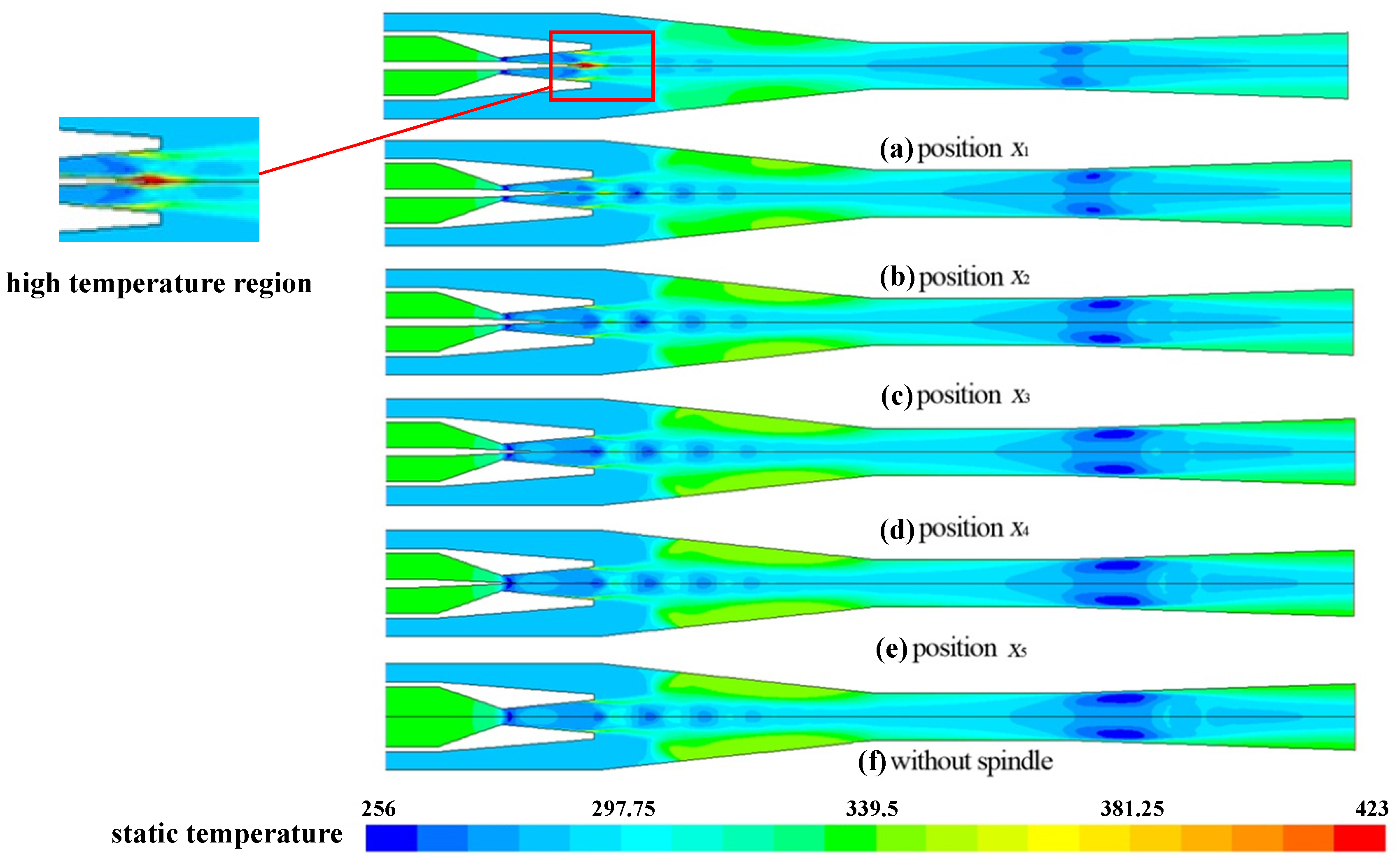
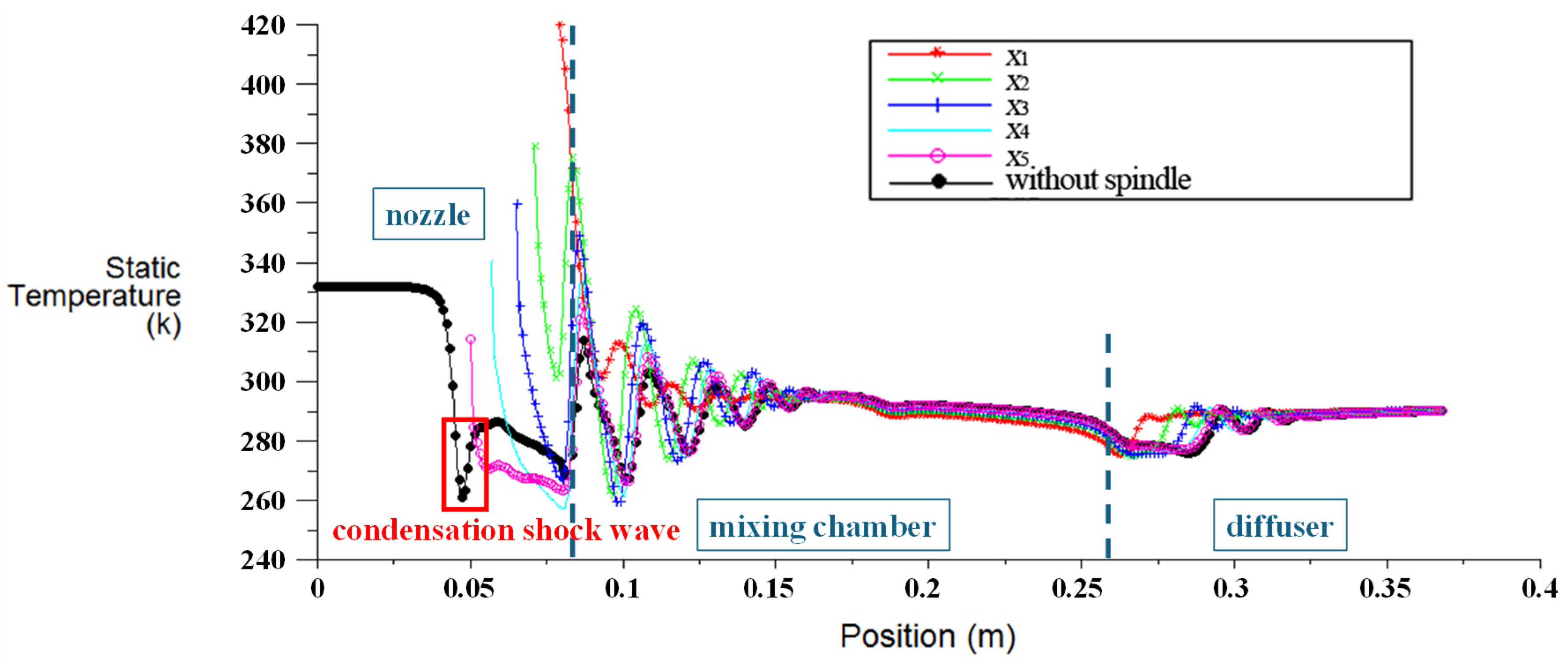
The static temperature contours of the steam ejector and the corresponding axial static temperature distributions at various spindle positions are illustrated in Figure 22 and Figure 23.
Figure 22 and Figure 23 illustrate the thermodynamic state evolution of steam in transonic flow, the thermal effects induced by the condensation shock wave, and the mechanism by which the spindle position influences the temperature distribution within the flow field. Upon entering the nozzle at an initial temperature of 332 K, the motive fluid expands rapidly as the pressure decreases, causing its saturation temperature to decrease correspondingly. Due to the rapid transonic expansion of steam in the nozzle, the steam enters a highly supercooled state within an extremely short period and triggers non-equilibrium condensation. Under conditions of intense non-equilibrium condensation, the substantial release of latent heat of condensation can induce an abrupt rise in fluid temperature, forming a condensation shock wave. Under the condition without the spindle, a sharp temperature rise near the nozzle at x = 50 mm is observed as a direct manifestation of the condensation shock wave, as illustrated in Figure 23. However, for the adjustable steam ejector, the presence of the spindle significantly weakens the non-equilibrium condensation and hinders the formation of the condensation shock wave. The presence of the spindle at the throat center restricts the fluid to a narrow annular channel, thereby substantially increasing the fluid-wall contact area. The enhanced viscous dissipation and frictional heat generation largely offset the expansion-induced cooling effect, thereby restricting the increase in steam supercooling. Consequently, the intense non-equilibrium condensation that would otherwise occur in the central flow channel is significantly suppressed. Unlike the condition without the spindle, the temperature curve does not exhibit a condensation shock wave. Instead, it demonstrates a smoother and more continuous variation rather than an abrupt jump. As the flow continues through the nozzle’s divergent section, the released latent heat is gradually carried away by the high-speed fluid. With continued expansion, the fluid temperature decreases again. At position x1 in Figure 22, a pronounced local high-temperature core appears in the tail region of the spindle, corresponding to the Ma distribution at the same position in Figure 20. This phenomenon is attributed to the stagnation of the high-speed fluid in the wake region behind the spindle tail. In this region, a substantial amount of kinetic energy is instantaneously converted into internal energy, causing the static temperature in this area to rise sharply and approach the total temperature of the motive fluid. The suction fluid at a temperature of 289 K is entrained into the suction chamber and enters the mixing chamber together with the motive fluid. In the contraction section of the mixing chamber, the fluid undergoes a series of diamond-shaped shock trains composed of expansion and shock waves. The fluid temperature decreases across expansion waves and increases significantly across shock waves, resulting in step-like oscillations in the axial temperature distribution. Meanwhile, the region near the axis is dominated by the high-speed, low-temperature motive fluid, exhibiting a significantly lower temperature than the peripheral fluid. As the shear mixing layer between the motive and suction fluids thickens, intense mass and energy exchange occurs between the two fluids, resulting in a gradual reduction in the radial temperature difference along the flow direction. In the near-wall region, the interaction between shock waves and the boundary layer generates a strong adverse pressure gradient, leading to boundary layer separation and inducing local backflow. The intense viscous dissipation in the separation region converts mechanical energy into thermal energy, resulting in a pronounced temperature rise in the backflow region. Within the constant section of the mixing chamber, the temperature field gradually becomes more uniform, and the temperature slowly decreases as the two fluid streams are progressively mixed. Finally, the mixed fluid enters the diffuser. After further compression by the second series of shock waves and the subsonic flow expansion, a portion of the kinetic energy is converted into thermal energy, causing the temperature to slowly rise to the outlet temperature.
As illustrated in Figure 22, when the spindle moves from x1 to x5 in the negative x-axis direction, dt increases continuously. Meanwhile, the low-temperature core region at the nozzle outlet undergoes significant axial elongation. This process indicates that, with a larger throat flow area, sufficient expansion enables the steam to sustain a deeper supercooled state. Conversely, the low-temperature core region is severely constrained by the geometric boundary, exhibiting a highly contracted and discontinuous distribution while being effectively blocked by the high-temperature wake region behind the spindle tail. This phenomenon indicates that, under a small throat flow area, the wake stagnation effect and viscous dissipation are intensified. Consequently, kinetic energy is more rapidly converted into internal energy, causing the fluid temperature to rise quickly along the flow direction.
The effect of the spindle position on the temperature field is quantified in Figure 23. When the spindle moves from the initial position x3 to x1 along the positive x-axis direction, dt decreases by 11.7%. The reduced motive-fluid momentum shifts the shock train in the negative x-axis direction, while both the intensity and number of shock and expansion waves experienced by the mixed fluid in the diffuser decrease. Moreover, the backflow near the wall of the contraction section in the mixing chamber is suppressed, and the heat generated by viscous dissipation is reduced, resulting in a significantly smaller temperature rise in the backflow region. The fluid temperature approaches the final outlet temperature more gradually, and the position where this value is reached shifts upstream (by about 2.3%). In contrast, when the spindle moves from the design point x3 along the negative x-axis direction and is eventually completely removed from the ejector, corresponding to the condition without the spindle, dt increases by 6%. Meanwhile, the increased motive-fluid energy causes the opposite trend in the temperature field: the intensity and number of shock waves increase, the shock wave position shifts downstream by about 2.4%, and the temperature rise in the backflow region becomes more pronounced.
Overall, by changing dt, the spindle controls the thermodynamic behavior and phase-transition process inside the ejector. A smaller throat area suppresses the sharp temperature rise caused by backflow in the contraction section of the mixing chamber, thereby reducing irreversible heat loss and making the ejector suitable for operating conditions with low Pd, high Pm, or high Ps. Conversely, a larger throat area strengthens the shock wave effect, thereby promoting more thorough mixing and mass–energy exchange between the motive fluid and the suction fluid, making the ejector suitable for high Pd, low Pm, or low Ps conditions. These results further clarify the fundamental reason for the different performance responses of the adjustable steam ejector under variable operating conditions.

4.4. Evolution Mechanism of β

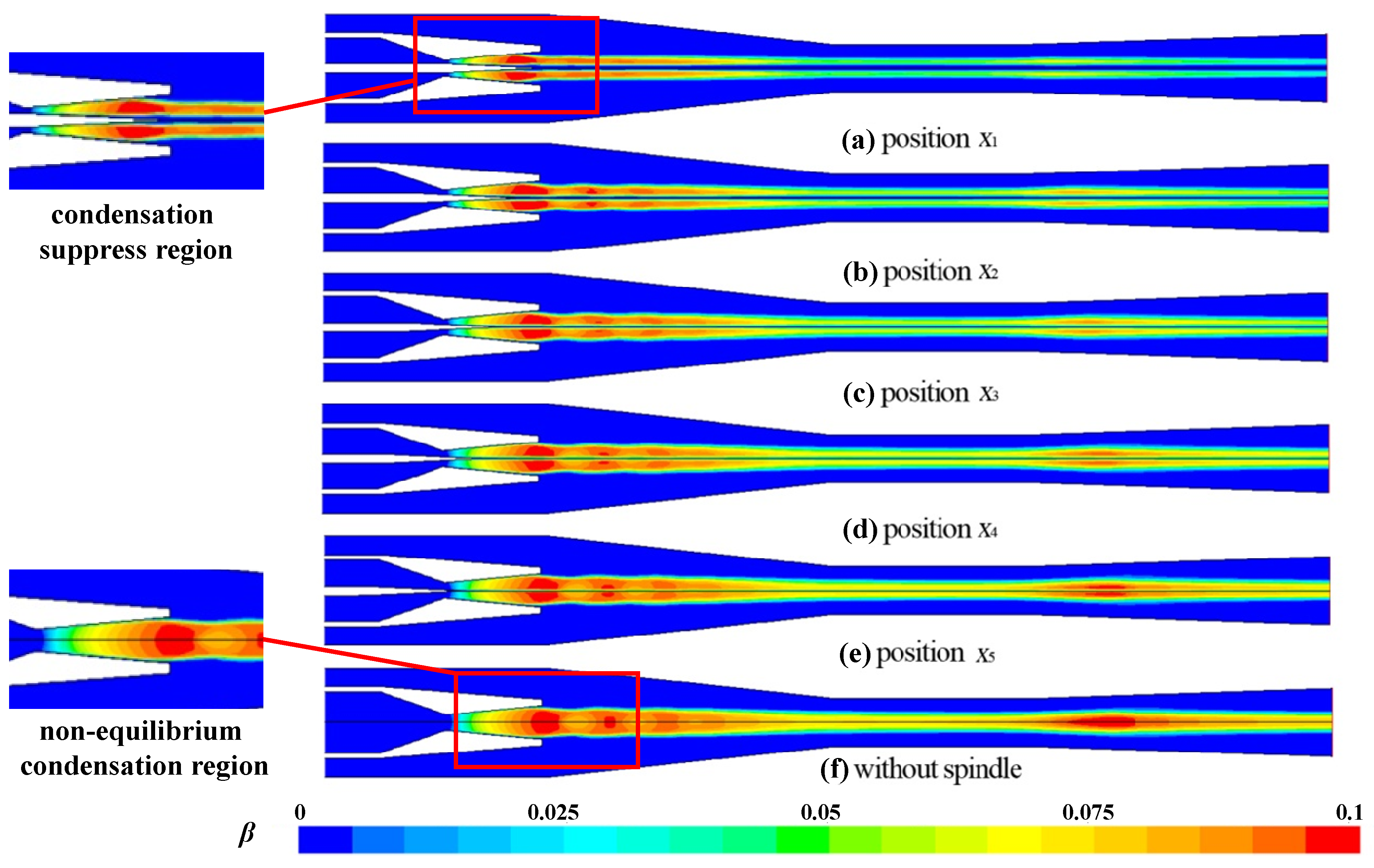
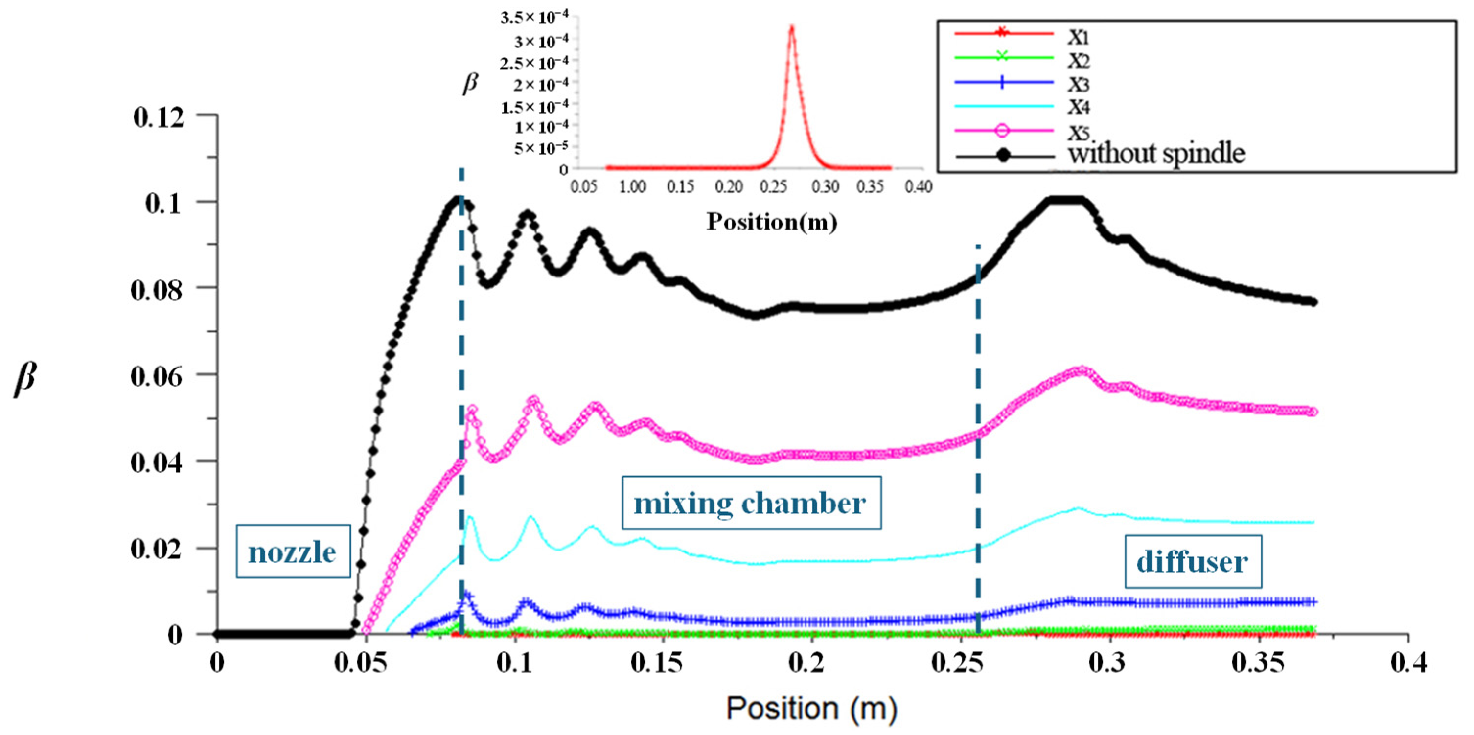
The β contours of the steam ejector and the corresponding axial β distributions at various spindle positions are illustrated in Figure 24 and Figure 25.
Significant spatial heterogeneity in the distribution of β within the ejector is illustrated by Figure 24. Non-equilibrium condensation primarily occurs near the axis, whereas β is pronouncedly lower farther from the axis. Owing to the most intense expansion and the lowest temperature of the axial fluid (Figure 22), the critical supercooling for condensation is reached first in this region. Meanwhile, heat transfer from the suction fluid and viscous dissipation within the boundary layer increase the near-wall temperature, resulting in a relatively higher fluid temperature that inhibits the nucleation and growth of droplets. The two series of shock trains in the mixing chamber and diffuser cause abrupt temperature changes, leading to fluctuations in β. As shown in Figure 25, moving the spindle from the design point x3 to x1 along the positive x-axis direction decreases dt by 11.7%. The overall temperature rise in the flow field significantly reduces β, and the maximum β decreases markedly by about 57.7%. At position x1, the pronounced local high-temperature core at the spindle tail (Figure 22) prevents non-equilibrium condensation in the mixing chamber (explicitly labeled as the condensation-suppressed region in Figure 24), resulting in β = 0. Prior to the appearance of the second series of shock trains in the diffuser, the supercooling degree increases, and non-equilibrium condensation occurs in the flow field (Figure 25). Conversely, when the spindle moves from the design point x3 in the negative x-axis direction and is completely removed (corresponding to the condition without the spindle), dt increases by 6%. This change leads to the formation of a pronounced non-equilibrium condensation region near the nozzle outlet (as highlighted in Figure 24), and β reaches a global maximum of 0.1.
Overall, analyzing the flow–thermal–phase-change coupling mechanism reveals that liquid phase generation and evolution are essentially the macroscopic manifestation of the competition between expansion-induced cooling and viscous dissipation heating in the flow field. In supersonic flow, the sharp pressure decrease serves as the primary driving force and enables the fluid to acquire extremely high kinetic energy in the velocity field. Governed by energy conservation, this acceleration process consumes the internal energy of the fluid and causes the static temperature to fall below the saturation line, thereby generating the requisite supercooling for non-equilibrium condensation. From multiple perspectives, the interactions among shock wave structures, condensation effects, and entrainment performance are complex and interdependent. The latent heat released by condensation effects acts as a thermodynamic source that modifies the local pressure distribution, thereby shifting the position and strength of the shock wave structures. These altered shock waves, in turn, redefine the velocity gradients and turbulent shear stresses at the interface, which fundamentally govern the momentum transfer efficiency and the entrainment performance. However, the flow channel confinement induced by spindle movement changes the previously described energy-conversion path: the extremely high velocity gradient in the narrow annular flow channel induces an intense shear effect, partially converting kinetic energy back into internal energy. This thermal effect, resulting from velocity field distortion, directly weakens the low-temperature environment established by the pressure field, thereby diminishing or even preventing the non-equilibrium condensation. It can be reasonably inferred from an engineering perspective that such a high-dryness flow field can significantly reduce the risk of erosion caused by high-speed droplets on the ejector wall. Consequently, this protective effect offers potentially important value in improving equipment operational reliability and extending service life. Based on the above analyses of the coupling mechanisms, the regulation strategies and their corresponding multi-field effects under variable operating conditions are systematically summarized in Table 5.

5. Conclusions

Adjustable steam ejectors effectively address the challenge of rapid performance decline under variable operating conditions. Furthermore, the complex transonic flow characteristics hold significant theoretical research value. Consequently, adjustable steam ejectors continue to attract extensive scholarly interest. The novelty of this study lies in revealing the performance response of the adjustable steam ejector and the flow–thermal–phase-change coupling mechanism by investigating the regulatory effects of spindle positions on wet-steam non-equilibrium condensation, thereby interpreting the resulting condensation suppression and shock wave dynamics. Considering the non-equilibrium condensation effect, this study quantitatively revealed the influence of different operating conditions and spindle positions on the evolution mechanisms of ejector performance, pressure field, Mach number (Ma) field, temperature field, and condensate mass fraction (β) field. Moreover, the relationship between ejector performance and flow characteristics was investigated. Based on the systematic analysis and discussion above, the following key points are obtained:
(1) The spindle adjusts the steam ejector performance under variable operating conditions by changing the equivalent throat diameter (dt). When the system operates under relatively high motive pressure (Pm), high suction pressure (Ps), or low discharge pressure (Pd), the spindle should be shifted along the positive x-axis direction to increase the entrainment ratio (Er). Conversely, under conditions of relatively low Pm, low Ps, or high Pd, the spindle should be shifted along the negative x-axis direction. In this case, the enhanced motive-fluid momentum flux can be prioritized to ensure greater disturbance resistance and a broader operational range for the system.
(2) The position of the spindle determines the motive-fluid mass flow rate (Gm), which in turn influences the pressure field and Ma field characteristics. Specifically, under a representative operating condition (Pm = 19.8 kPa, Ps = 1.8 kPa, and Pd = 1.9 kPa), when the spindle was moved from the design point x3 along the positive x-axis direction, dt decreased by 11.7%, and Gm decreased by 22.6%. As a result, the distance between shock waves gradually decreased along the flow direction (by about 14.1%), and the global maximum Ma dropped sharply from 2.0 to 1.6 (a 20% reduction). Meanwhile, the maximum Ma in the diffuser decreased from 1.3 to 1.15 (an 11.5% reduction), and the jet core was significantly shortened. Conversely, moving the spindle from the design point x3 along the negative x-axis direction increased dt by 6% and Gm by 11.9%. The enhanced motive-fluid energy extended the distance over which the shock train was maintained in the mixing chamber by 4.2%. The global maximum Ma rose to 2.3 (a 15% increase), and the maximum Ma in the diffuser increased to 1.5 (a 15.4% increase). Additionally, both the intensity and the number of shock and expansion waves experienced by the mixed fluid in the diffuser increased.
(3) Flow–thermal–phase-change coupling analysis reveals that the spindle position regulates the thermodynamic behavior and phase-transition processes within the ejector. For instance, under the selected operating point, moving the spindle in the positive x-axis direction weakened the local backflow near the wall of the contraction section of the mixing chamber and reduced the heat generated by viscous dissipation, resulting in a significant decrease in temperature rise within the backflow area. The fluid temperature approached the outlet temperature more gradually and at an earlier position, while the average temperature of the flow field increased. Meanwhile, β in the mixing chamber was significantly reduced (from 0.1 to 0). As a plausible engineering inference, such a high-dryness flow field can significantly reduce the risk of erosion caused by high-speed droplets on the ejector wall. Consequently, this protective effect offers potentially important value in improving equipment operational reliability and extending service life.
(4) The coupling regulation mechanism between the performance of the adjustable steam ejector and the flow field is revealed. As the spindle reduces dt and consequently the throat area, the maximum flow velocity and shock wave intensity are effectively constrained. This suppression prevents a pronounced temperature rise due to backflow and helps reduce irreversible heat and flow losses, making this configuration suitable for low Pd, high Pm, or high Ps operating conditions. Conversely, increasing the throat area leads to higher Ma and stronger shock waves, thereby enhancing resistance to Pd, raising the critical Pd, and making the system suitable for high Pd, low Pm, or low Ps operating conditions.

Author Contributions

Conceptualization, Y.L., C.G., Y.H., H.H., H.L. and S.S.; Methodology, C.G., Y.H., H.H., H.L. and S.S.; Software, S.S.; Validation, Y.L., C.G., Y.H., H.H. and H.L.; Formal analysis, Y.L., C.G., H.H. and X.L.; Investigation, Y.L., C.G., Y.H., H.H. and X.L.; Resources, Y.L., X.L. and S.S.; Data curation, Y.L. and C.G.; Writing—original draft, Y.L. and C.G.; Writing—review & editing, C.G., Y.H., H.H., X.L. and H.L.; Visualization, C.G. and H.L.; Supervision, Y.L., H.L. and S.S.; Project administration, H.L. and S.S.; Funding acquisition, Y.L., H.L. and S.S. All authors have read and agreed to the published version of the manuscript.

Funding

This research was funded by the Fundamental Research Funds for the Provincial Universities of Liaoning, grant number LJ212410150010. Moreover, it was funded by the Liaoning Province Science and Technology Plan Joint Program Project 2025, grant number 2025-BSLH-092. In addition, it was funded by the Department of Education Fund of Liaoning Province, grant number LJ212510150032.

Data Availability Statement

The original contributions presented in the study are included in the article, further inquiries can be directed to the corresponding author.

Acknowledgments

The authors are grateful for the above-mentioned fundings for their support.

Conflicts of Interest

The authors declare no conflict of interest.

Nomenclature

a[m/s]Sonic velocity
B[m3/kg]Virial coefficients
C[m6/kg2]Virial coefficients
CP[J/(kg∙K)]Isobaric heat capacity
d[m]Diameter
E[J]Total energy
Er[−]Entrainment ratio
e[%]Relative error
F[N/m3]Source term
G[kg/s]Mass flow rate
h[J/kg]Specific enthalpy
hlv[J/(kg)]Latent heat of condensation
J[1/s]Nucleation rate
K[W/(m2∙K)]Heat transfer coefficient
k[m2/s2]Turbulent kinetic energy
kB[−]Boltzmann constant
Ma[−]Mach number
Mm[kg]Molecular mass of water
P[Pa]Pressure
Pd*[Pa]Critical discharge pressure
p[−]Apparent order
qc[−]Coefficient of condensation
R[−]Gas-law constant
r[m]Droplet radius
r21[−]Mesh refinement factor
r32[−]Mesh refinement factor
S[−]Supersaturation ratio
s[J/(kg∙mol∙K)]Specific entropy
ST[kg∙K/(m3∙s)]Viscous dissipative term
T[K]Temperature
∆T[K]Subcooling degree
N-S[−]Navier–Stokes
RANS[−]Reynolds Average Navier–Stokes
v[m/s]Velocity
Vi[m3]The volume of the ith grid
y+[−]Dimensionless distance of nodes in the first layer of the mesh from the wall
Special characters
β[−]Liquid mass fraction
Γ[kg/s]Liquid mass generation rate
ρ[kg/m3]Density
γ[−]Specific heat capacities ratio
μ[Pa/s]Dynamic viscosity
σ[N/m]Liquid surface tension
η[1/m3]Droplet number density
θ[−]Non-isothermal correction factor
φext[−]Extrapolation solution
φ[−]Mesh solution in GCI
ν[m2/s]Kinematic viscosity
ε[m2/s3]Turbulent dissipation rate
τ[N/m2]Stress tensor
Subscripts
sat Saturation
m Motive steam
s Suction steam
tThroat
d Discharge steam
l Liquid
vVapor
max Maximum
* Critical
-Average
effEffective
i,jSpace components

References

  1. Dai, Z.; Xiang, J.; Qin, S.; Zhang, X.; Nawaz, K. Irreversibility distribution and characteristics within an ejector using zeotropic mixtures in the ejector refrigeration system. Int. Commun. Heat Mass Transf. 2026, 172, 110685. [Google Scholar] [CrossRef]
  2. Das, R.K.; Date, A. Sustainable water desalination using eductor and waste heat: A review and suggestion for future research. Desalination 2025, 603, 118687. [Google Scholar] [CrossRef]
  3. Li, Y.; Huang, H.; Liu, S.; Ge, C.; Huang, J.; Shen, S.; Guo, Y.; Yang, Y. Overview of the Energy Conservation and Sustainable Transformation of Aerospace Systems with Advanced Ejector Technology. Energies 2025, 19, 221. [Google Scholar] [CrossRef]
  4. Li, Y.; Huang, H.; Shen, S.; Guo, Y.; Yang, Y.; Liu, S. Application Advances and Prospects of Ejector Technologies in the Field of Rail Transit Driven by Energy Conservation and Energy Transition. Energies 2025, 18, 3951. [Google Scholar] [CrossRef]
  5. Besagni, G. Ejectors on the cutting edge: The past, the present and the perspective. Energy 2019, 170, 998–1003. [Google Scholar] [CrossRef]
  6. Tashtoush, B.; Songa, I.; Morosuk, T. Exergoeconomic analysis of a variable area solar ejector refrigeration system under hot climatic conditions. Energies 2022, 15, 9540. [Google Scholar] [CrossRef]
  7. Yu, M.; Wang, C.; Wang, L.; Wang, X. Flow characteristics of coaxial-nozzle ejector for PEMFC hydrogen recirculation system. Appl. Therm. Eng. 2024, 236, 121541. [Google Scholar] [CrossRef]
  8. Hao, X.; Liu, D.; Gao, N.; Chen, G.; Zhang, L.; Tu, Q. Performance investigation of a novel multi-parameter adjustable ejector with a broad operating range. Int. J. Refrig. 2025, 173, 139–152. [Google Scholar] [CrossRef]
  9. Chen, Z.; Zhao, H.; Kong, F.; Liu, G.; Wang, L.; Lai, Y. Synergistic effect of adjustable ejector structure and operating parameters in solar-driven ejector refrigeration system. Sol. Energy 2023, 250, 295–311. [Google Scholar] [CrossRef]
  10. Zhang, K.; Shen, S.; Yang, Y. Numerical investigation on performance of the adjustable ejector. Int. J. Low-Carbon Technol. 2010, 5, 51–56. [Google Scholar] [CrossRef]
  11. Jiang, X.; Huang, Y.; Jiang, P.; Zhu, Y. Modeling and experimental research on adjustable ejector in fuel cell gas circulation system. Appl. Therm. Eng. 2024, 257, 124431. [Google Scholar] [CrossRef]
  12. Contiero, L.; Banasiak, K.; Verlaat, B.; Hafner, A.; Försterling, S.; Allouche, Y. Thermal design of an ejector-supported cycle using krypton for cooling of particle detector accelerators. Int. J. Refrig. 2025, 178, 160–169. [Google Scholar] [CrossRef]
  13. Yang, Y.; Ren, X.; Li, Y.; Wang, N.; Zhang, K.; Shen, S. Similarity characteristics of qualitative and quantitative regulation for adjustable ejector. Int. J. Low-Carbon Technol. 2023, 18, 423–432. [Google Scholar] [CrossRef]
  14. Jing, H.; Yuan, Z.; Gao, J.; Chen, W.; Chong, D. Prediction of adjustable steam ejectors performance through Integration of numerical simulation and theoretical model. Appl. Therm. Eng. 2025, 267, 125841. [Google Scholar] [CrossRef]
  15. Chen, B.; Chen, H.; Xu, Z.; Liang, W.; Huang, H.; Xia, L. Performance and Economic Analysis of a High-Efficiency Wide-Working Load Distillation System with Combined Ejector. Processes 2025, 13, 3783. [Google Scholar] [CrossRef]
  16. Dolgun, E.C.; Dolgun, G.K.; Aktaş, M. Improving a steam TVR: Insights from variable ejector geometry and CFD simulations. Therm. Sci. Eng. Prog. 2025, 69, 104439. [Google Scholar] [CrossRef]
  17. Abbady, K.; Al-Mutawa, N.; Almutairi, A. The performance analysis of a variable geometry ejector utilizing CFD and artificial neural network. Energy Convers. Manag. 2023, 291, 117318. [Google Scholar] [CrossRef]
  18. Ren, J.; Zhao, H.; Wang, M.; Miao, C.; Wu, Y.; Li, Q. Design and investigation of a dynamic auto-adjusting ejector for the MED-TVC desalination system driven by solar energy. Entropy 2022, 24, 1815. [Google Scholar] [CrossRef] [PubMed]
  19. Besagni, G.; Cristiani, N. Multi-scale evaluation of an R290 variable geometry ejector. Appl. Therm. Eng. 2021, 188, 116612. [Google Scholar] [CrossRef]
  20. Rand, C.P.; Croquer, S.; Poirier, M.; Poncet, S. Modulation of a R245fa Supersonic Ejector By A Movable Needle: A Numerical Study. In Proceedings of the 2nd International Conference on Fluid Flow and Thermal Science (ICFFTS’21), Virtual Conference, 24–26 November 2021. [Google Scholar]
  21. Zhang, Y.; Yan, L.; Zhang, J.; Ma, S.; Guo, W. Analysis of Off-Design Performance and Thermal–Fluid–Structural Coupling Characteristics of an Adjustable Air Ejector. Materials 2026, 19, 294. [Google Scholar] [CrossRef] [PubMed]
  22. Guo, Y.; Zhang, J.; Ma, S.; Zhang, J. Coupling optimization design of adjustable nozzle for a steam ejector. Appl. Therm. Eng. 2024, 252, 123550. [Google Scholar] [CrossRef]
  23. Chen, Y.-M.; Sun, C.-Y. Experimental study of the performance characteristics of a steam-ejector refrigeration system. Exp. Therm. Fluid Sci. 1997, 15, 384–394. [Google Scholar] [CrossRef]
  24. Wang, X.; Sun, H.; Sun, H. Numerical Simulation of Influence of Nozzle Spindle Position on the Performance of Steam Ejector. J. Northeast. Univ. (Nat. Sci.) 2020, 41, 706. [Google Scholar]
  25. Young, B.J. An equation of state for steam for turbomachinery and other flow calculations. J. Eng. Gas Turbines Power 1988, 110, 1–7. [Google Scholar] [CrossRef]
  26. IAPWS-IF97; Revised Release on the IAPWS Industrial Formulation 1997 for the Thermodynamic Properties of Water and Steam. The International Association for the Properties of Water and Steam: Lucerne, Switzerland, 2007.
  27. Li, Y.; Shen, S.; Niu, C.; Mu, X.; Zhang, L. The effect of variable motive pressures on the performance and shock waves in a supersonic steam ejector with non-equilibrium condensing. Int. J. Therm. Sci. 2023, 185, 108034. [Google Scholar] [CrossRef]
  28. Kong, N.; Qi, Z. Influence of speed of sound in two-phase region on 1-D ejector performance modelling. Appl. Therm. Eng. 2018, 139, 352–355. [Google Scholar] [CrossRef]
  29. Giacomelli, F.; Biferi, G.; Mazzelli, F.; Milazzo, A. CFD Modeling of the Supersonic Condensation Inside a Steam Ejector. Energy Procedia 2016, 101, 1224–1231. [Google Scholar] [CrossRef]
  30. Li, Y.; Shen, S.; Yang, Y. Three-dimensional characteristics of aerodynamic shockwave and condensation shockwave in steam ejectors. Desalination 2024, 581, 117606. [Google Scholar] [CrossRef]
  31. Daiguji, H.; Ishazaki, K.; Ikohagi, T. A high-resolution numerical method for transonic non-equilibrium condensation flows through a steam turbine cascade. Proc. 6th Int. Symp. Comput. Fluid Dyn. 1995, 1, 479–484. [Google Scholar]
  32. Shigeki, S.; Yoshio, S. Two-dimensional analysis for non-equilibrium homogeneously condensing flows through steam turbine cascade. JSME Int. J. Fluids Therm. Eng. 2002, 45, 865–871. [Google Scholar]
  33. Li, Y.; Niu, C.; Shen, S.; Mu, X.; Zhang, L. Turbulence model comparative study for complex phenomena in supersonic steam ejectors with double choking mode. Entropy 2022, 24, 1215. [Google Scholar] [CrossRef] [PubMed]
  34. Moore, M.J.; Walters, P.T.; Crane, R.I.; Davidson, B.J. Predicting the fog-drop size in wet-steam turbines. In Proceedings of the IMechE Conference on Heat and Fluid Flow in Steam and Gas Turbine Plant, Coventry, UK, 3–5 April 1973. C37/73. [Google Scholar]
  35. Masoud, A.; Mohsen, M.; Domenico, F.; Massimo, S. Variable Geometry Ejectors: A Systematic Review of Modulation Mechanisms, Actuation Strategies, Modeling Approaches, and Applications. Energies 2026, 19, 1350. [Google Scholar] [CrossRef]
  36. Varga, S.; Oliveira, A.C.; Ma, X.; Omer, S.A.; Zhang, W.; Riffat, S.B. Experimental and numerical analysis of a variable area ratio steam ejector. Int. J. Refrig. 2011, 34, 1668–1675. [Google Scholar] [CrossRef]
Figure 1. Schematic view of the ejector [23].
Energies 19 03186 g001
Figure 2. Schematic diagram of the spindle in the adjustable nozzle.
Energies 19 03186 g002
Figure 3. 2D grid diagram of the adjustable steam ejector.
Energies 19 03186 g003
Figure 4. Verification of grid independence. (a). Static pressure distribution of the axis. (b) Axial-wall shear stress distribution of the ejector wall.
Energies 19 03186 g004aEnergies 19 03186 g004b
Figure 5. Model verification. (a) Comparison of axial static pressure ratio. (b) β predicted by the non-equilibrium condensation model.
Energies 19 03186 g005
Figure 6. Variations in Er with Pd.
Energies 19 03186 g006
Figure 7. Variations in Gs with Pd.
Energies 19 03186 g007
Figure 8. Variations in Gm with Pd.
Energies 19 03186 g008
Figure 9. Variations in Gd with Pd.
Energies 19 03186 g009
Figure 10. Variations in Er with Pm.
Energies 19 03186 g010
Figure 11. Variations in Gs with Pm.
Energies 19 03186 g011
Figure 12. Variations in Gm with Pm.
Energies 19 03186 g012
Figure 13. Variations in Gd with Pm.
Energies 19 03186 g013
Figure 14. Variations in Er with Ps.
Energies 19 03186 g014
Figure 15. Variations in Gs with Ps.
Energies 19 03186 g015
Figure 16. Variations in Gm with Ps.
Energies 19 03186 g016
Figure 17. Variations in Gd with Ps.
Energies 19 03186 g017
Figure 18. Static pressure distribution of the steam ejector at different spindle positions.
Energies 19 03186 g018
Figure 19. Axial static pressure distribution of the steam ejector at different spindle positions.
Energies 19 03186 g019
Figure 20. Ma distribution of the steam ejector at different spindle positions.
Energies 19 03186 g020
Figure 21. Axial Ma distribution of the steam ejector at different spindle positions.
Energies 19 03186 g021
Figure 22. Static temperature distribution of the steam ejector at different spindle positions.
Energies 19 03186 g022
Figure 23. Axial static temperature distribution of the steam ejector at different spindle positions.
Energies 19 03186 g023
Figure 24. β distribution of the steam ejector at different spindle positions.
Energies 19 03186 g024
Figure 25. Axial β distribution of the steam ejector at different spindle positions.
Energies 19 03186 g025
Table 1. Operating conditions of the simulation.
Pm (kPa)Tm (K)Ps (kPa)Ts (K)Pd (kPa)
Group 119.8335.01.8289.01.9~2.9
Group 25.0~27.0308.0~341.81.8289.01.9
Group 319.8335.01.6~2.6287.2~294.91.9
Table 2. Spindle positions and dt.
Spindle Position x (mm)dt (mm)
x1 = 145.00
x2 = 75.37
x3 = 05.66
x4 = −75.85
x5 = −145.96
without spindle6.00
Table 3. Calculated results of the GCI method.
peext (%)e21 (%) G C I fine 21 (%) G C I fine 32 (%)
Average7.645.977 × 10−30.0787.478 × 10−30.104
Max16.810.3730.3240.4680.459
Min0.471.547 × 10−75.403 × 10−41.933 × 10−76.779 × 10⁻⁴
Table 4. Comparison of the Er.
Pm (torr)Ps (torr)Simulated ErExperimental ErError
89.39.80.370.382.8%
89.07.50.240.267.6%
89.313.60.500.511.0%
146.813.60.320.346.0%
116.013.60.400.401.1%
186.313.60.240.253.4%
Table 5. Regulation strategies and corresponding multi-field effects under variable operating conditions.
Operating ConditionsRecommended Spindle Direction (Change in dt)Effect on GmEffect on ErEffect on Shock Wave IntensityEffect on β
high Pmpositive x-axis direction (decrease dt)decreaseincrease Erweakensuppress
low Pmnegative x-axis direction (increase dt)increasewiden critical rangestrengthenpromote
high Pspositive x-axis direction (decrease dt)decreaseincrease Erweakensuppress
low Psnegative x-axis direction (increase dt)increasewiden critical rangestrengthenpromote
high Pdnegative x-axis direction (increase dt)increasewiden critical rangestrengthenpromote
low Pdpositive x-axis direction (decrease dt)decreaseincrease Erweakensuppress
Disclaimer/Publisher’s Note: The statements, opinions and data contained in all publications are solely those of the individual author(s) and contributor(s) and not of MDPI and/or the editor(s). MDPI and/or the editor(s) disclaim responsibility for any injury to people or property resulting from any ideas, methods, instructions or products referred to in the content.