Article

Study on the Heat Release Behaviors During Oxidation of Pulverized Coal-Dispersed Ventilation Air Methane in Regenerator Channels

1
School of Resources and Safety Engineering, Chongqing University, Chongqing 400044, China
2
State Key Laboratory of Coal Mine Disaster Prevention and Control, Chongqing 400037, China
3
China Coal Technology and Engineering Group Chongqing Research Institute, Chongqing 400037, China
4
School of Energy and Power Engineering, Chongqing University, Chongqing 400044, China
*
Authors to whom correspondence should be addressed.
Energies 2026, 19(11), 2600; https://doi.org/10.3390/en19112600
Submission received: 18 April 2026 / Revised: 15 May 2026 / Accepted: 24 May 2026 / Published: 28 May 2026
(This article belongs to the Section I2: Energy and Combustion Science)

Abstract

As a low-grade energy source, ventilation air methane (VAM) can be utilized via regenerative oxidation technology. However, its low methane concentration hinders self-sustained operation in regenerators. Blending pulverized coal provides a feasible approach to supplement heat input and offers a potential route for improving energy utilization and reducing methane emissions from coal mines. This study numerically investigated the heat release behaviors during the oxidation of pulverized coal-dispersed VAM in a 400 mm-long millimeter-scale regenerator channel, with particular attention to the complementary heat-release roles of methane and pulverized coal. The results show that when the wall temperature for methane oxidation increases from 1173 K to 1373 K, the methane oxidation rate rises from 3.72 mol·m−3·s−1 to 23.87 mol·m−3·s−1—an enhancement by a factor of 5.3. For pulverized coal, inlet velocity and coal feed rate governed the completeness of pulverized coal combustion and the volatile reaction rate, respectively. Among the four tested coal–methane heat input ratios (4:1, 3:2, 2:3, 1:4), the 4:1 case showed the most favorable burnout behavior. Further analysis of a representative 2:3 co-combustion case revealed a complementary heat-release pattern: methane provided rapid upstream heat release, whereas pulverized coal sustained the downstream high-temperature region and mitigated the temperature decay after methane consumption.

1. Introduction

Methane is a potent greenhouse gas with a 100-year global warming potential approximately 28 times that of carbon dioxide, and its large-scale emissions have imposed increasingly serious impacts on the climate system [1,2]. Among various emission sources, VAM from coal mines is prominent in the energy sector—it accounts for approximately 64% of methane emissions from underground coal mines, with concentrations typically ranging from 0.1% to 1% [3,4]. Large-scale emissions of such low-concentration VAM not only exacerbate the greenhouse effect but also waste high-quality clean energy. To address this issue, academia and industry have conducted extensive research on VAM oxidation, establishing a mainstream technology system centered on regenerative oxidation. This system provides a feasible pathway for the recovery and utilization of low-concentration VAM.
For VAM utilization as the primary fuel, the core technology relies on Thermal Flow Reversal Reactors (TFRRs)—the backbone of current VAM resource utilization systems [5]. TFRRs operate by periodically switching gas flow direction, allowing VAM to absorb heat, warm up, and oxidize in the regenerative medium for self-sustained combustion. These reactors promote methane oxidation via heat transfer from regenerative materials and allow the recovery of heat generated by oxidation. For example, Shi et al. [6] found that embedding heat exchange tubes in the high-temperature zone of TFRR regenerative oxidizers enables stable heat recovery, with a maximum efficiency of 61.72%. Nevertheless, existing TFRR-based technology has a key limitation: ultra-low-concentration VAM (≤0.5%) cannot maintain self-sustained oxidation due to low heat release. The traditional solution—blending high-concentration methane to increase VAM concentration—is hard to promote in coal mines lacking high-concentration extracted methane sources, leading to direct venting of large quantities of low-concentration VAM [7,8]. To tackle this, a novel approach is proposed: supplementing the oxidation system with pulverized coal. By leveraging the abundant and easily accessible pulverized coal from coal mines, blending it with low-concentration VAM allows the heat released from pulverized coal combustion to support the self-sustained oxidation of VAM. This not only alleviates the shortage of high-concentration methane but also realizes on-site resource recycling, thereby reducing both environmental pollution and energy waste.
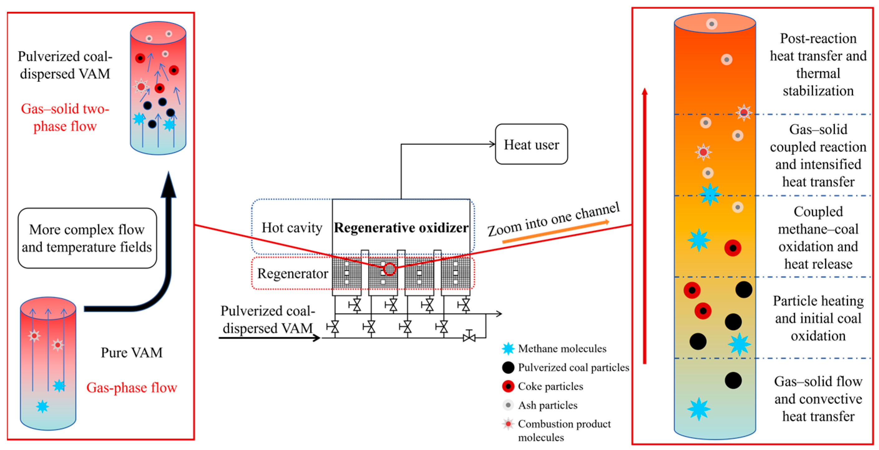
To advance the industrial application of this technology, it is first necessary to clarify the heat transfer and heat release behaviors during oxidation of the gas–solid two-phase flow of pulverized coal-dispersed VAM in millimeter-scale regenerator channels, as schematically illustrated in Figure 1. This process differs significantly from the regenerative oxidation of pure VAM, as it involves not only the coupling of gas–solid two-phase flow fields, concentration fields, and temperature fields but also the coupled effects of heat transfer and oxidation of the gas–solid fuel mixture—its complexity far exceeds that of the oxidation of a single gaseous fuel. Several studies have examined aspects relevant to gas–solid fuel mixtures’ oxidation. Zhang et al. [9] investigated the mitigation of ventilation air methane and energy recovery in a site-trial thermal flow-reversal reactor and discussed the effects of inlet gas flow rate, methane concentration fluctuation, channel size, and energy recovery on reactor behavior. Li et al. [10] examined the autoignition characteristics of methane/coal-particle/air mixtures under heated conditions and showed that the interaction between methane and solid particles can significantly affect the ignition behavior of mixed-fuel systems. In addition, Rahman et al. [11] studied the three-dimensional rotating flow heat transfer of particle–fluid suspensions above a flat surface and found that particles have a negligible effect on the temperature field when the Prandtl number ranges from 0.5 to 7.0. Wang et al. [12] employed a CFD-DEM coupled heat transfer method for isolated particles, revealing that the fluid velocity and particle diameter have a more significant impact on convective heat transfer than on thermal conduction, with particle–fluid convection dominating. Patro et al. [13] used a two-fluid model to study gas–solid heat transfer in adiabatic horizontal pipes, noting that increases in the particle diameter and inlet velocity reduce gas–solid heat transfer efficiency. In addition, Taofeeq et al., Li et al., Bisognin et al., and Uwitonze et al. investigated the effects of tube bundles, inlet velocity, particle parameters, and flow dynamics on heat transfer, respectively [14,15,16,17].
However, current studies on pulverized coal-dispersed VAM in millimeter-scale regenerator channels remain limited, especially regarding the axial heat-release behaviors and interaction mechanisms of the gas–solid dual fuel during oxidation. As a result, the parameter sensitivities and complementary roles of methane and pulverized coal in regenerative channels have not yet been clearly understood. To address this gap, the present study numerically investigates the oxidation and heat-release behaviors of methane, pulverized coal, and their mixtures under different operating parameters (such as inlet velocity, wall temperature) and coal–methane heat input ratios. The aim is to clarify the heat-release characteristics, identify the dominant influencing parameters, and provide a channel-scale basis for the design and optimization of regenerative oxidation systems for ultra-lean VAM.

2. Numerical Simulation Methods

2.1. Model Construction Methods

To investigate the heat release behaviors of pulverized coal-dispersed VAM in regenerators, provide a basis for optimizing the structural parameters of regenerators adapted to gas–solid two-phase flow and dual-fuel heat release, and lay a research foundation for the industrial utilization of such VAM, this study employed computational fluid dynamics (CFD) software ANSYS Fluent 2022 R2 to perform numerical simulations of the system’s flow, heat transfer, and heat release processes. A millimeter-scale regenerator channel model was established, featuring a length of 400 mm, a diameter of 3 mm, a wall thickness of 0.5 mm, and a circular cross section. The detailed physical model is presented in the Supporting Information (SI) file. Briefly, grid-independence tests were conducted for the oxidation model, and the selected meshes yielded stable predictions with negligible deviations compared with finer meshes. In addition, the model was validated against experimental results in terms of characteristic temperature data and pulverized coal burnout behavior. The deviations between the simulated and measured temperatures were within 10%, and the error of pulverized coal burnout was within 5%, demonstrating that the model is reliable for the present comparative analysis.

2.2. Governing Equations and Combustion Mechanism Models

To streamline the main text and emphasize the core model logic, only the expressions and key physical meanings of governing equations and combustion mechanism models are presented below. Detailed definitions, physical interpretations, and units of all symbols are provided in Table S2 of the SI file.
The complex coupled processes of flow, heat transfer, and combustion were simulated with the following key assumptions: (1) the honeycomb regenerator is isotropic; (2) it is an optically thick medium; (3) the low-concentration methane mixture properties approximate those of air. These assumptions were introduced to simplify the calculation and to focus on the channel-scale heat-transfer and heat-release behaviors under different operating conditions. The isotropic treatment of the regenerator is reasonable in the present single-channel model, where the main concern is the axial evolution of the flow, temperature, and reaction rather than anisotropic transport inside the porous matrix. The optically thick assumption is consistent with the high-temperature regenerative medium and supports the application of the DO radiation model. In addition, because the methane concentration considered in this work is very low, approximating the thermophysical properties of the methane–air mixture by those of air is acceptable for comparative analysis. These simplifications may introduce some deviations in the quantitative prediction of local transport behavior, but they are not expected to affect the main comparative trends discussed in this study.

2.2.1. Flow Governing Equations

The system is governed by the conservation equations of mass, momentum, energy, and component mass [18].
(1)
Mass conservation equation
ρ f u r   u i ¯ x i = 0
(2)
Momentum equation
ρ f u r u i ¯ u j ¯ x j = x j μ u i ¯ x j ρ f u r u i u j ¯ p x i + ρ g i
(3)
Energy conservation equation
ρ f u r c p u i ¯ T ¯ x i = x i λ T ¯ x i ρ f u r c p u T ¯ + S f + S R
(4)
Component mass conservation equation
ρ f u r Y i x i + ρ f u r V Y i = J i + R i + S i

2.2.2. Pulverized Coal Particles Combustion Model

The combustion of a single coal particle involves sequential stages: moisture drying, volatile pyrolysis, and coke combustion [19].
(1)
Moisture drying model
The moisture evaporation rate is defined as
R m = S a × h s C w , s C w , g                                               T s 373   K A h s T g T s + ε s σ b T e n v 4 T s 4 H e v p                                           T s > 373   K          
(2)
Volatiles pyrolysis model
To macroscopically describe volatile release (ignoring microscale details), pulverized coal particles of varying sizes and shapes are treated as spheres with uniform diameter and mass. There are three devolatilization models in Fluent software (ANSYS Fluent 2022 R2): the single-equation model, the fixed-rate reaction model, and the two-equation competitive reaction model [20,21,22]. The single-rate model was employed to calculate the devolatilization rate:
R v o l = A exp E R T s ρ s Y
In the present simulations, the pulverized coal particles were treated as spherical particles with a uniform diameter of 80 μm.
(3)
Coke combustion model
The kinetic/diffusion-controlled rate model is employed to describe coke oxidation. When volatiles are fully released and the particle temperature reaches the threshold, coke reacts with O2 and CO2 in the gas phase:
C + α O 2 2 1 α C O + 2 α 1 C O 2
C + C O 2 2 C O
The combustion rate is given by
R c h a r , O 2 = M c h a r M O 2 a S p g γ o 2 k r 1 + k d 1 + k a s h 1 1
It should be noted that the present model does not consider the full particle size distribution or irregular particle shape of pulverized coal, and these simplifications may influence the quantitative prediction of volatile release and coke burnout distances. However, it is considered acceptable for the present study, which mainly focuses on the comparative trends under different operating conditions.

2.2.3. Reaction Mechanism of Low-Concentration Methane

A one-step global reaction mechanism was adopted for methane oxidation:
R m = A e x p E A R u T Y C H 4 m Y O 2 n
This simplified treatment reduces the computational cost of the coupled gas–solid CFD simulation and is acceptable for the present study, which focuses on the comparative axial heat-release behavior rather than detailed elementary kinetics. Although some deviations may exist in local reaction details, the model is still adequate for capturing the overall methane oxidation behavior along the channel.

2.3. Model Selection and Boundary Conditions

2.3.1. Gas-Phase Turbulent Flow Model

The Realizable k-ε model was employed to simulate the turbulent flow within the regenerator channels [23,24]. This model assumes fully turbulent fluid flow, thus allowing the neglect of molecular viscosity effects. The transport equations for turbulent kinetic energy (k) and its dissipation rate (ε) are given by
ρ d k d t = X i μ + μ i σ k k X i + G k + G b ρ ε Y M
ρ d ε d t = X i μ + μ 1 σ ε ε X i + ρ C 1 S ε ρ C 2 ε 2 K + V ε + C 1 ε ε k C 3 ε G b
where
μ = ρ C μ k 2 ε
C μ = 1 A 0 + A S U * k ε
U * = S i j S i j + Ω i j ~ Ω i j ~
Ω i j ~ = Ω i j 2 ε i j k ω k
The Enhanced Wall Treatment was selected for near-wall flow behavior due to its wide applicability and satisfactory accuracy.

2.3.2. Gas–Solid Two-Phase Flow Model

The Lagrangian trajectory model, treating gas as a continuous medium and particles as discrete phases, simulates discrete secondary phases under Lagrangian coordinates [25,26]. This study uses its stochastic version, accounting for particle collisions, volatile release, evaporation, and heterogeneous reactions, avoiding spurious diffusion [27,28]. The pulverized coal trajectory equation follows:
d u p d t = F D u u p + g ρ p ρ ρ p + F x
where the drag coefficient FD is calculated as
F D = 18 μ C D R e 24 ρ p d p 2
Because the pulverized-coal loading in the present study corresponds to a dilute gas-solid flow, the Discrete Phase Model (DPM) was adopted, in which the gas phase is treated as a continuous medium and coal particles are tracked in a Lagrangian framework. This approach is appropriate for resolving particle trajectories, devolatilization, and subsequent heterogeneous coke oxidation in the channel.

2.3.3. Radiation Model

In regenerative oxidation units, the combustion product temperature often exceeds 1073 K, where radiation dominates heat transfer [29]. Common radiation models in commercial CFD software include P-1, discrete ordinates (DO), Rosseland, surface-to-surface (S2S), and the discrete transfer radiation model (DTRM) [30,31]. The DO radiation model was selected for its accuracy in solving radiative heat transfer within optically thick media like the regenerator. In the present study, radiation was considered as part of the coupled heat-transfer process to capture the overall high-temperature heat-transfer behavior in the regenerator channel. Because the main objective of this work is to compare the overall heat-release characteristics under different operating conditions and coal–methane heat input ratios, no further decomposition of the radiative contribution was carried out.

2.3.4. Boundary and Initial Conditions

The key boundary and initial conditions are summarized in Table 1. In the present single-channel simulations, a constant wall temperature was prescribed to represent the high-temperature condition of the regenerator channel and to facilitate a clear comparison of heat-release behavior under different operating conditions. It should be noted that actual regenerative oxidation systems operate under transient flow-reversal conditions, and both the wall temperature and axial thermal field vary with time. Therefore, the present steady-state treatment cannot fully reproduce the complete cyclic thermal behavior of a practical regenerator, but it is considered appropriate for revealing the channel-scale comparative trends of fuel oxidation and heat release under different operating conditions.

2.4. Fuel Properties

Table 2 lists the proximate and ultimate analysis of the pulverized coal employed in this work.
The lower heating value (LHV) of coal is 24.02 MJ/kg, while the volumetric LHV of methane is approximately 32.2 MJ/m3. These data are used to determine the coal–methane heat input ratios in the dual-fuel system, ensuring equivalent heat input for all cases.

3. Results and Discussion

3.1. Heat Release Behaviors During Low-Concentration Methane Oxidation in Regenerator Channels

3.1.1. Patterns of Heat Release During Low-Concentration Methane Oxidation

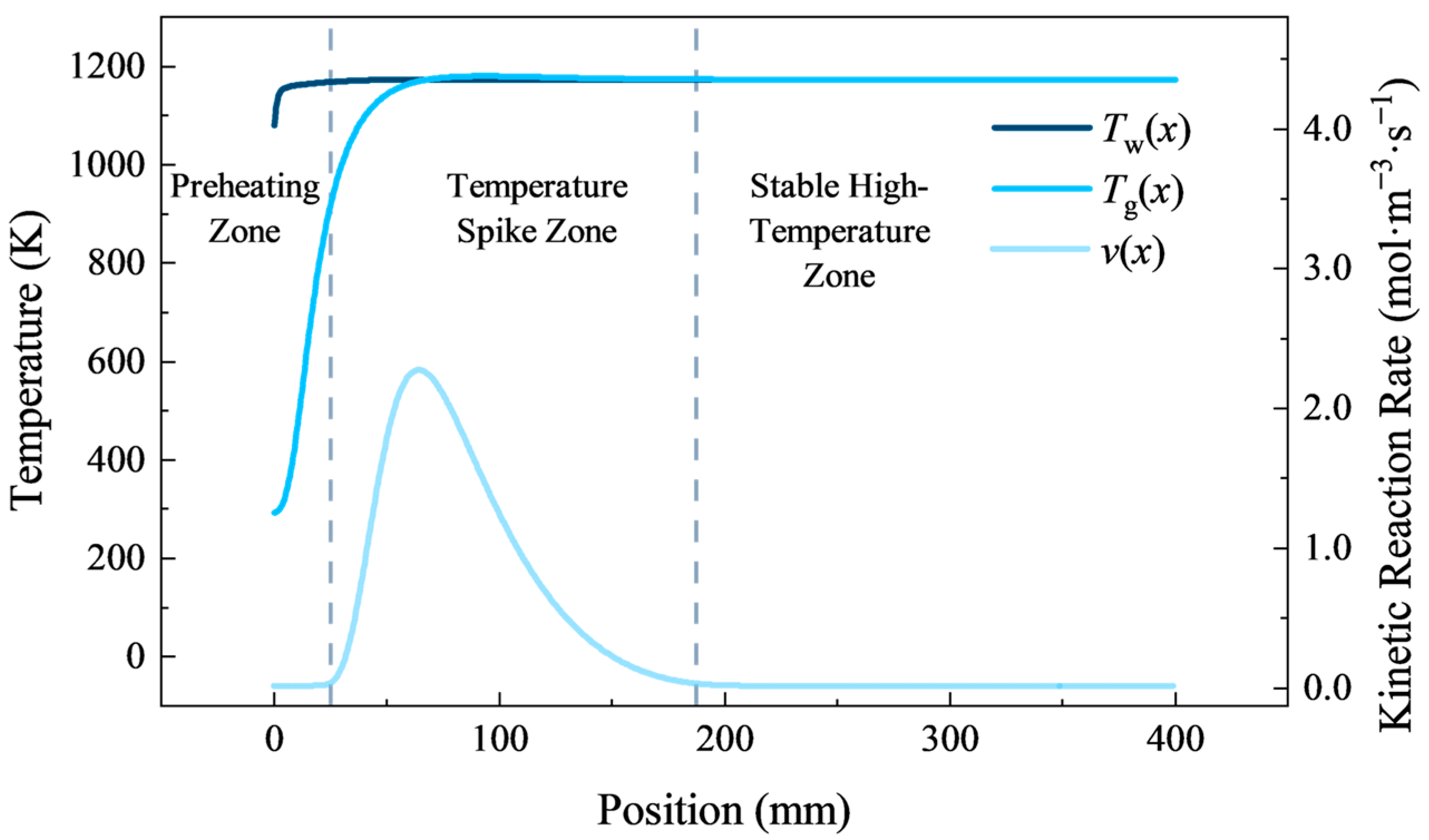
Low-concentration methane oxidation heat release in regenerator channels exhibits distinct stages, divided into preheating, temperature spike, and stable high-temperature zones based on dynamic heat transfer and reaction changes, as shown in Figure 2.
In the preheating zone, methane gas absorbs heat from the regenerator via convection after entry, with the temperature rising to ~1000 K (ignition temperature). The reaction is uninitiated, and heat transfer is the core process.
In the temperature spike zone, methane initiates oxidation. Initially, the gas temperature is lower than the wall; so, it continues absorbing heat. As the reaction intensifies, the heat release exceeds absorption, pushing the gas temperature ~20 K above the wall to form a local peak. After methane depletion, the gas releases heat to the regenerator, and the temperature drops back to the wall temperature, completing the spike.
In the stable high-temperature zone, the gas temperature matches the wall, forming the device’s core high-temperature area and laying the foundation for subsequent heat utilization.
This zoning stems from methane oxidation’s exothermic nature and gas–solid heat transfer balance, with dynamic changes in reaction intensity and heat transfer efficiency governing boundary shifts.

3.1.2. Effect of Operating Parameters on Heat Release During Low-Concentration Methane Oxidation

A series of numerical simulations were conducted to examine the effects of the inlet velocity, channel wall temperature, and concentration on the heat release during low-concentration methane oxidation.
(1)
Effect of inlet velocity
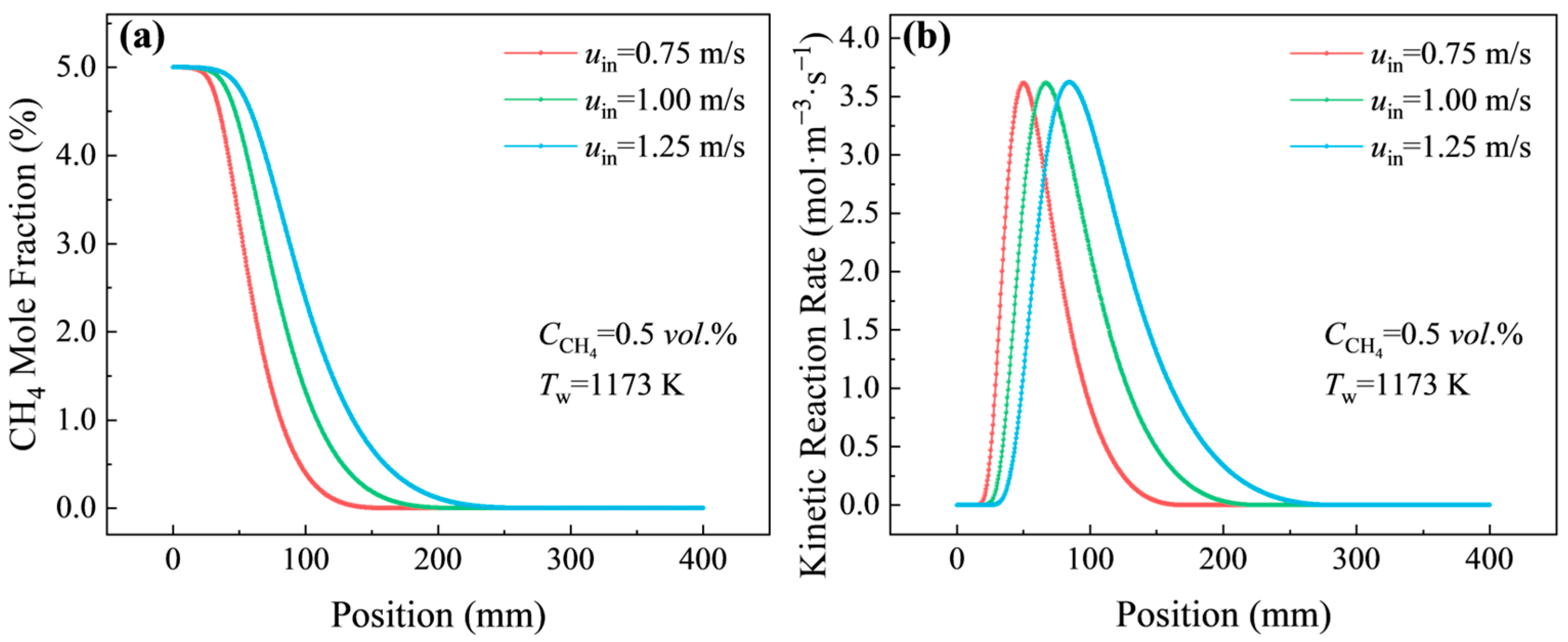
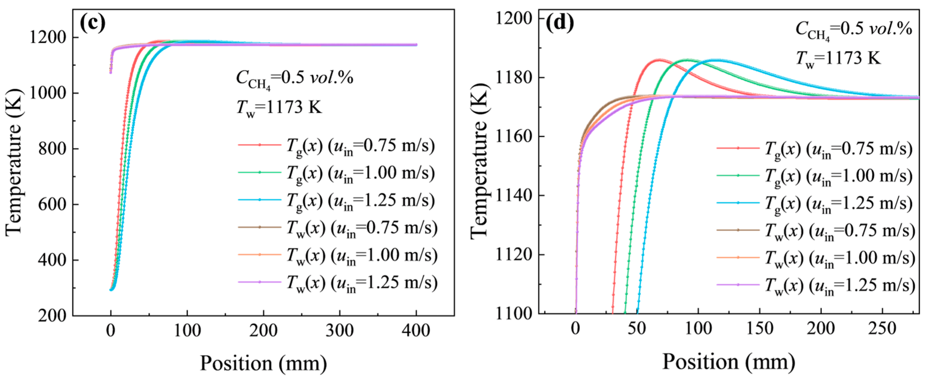
At a fixed methane concentration of 0.5 vol.% and wall temperature of 1173 K, variations in the inlet velocity (from 0.75 to 1.25 m/s) exert a notable impact on the spatiotemporal behavior of methane oxidation. As shown in Figure 3a–d, the onset of the reaction is visibly delayed, and the oxidation distance along the channel axial direction extends from 100 mm to 200 mm, while the peak reaction rate remains nearly unchanged. This phenomenon is rooted in two key factors: higher velocities significantly shorten methane’s residence time in the narrow channel, reducing the duration of effective heat exchange between the gas and the wall, which slows the mixture’s rise to the 1000 K ignition temperature. Additionally, the peak reaction rate is determined by intrinsic oxidation kinetics—dependent on temperature and reactant concentration rather than flow velocity—so only the spatial spread and timing of the reaction are altered and not its maximum intensity.
(2)
Effect of channel wall temperature
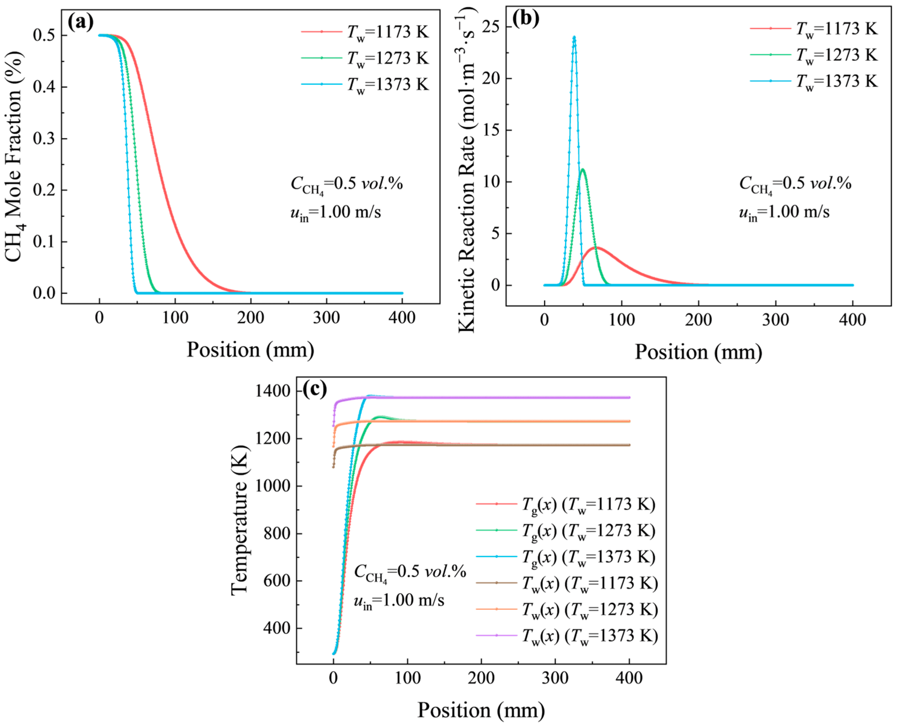
With the methane concentration fixed at 0.5 vol.% and the inlet velocity at 1.0 m/s, raising the channel wall temperature from 1173 K to 1373 K triggers dramatic changes in oxidation performance. Figure 4a,b illustrate that the peak reaction rate surges 5.3-fold (from 3.72 to 23.87 mol·m−3·s−1), and the oxidation distance shrinks sharply to approximately 30 mm. Temperature acts as the primary driver of methane activation. Higher temperatures enable more reactant molecules to overcome the activation barrier, thereby promoting C-H bond activation in methane and increasing the probability of effective collisions between methane and oxygen molecules, which in turn accelerates the reaction. In Figure 4c, when the wall temperature exceeds 1273 K, local temperature spikes of up to 30 K are observed in the channel. The reason is that, beyond 1273 K, the heat released by oxidation outpaces the regenerator’s heat storage capacity, leading to localized overheating, which may increase the risk of thermal damage or hot-spot formation on the channel wall.
(3)
Effect of methane concentration
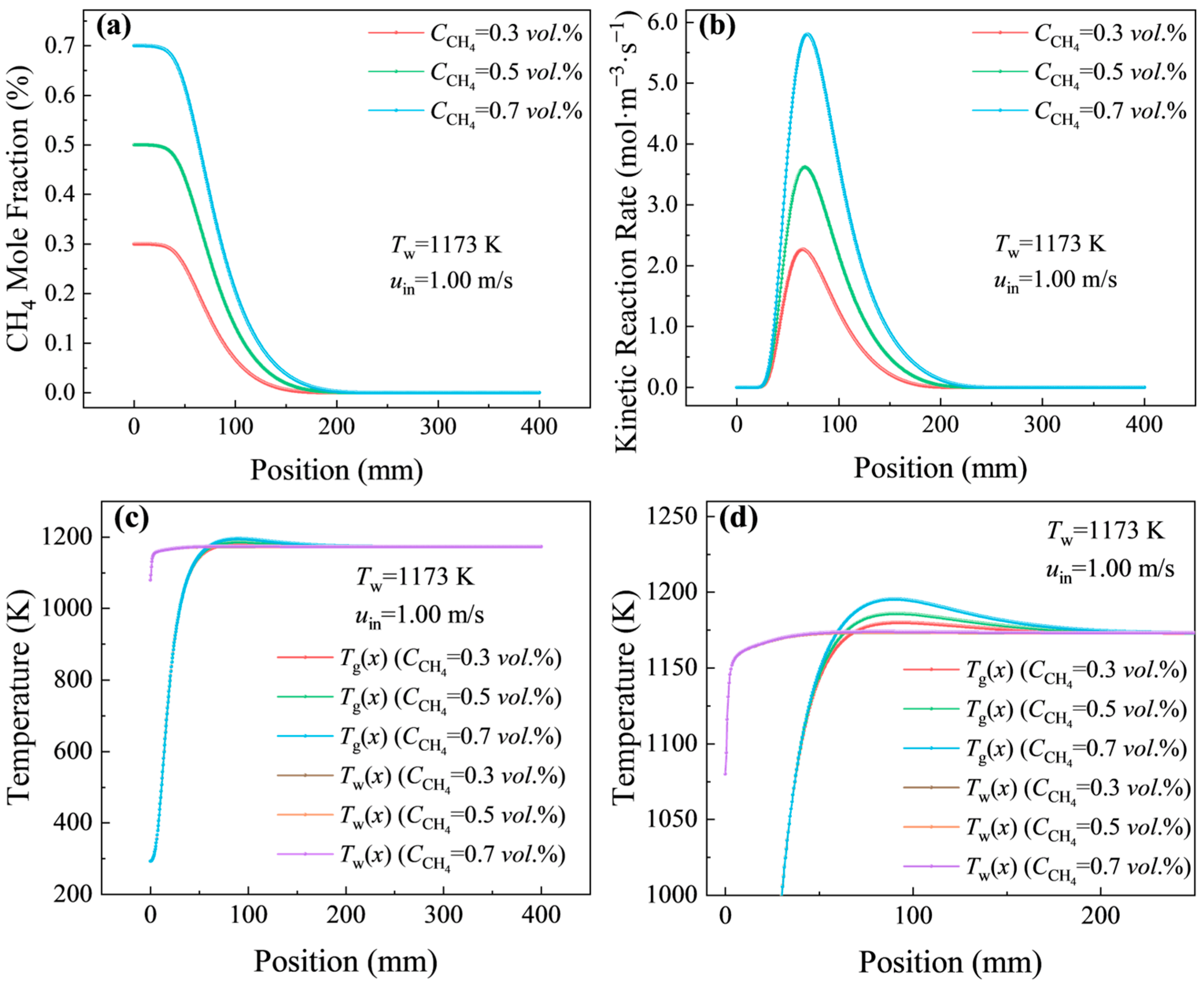
Fixing the inlet velocity at 1.0 m/s and the wall temperature at 1173 K, methane concentrations ranging from 0.3 to 0.7 vol.% all initiate a reaction at approximately 50 mm from the channel inlet, but their subsequent reaction behaviors differ significantly (Figure 5a–d). Lower concentrations (0.3 vol.%) shorten the oxidation distance by about 50 mm compared to higher concentrations, while higher concentrations (0.7 vol.%) push the peak reaction rate to 4.2 mol·m−3·s−1 and drive the gas temperature close to 1200 K. The reaction initiation is strictly dependent on the wall-driven heating process to reach the 1000 K ignition temperature; so, the onset position shows little sensitivity to the methane concentration under the present operating conditions. Lower concentrations deplete the limited combustible material more quickly, trimming the overall reaction distance, while higher concentrations increase the density of reactant molecules, enhancing the reaction intensity. Excessively high concentrations, however, lead to accumulated heat release that cannot be promptly dissipated, pushing the system temperature upward and leading to a higher local temperature rise and a higher risk of thermal non-uniformity.

3.2. Heat Release Behaviors During Pulverized Coal Oxidation in Regenerator Channels

3.2.1. Patterns of Heat Release During Pulverized Coal Oxidation

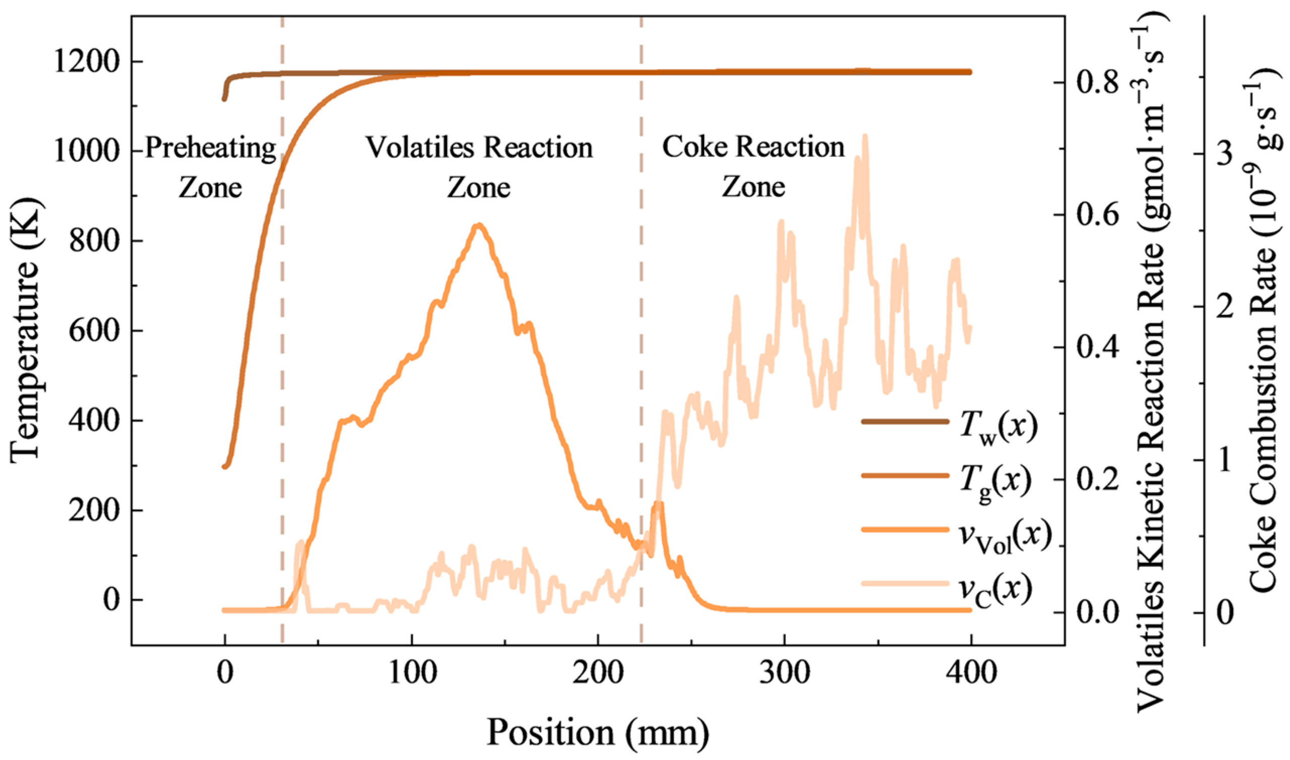
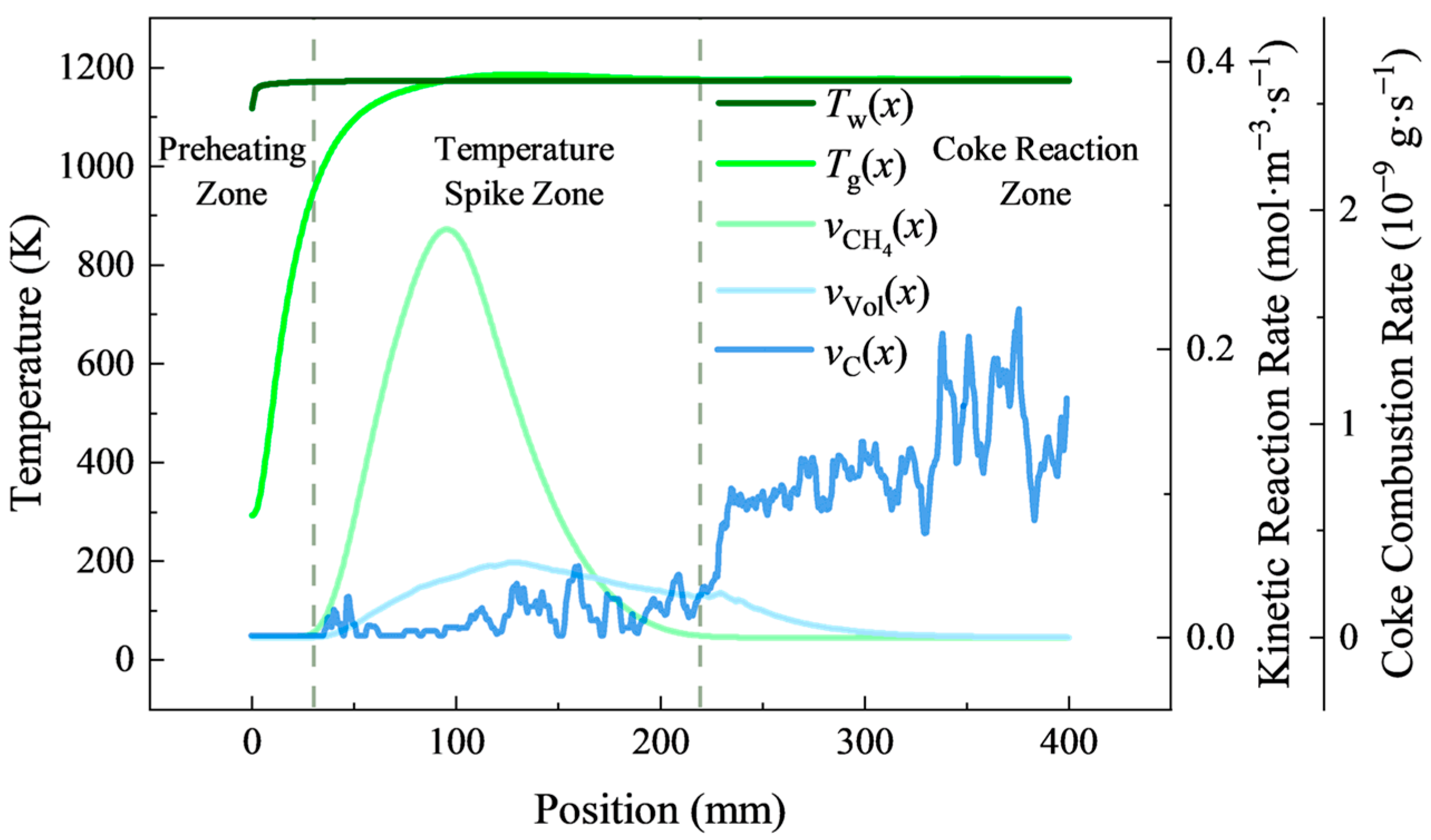
As shown in Figure 6, pulverized coal oxidation and heat release in the channel proceed in three successive stages: preheating, volatile reaction and coke reaction, which correspond to three distinct reaction zones respectively.
In the preheating zone, coal particles heat up via radiation and convection: moisture evaporates first, followed by volatile release. The particle temperature stays below the ignition point with no significant heat release.
In the volatile reaction zone, volatiles react with oxygen, peaking in rate at 140 mm and nearly depleting by 230 mm. The heat release is weak, with no gas temperature spike above the wall, as volatiles contribute less to coal’s energy than coke.
In the coke reaction zone, coke oxidizes as the primary heat source after volatile depletion, causing a slight gas temperature rise slightly above the wall (with limited overheating) until particles exit the channel.
The overall reaction cycle is longer than methane’s, with milder heat release—dictated by coal’s multi-component stepwise reaction nature.

3.2.2. Effect of Operating Parameters on Heat Release During Pulverized Coal Oxidation

This subsection investigates the effects of the inlet velocity, channel wall temperature, and pulverized coal feed rate on the heat release during pulverized coal oxidation.
(1)
Effect of inlet velocity
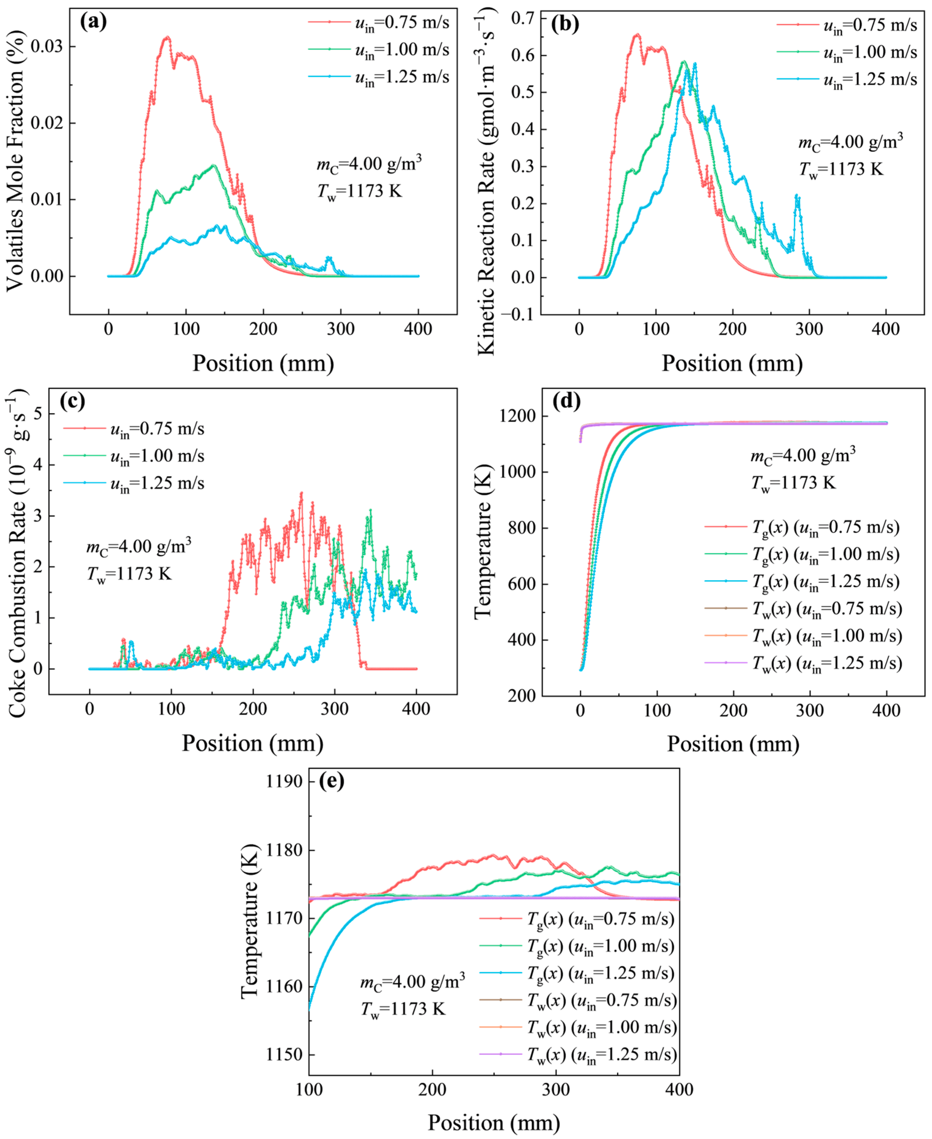
At a wall temperature of 1173 K and a coal feed rate of 4.00 g/m3, the inlet velocity has a decisive impact on the completeness of pulverized coal oxidation in the 3 mm-diameter channel. The results are presented in Figure 7a–e. At 0.75 m/s, coke achieves full burnout within 350 mm of the inlet, while at 1.25 m/s, unreacted coke exits the channel, and the volatile reaction rate is noticeably reduced. Low velocities extend the residence time of coal particles in the channel and promote particle convergence near the wall (driven by the Saffman force), which enhances the gas–solid contact area and heat transfer efficiency—both critical for coke oxidation, a slow heterogeneous reaction that requires sustained interaction with oxygen. High velocities, by contrast, accelerate particle transport through the channel, truncating the time available for volatile release and coke combustion, and weakening the necessary gas–particle interaction, ultimately lowering the overall reaction efficiency.
(2)
Effect of channel wall temperature
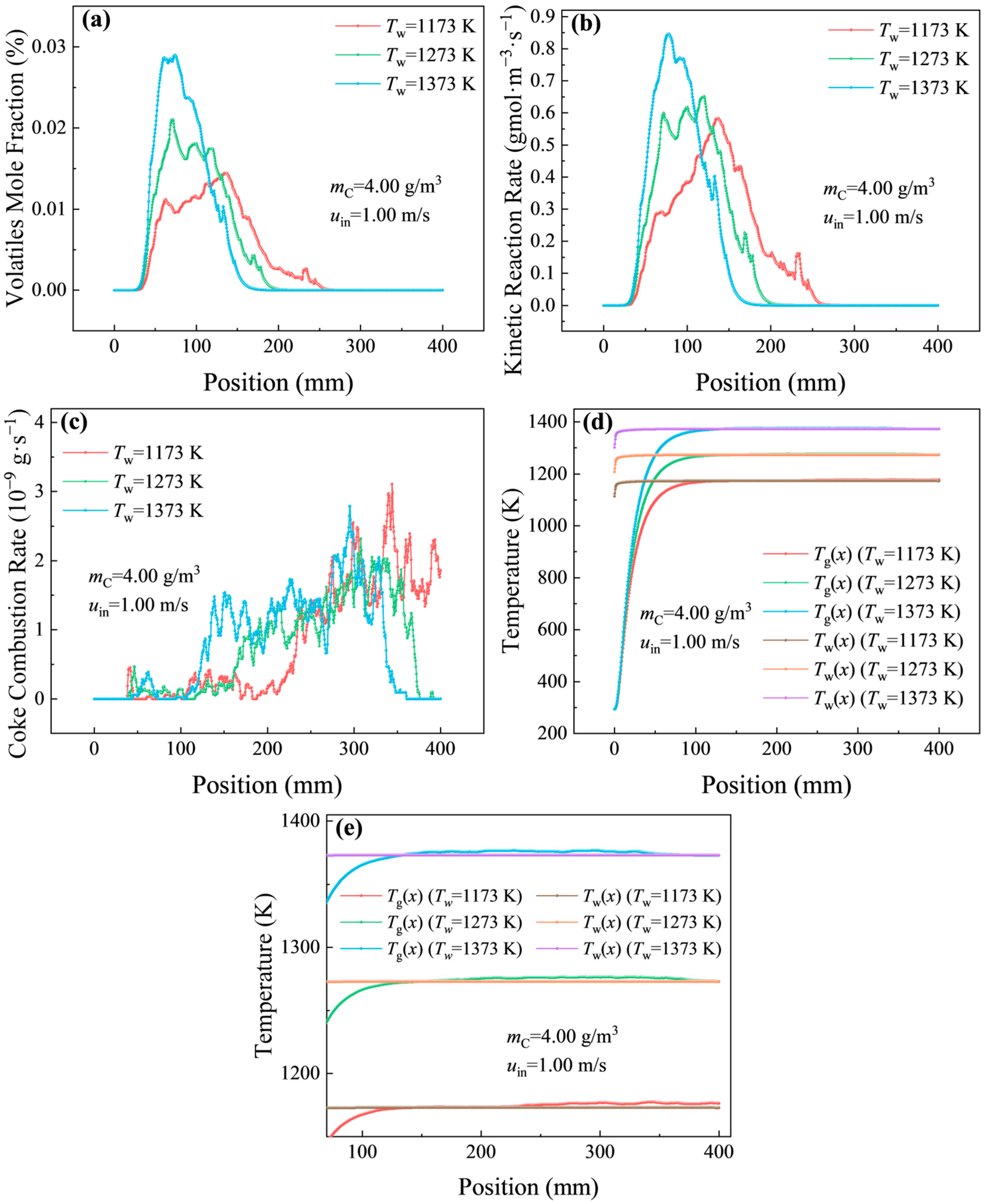
With the inlet velocity fixed at 1.0 m/s and the coal feed rate fixed at 4.00 g/m3, changing the wall temperature from 1173 K to 1373 K reshapes the entire pulverized coal reaction profile (Figure 8a–e): the volatile oxidation distance decreases from 220 mm to 100 mm, and at 1273 K, coke achieves complete oxidation within the full 400 mm length of the channel. Temperature accelerates both coal pyrolysis and oxidation processes: higher temperatures speed up the thermal cracking of coal macromolecules, releasing volatiles more rapidly, and boost coke oxidation kinetics. 1273 K emerges as a critical threshold—above this temperature, the kinetic conditions are sufficient to drive full coke combustion, but excessively high temperatures pose risks, including NOx formation from the oxidation of coal-bound nitrogen and thermal stress on the channel’s ceramic material.
(3)
Effect of pulverized coal feed rate
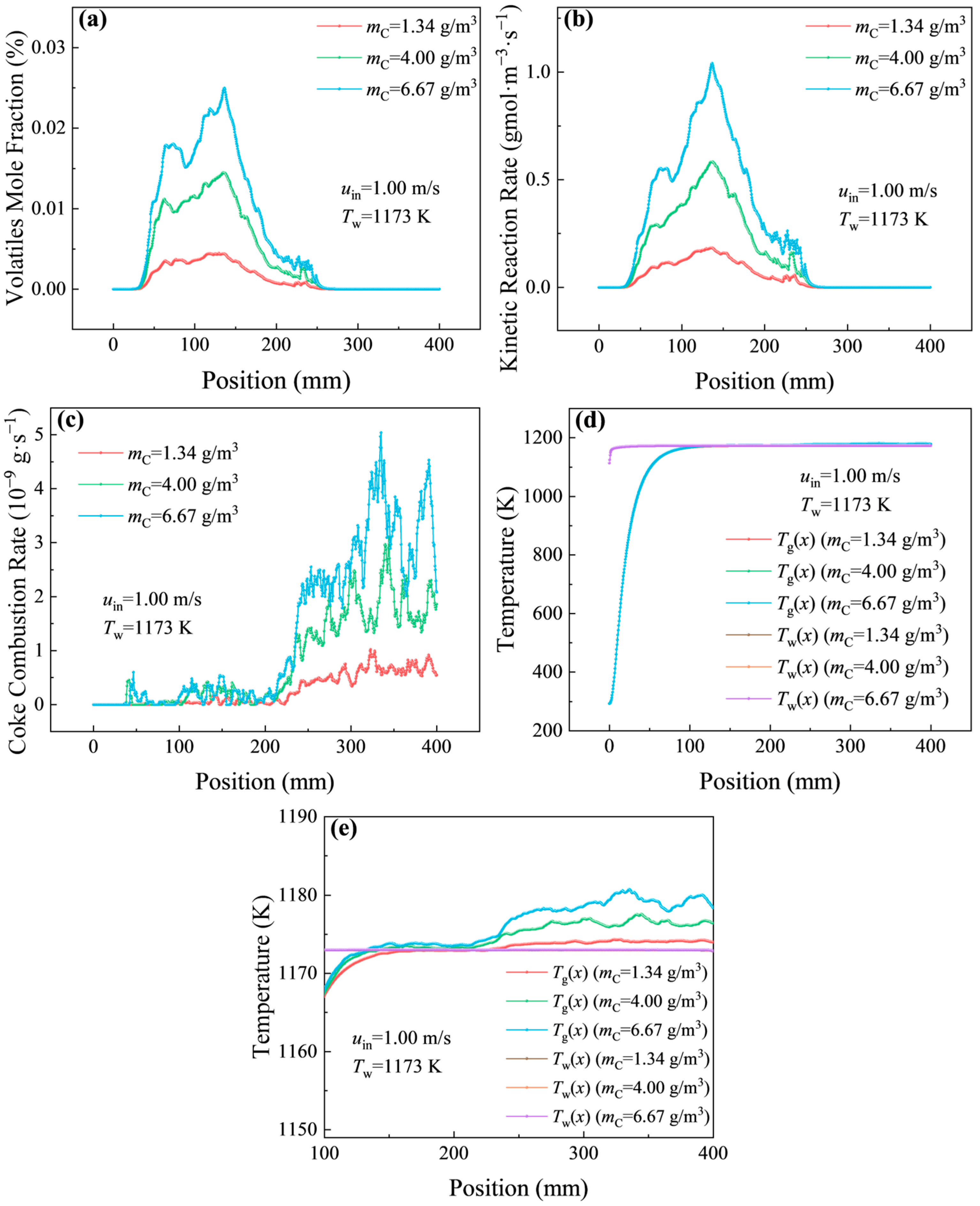
Figure 9a,b show that, at a constant wall temperature of 1173 K and an inlet velocity of 1.0 m/s, coal feed rates of 1.34, 4.00, and 6.67 g/m3 (whose heat release equivalents match 0.1, 0.3, and 0.5 vol.% methane, respectively) have no effect on the onset position of volatile reactions (consistently ~80 mm from the inlet) but increase the volatile reaction rate in direct proportion to the feed rate. The onset of volatile reactions is tied to coal’s fixed thermal decomposition temperature, a material property that is unaffected by feed rate, so the initiation position remains stable. Higher feed rates increase the total mass of coal particles entering the channel, leading to linear growth in volatile content and thus a proportional increase in reaction rate. As illustrated in Figure 9c–e, at the highest feed rate of 6.67 g/m3, the gas temperature rises to 1180 K, and the coke combustion rate increases with the feed rate but exhibits noticeable fluctuations. These fluctuations stem from uneven particle distribution in the channel—local overcrowding reduces oxygen availability to individual particles—while the elevated gas temperature arises from the total heat release exceeding the system’s dissipation capacity.

3.3. Heat Release Behaviors During Oxidation of Pulverized Coal-Dispersed Ventilation Air Methane in Regenerator Channels

3.3.1. Effect of Coal–Methane Heat Input Ratios on Heat Release During Oxidation of Pulverized Coal-Dispersed Ventilation Air Methane

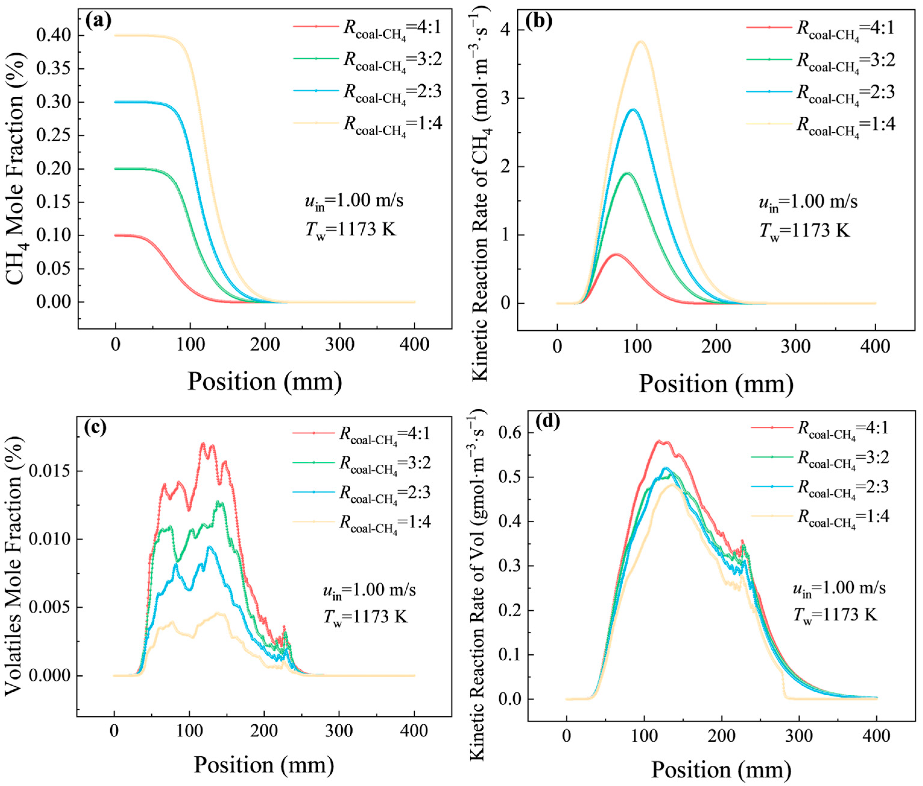
Based on the results in Section 3.1 and Section 3.2, an inlet velocity of 1.0 m/s and a wall temperature of 1173 K were determined. To investigate the effects of different coal–methane heat input ratios on oxidation and heat release, four ratios with 4:1, 3:2, 2:3 and 1:4 were adopted, corresponding to methane concentrations of 0.1–0.4 vol.% and coal feed rates of 5.34–1.34 g/m3, as presented in Figure 10. In this study, the evaluation of combustion performance is mainly based on the methane oxidation behavior, coke burnout characteristics, and the ability to maintain a sustained high-temperature region along the channel.
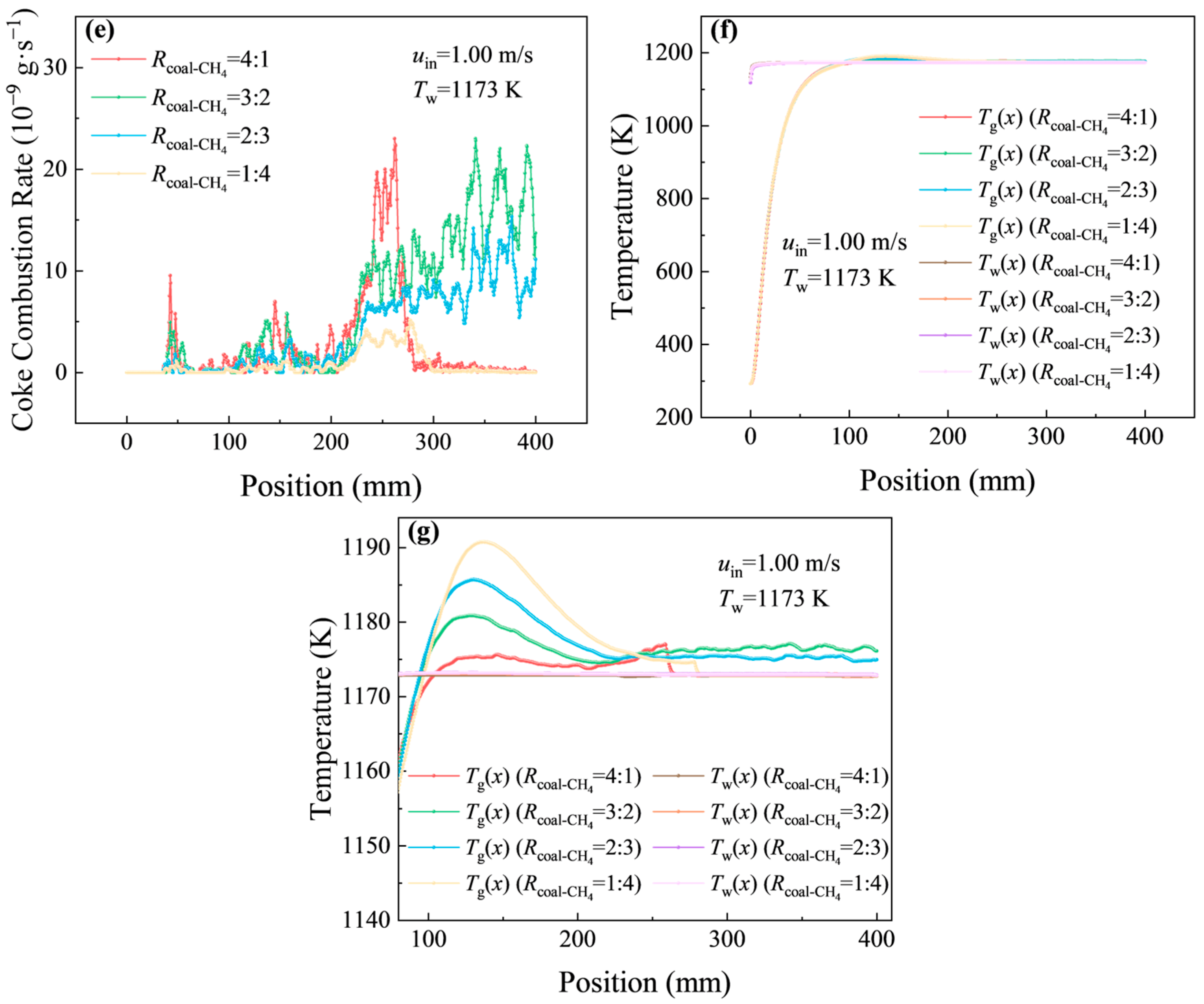
From Figure 10a,b, as the methane ratio increases, the onset of methane concentration decay delays from 50 mm (4:1) to over 100 mm (1:4), with a maximum shift exceeding 50 mm relative to pure methane combustion. The methane reaction starts within 50 mm in all cases, and its peak moves downstream slightly with rising methane concentration, extending the oxidation zone. The 4:1 case shows a smaller shift, indicating that a higher coal–methane ratio can weaken the reaction delay to some extent. Figure 10c,d illustrates that the volatile release and reaction intervals are similar among all ratios, and the peak values are nearly identical for 2:3 and 3:2, suggesting that the methane concentration has little influence on the volatile reaction behavior. As shown in Figure 10e, coke combustion rate increases with the coal input, reaching the highest in 4:1 and the lowest in 1:4. Coke is not fully consumed in 2:3 and 3:2, while major coke oxidation is completed within a 100 mm interval in 4:1 and 1:4. The 4:1 case shows slight tail combustion due to high particle concentration, and 1:4 achieves rapid burnout owing to insufficient coal loading, both presenting unbalanced single-fuel-dominated combustion. According to Figure 10f,g, the temperature rise in the upstream channel is dominated by methane and volatile oxidation, with a peak over-temperature of 20 K in 1:4, while the downstream heat release is mainly supplied by coke oxidation.
Overall, from an engineering perspective, the 4:1 ratio was considered more suitable because it maintained stronger coke oxidation under a relatively high coal loading while still achieving major burnout within the channel. However, the 4:1 and 1:4 cases were both characterized by pronounced single-fuel dominance and were therefore less suitable for elucidating the interaction mechanism between pulverized coal and methane. By contrast, the 3:2 and 2:3 cases both preserved appreciable contributions from the two fuels and were thus more representative of the co-combustion process. Considering that this study is centered on ultra-lean VAM oxidation, the 2:3 ratio was selected as the representative case for further analysis, because it retained clear dual-fuel interaction while still preserving methane as the principal gaseous heat-release component.

3.3.2. Patterns of Heat Release During Oxidation of Pulverized Coal-Dispersed Ventilation Air Methane in Regenerator Channels

This section examines the gas/wall temperature evolution and the reaction kinetics of methane, volatiles, and coke for the representative 2:3 coal–methane equivalent input ratio at an inlet velocity of 1.0 m/s and a wall temperature of 1173 K. The results are shown in Figure 11.
The co-combustion system shows a distinct staged heat-release pattern along the channel, while still retaining the fundamental characteristics of the single-fuel cases. In the preheating zone, the temperature rise is still mainly governed by heat transfer from the regenerative channel wall, which is consistent with the single-component combustion cases. However, compared with standalone methane oxidation, the onset of methane reaction shifts downstream after coal addition. This indicates that the presence of pulverized coal modifies the upstream thermal/species field before methane oxidation becomes dominant. Meanwhile, the heat released by volatile oxidation provides additional thermal support for the subsequent methane reaction.
In the temperature-spike zone, methane still exhibits higher reactivity than volatiles and remains the major contributor to rapid front-channel heat release. However, compared with pure methane combustion, its peak reaction rate is reduced, and its complete reaction distance is extended from about 150 mm to about 220 mm, indicating that the methane heat release is redistributed over a wider axial range in the blended system. By contrast, the volatile sub-process changes only slightly, which is consistent with the observation in Figure 10 that the volatile release and reaction intervals remain similar for the intermediate coal–methane ratios. In addition, the local over-temperature is limited to about 20 K, suggesting that coal addition does not sharpen the front-channel thermal spike, but instead, it broadens the effective heat-release region.
The coke-reaction zone is the most distinctive feature of co-combustion. After the rapid methane oxidation in the front channel weakens, coke oxidation gradually becomes the dominant downstream heat source. Unlike the pure methane case, where the gas temperature tends to decrease once methane is consumed, the delayed heat release from coke oxidation compensates for the post-methane temperature drop and helps maintain a longer high-temperature interval in the channel. This downstream thermal compensation also distinguishes the blended system from standalone pulverized-coal combustion, in which the early high-temperature support is comparatively insufficient.
Overall, the coupled characteristic of the present system lies in the complementary axial distribution of heat release between methane and pulverized coal. Methane is mainly responsible for rapid upstream heating, whereas pulverized coal, especially through subsequent coke oxidation, sustains downstream heat release and prolongs the high-temperature region. Therefore, the co-combustion process does not simply increase the instantaneous heat-release intensity of a single component but rather redistributes the heat-release process along the channel to achieve a more stable thermal field.

4. Conclusions

This numerical study explores the heat release behaviors of methane, pulverized coal, and their mixtures in regenerator channels, focusing on operational parameter effects and coal–methane heat input ratios. The key findings are as follows:
(1)
Low-concentration methane oxidation involves preheating, temperature spike and stable high-temperature stages. The inlet velocity alters the reaction’s spatial onset and axial distance without changing the peak rate. The wall temperature dominantly controls the oxidation intensity, with the rate increasing 5.3 times from 3.72 to 23.87 mol·m−3·s−1, as the temperature rises from 1173 K to 1373 K. The methane concentration has little effect on ignition onset, but higher concentrations increase the peak reaction rate, temperature rise, and oxidation-zone length.
(2)
Pulverized coal oxidation proceeds stepwise through preheating, volatile and coke combustion. The inlet velocity determines the combustion completeness. Here, 0.75 m/s enables full coke burnout within 350 mm, and higher velocities lead to unreacted coke discharge. A wall temperature above 1273 K ensures full combustion in the channel. The volatile reaction rate increases linearly with the coal feed rate.
(3)
Among the four tested coal–methane heat input ratios, the 4:1 case shows the most favorable burnout behavior from an engineering perspective, whereas the 2:3 case is more suitable as a representative condition for mechanistic analysis because it preserves the dual-fuel interaction while maintaining methane as the dominant research object. Under this representative co-combustion condition, methane provides rapid upstream heat release, whereas pulverized coal, especially through subsequent coke oxidation, sustains downstream heat release. This complementary heat-release pattern delays the completion of methane oxidation from about 150 mm to about 220 mm, alleviates the temperature drop after methane consumption, and helps maintain the local temperature peak within about 20 K above the wall.

Supplementary Materials

The following supporting information can be downloaded at https://www.mdpi.com/article/10.3390/en19112600/s1, Figure S1. Mesh division of the circular cross-section channel and schematic diagram of the physical model; Figure S2. Verification of mesh-independence of the oxidation model; Table S1. Comparison of measured and numerically simulated regenerator channel temperatures; Table S2. Nomenclature for symbols in Equations (1)–(18).

Author Contributions

Conceptualization, T.Z. and Z.Y.; methodology, T.Z. and J.W.; validation, Z.Z. and Y.L.; formal analysis, J.W. and Z.J.; investigation, T.Z. and J.Z.; writing—original draft preparation, T.Z.; writing—review and editing, Z.Z., J.W., Y.L., J.Z., Z.J. and Z.Y.; supervision, Z.Z. and Z.Y.; project administration, Z.Z. and Z.Y.; funding acquisition, Z.Z. and Z.Y. All authors have read and agreed to the published version of the manuscript.

Funding

This research was funded by the National Science and Technology Major Project (No.2026ZD1701901), the National Natural Science Foundation of China (No.52276099, No.52174227), and the Special Project of Science and Technology Innovation and Entrepreneurship Fund of Tiandi Science & Technology Co., Ltd. (No.2023-2-TD-KJHZ003).

Data Availability Statement

The data presented in this study are available in the article and the Supporting Information. No additional data are available.

Conflicts of Interest

The authors declare no conflicts of interest. The funders had no role in the design of the study; in the collection, analyses, or interpretation of data; in the writing of the manuscript; or in the decision to publish the results.

Abbreviations

The following abbreviations are used in this manuscript:
VAMVentilation Air Methane
TFRRsThermal Flow Reversal Reactors
CFDComputational Fluid Dynamics
LHVLower Heating Value
DODiscrete Ordinates
DPMDiscrete Phase Model
NOxNitrogen Oxides

References

  1. Song, C.; Zhu, J.-J.; Willis, J.L.; Moore, D.P.; Zondlo, M.A.; Ren, Z.J. Methane emissions from municipal wastewater collection and treatment systems. Environ. Sci. Technol. 2023, 57, 2248–2261. [Google Scholar] [CrossRef]
  2. Song, S.; Lyu, Y.; Guo, B.; Liu, H.; Jin, Y.; Ran, J.; Niu, J. Photothermal synergistic empowerment of Ni/Ce1−xZrxO2 catalyst for DRM: Photothermal coupling regulation and product generation mechanism. DeCarbon 2025, 10, 100131. [Google Scholar] [CrossRef]
  3. Wang, X.; Zhou, F.; Ling, Y.; Xiao, Y.; Ma, B.; Ma, X.; Yu, S.; Liu, H.; Wei, K.; Kang, J. Overview and outlook on utilization technologies of low-concentration coal mine methane. Energy Fuels 2021, 35, 15398–15423. [Google Scholar] [CrossRef]
  4. Yin, F.; Nie, B.; Wu, J.; Yang, Y.; Wei, Y.; Zhu, T. Combustion characteristics of ventilation air methane blending with dimethyl ether in a thermal reverse flow reactor. Energy Fuels 2022, 37, 547–559. [Google Scholar] [CrossRef]
  5. Iwaniszyn, M.; Pawlaczyk-Kurek, A.; Kołodziej, A.; Rotkegel, A.; Tańczyk, M.; Skiba, J.; Hildebrandt, R.; Bałaga, D.; Siegmund, M.; Gancarczyk, A. Ventilation Air Methane (VAM) utilisation: Comparison of the thermal and catalytic oxidation processes. Energies 2025, 18, 1428. [Google Scholar] [CrossRef]
  6. Shi, Y.; Liu, Y.; Zhou, Y.; Sun, P.; Mao, M.; Zhang, Y. Study on dynamic heat extraction characteristics of heat exchanger tube embedded in thermal flow reverse reactor for heat recovery. Process Saf. Environ. Prot. 2022, 162, 846–858. [Google Scholar] [CrossRef]
  7. Tang, A.; Yang, J.; Shao, S.; Cai, T.; Zhang, Z.; Xiao, L. Experimental investigations on the thermal destabilization and performance enhancement of ventilation air methane in a reversed flow oxidation reactor. Chem. Eng. Process. Process Intensif. 2024, 204, 109958. [Google Scholar] [CrossRef]
  8. Yang, Z.; Hussain, M.Z.; Marín, P.; Jia, Q.; Wang, N.; Ordóñez, S.; Zhu, Y.; Xia, Y. Enrichment of low concentration methane: An overview of ventilation air methane. J. Mater. Chem. A 2022, 10, 6397–6413. [Google Scholar] [CrossRef]
  9. Zhang, G.; Li, Q.; Liu, X.; Lin, B.; Li, D. Investigations on the mitigation of ventilation air methane and energy recovery in site trial thermal flow-reversal reactor. Chem. Eng. Process. Process Intensif. 2022, 170, 108703. [Google Scholar] [CrossRef]
  10. Li, S.; Zhang, J.; Xie, S.; Gao, K.; Zhang, H. Autoignition of methane/coal particle/air mixture under constant-volume conditions. Combust. Flame 2023, 258, 113111. [Google Scholar] [CrossRef]
  11. Rahman, M.; Andersson, H.I. Heat and fluid flow in revolving fluid-particle suspensions with suction. Comput. Therm. Sci. 2020, 12, 417–428. [Google Scholar] [CrossRef]
  12. Wang, S.; Luo, K.; Hu, C.; Lin, J.; Fan, J. CFD-DEM simulation of heat transfer in fluidized beds: Model verification, validation, and application. Chem. Eng. Sci. 2019, 197, 280–295. [Google Scholar] [CrossRef]
  13. Patro, B.; Kiran Kumar, K.; Jaya Krishna, D. Prediction of local heat transfer characteristics of dilute gas-solid flows through an adiabatic, horizontal pipe. Heat Transf. Asian Res. 2019, 48, 1987–2006. [Google Scholar] [CrossRef]
  14. Taofeeq, H.; Al-Dahhan, M. Heat transfer and hydrodynamics in a gas-solid fluidized bed with vertical immersed internals. Int. J. Heat Mass Transf. 2018, 122, 229–251. [Google Scholar] [CrossRef]
  15. Li, B.; Ma, M.; Yu, Y.; Chen, C.; Zhou, Z. Particle scale study on heat transfer of gas-solid spout fluidized bed with hot gas injection. Part. Sci. Technol. 2019, 37, 781–790. [Google Scholar] [CrossRef]
  16. Bisognin, P.C.; Bastos, J.C.S.C.; Meier, H.F.; Padoin, N.; Soares, C. Influence of different parameters on the tube-to-bed heat transfer coefficient in a gas-solid fluidized bed heat exchanger. Chem. Eng. Process. Process Intensif. 2020, 147, 107693. [Google Scholar] [CrossRef]
  17. Uwitonze, H.; Kim, A.; Kim, H.; Brigljević, B.; Ly, H.V.; Kim, S.-S.; Upadhyay, M.; Lim, H. CFD simulation of hydrodynamics and heat transfer characteristics in gas-solid circulating fluidized bed riser under fast pyrolysis flow condition. Appl. Therm. Eng. 2022, 212, 118555. [Google Scholar] [CrossRef]
  18. Kim, J.; Lee, S.; Tahmasebi, A.; Jeon, C.-H.; Yu, J. A review of the numerical modeling of pulverized coal combustion for high-efficiency, low-emissions (HELE) power generation. Energy Fuels 2021, 35, 7434–7466. [Google Scholar] [CrossRef]
  19. Zhu, S.; Zhu, J.; Lyu, Q. NOx emissions of pulverized coal combustion in high-temperature flue gas. Asia-Pac. J. Chem. Eng. 2020, 15, e2534. [Google Scholar] [CrossRef]
  20. Hashimoto, N.; Hayashi, J. Coal particle devolatilization and soot formation in pulverized coal combustion fields. KONA Powder Part. J. 2021, 38, 168–188. [Google Scholar] [CrossRef]
  21. Zhang, T.; Hu, Z.; Zhou, Y. The determination method of the ignition modes of single coal particle with a transient coal ignition and combustion model. Combust. Flame 2022, 241, 112092. [Google Scholar] [CrossRef]
  22. Yang, P.; Guo, W.; Yu, Z.; Gao, K.; Jing, W.; Jie, Z.; Shang, J.; Yang, B.; Wu, Z. Modified network kinetic model for coal pyrolysis with high-value products and low carbon emissions. Appl. Energy 2023, 351, 121763. [Google Scholar] [CrossRef]
  23. Launder, B.E.; Spalding, D.B. The numerical computation of turbulent flows. Comput. Methods Appl. Mech. Eng. 1974, 3, 269–289. [Google Scholar] [CrossRef]
  24. Benim, A.C.; Deniz Canal, C.; Boke, Y.E. A validation study for RANS-based modelling of swirling pulverized fuel flames. Energies 2021, 14, 7323. [Google Scholar] [CrossRef]
  25. Yang, X.; Xi, T.; Qin, Y.; Zhang, H.; Wang, Y. Computational fluid dynamics-discrete phase method simulations in process engineering: A review of recent progress. Appl. Sci. 2024, 14, 3856. [Google Scholar] [CrossRef]
  26. Varaksin, A.Y.; Ryzhkov, S.V. Mathematical modeling of gas-solid two-phase flows: Problems, achievements and perspectives (a review). Mathematics 2023, 11, 3290. [Google Scholar] [CrossRef]
  27. Du, F.; Guo, Y.; Wang, L.; Xu, C.; Zhou, A.; Wang, G. EDEM-FLUENT coupled simulation of coal-gas outburst two-phase flow. Energy Explor. Exploit. 2021, 39, 1786–1802. [Google Scholar] [CrossRef]
  28. Sommerfeld, M.; Taborda, M.A. Understanding solid particle transport in a gas cyclone separator. Int. J. Multiph. Flow 2024, 181, 104992. [Google Scholar] [CrossRef]
  29. Nguyen, P.D.; Nguyen, H.T.; Domingo, P.; Vervisch, L.; Mosca, G.; Gazdallah, M.; Lybaert, P.; Feldheim, V. Flameless combustion of low calorific value gases, experiments, and simulations with advanced radiative heat transfer modeling. Phys. Fluids 2022, 34, 045123. [Google Scholar] [CrossRef]
  30. Mazumder, S.; Roy, S.P. Modeling thermal radiation in combustion environments: Progress and challenges. Energies 2023, 16, 4250. [Google Scholar] [CrossRef]
  31. Ge, W.; David, C.; Modest, M.F.; Sankaran, R.; Roy, S.P. Comparison of spherical harmonics method and discrete ordinates method for radiative transfer in a turbulent jet flame. J. Quant. Spectrosc. Radiat. Transf. 2023, 296, 108459. [Google Scholar] [CrossRef]
Figure 1. Schematic illustration of the oxidation process of pulverized coal-dispersed VAM in a regenerative oxidizer.
Energies 19 02600 g001
Figure 2. Temperature and reaction rate distribution in the channel for methane oxidation.
Energies 19 02600 g002
Figure 3. Effect of inlet velocity on key parameter distributions along the channel. (a) Methane concentration, (b) reaction rate, (c) temperature, (d) temperature (partial enlarged detail).
Energies 19 02600 g003aEnergies 19 02600 g003b
Figure 4. Effect of channel wall temperature on key parameter distributions along the channel. (a) Methane concentration, (b) reaction rate, (c) temperature.
Energies 19 02600 g004
Figure 5. Effect of methane concentration on key parameter distributions along the channel. (a) Methane concentration, (b) reaction rate, (c) temperature, (d) temperature (partial enlarged detail).
Energies 19 02600 g005
Figure 6. Temperature distribution and reaction rate distribution in the channel for pulverized coal oxidation reaction.
Energies 19 02600 g006
Figure 7. Effect of inlet velocity on key parameter distributions along the channel. (a) Volatile concentration, (b) volatile reaction rate, (c) coke combustion rate, (d) temperature, (e) temperature (partial enlarged detail).
Energies 19 02600 g007
Figure 8. Effect of channel wall temperature on key parameter distributions along the channel. (a) Volatile concentration, (b) volatile reaction rate, (c) coke combustion rate, (d) temperature, (e) temperature (partial enlarged detail).
Energies 19 02600 g008
Figure 9. Effect of pulverized coal feed rate on key parameter distributions along the channel. (a) Volatile concentration, (b) volatile reaction rate, (c) coke combustion rate, (d) temperature, (e) temperature (partial enlarged detail).
Energies 19 02600 g009
Figure 10. Effect of coal–methane heat input ratios on key parameter distributions along the channel. (a) Methane concentration, (b) methane reaction rate, (c) volatile concentration, (d) volatile reaction rate, (e) coke combustion rate, (f) temperature, (g) temperature (partial enlarged detail).
Energies 19 02600 g010aEnergies 19 02600 g010b
Figure 11. Temperature distribution and reaction rate distribution in the channel for pulverized coal/methane oxidation reaction.
Energies 19 02600 g011
Table 1. Simulation boundary conditions and initial conditions.
No.ParameterCondition
1Solver type3ddp
2Turbulence modelRealizable k-ε
3Radiation modelDO
4Species transport modelFinite-rate/eddy dissipation
5Inlet boundary conditionVelocity inlet
6Outlet boundary conditionPressure outlet
7Pressure–velocity couplingSimple
Table 2. Parameters for proximate analysis and ultimate analysis of coal samples.
ItemSymbolUnitValue
Proximate AnalysisMoisture (air-dried basis)Mad%2.16
Ash (as-received basis)Aar%3.41
Volatile matter (dry ash-free basis)Vdaf%36.74
Fixed carbon (as-received basis)FC,ar%61.82
Ultimate AnalysisCarbon (as-received basis)wC,ar%73.6
Hydrogen (as-received basis)wH,ar%4.71
Oxygen (as-received basis)wO,ar%14.82
Nitrogen (as-received basis)wN,ar%6.32
Sulfur (as-received basis)wS,ar%0.55
Disclaimer/Publisher’s Note: The statements, opinions and data contained in all publications are solely those of the individual author(s) and contributor(s) and not of MDPI and/or the editor(s). MDPI and/or the editor(s) disclaim responsibility for any injury to people or property resulting from any ideas, methods, instructions or products referred to in the content.