Article

The Environmental Profile of a Building-Integrated Concentrating Photovoltaic System with Hexagonal Concentrators and Micro-Tracking: Embodied Energy and Other Indicators

by
Chrysovalantou Lamnatou
,
Santiago Maestro
and
Daniel Chemisana
*
Polytechnic School, University of Lleida, Jaume II 69, 25001 Lleida, Spain
*
Author to whom correspondence should be addressed.
Energies 2026, 19(11), 2578; https://doi.org/10.3390/en19112578
Submission received: 27 April 2026 / Revised: 16 May 2026 / Accepted: 18 May 2026 / Published: 27 May 2026
(This article belongs to the Section A2: Solar Energy and Photovoltaic Systems)

Abstract

This paper aims to evaluate the eco-profile of a building-integrated concentrating photovoltaic system (photovoltaic-cell electrical efficiency: 21.6%; geometrical concentration ratio: 12.5×), extending previous work on the design and energetic/optical performance of this system (University of Lleida, Spain). There is a lack of studies on the eco-profile of these technologies; for this reason, this study is based on environmental life cycle assessment (case study: a building in Barcelona; tools: SimaPro/ecoinvent, inventory-of-carbon-and-energy). Focusing on global warming potential and cumulative energy demand, the impacts range from 341 to 507 kg CO2.eq/m2 and from 5660 to 7505 MJprim/m2. Energy and greenhouse-gas payback times vary between 2.5 and 6.7 years and are shorter than the useful life of this energy-generating element (pessimistic scenario: 15 years). Avoided-impact calculations have also been performed, verifying the benefits of this system during the use phase. Overall, the results are comparable to those of traditional photovoltaic systems. The additional advantage of the proposed modules is that they serve as an atrium and offer illumination, successfully combining the benefits of concentrating photovoltaics (high efficiency; reduction in the amount of solar-cell material required), two optical media (achromatic doublets), hexagonal solar concentrators (high packing efficiency) and micro-tracking (overcoming limitations of bulky external trackers).

1. Introduction

The reliance on fossil fuels has led to serious environmental problems, undermining sustainable development. For this reason, new/eco-friendly technologies are necessary to reduce reliance on fossil fuels and enable efficient energy harvesting [1].
Considering the fact that energy demand is growing and buildings are one of the most polluting sectors [2], it is of the utmost importance to reduce the ecological impacts in the building sector. To this end, building-integrated concentrating photovoltaic (BICPV) technologies provide a way to achieve this goal by using small quantities of materials for photovoltaic (PV) cells (solar cells) [3].
As for concentrating photovoltaics (CPVs), in general, these systems can be classified into three categories, depending on a parameter known as the geometrical concentration ratio. This is one way to classify these technologies [4]. Examples of low-concentrating BICPV or BICPV/thermal modules include solar curtain walls [5], solar windows [6], and solar louvres [7]. Medium- and high-concentrating PV panels usually need big and complicated solar trackers, and for this reason, they are not commonly used as building-integrated components [4]. It is worth mentioning two examples. One example is of a façade-integrated high-concentrating PV installation with two-axis tracking [8], and another example is of a BIPV/thermal concentrator for façades [9]. The results showed that, for façade-integrated solar panels, it is better to use static solar concentrators with medium to low concentration ratios [9].
Although the above-mentioned systems are interesting, most of them can only be used in certain cases, and there are drawbacks and difficulties when it comes to building integration. In order to address these issues, alternative designs were proposed. The goal was to incorporate the solar tracking system into the CPV modules, i.e., to develop a kind of concentrator known as a tracking-integrated solar concentrator. This specific type of solar concentrator involves layers of optical elements (small components) and PV cells. The aim is to track the daily movement of the sun using small movements of the tracker (the term used is micro-tracking) [10] and develop compact CPV modules (in certain cases, the term used is micro-CPV) appropriate for applications involving building integration, as well as CPV panels that generate power and provide natural-light control [10]. It is worth mentioning the example of the Insolight solar system with micro-tracking technologies [10]. Other examples of solar systems with micro-tracking can be found in references [11,12].
Regarding BICPVs, there is an interest in CPVs with micro-tracking and in micro-CPV, but more research is needed, considering a parameter that influences the performance of these solar panels (particularly in the case of systems with refractive elements), namely chromatic aberration [13]. Given the aforementioned concerns, Maestro et al. [14] designed and investigated a novel CPV system with hexagonal lenses, micro-tracking and optical elements that minimise the problem of field curvature aberration. Additional advantages are that it also minimises chromatic aberration [14] thanks to the use of two refractive materials [15] and that it is appropriate for applications involving building integration [14].
Considering the importance of environmental life cycle assessment (LCA), this paragraph presents examples of BIPV and BIPV/thermal LCA studies. BICPV/thermal modules were studied with the aim of comparing these modules and traditional solar panels, verifying the comparative advantages of the proposed BICPV/thermal modules from an environmental standpoint [16]. A BIPV/thermal prototype for façades was evaluated, with the goal of identifying the main environmental challenges [17]. With respect to BICPV environmental payback times, one study revealed that Paris had long greenhouse-gas payback times (GHG PBTs) [18]. Luu et al. [19] investigated the ecodesign of emerging BIPV technologies based on environmental LCA and life cycle cost analysis. It was found that it is necessary to improve the efficiency and lifespan of perovskite materials and reduce the cost of PV-cell manufacturing so that these materials can compete with traditional silicon-based BIPVs.
The above-cited LCA publications [16,17,18,19], as well as the review articles [20,21,22], show that little research has been conducted on the LCA of BICPV and BICPV/thermal modules based on methods and indicators that provide information about various environmental issues. Additionally, there is a clear gap in the literature on LCA of BIPV systems with CPVs and micro-tracking technologies. The review papers [20,21,22] do not mention LCA studies on BICPV systems with micro-trackers.
Considering environmental issues and the significance of environmental LCA for different technologies (PV cells [22]; PV/thermal modules [23]; smart windows with electrochromic devices [24]), the goal of the present analysis is to provide a comprehensive picture of the eco-profile of an innovative CPV glazing element with micro-tracking, achromatic doublet and hexagonal concentrators, replying to unanswered questions (impacts of the materials and avoided impacts during the use phase) related to the proposed modules/technologies and extending the authors’ previous work [14] on the energetic/optical performance of this system. To this end, an LCA model based on different types of environmental indicators has been developed. One crucial question is whether these new PV modules are environmentally competitive with the traditional ones.
The proposed LCA model involves different materials, recycling, energy use (considering cumulative energy demand (CED) and primary energy input), global warming (considering global warming potential (GWP) and CO2.eq emissions), energy payback times (EPBTs), GHG PBTs, and other indicators. This follows from the fact that it is very useful to have information on the eco-profile of various PV modules/systems across their life cycles [16]. By using LCA tools, it is possible to pinpoint important features of these technologies and opportunities for improvements in their eco-profiles [16].
The innovation of this study stems from:
(a) The system itself [14]. The proposed modules are innovative because they combine CPVs, static optical elements, two optical media, hexagonal solar concentrators and micro-tracking technologies, offering an avant-garde semitransparent glazing element [14]. In other words, the proposed solar modules integrate avant-garde technologies to achieve effective daylighting control and offer valuable services towards zero-energy buildings. The review papers [20,21,22] show gaps in the literature on BICPV LCA and do not mention publications on the LCA of BICPVs with micro-trackers and other specific characteristics that the proposed system has. Therefore, more research is needed in this field in order to explore how different types of building-integrated modules influence the environmental profile of the whole system. For instance, hexagonal concentrators are key characteristics of the proposed solar system and offer advantages such as higher packing efficiency, better photon reflection and enhanced energy output. Moreover, micro-trackers boost energy yield and overcome limitations of bulky external trackers. Additionally, achromatic doublets correct chromatic aberration.
(b) The proposed LCA model, which is based on a variety of indicators. Regarding LCA modelling, on the one hand, the proposed LCA model offers information about the environmental impacts of the materials (manufacturing stage) as well as about two different types of environmental payback times, and on the other hand, this LCA model provides information about the avoided environmental impacts (use phase). Another interesting aspect is that there is a combination of multiple types of environmental indicators, including, but not limited to, energy demand, emissions, human toxicity and ecotoxicity. That is to say, this study advances the current state of the art by developing an LCA model that goes beyond carbon footprinting, incorporating a wide array of environmental indicators and impact categories. The literature review clearly shows a dearth of LCA studies on BICPV and BICPV/thermal modules/systems based on a wide variety of methods and indicators and, especially in the case of configurations with micro-trackers, there are still unanswered questions from an environmental point of view.

2. Materials and Methods

2.1. Technical Characteristics of the Proposed Solar System and Electricity Output—How the System Works

This section provides information about the output of the proposed system and its main characteristics. A brief description of this information can be found in Appendix A (Table A1).
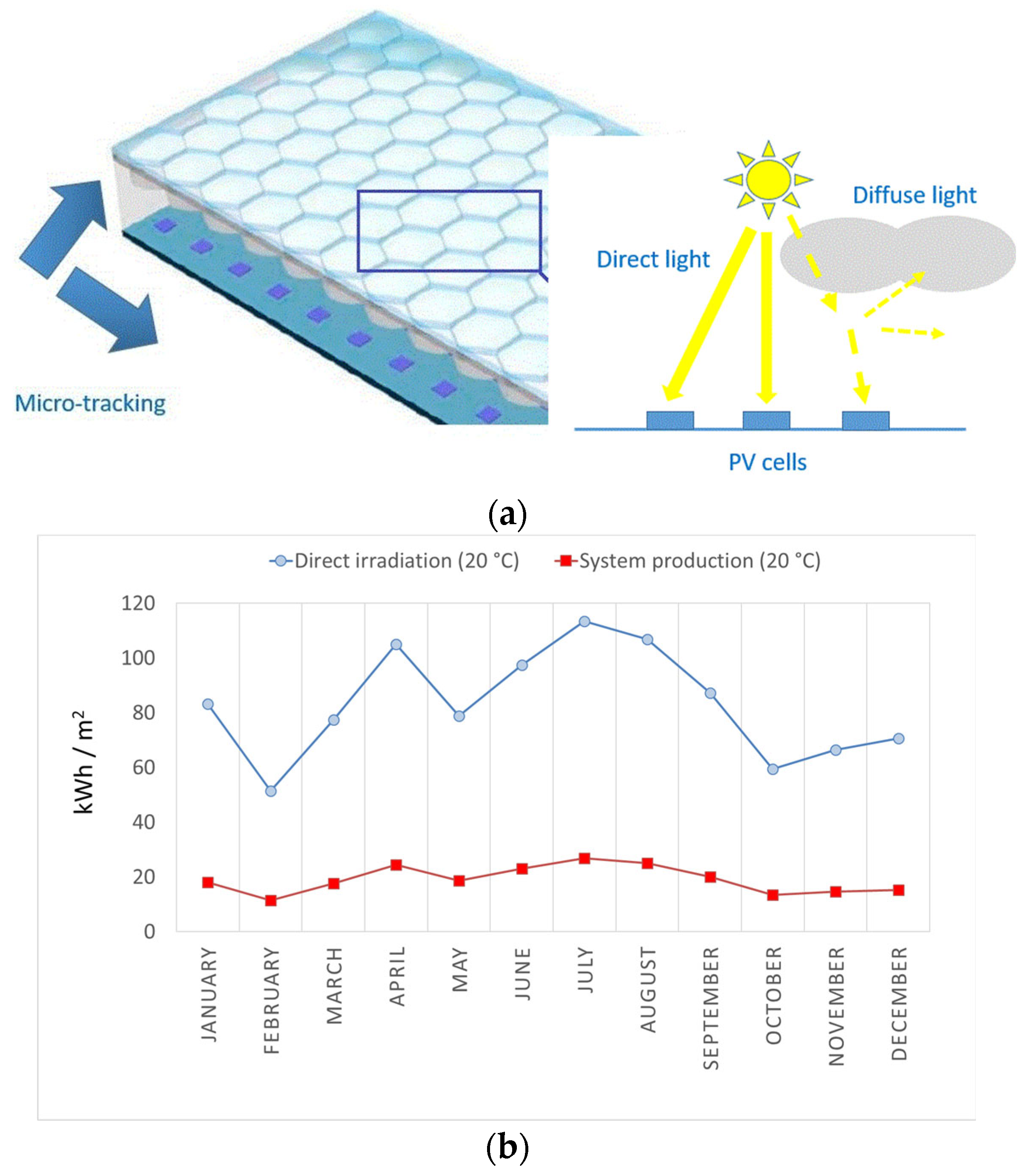
Figure 1a shows the CPV module, which was designed by Maestro et al. [14]. It has various layers as well as hexagonal lenses. The two optical layers (achromatic doublet) present different refractive indices and Abbe numbers, leading to minimisation of chromatic aberration in combination with the proper geometry of both layers. The two optical materials composing the doublet are as follows: polycarbonate (PC) and polymethyl methacrylate (PMMA). The solar-tracking device is based on micro-tracking technologies and tiny movements of the receiver. Diffuse irradiance, which is useless for producing electricity, enters the interior of the building and offers illumination. Figure 1b presents information about the output of the system and solar radiation. The case study refers to Barcelona. Details about the solar cells, energy simulation, optical design, etc., can be found in reference [14].
For the calculation of the electricity production/year, the following conditions were considered [14]:
-
The solar modules serve as an atrium of a building.
-
The orientation of the modules is south-facing, and their inclination is 20°.
-
The building of the case study is located in Barcelona (Catalonia, Spain).
-
The calculations have been based on typical-meteorological-year irradiation data (direct irradiance; Meteonorm).
-
The PV-cell electrical efficiency is 21.6%, and the geometrical concentration ratio is 12.5×.

2.2. Environmental LCA: Materials, Procedures and Methods

This section provides analytical information about the materials, the methods, and other aspects. A brief description of this information can be found in Appendix A (Table A1).
The proposed methodology is consistent with ISO standards [25,26]. The LCA model has been developed using SimaPro 9.4.0.1 [27] and ecoinvent 3 [28]. The following information was used for the chosen materials: cut-off, U; RER (the option RER has been chosen for all the materials/processes, except for steel, aluminium and the electric motor); GLO (the option GLO has been selected for steel, aluminium and the electric motor).
There are scenarios involving steel and aluminium recycling [29]. Information on the chosen materials (scenarios which involve recycling) is as follows: for steel, the option “steel with 59% recycled content” has been selected; for aluminium, the option “aluminium with 33% recycled content” has been chosen.
This LCA study aims to evaluate the eco-profile of a CPV system (the surface of one module is 1 m2 and the functional unit is 1 m2), including the additional components of this system. Another goal is to compare two options: (i) using an aluminium frame and (ii) using a steel frame. As for the functional unit “1 m2”, examples can be found in the literature on LCA of solar panels (solar thermal [30] and PV [31] panels). The stages of the life cycle included in this study are as follows: materials—material manufacturing; use phase; recycling of certain materials.
This analysis takes into account direct as well as indirect energy use. For the evaluation of these parameters, CED has been used [27,28]. Moreover, it considers greenhouse-gas emissions using IPCC-GWP (time horizon: 100 years) [27,28]. Additionally, it considers embodied energy as well as embodied carbon (recycling scenarios: source of data [29]).
Along with the previously described factors, in order to calculate the avoided environmental impacts (use phase), some additional methods/indicators have been considered [27,28]: ReCiPe, including midpoint as well as endpoint categories; water use (AWARE, which shows the amount of water that is available in a watershed after aquatic-ecosystem and human demands have been satisfied), water depletion index (according to Berger et al.) and a water scarcity indicator (based on the studies by Boulay et al. and Hoekstra et al.); freshwater eutrophication (according to Payen et al.); land use impacts on biodiversity (based on the study by Chaudhary et al.); USEtox (goal: to present information on human and eco-toxicological impacts); and EPS (which is related to environmental priority strategies and product design) [32]. The report [32] offers information about the studies by Berger et al., Boulay et al., Hoekstra et al., Payen et al. and Chaudhary et al.

2.3. Details About the Proposed Solar Systems

Two versions of the designed system have been examined. One of these two versions has an aluminium frame and the other has a steel frame. These two options have some features in common. The surface of one CPV module is 1 m2. The PV-cell surface is 0.0924 m2. The PV-cell type is laser grooved buried contact (LGBC) crystalline silicon. One module (1 m2) has 924 PV cells and 924 hexagonal concentrators. Both configurations have hexagonal concentrators and micro-tracking technologies. Further details can be found in reference [14].

2.4. Assumptions

It has been assumed that the useful life of the system is 15 years (pessimistic scenario). This assumption is supported by a recent publication by Lamnatou et al. [33]. Reference [33] addresses the life cycle eco-profile of an innovative CPV/thermal system suitable for building integration (the authors’ research group; University of Lleida, Spain).
With respect to the other materials/components, the PC lifespan is 10–20 years [34]. PMMA [35], aluminium [35], stainless steel [35] and motors [36] have long lifespans (longer than the useful life of the proposed solar system). Because of this, it has been assumed that, during the useful life of the proposed solar glazing (15 years), there is no replacement of the aforementioned parts of the installation, and this could be considered a logical assumption.
For the PV-impact calculations, the single crystal/silicon/Czochralski process (RER and cut-off options) [27,28] has been considered, i.e., the environmental impact of mono-Si PV cells has been used as a proxy for the LGBC solar cells because there is a lack of data for LGBC PV cells in official databases. In the scientific literature, little research has been conducted on the LCA of LGBC solar cells. LGBC cells have processing steps that are similar to traditional mono-Si cells; for this reason, several authors adopted mono-Si data as a reliable proxy. Zawadzki et al. [37] carried out a study on the eco-profile of PV modules with LGBC solar cells. For the life cycle calculations, the impact of monocrystalline PV cells was taken into account [37]. In the frame of the FP6 EU-funded project “Lab2Line,” screen-print and LGBC solar-cell processing techniques were studied. The goal was to produce PV cells (low cost; high efficiency) processed on large-area monocrystalline wafers [38].

2.5. Life Cycle Inventory

Details regarding the components/materials of the solar glazing for the two options (one with an aluminium frame and one with a steel frame) are shown in Table 1. In both cases, the data pertain to 1 m2 of PV-module surface. The material mass values presented in Table 1 are based on measurements from a physical prototype developed by the authors’ research group.

2.6. Environmental Payback Times: Equations

Considering scenarios with/without recycling of certain materials and two options (using aluminium frame; using steel frame), two types of environmental payback times, namely EPBT and GHG PBT, have been evaluated. The calculations have been based upon Equations (1) and (2):
E P B T = i m p a c t   o f   t h e   m a t e r i a l s   ( M J   p r i m a r y   e n e r g y ) o u t p u t   o f   t h e   s o l a r   s y s t e m   ( M J   p r i m a r y   e n e r g y y e a r )
G H G   P B T = i m p a c t   o f   t h e   m a t e r i a l s   ( k g   C O 2 . e q u i v a l e n t ) a v o i d e d   e m i s s i o n s   t h a n k s   t o   t h e   s o l a r   s y s t e m   ( k g   C O 2 . e q u i v a l e n t y e a r )
Definitions pertaining to the calculations are as follows: (1) For the evaluation of the EPBTs, PV-output conversion into primary energy has been effected considering the Spanish electricity grid [27,28]. The following are details about the CED of this electricity mix (the percentages show contributions to the total impact): 41% non-renewable (fossil); 39% non-renewable (nuclear); 2% renewable (biomass); 11% renewable (solar systems, wind power plants, etc.); 7% renewable (water-based systems) [27,28]. The numerator of Equation (1) includes energy demand/embodied energy related to material manufacturing (inputs), and the denominator is the annual output of the system (converted into primary energy); (2) For the evaluation of the GHG PBTs, the calculation of the prevented emissions (avoided emissions thanks to the solar system) has also been made using the electricity mix in Spain [27,28]. Details about the GWP of this electricity mix (the percentages show contributions to the total impact) are as follows: around 99% for GWP100-fossil; around 1% for GWP100-land transformation. The numerator of Equation (2) includes GWP/embodied carbon due to material manufacturing (inputs), and the denominator is the avoided impact/year (avoided CO2.eq emissions) thanks to the use of the solar system, instead of taking electricity from the Spanish grid. Figure 1b and Table 1 provide additional information related to the calculations of the above-mentioned environmental payback times.

3. Results and Discussion

3.1. Impacts of the Materials: Percentages Based on GWP and CED

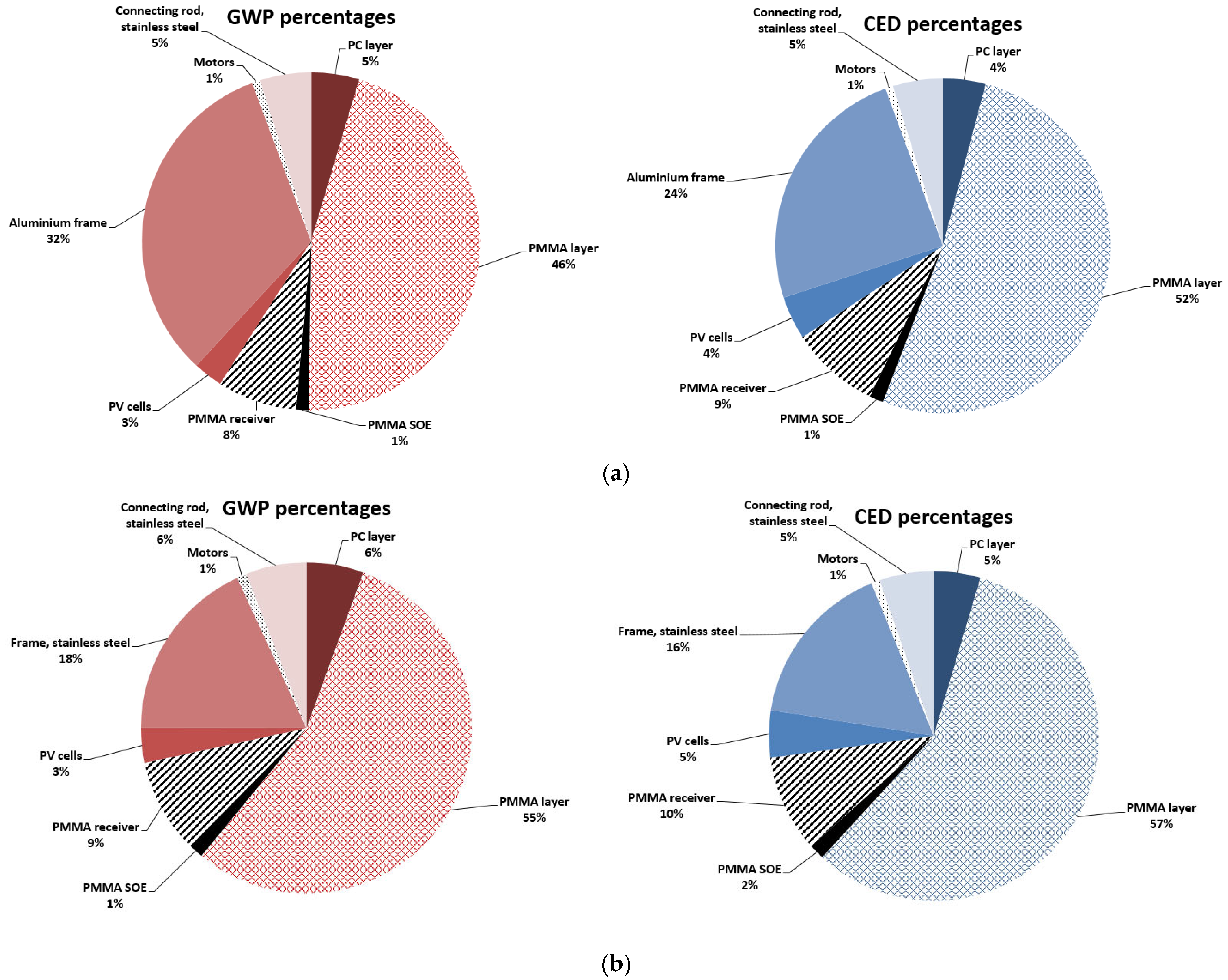
The GWP and CED percentages for both options are shown in Figure 2 (using an aluminium frame (Figure 2a); using a steel frame (Figure 2b)). The findings show that PMMA and the frames are the parts of the system with the biggest impacts on the environment. For example, the PMMA layer shows percentages which range from 46% (GWP; scenario: aluminium frame) to 57% (CED; scenario: steel frame). The steel frame shows lower GWP and CED percentages (18% and 16%, respectively) than the aluminium frame (32% and 24%, respectively). In both cases (option using an aluminium frame; option using a steel frame), the PV cells, the PC layer, the connecting rod and the motors have low GWP and CED percentages.
Critical discussion:
PMMA and the structural frames represent the primary environmental hotspots. Specifically, the PMMA layer dominates the environmental profile, contributing 46–55% to the GWP and 52–57% to the CED. Furthermore, the choice of framing material significantly influences the results. The steel frame demonstrates a lower environmental burden, exhibiting both GWP and CED shares below 20% compared to the aluminium-frame alternative. For both scenarios (aluminium frame; steel frame), the PV cells and the remaining auxiliary components have relatively low percentage contributions to both GWP and CED.
Based on references [39,40,41], a critical discussion regarding the future prospects and potential improvements to the eco-profile of the proposed solar system is provided in Section 3.5.

3.2. Impacts per m2 of Module Surface

The environmental impacts per m2 of PV-module surface are shown in Table 2. The values range from 341 to 507 kg CO2.eq/m2 and from 5660 to 7505 MJprim/m2. Recycling provides significant environmental-impact reductions: 167 and 70 kg CO2.eq/m2, 1845 and 1054 MJprim/m2, depending on the scenario. The results show that recycling is more beneficial for the system with an aluminium frame. Considering values from the literature on PV LCA [17,42], it can be said that the findings of the present analysis are logical.
Critical discussion:
The outcomes are beneficial because the proposed methodology would be employed in ecodesign. The goal should be to set minimum requirements for solar panels placed on the market. Enhancing both environmental performance and energy efficiency is a key element to controlling the effects on the environment, improving environmental sustainability and developing sustainable solar modules. Ecodesign could focus on minimising the environmental impact of the proposed solar system throughout its life cycle by improving material choices, manufacturing processes, durability and recyclability. Key areas may include reducing the environmental impacts during material manufacturing, promoting the use of more recoverable materials and developing economically viable recycling processes (end-of-life—disposal).
An interesting point is that the impact of the proposed solar module is similar to that of traditional PV modules (Table 2). Putting emphasis on material manufacturing, the environmental profile of the proposed BICPV system was benchmarked against building-integrated and building-added configurations. This comparison ensures that the solar system of the present study is evaluated not only as a functional building element but also against standard retrofitting PV modules. The key advantage of the PV technology of the present study is that these modules can serve as atriums, offering multiple benefits such as generation of clean electricity and improvement of daylighting. They have a dual functionality (energy-generating components and atriums) and use optics to concentrate sunlight for higher power, allowing diffuse light to pass through the modules indoors for illumination. In other words, they are multifunctional components that lower energy consumption, moving buildings towards net-zero-energy status.

3.3. EPBT and GHG PBT: Results of the Present LCA Study—Results of Other LCA Studies—Comparisons

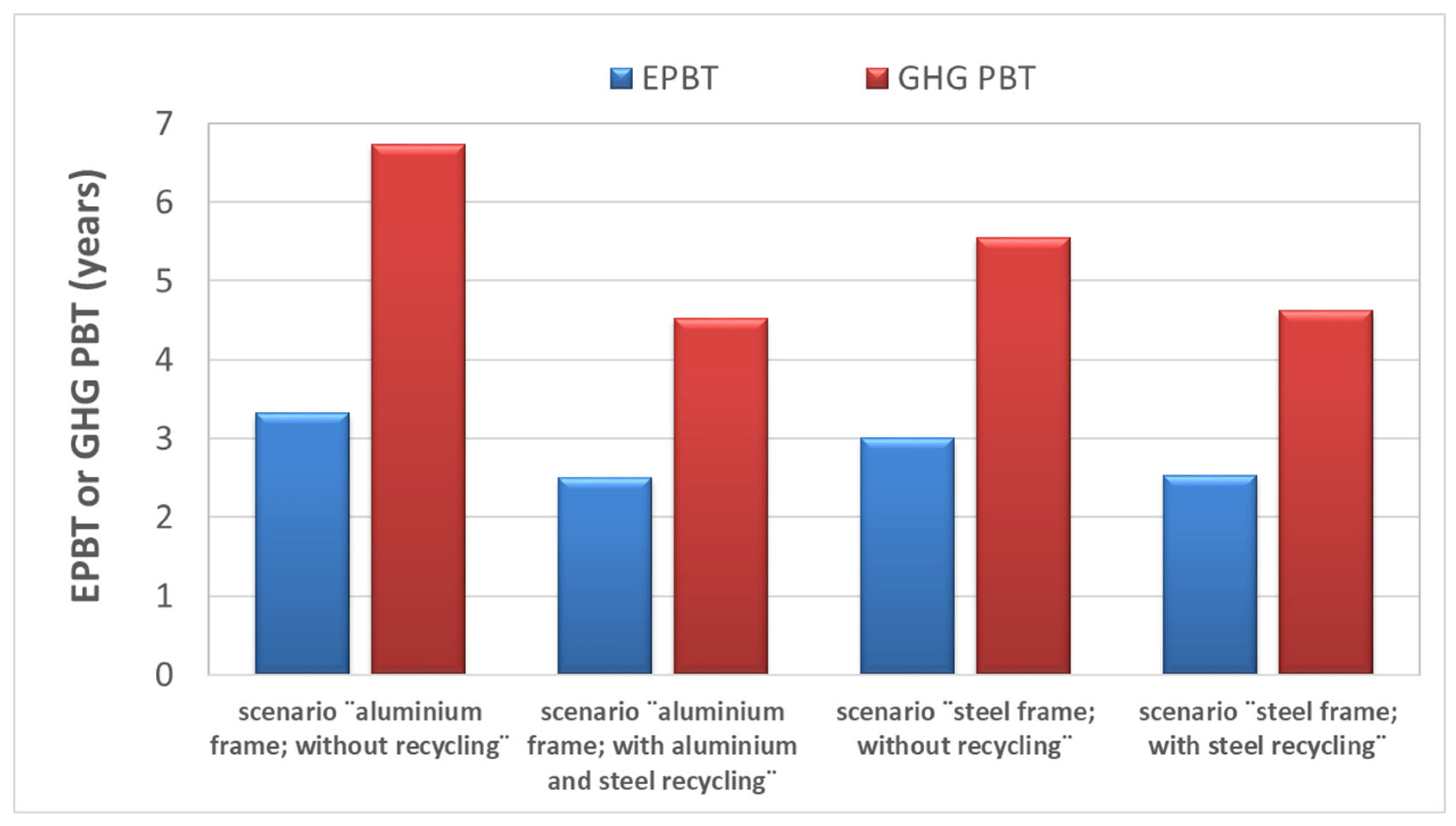
The results (Figure 3) reveal that EPBT values range from 2.5 to 3.3 years and GHG PBT values range from 4.5 to 6.7 years. Without considering recycling, the option “using aluminium frame” shows higher EPBT and GHG PBT values than the option “using steel frame”. In the case of the scenarios “with recycling”, both options (using aluminium frame; using steel frame) have almost the same EPBTs and GHG PBTs. The scenarios “with recycling” demonstrate significant decreases in EPBT and GHG PBT values (as high as 2.2 years). Additionally, the difference between EPBTs and GHG PBTs varies between 2.0 and 3.4 years (the values of GHG PBT are higher than those of EPBT).
Critical discussion:
The results of the present LCA study show environmental payback times shorter than the lifespan of the proposed solar system (pessimistic scenario: 15 years). This means that the proposed configurations are sustainable because they generate more energy than was used to produce them. Generally speaking, environmental payback times are critical metrics for evaluating the sustainability of a system which is based on renewable energy sources. For instance, EPBT is a critical energy metric and measures the number of years a system (e.g., a PV system) must operate in order to produce the same amount of energy used for its life cycle (raw material extraction, fabrication, etc.).
Environmental payback times and lifespan: results from the literature—comparisons
-
Reference [43]: PV/thermal (India); rooftop system: EPBT 4.9 years for amorphous-silicon solar cells; EPBT 1.48 years for copper-indium-diselenide solar cells.
-
Reference [44]: PV/thermal (air collectors; India); case study “wavy-plate collector” (polycrystalline solar cells): EPBT 1.9 years (option: energy yield).
-
Reference [37]: PVs with/without solar concentration; solar cells: LGBC; location: the UK; EPBT around 7–8 years.
-
Reference [18]: CPV modules appropriate for building integration; solar cells: monocrystalline silicon; Dublin: GHG PBT 3.3–4 years; Exeter: GHG PBT 4.7–5.7 years.
-
Reference [19]: BIPVs in Italy; lifespan: 25 years.
-
Reference [20]: This is a review paper about different types of BIPV systems. Environmental payback values lower than the lifespans of these building-integrated systems were reported.
-
Reference [45]: Floating, rooftop and ground-mounted PV panels (silicon-based solar cells); scenarios: lowland and high-altitude systems; Switzerland, EPBT (non-renewable) 1.4–3.6 years.
-
Reference [33]: The study [33] examined the life cycle eco-profile of BICPV/thermal modules. Regarding PV-cell impact, the calculations included silicon material (single crystal–Czochralski process) as well as additional components such as metallisation paste and ribbons. Each solar module had cylinders filled with fluids. Two configurations were evaluated: (i) with deionised water and (ii) with isopropyl alcohol. Regarding EPBT and GHG PBT, it was found that the water-based solar panels showed values between 2.7 years (EPBT; scenario: Barcelona/recycling) and 7.2 years (GHG PBT; scenario: Genoa/no recycling). The isopropyl-alcohol-based modules showed values which ranged between 3.4 years (EPBT; scenario: Barcelona/recycling) and 8.2 years (GHG PBT; scenario: Genoa/no recycling). In both cases (water-based panels; isopropyl-alcohol-based panels), the GHG PBT values were higher compared to the EPBT values. In most cases, there was a difference of one year (approximately) between the environmental payback times of the water-based modules and the ones of the isopropyl-alcohol-based modules. The water-based panels showed shorter environmental payback times and, considering all the scenarios, the environmental payback times were shorter than the solar system lifespan/useful life (15 years). Last but not least, the adoption of recycling offered reductions in the environmental payback times of 0.5–1.2 years.
By comparing the results of the present LCA study (environmental payback times) with those of other studies, it can be seen that the agreement is good; therefore, it can be claimed that the findings of the present analysis are reasonable and, as previously mentioned, the proposed PV technologies are environmentally competitive with the traditional ones.
Critical discussion:
From a general point of view, the results (present LCA and prior LCA studies on PV or PV/thermal technologies) demonstrate that, for solar modules, environmental payback times have significantly decreased over time due to technological advancements, often falling within a few years (these values are considerably lower than the lifespans of these solar systems). Emphasising sustainable energy production, these results show that solar panels provide green energy production, making them environmentally viable energy sources that generate much more energy than is required for their life cycle energy inputs.

3.4. Avoided Environmental Impacts: Use Phase

Results of the present study
The calculations have been made using the system output/year and the useful life of the system (scenario: 15 years [33]; this assumption can be characterised as pessimistic). Regarding lifespan output, two scenarios have been examined: (a) Scenario 1—there is no reduction in the output (i.e., every year the system has the same output) and (b) Scenario 2—there is a reduction in the output (0.7% reduction per year [18]: after the 2nd year of the use phase). The scenario assuming no reduction in BICPV output serves as an idealised baseline reference. The long-term impact of system degradation is realistically modelled in Scenario 2.
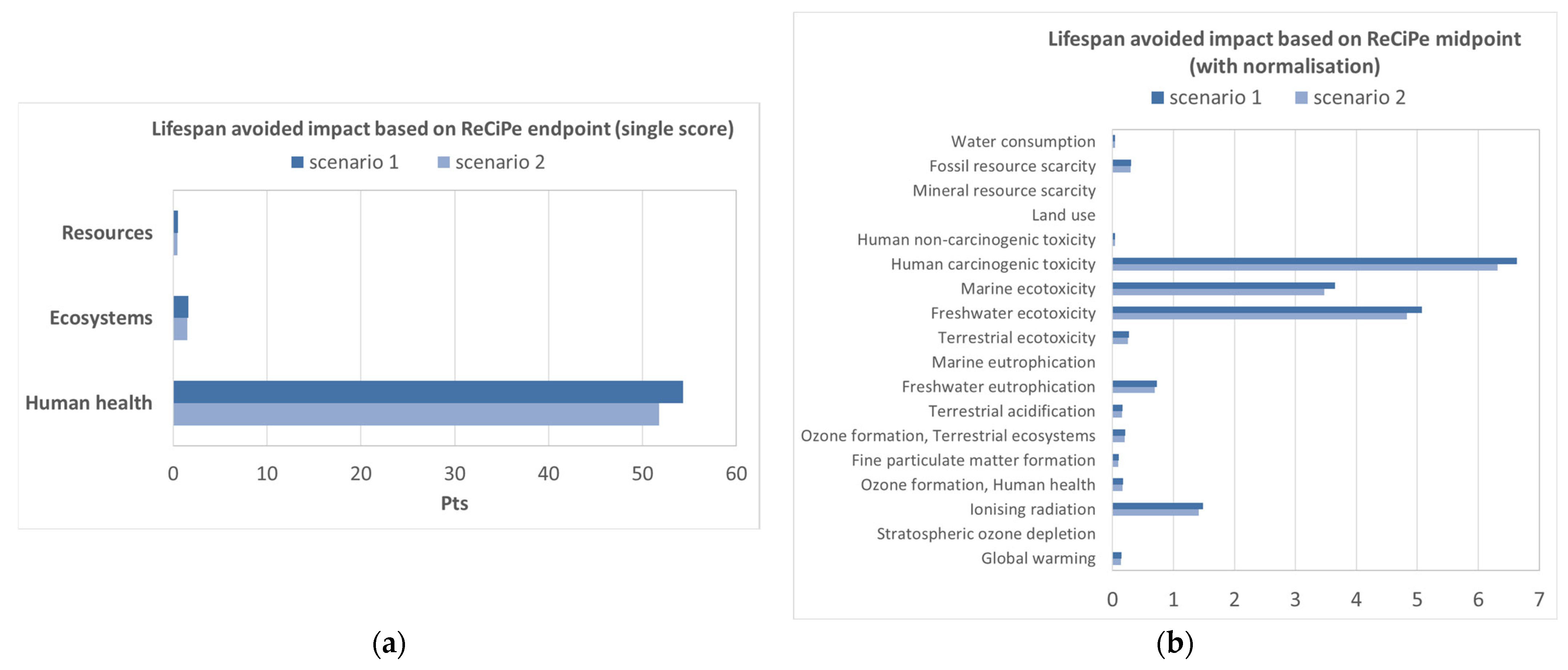
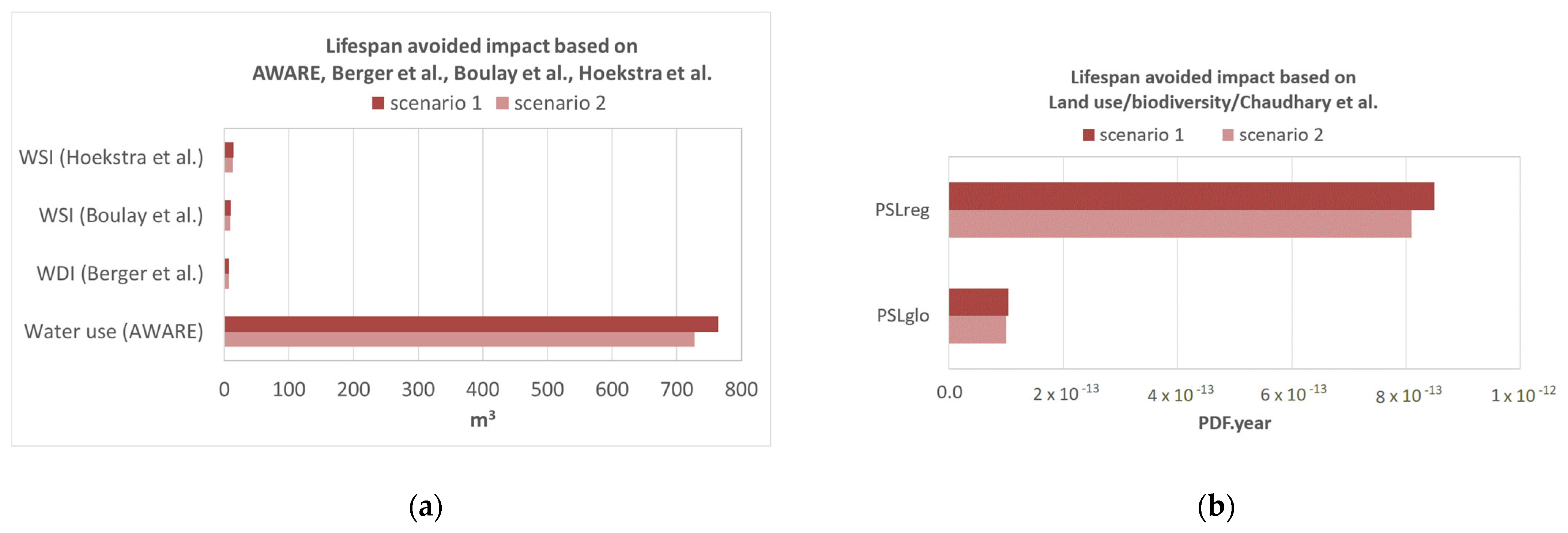
The avoided environmental impacts are shown in Figure 4: calculations according to ReCiPe endpoint/single-score (Figure 4a); calculations based on the ReCiPe midpoint/with normalisation (Figure 4b). Putting emphasis on impact categories related to human health and ecotoxicity, it can be noted that the proposed solar glazing provides a number of benefits. It is also interesting to note that there are additional advantages in terms of water use/depletion/scarcity (Figure 5a) and biodiversity (Figure 5b). Concerning the averted effects, further information is provided in Table 3. It can be said that this solar glazing provides important environmental advantages, such as the elimination of the impacts on human health, ecosystems, water quality/quantity and biodiversity, as well as mitigation of impacts due to greenhouse-gas emissions, energy inputs and the use of natural resources.
Critical discussion and results from the literature on PV LCA
Focusing on Scenarios 1 and 2 (Figure 4 and Figure 5; Table 3), it can be noted that there are no striking differences between the two options. This reveals very similar outcomes, meaning that the variable (reduction in output due to degradation, thermal stress, etc.) does not significantly alter the results (avoided impacts during the use phase).
Overall, the results demonstrate that, during the use phase, the proposed solar panels avoid significant environmental impacts by generating electricity without producing toxic chemicals like those related to fossil fuels. They also avoid environmental issues such as mining for coal and habitat destruction (for example, due to fossil-fuel infrastructures and oil spills).
In the literature on PV LCA, there are studies that presented avoided impacts, focusing on the potential for CO2.eq or CO2 mitigation. By way of illustration, Lamnatou et al. [18] evaluated the eco-profile of a BICPV system. The system had 43 modules which corresponded to 3.86 m2 net PV surface and 10.53 m2 aperture area. In the case of Barcelona and Madrid (configuration without reflective film), the results showed around 800 kg CO2.eq/year (avoided emissions). Different cities/countries were examined. The results were influenced by the electricity mix, which was used as reference in each case. The potential for PV CO2 mitigation was also studied by Gaiddon and Jedliczka [46] (different cities/countries), supporting the above-mentioned statement about the influence of the electricity mix.

3.5. Future Prospects

Future studies could address the following topics:
One suggestion with regard to alternative materials (in general) is to fabricate the proposed solar glazing using materials of low environmental impact (in lieu of PMMA). The analysis of this LCA study has been based on the materials of solar modules intended for experimental purposes (the authors’ research group; University of Lleida, in Spain). Enhancement could be achieved using more environmentally friendly materials. The goal should be to reduce the environmental footprint of the frame as well as the impact of the PMMA components.
Major environmental issues are caused by the use of PMMA, but this material can be transformed into new products, i.e., there are strategies to make PMMA components more ecologically sustainable. However, suitable techniques should be adopted, such as waste reduction, material reuse, different recycling options, etc. In the case of PMMA, scrap is a source of waste and has negative impacts (from a financial perspective; from an ecological perspective), but there are ways to eliminate these impacts [39]. Overall, it can be said that future improvements to the PMMA environmental profile could focus on enhancing its recycling to recover certain compounds, increasing the use of bio-based feedstock materials during material manufacturing and developing more energy-efficient processes. These efforts should aim to reduce PMMA fossil-fuel dependence, minimise waste materials, lower energy consumption, extend the lifespan of this material and promote the circular economy.
As for stainless steel, it is recyclable. The components made of stainless steel could be recycled, which would benefit the environment [40]. Stainless steel has advantages such as long lifespan (i.e., the components made of stainless steel last a long time) and the possibility to recover certain alloying elements [40]. From a critical point of view, future improvements for the environmental performance of stainless steel could focus on enhancing energy efficiency and reducing the carbon footprint during material manufacturing through the adoption of renewable energy sources and carbon-capture technologies. Another idea is to enhance stainless-steel circularity by improving scrap sorting, enabling closed-loop recycling and developing low-carbon grades.
With respect to aluminium, this material encompasses various environmental issues (for example, during manufacturing). It is, therefore, necessary to create effective production methods. The primary industry is a major cause of air pollutants for several reasons, for instance, electrolysis. With respect to the primary industry, one option to improve the environmental profile of aluminium fabrication is to design anodes using ecologically sustainable materials and promote the use of secondary metal [41]. Overall, future improvements to aluminium environmental performance could focus on reducing the energy-intensive primary production of this material by using renewable energy sources and adopting inert-anode technologies to eliminate carbon emissions during electrolysis processes. Another strategy is to increase the rate and efficiency of aluminium recycling. Generally speaking, the goal should be to lower the carbon footprint of the value chain of this material and support the demand for low-carbon aluminium in the green economy.
Muteri et al. [47] examined the environmental profile of a BICPV (smart window), underlining how these solar systems contribute to reducing building energy demand for heating, cooling and lighting. It was noted that while these technologies have higher environmental impacts per kWh than conventional PV panels due to lower efficiency, their smart/multifunctional design provides indirect benefits. The study [47] serves as a bridge between environmental LCA and architectural engineering, shifting the focus from simple energy efficiency to multi-functional sustainability.
Overall, it can be said that future research in the field of BICPVs could prioritise the dual-functional nature of these PV modules, recognising that their value extends beyond simple energy generation. Unlike conventional PVs, BICPVs are integrated into the building envelope and provide benefits. Future studies may focus on quantifying the avoided environmental impacts gained by substituting conventional construction materials with these energy-generating elements, particularly through the use of recycled materials to reduce material manufacturing impacts. Another idea is to focus on the energy benefits for buildings and investigate polymer recycling in next-generation BICPV designs. By optimising energy-saving potential and reducing environmental impacts, BICPVs could be a valuable step towards zero-energy buildings.

4. Conclusions

Considering the gaps in the literature on BICPV LCA, the purpose of this study is to assess the eco-profile of an innovative BICPV system (solar glazing—atrium) with two optical materials and micro-tracking, extending the previous work on the design/performance of this solar system. The proposed modules are innovative because they integrate avant-garde technologies to achieve effective daylighting control, offering valuable services towards zero-energy buildings.
Furthermore, this study advances the current state of the art by developing a multi-indicator LCA model that goes beyond standard carbon-based and energy-based models, incorporating a whole host of metrics and impact categories. Additionally, the LCA model includes recycling scenarios (materials: aluminium; steel).
The case study has been based on a building in Barcelona. Two options have been examined: (i) using an aluminium frame and (ii) using a steel frame.
Regarding CED and GWP, the results demonstrate that PMMA and the frames are the parts of the system with the highest environmental impacts. As for the impacts per m2 of PV-module surface, the values range from 341 to 507 kg CO2.eq/m2 and from 5660 to 7505 MJprim/m2. Recycling offers opportunities for substantial mitigation of these environmental impacts. Concerning environmental payback times, EPBTs vary between 2.5 and 3.3 years, and GHG PBTs range from 4.5 to 6.7 years. Recycling offers considerable reductions in EPBTs and GHG PBTs (as high as 2.2 years). The results about the averted environmental impacts thanks to the use of electricity produced by the proposed BICPV, instead of using electricity from the national grid (electricity grid) in Spain, show that this solar glazing provides substantial environmental benefits, such as the elimination of the impacts on human health/ecosystems and the mitigation of impacts due to the use of natural resources.
Comparisons with other LCA studies on traditional PV modules show that the proposed solar modules are competitive (from an environmental point of view) with conventional PVs. An additional advantage of the proposed PV modules is that they can serve as atriums, providing multifunctional solutions that optimise energy performance, lighting conditions and architectural design (important features towards net-zero-energy buildings). A key advantage of the proposed solar modules is their ability to provide effective daylighting control.
With the aim of improving the eco-profile of the proposed solar glazing, future studies could address the following topics: energy benefits for buildings; use of alternative/eco-friendly materials; improvement of certain manufacturing processes; and adoption/promotion of recycling.

Author Contributions

Conceptualisation, C.L., S.M. and D.C.; methodology, C.L., S.M. and D.C.; software, C.L.; validation, C.L., S.M. and D.C.; formal analysis, C.L. and S.M.; investigation, C.L., S.M. and D.C.; writing—original draft preparation, C.L.; writing—review and editing, C.L., S.M. and D.C.; visualisation, C.L.; supervision, D.C.; project administration, D.C. All authors have read and agreed to the published version of the manuscript.

Funding

The authors would like to thank the Ministerio de Ciencia e Innovación of Spain MCIN/AEI/10.13039/501100011033 for the funding (grant reference: PID2019-111536RB-I00; TED2021-132843B-I00). The research of S. Maestro was supported by the Secretaría General de Universidades del Ministerio de Universidades of Spain (grant FPU20/01189) and the Col·legi d’Enginyers Industrials de Catalunya (Beca Tesi Doctoral 2022 award). D. Chemisana thanks Institució Catalana de Recerca i Estudis Avançats (ICREA) for the ICREA Acadèmia award. Chr. Lamnatou is a Serra Húnter fellow. Furthermore, this research was supported by the Generalitat de Catalunya (2021 SGR 01618).

Data Availability Statement

Data are contained within the article.

Conflicts of Interest

The authors declare no conflicts of interest.

Abbreviations

The following abbreviations are used in this manuscript:
BICPVBuilding-Integrated Concentrating Photovoltaic
BICPV/thermalBuilding-Integrated Concentrating Photovoltaic/thermal
CEDCumulative Energy Demand
CO2.eqCO2.equivalent
CPVConcentrating Photovoltaic
DALYDisability-Adjusted Life Year
EPBTEnergy Payback Time
GHG PBTGreenhouse-Gas Payback Time
GWPGlobal Warming Potential
LCALife Cycle Assessment
LGBCLaser Grooved Buried Contact
MJprimMJprimary
PCPolycarbonate
PDFPotentially Disappeared Fraction of Species
PMMAPolymethyl Methacrylate
PSLgloPotential Species Loss (global indicator)
PSLregPotential Species Loss (regional indicator)
PtsPoints
PVPhotovoltaic
SOESecondary Optical Element
WDIWater Depletion Index
WSIWater Scarcity Indicator

Appendix A

Table A1. The basic characteristics of the proposed BICPV system and summary of the main assumptions and the key data used in this study.
Technical Characteristics and Functionality—Inputs, Outputs, etc.Source of Information or Justification of This Choice
Two optical materials: PC and PMMA; micro-trackers; achromatic doubletsA system developed by the authors’ research group (Maestro et al. [14])
Configuration with aluminium frame vs. configuration with steel frameTo examine the effect of the frame material
Production of electricity and illumination of a building (atrium)[14]
Case study: a building in Barcelona (a typical residential building)[14]
Direct irradiation (20 °C): 998 kWh/m2 (annual)
System production (20 °C): 229 kWh/m2 (annual)
Typical-meteorological-year irradiation data (meteonorm)
PV-cell electrical efficiency = 21.6%
Geometrical concentration ratio = 12.5×
[14]
The orientation of the modules is south-facing, and their inclination is 20°[14]
Materials: cut-off, U; RER (the option RER has been chosen for all the materials/processes, except for steel, aluminium and the electric motor)SimaPro 9.4.0.1 [27] and ecoinvent 3 [28]
The option GLO has been selected for steel, aluminium and the electric motorSimaPro 9.4.0.1 [27] and ecoinvent 3 [28]
Scenarios involving steel and aluminium recycling: steel with 59% recycled content; aluminium with 33% recycled contentEmbodied energy; embodied carbon [29]
Functional unit = 1 m2 of solar module[30,31]
Surface of one CPV module (1 m2) → PV-cell surface = 0.0924 m2[14]
One module (1 m2) has 924 PV cells as well as 924 hexagonal concentrators[14]
The real system: LGBC solar cells
The LCA model: single crystal/silicon/Czochralski process (RER and cut-off options)
Data from [27,28]; references to support this assumption [37,38]
Lifespan of the system: 15 years (pessimistic scenario)[33]
Reduction in PV output during use phaseScenario 1: no reduction; Scenario 2: 0.7% reduction [18] after the 1st year
PC lifespan = 10–20 years[34]
PMMA [35], aluminium [35], stainless steel [35] and motors [36] have long lifespans (longer in comparison to the useful life of the proposed system)[35,36]
Materials/components—mass: two configurationsTable 1 of the present study
Information about the environmental payback times: equations and explanationsSection 2.6 of the present study
Boundaries: material manufacturing and use phaseThe present study

References

  1. Wang, B.; Xu, Y.; Wang, H.; Zhang, X.; Chen, Y.; Tang, R.; Yan, A.; Zhang, M.; He, Y. Utilizing a three-zone control model of adaptive concentrating photovoltaic facade to enhance visual comfort and energy benefits. Energy Build. 2025, 345, 116125. [Google Scholar] [CrossRef]
  2. European Commission. Energy Performance of Buildings Directive. Available online: https://energy.ec.europa.eu/topics/energy-efficiency/energy-performance-buildings/energy-performance-buildings-directive_en (accessed on 26 April 2026).
  3. Poulsen, P.B.; Thorsteinsson, S.; Jakobsen, M.L.; Hanson, S.G.; Jensen, A.K. Building Integrated Concentrator PV Window; Feasibility Study. ForskEL 12.213—BICPV. Final Report; DTU Fotonik, AKJ Inventions: Glostrup, Denmark, 2015. [Google Scholar]
  4. Ceballos, M.A.; Pérez-Higueras, P.J.; Fernández, E.F.; Almonacid, F. Tracking-Integrated CPV Technology: State-of-the-Art and Classification. Energies 2023, 16, 5605. [Google Scholar] [CrossRef]
  5. Li, J.; Zhang, W.; He, B.; Xie, L.; Hao, X.; Mallick, T.; Shanks, K.; Chen, M.; Li, Z. Experimental study on the comprehensive performance of building curtain wall integrated compound parabolic concentrating photovoltaic. Energy 2021, 227, 120507. [Google Scholar] [CrossRef]
  6. Sellami, N.; Mallick, T.K. Optical characterisation and optimisation of a static Window Integrated Concentrating Photovoltaic system. Sol. Energy 2013, 91, 273–282. [Google Scholar] [CrossRef]
  7. Liang, S.; Zheng, H.; Liu, S.; Ma, X. Optical design and validation of a solar concentrating photovoltaic-thermal (CPV-T) module for building louvers. Energy 2022, 239, 122256. [Google Scholar] [CrossRef]
  8. Novelli, N.; Phillips, K.; Shultz, J.; Derby, M.M.; Salvas, R.; Craft, J.; Stark, P.; Jensen, M.; Derby, S.; Dyson, A. Experimental investigation of a building-integrated, transparent, concentrating photovoltaic and thermal collector. Renew. Energy 2021, 176, 617–634. [Google Scholar] [CrossRef]
  9. Piratheepan, M.; Anderson, T.N. Performance of a building integrated photovoltaic/thermal concentrator for facade applications. Sol. Energy 2017, 153, 562–573. [Google Scholar] [CrossRef]
  10. Nardin, G.; Domínguez, C.; Aguilar, Á.F.; Anglade, L.; Duchemin, M.; Schuppisser, D.; Gerlich, F.; Ackermann, M.; Coulot, L.; Cuénod, B.; et al. Industrialization of hybrid Si/III–V and translucent planar micro-tracking modules. Prog. Photovolt. Res. Appl. 2021, 29, 819–834. [Google Scholar] [CrossRef]
  11. Lloyd, J.; Pavilonis, M.; Gladden, C.; Casper, C.; Schneider, K.; McMahon, W.; Kozodoy, P. Performance of a prototype stationary catadioptric concentrating photovoltaic module. Opt. Express 2018, 26, A413–A419. [Google Scholar] [CrossRef]
  12. Vu, N.H.; Shin, S. Flat Concentrator Photovoltaic System with Lateral Displacement Tracking for Residential Rooftops. Energies 2018, 11, 114. [Google Scholar] [CrossRef]
  13. Jouanneau, C.; Denain, M.; Guernion, L.; Bidaud, T.; Kouame, K.; Weiss, M.; Turala, A.; Danovitch, D.; Bryche, J.F.; Darnon, M.; et al. Design, manufacture and characterization of compact optics for micro-CPV. EPJ Photovolt. 2025, 16, 27. [Google Scholar] [CrossRef]
  14. Maestro, S.; Chemisana, D.; Moreno, A. Design and performance evaluation of a Micro-CPV system for building integration applications. Sustain. Energy Technol. Assess. 2024, 69, 103898. [Google Scholar] [CrossRef]
  15. Vallerotto, G.; Victoria, M.; Jost, N.; Askins, S.; Domínguez, C.; Herrero, R.; Anton, I. Comparison of achromatic doublet on glass Fresnel lenses for concentrator photovoltaics. Opt. Express 2021, 29, 20601–20616. [Google Scholar] [CrossRef]
  16. Menoufi, K.; Chemisana, D.; Rosell, J.I. Life cycle assessment of a building integrated concentrated photovoltaic scheme. Appl. Energy 2013, 111, 505–514. [Google Scholar] [CrossRef]
  17. Lamnatou, C.; Smyth, M.; Chemisana, D. Building-integrated photovoltaic/thermal (BIPVT): LCA of a façade-integrated prototype and issues about human health, ecosystems, resources. Sci. Total Environ. 2019, 660, 1576–1592. [Google Scholar] [CrossRef] [PubMed]
  18. Lamnatou, C.; Baig, H.; Chemisana, D.; Mallick, T.K. Life cycle energy analysis and embodied carbon of a linear dielectric-based concentrating photovoltaic appropriate for building-integrated applications. Energy Build. 2015, 107, 366–375. [Google Scholar] [CrossRef]
  19. Luu, L.Q.; Cellura, M.; Guarino, F.; Longo, S. Eco-design of emerging BIPV modules based on LCA and LCC. Energy 2025, 333, 137500. [Google Scholar] [CrossRef]
  20. Yan, Y.; Xiang, C. Life cycle carbon footprint and sustainability assessment of building-integrated photovoltaics: A comparative review of technologies and applications. Energy Build. 2026, 350, 116678. [Google Scholar] [CrossRef]
  21. Longo, S.; Rincione, R.; Cellura, M.; Rossi, F.; Sinicropi, A.; Parisi, M.L. Life cycle assessment of concentrating solar power systems and concentrating photovoltaic systems: A review. Energy Rep. 2025, 14, 4526–4539. [Google Scholar] [CrossRef]
  22. Cellura, M.; Luu, L.Q.; Guarino, F.; Longo, S. A review on life cycle environmental impacts of emerging solar cells. Sci. Total Environ. 2024, 908, 168019. [Google Scholar] [CrossRef]
  23. Tripanagnostopoulos, Y.; Souliotis, M.; Battisti, R.; Corrado, A. Performance, Cost and Life-cycle Assessment Study of Hybrid PVT/AIR Solar Systems. Prog. Photovolt. Res. Appl. 2006, 14, 65–76. [Google Scholar] [CrossRef]
  24. Talpur, B.D.; Cannavale, A.; Liuzzi, S.; Rubino, S.; Martellotta, F. Towards sustainable smart window design: Life cycle assessment of innovative electrochromic devices. Energy Build. 2026, 359, 117290. [Google Scholar] [CrossRef]
  25. ISO 14040:2006; Environmental Management, Life Cycle Assessment, Principles and Framework. ISO: Geneva, Switzerland.
  26. ISO 14044:2006; Environmental Management, Life Cycle Assessment, Requirements and Guidelines. ISO: Geneva, Switzerland.
  27. SimaPro. Available online: https://www.simapro.com (accessed on 26 April 2026).
  28. Ecoinvent. Available online: https://www.ecoinvent.org (accessed on 26 April 2026).
  29. Hammond, G.; Jones, C. Inventory of Carbon and Energy (ICE); Department of Mechanical Engineering, University of Bath: Bath, UK, 2011. [Google Scholar]
  30. Carlsson, B.; Persson, H.; Meir, M.; Rekstad, J. A total cost perspective on use of polymeric materials in solar collectors—Importance of environmental performance on suitability. Appl. Energy 2014, 125, 10–20. [Google Scholar] [CrossRef]
  31. Singh, S.; Kajal, P.; Dhar, A.; Mathews, N.; Boix, P.P.; Powar, S. Reduced global warming potential in carbon-based perovskite solar modules: Cradle-to-gate life cycle analysis. J. Clean. Prod. 2023, 426, 139136. [Google Scholar] [CrossRef]
  32. Database & Support Team, PRé Sustainability. SimaPro Database Manual, Methods Library; PRé Sustainability: Amersfoort, The Netherlands, 2022. [Google Scholar]
  33. Lamnatou, C.; Moreno, A.; Riverola, A.; Maestro, S.; Chemisana, D. Environmental life-cycle assessment of building-integrated concentrating photovoltaic/thermal systems consisting of cylinders filled with dielectric fluids. Renew. Energy 2025, 255, 123818. [Google Scholar] [CrossRef]
  34. Available online: www.quandaplastic.com/how-long-do-pc-polycarbonate-sheets-last/ (accessed on 26 April 2026).
  35. Berge, B. The Ecology of Building Materials, 2nd ed.; Butters, C.; Henley, F., Translators; Architectural Press, Elsevier: Oxford, UK; Burlington, MA, USA, 2009. [Google Scholar]
  36. Hasanuzzaman, M.; Rahim, N.A.; Saidur, R. Analysis of Energy Savings for Rewinding and Replacement of Industrial Motor. In Proceedings of the 2010 IEEE International Conference on Power and Energy, Kuala Lumpur, Malaysia, 29 November–1 December 2010. [Google Scholar]
  37. Zawadzki, P.; Muhammad-Sukki, F.; Abu-Bakar, S.H.; Bani, N.A.; Abubakar Mas’ud, A.; Ardila-Rey, J.A.; Munir, A.B. Life Cycle Assessment of a Rotationally Asymmetrical Compound Parabolic Concentrator (RACPC). Sustainability 2020, 12, 4750. [Google Scholar] [CrossRef]
  38. Serenelli, L.; De Iuliis, S.; Izzi, M.; Tucci, M.; Salza, E.; Pirozzi, L.; Cole, A.; Brown, L.M.; Devenport, S.; Drew, K.; et al. Screen printing in laser grooved buried contact solar cells: The Lab2Line hybrid processes. In Proceedings of the 25th European PV Solar Energy Conference, Valencia, Spain, 6–10 September 2010. [Google Scholar]
  39. Charmondusit, K.; Seeluangsawat, L. Recycling of poly(methyl methacrylate) scrap in the styrene–methyl methacrylate copolymer cast sheet process. Resour. Conserv. Recycl. 2009, 54, 97–103. [Google Scholar] [CrossRef]
  40. British Stainless Steel Association. Available online: https://bssa.org.uk/bssa_articles/environmental-aspects-of-stainless-steel/ (accessed on 26 April 2026).
  41. Brough, D.; Jouhara, H. The aluminium industry: A review on state-of-the-art technologies, environmental impacts and possibilities for waste heat recovery. Int. J. Thermofluids 2020, 1–2, 100007. [Google Scholar] [CrossRef]
  42. Lamnatou, C.; Lecoeuvre, B.; Chemisana, D.; Cristofari, C.; Canaletti, J.L. Concentrating photovoltaic/thermal system with thermal and electricity storage: CO2.eq emissions and multiple environmental indicators. J. Clean. Prod. 2018, 192, 376–389. [Google Scholar] [CrossRef]
  43. Rao, V.T.; Sekhar, Y.R.; Mahesh, H.; Muraleedharan, A.K.; Charles, D.; Aljuraide, N.I.; Ibrahim, A.M.M.; Helal, M.; Galal, A.M.; Sami, R.; et al. Life Cycle Analysis of Thin-Film Photovoltaic Thermal Systems for Different Tropical Regions. Sustainability 2022, 14, 14209. [Google Scholar] [CrossRef]
  44. Jha, P.; Mondol, J.D.; Das, B.; Gupta, R. Energy metrics assessment of a photovoltaic thermal air collector (PVTAC): A comparison between flat and wavy collector. Energy Sources Part A Recovery Util. Environ. Eff. 2024, 46, 15052–15070. [Google Scholar] [CrossRef]
  45. Frehner, A.; Stucki, M.; Itten, R. Are alpine floatovoltaics the way Forward? Life-Cycle environmental impacts and energy payback time of the Worlds’ first High-Altitude floating solar power plant. Sustain. Energy Technol. Assess. 2024, 68, 103880. [Google Scholar] [CrossRef]
  46. Gaiddon, B.; Jedliczka, M. Compared Assessment of Selected Environmental Indicators of Photovoltaic Electricity in OECD Cities; International Energy Agency, Photovoltaic Power Systems Programme, IEA PVPS Task 10, Activity 4.4, Report IEA-PVPS T10-01:2006; IEA: Paris, France, 2006. [Google Scholar]
  47. Muteri, V.; Longo, S.; Traverso, M.; Palumbo, E.; Bua, L.; Cellura, M.; Testa, D.; Guarino, F. Life Cycle Assessment of Luminescent Solar Concentrators Integrated into a Smart Window. Energies 2023, 16, 1869. [Google Scholar] [CrossRef]
Figure 1. The CPV module: (a) optical layers; working principle; (b) electricity production (annual) and direct irradiation (annual; Barcelona, Catalonia, Spain).
Energies 19 02578 g001
Figure 2. GWP and CED percentages (fabrication of the materials): (a) option using aluminium frame, (b) option using steel frame. SOE stands for secondary optical element. Due to the effects of rounding decimal points, the cumulative total of the chart components may deviate slightly from 100%. This is a standard statistical occurrence and does not affect the accuracy of the underlying dataset.
Energies 19 02578 g002
Figure 3. EPBT and GHG PBT values. Different scenarios: aluminium frame/without recycling; aluminium frame/with aluminium and steel recycling; steel frame/without recycling; steel frame/with steel recycling.
Energies 19 02578 g003
Figure 4. Avoided environmental impacts (considering the useful life of the system; Scenario 1; Scenario 2) based on: (a) ReCiPe endpoint (single score: Pts), (b) ReCiPe midpoint (with normalisation).
Energies 19 02578 g004
Figure 5. Avoided environmental impacts (considering the useful life of the system; Scenario 1; Scenario 2) based on: (a) AWARE (water use), Berger et al. (WDI stands for water depletion index), Boulay et al. (WSI means water scarcity indicator), Hoekstra et al. (WSI), m3; (b) land-use impacts on biodiversity, Chaudhary et al. (PDF.year). PDF stands for potentially disappeared fraction of species. PSL means potential species loss (PSLreg: regional indicator; PSLglo: global indicator). The report [32] offers information about the studies by Berger et al., Boulay et al., Hoekstra et al. and Chaudhary et al.
Energies 19 02578 g005
Table 1. The materials of the designed BICPV system: module (1 m2) and additional components: option using aluminium frame and option using steel frame.
Components/MaterialsMaterialsMass (kg)
Option using aluminium frame
PC layerPC2.88
PMMA layerPMMA26.74
PMMA secondary optical elementPMMA0.70
PMMA receiverPMMA4.46
PV cellsSilicon, single crystal0.14
Aluminium frameAluminium 8.58
MotorsCopper, aluminium, etc.0.44
Connecting rod: stainless steelStainless steel5.08
Option using steel frame
PC layerPC2.88
PMMA layerPMMA26.74
PMMA secondary optical elementPMMA0.70
PMMA receiverPMMA4.46
PV cellsSilicon, single crystal0.14
FrameStainless steel15.52
MotorsCopper, aluminium, etc.0.44
Connecting rod: stainless steelStainless steel5.08
Table 2. Impacts per m2 of module surface. Results: present analysis and studies [17,42].
StudyType of PV ModuleType of PV CellsImpact:
kg CO2.eq/m2
Impact:
MJprim./m2
Present study BICPV (scenario ¨aluminium frame; without recycling¨)LGBC (for the calculations: monocrystalline silicon)5077505
Present study BICPV (scenario ¨aluminium frame; with aluminium and steel recycling¨)LGBC (for the calculations: monocrystalline silicon)3415660
Present study BICPV (scenario ¨steel frame; without recycling¨)LGBC (for the calculations: monocrystalline silicon)4186777
Present study BICPV (scenario ¨steel frame; with steel recycling¨)LGBC (for the calculations: monocrystalline silicon)3485723
[42]Building-added PV/thermal (scenario ¨without batteries; with storage tank¨)Polycrystalline silicon 5206050
[42]Building-added PV/thermal (scenario ¨without batteries; without storage tank¨)Polycrystalline silicon 4905670
[17]BIPV/thermal (façade-integrated prototype; scenario ¨primary materials¨)Monocrystalline silicon 3404920
Table 3. Avoided environmental impacts (considering the useful life of the system; Scenario 1; Scenario 2) based on GWP, CED, ReCiPe endpoint (with characterisation), freshwater eutrophication (Payen et al.), USEtox and EPS. The report [32] offers information about the study by Payen et al.
Methods and Indicators Results: Avoided Environmental Impacts (Lifespan)—Scenario 1 Results: Avoided Environmental Impacts (Lifespan)—Scenario 2
GWP1130 kg CO2.eq1076 kg CO2.eq
CED33,880 MJprim32,269 MJprim
ReCiPe endpoint (with characterisation)0.0033 DALY0.0031 DALY
ReCiPe endpoint (with characterisation)5.9 × 10⁻⁶ species·yr5.6 × 10−6 species·yr
Freshwater eutrophication (Payen et al.)Freshwater eutrophication, nitrogen: 0.15 N eqFreshwater eutrophication, nitrogen: 0.14 N eq
Freshwater eutrophication (Payen et al.)Freshwater eutrophication, phosphorus: 0.45 P eq Freshwater eutrophication, phosphorus: 0.43 P eq
USEtox8.0 × 10−7 DALY7.6 × 10−7 DALY
USEtox0.74 PDF·m3·day0.70 PDF·m3·day
EPSEcosystem services: 3.23 PtsEcosystem services: 3.08 Pts
EPSAccess to water: 0.16 PtsAccess to water: 0.15 Pts
EPSBiodiversity: 0.0143 PtsBiodiversity: 0.0136 Pts
EPSBuilding technology: 0.025 PtsBuilding technology: 0.024 Pts
EPSHuman health: 164 PtsHuman health: 156 Pts
EPSAbiotic resources: 1165 PtsAbiotic resources: 1110 Pts
Disclaimer/Publisher’s Note: The statements, opinions and data contained in all publications are solely those of the individual author(s) and contributor(s) and not of MDPI and/or the editor(s). MDPI and/or the editor(s) disclaim responsibility for any injury to people or property resulting from any ideas, methods, instructions or products referred to in the content.