Article

A Key Technical System for the Construction of Energy Storage Caverns in Bedded Salt Rock—A Case Study of the Dawenkou Basin

1
Shandong Provincial Research Institute of Coalfield Geology Planning and Survey, Jinan 250104, China
2
College of Earth Science and Engineering, Shandong University of Science and Technology, Qingdao 266590, China
*
Author to whom correspondence should be addressed.
Energies 2026, 19(11), 2518; https://doi.org/10.3390/en19112518
Submission received: 23 April 2026 / Revised: 18 May 2026 / Accepted: 21 May 2026 / Published: 23 May 2026

Abstract

Salt cavern Compressed Air Energy Storage (CAES) is one of the critical technologies for energy storage and an important infrastructure supporting the construction of new power systems and facilitating the achievement of the dual carbon goals. The salt rock resources in China are primarily composed of continental strata salt rocks, characterized by high heterogeneity, well-developed thin-layer interbedding, dissolution resistance among different lithologies, and significant creep variations. These features, to some extent, limit the improvement of wellbore construction accuracy, the reliability of abandoned well sealing, the safety of natural gas storage operations, and enhancements in gas injection–brine displacement efficiency. This study takes the continental bedded salt rock in the Dawenkou Basin as the research object and adopts a method combining theoretical analysis and field engineering verification to improve the systematic construction technology system, covering the whole process of drilling engineering, abandoned well plugging, the design of an injection and brine extraction device, and gas injection and brine drainage. The research results optimize four key technologies, including precise wellbore trajectory control, dual-section milling, and multi-stage redundant plugging of abandoned wells and long-term anti-corrosion completion with laser cladding, and dual-mode adaptive gas injection and brine drainage, and improve the technical system from wellbore construction to salt cavity formation. This study can provide valuable theoretical references and engineering demonstration guidance for underground space development projects in similar salt basins in China.

1. Introduction

Driven by the “dual carbon” goal, the proportion of renewable energy power generation has been rising continuously. However, its strong intermittency and random volatility have become core constraints for the safe and stable operation of new power systems. Long-duration, large-capacity, low-cost, and long-life energy storage technologies have become strategic necessities for energy transition [1,2]. Salt cavern CAES has been included in the key development direction of new energy storage in the national 14th Five-Year Plan due to its remarkable advantages of large-scale energy storage, long life cycle, fast response speed, small land occupation, and excellent economic efficiency [3,4]. It is a core technical route with prominent industrial application potential in the field of large-scale, long-duration physical energy storage.
Based on homogeneous marine salt domes, Europe and the United States have developed mature salt cavern energy storage technologies. A total of 99 salt cavern natural gas storage facilities have been built globally, with a total working gas volume of 35.7 × 10⁸ m3, demonstrating the technical maturity of salt caverns for gas storage applications [5]. For example, both the Huntorf power plant in Germany and the McIntosh power plant in the United States were constructed under marine salt dome or thick salt formation geological conditions. The Huntorf plant features a net salt layer thickness exceeding 300 m, while the McIntosh plant boasts a salt layer thickness of 260 m. Both facilities exhibit salt rock purity above 95%, with minimal and uniformly distributed interbedding layers—a geological setting ideal for constructing large single-cavity gas storage reservoirs. The salt cavern energy storage industry in China started relatively late. Most deposits consist of terrestrial thin-layer salt rock formations, where salt layers alternate thinly with anhydrite and mudstone. Both the thickness of individual salt layers and their cumulative total are relatively thin, with low mineral grades. Currently, only three operational gas storage facilities exist. Only a small number of operational gas energy storage facilities are available at present. There are still significant technical bottlenecks in core links such as control of cavity shapes, wellbore integrity, long-term sealing, and gas injection–brine displacement efficiency during construction. It is urgent to establish an original construction technical system suitable for bedded salt rocks [6,7].
The Dawenkou Basin is an important rock salt enrichment area in China. The rock salt ore quantity in the FD3 mining section exceeds 11.4 × 10⁸ t, with an average NaCl grade of 81.37%. The salt layer burial depth ranges from 500 m to 1750 m, which is within the ideal range for energy storage engineering. The strata have gentle occurrence and stable structure, providing excellent geological conditions for the construction of large-scale salt cavern CAES power plants [8,9]. The basin has a long history of salt rock mining, with an annual newly available salt cavern space of over 300 × 104 m3, offering unique development foundations. In recent years, many scientific research institutions have carried out work such as salt cavern availability evaluation and stability and sealing analysis in this area, providing basic support for engineering implementation [10]. However, the PowerChina Feicheng 2 × 300 MW Salt Cavern CAES demonstration project, which relies on the transformation of existing salt mining caverns, still faces engineering problems such as high drilling anti-collision risks, insufficient reliability of abandoned well plugging, serious casing corrosion, and low gas injection–brine displacement efficiency.
At present, the full-process construction technology system for continental bedded salt rock remains imperfect. Core engineering bottlenecks are prominent. Given this situation, the Dawenkou Basin is taken as the engineering background in this study. The creep incompatibility coefficient of salt–gypsum–mud interfaces in thin interbedded salt rock is quantified. The damage evolution law of dual interfaces among casing, cement sheath and formation under alternating loads is revealed. Technologies including integrated plugging with dual-section milling, reaming and grouting as well as six-mode gas injection and brine drainage are optimized. This provides references for addressing core bottleneck problems. A full-process construction technical paradigm of CAES caverns suitable for old cavern reconstruction in continental thin interbedded salt rock is established. A standardized quality control indicator system is formulated.

2. Geological Conditions of the Study Area

2.1. Regional Geological Overview

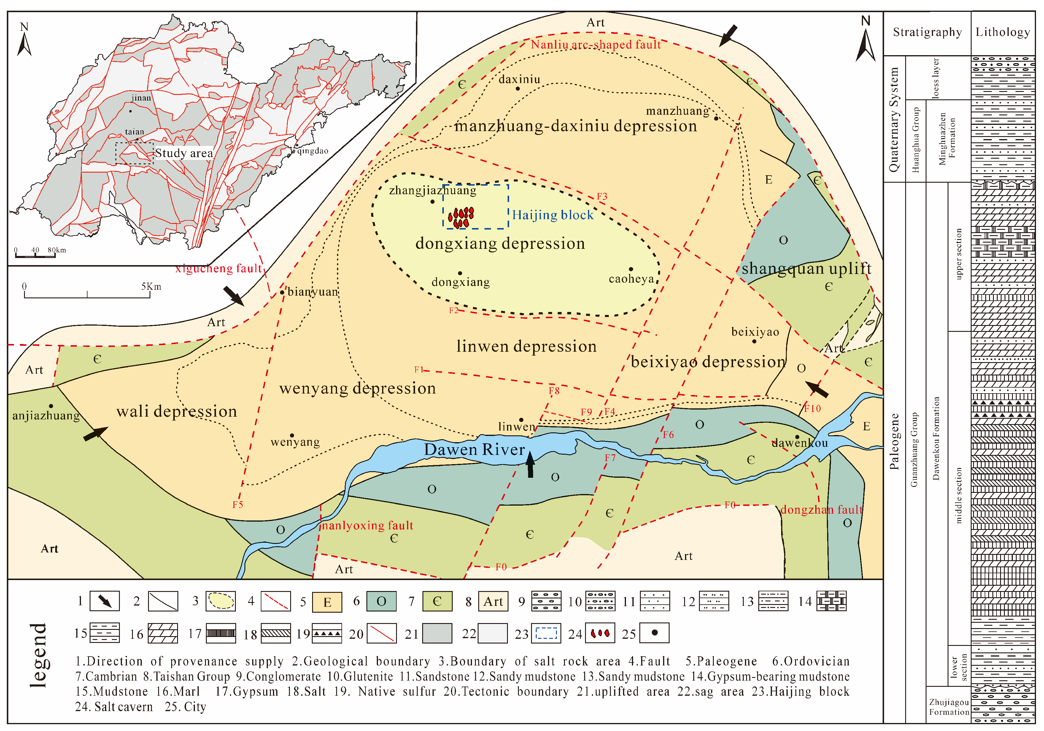
The Dawenkou Basin is located in the Luxi Uplift of the North China Plate. The basin basement is the crystalline basement of the Neoarchean Taishan Group, and the sedimentary cover is mainly composed of the Paleogene Guanzhuang Group Dawenkou Formation, which is the main host stratum of salt minerals such as rock salt and gypsum in the area [11,12]. The strata generally occur as gently dipping monoclines with an altitude of 305–345°∠4–11°, featuring stable structure, salt enrichment, and excellent sealing conditions. These advantages provide a stable geological structure background for the construction of salt cavern energy storage caverns [12,13] (Figure 1).

2.2. Characteristics of Salt Rock Reservoirs

2.2.1. Salt Layer Distribution

Controlled by the sedimentary cycle of the faulted basin, the salt rocks in the study area show continental sedimentary characteristics of multi-layer interbedding, alternating thin and thick layers, frequent interlayers, and rapid lateral facies change. This structure directly determines four core risks during salt cavern construction: wellbore instability, gas channeling, sealing failure, and an out-of-control cavity shape. Salt rocks are mainly hosted in the second member of the Paleogene Guanzhuang Group Dawenkou Formation (E2–3d). Controlled by the basin’s “north faulted and south onlapped” structural pattern and secondary sedimentary depressions, the salt layers show a spatial distribution pattern of enrichment in the sedimentary center and gradual thinning toward the edges [11,14]. The cumulative thickness of salt layers in the sedimentary center exceeds 160 m, and the burial depth gradually deepens from southeast to northwest. There are 32 ore-bearing layers with an ore-bearing rate higher than 40%. In the basin margin, the salt layer thickness is only 20–50 m, with 3–8 ore-bearing layers and an ore-bearing rate of 15–30% [15].
According to lithologic association and sedimentary cycle characteristics, the salt-bearing series in the Dawenkou Basin can be divided into a gypsum section, rock salt section, and gypsum–salt transition section from the bottom to the top. Gypsum is mainly hosted in the middle and upper members of the Dawenkou Formation, distributed in an elliptical shape with an area of about 160 km2. Rock salt is concentrated in the middle member of the Dawenkou Formation, distributed in a “mountain” shape with an area of about 50 km2. A huge thick gypsum cap layer develops at the upper part, presenting a lens shape gently dipping to the northwest. Single ore bodies occur in stable layered form with good continuity [9,11].

2.2.2. Interlayer Characteristics

The internal interlayers of salt layers are mainly anhydrite, followed by marl, gypsiferous marl, and a small amount of dolomite and mudstone, which are frequently interbedded with salt rocks [9,16,17]. The interlayer thickness ranges from 0.5 m to 25 m, with an average thickness of 5.8 m and permeability between 10−19 and 10−18 m2, which is significantly higher than that of a salt rock matrix (10−20–10−19 m2). The existence of interlayers easily induces wellbore instability, gas–liquid channeling, an out-of-control salt cavern shape, and sealing failure, making it the most important geological controlling factor for salt cavern construction in bedded salt rocks [17].
The sub-gypsum mudstone section is mainly composed of mudstone and claystone, which are micritic massive, brittle, and easy to soften when exposed to water, with an exposed thickness of 84.51–590.41 m. The supra-gypsum marl section is dominated by marl, intercalated with thin siltstone, fine sandstone, and sandy marl, with an exposed thickness of 70.31–391.78 m. The supra-salt and sub-salt gypsum sections are mainly anhydrite, intercalated with thin marl and dolomitic mudstone, providing good regional sealing cap layers for salt cavern energy storage caverns [12].

2.2.3. Hydrogeological Conditions

Groundwater in the study area can be divided into three types: loose rock pore water, bedrock fissure water, and carbonate karst water. Salt rock reservoirs are mainly affected by Paleogene fissure water. The groundwater in the salt-bearing section is high-salinity brine with a salinity of 150–200 g/L, and chemical components dominated by NaCl, CaCl2, and MgCl2. The water table depth is 10–50 m. High-salinity fluids impose stringent requirements on casing anti-corrosion, wellbore sealing, and cementing and bonding [12].
Pore water is mainly hosted in alluvial layers on both banks of the Dawen River and slope diluvial layers at the basin margin, with a water table depth of 3–12 m and hydrochemical type of HCO3·SO4-Ca [18]. Fissure water is widely distributed in the upper member of the Dawenkou Formation, with water abundance controlled by lithofacies and lithology. The water abundance in the northern margin of the basin is better than that in the central part, with a water table depth of 7.54–19.80 m and hydrochemical type of HCO3-Ca [12]. Karst water is mainly distributed at the basin margin with developed karst fissures, a water table depth of 30–100 m, and hydrochemical type dominated by HCO3-Ca [18].

2.3. Characteristics of Salt Cavern and Abandoned Well Distribution

2.3.1. Salt Cavern Distribution

Salt caverns in the study area are concentrated in the northwestern salt-bearing sedimentary center, all hosted in the salt-bearing strata of the middle member of the Dawenkou Formation. Their development and distribution are strictly controlled by lithofacies zones, stratum occurrence, structural conditions, and historical water-soluble mining activities. The cavity shape is mostly irregular elliptical- or dumbbell-shaped, with a single cavity volume of 20–80 × 104 m3.
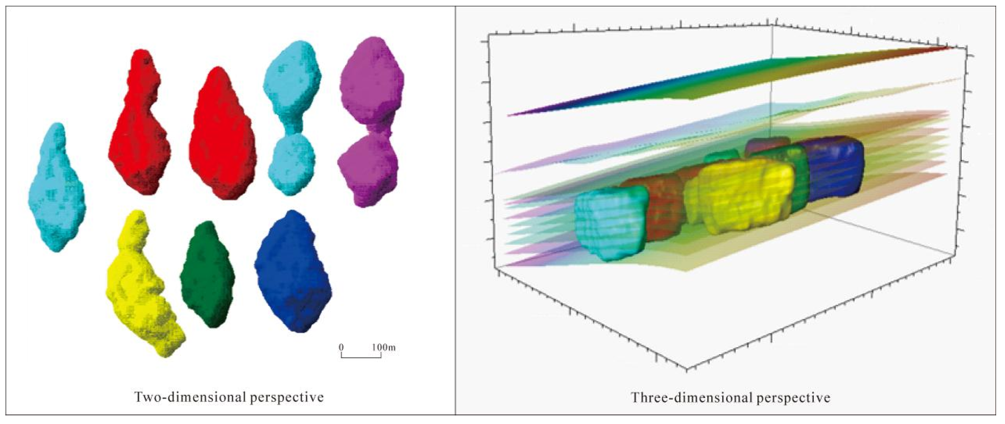
Planarly, salt caverns can be divided into three concentrated development areas, generally distributed in a nearly north–south direction, consistent with the well array layout direction. The PowerChina Feicheng 2 × 300 MW Salt Cavern CAES Power Plant plans to use 20 groups of salt caverns, mainly located in the Haijing Block. The salt cavern burial depth is 1200–1500 m, with a clear spatial distribution pattern (Figure 2). Vertically, salt caverns are controlled by the salt–gypsum interbedded structure, concentrated between No. 7 and No. 19 mineable salt layers. The maximum vertical height of the cavity is about 124 m, with the cavity bottom based on the bottom boundary of the No. 7 salt layer and the cavity top up to the No. 19–No. 21 salt layers, showing significant vertical stratification (Figure 2). The vertical fracture system developed in the salt-bearing strata further affects the cavity expansion morphology under water pressure, constituting an important influencing factor for salt cavern stability and sealing.

2.3.2. Abandoned Well Distribution

Abandoned old wells in the study area are concentrated in the northwestern core salt-bearing area, which includes all historical water-soluble brine production wells in the Haijing Salt Chemical Block, totaling 32 wells. Among them, 18 wells have potential safety hazards, such as casing damage, plugging failure, and poor sealing. The four key old wells involved in the project belong to two groups of well brine production systems, distributed in pairs, along the cavity, and in rows, highly matching the spatial pattern of salt caverns. Some old wells have been idle for a long time, with prominent risks of casing corrosion and perforation, and hidden dangers of brine leakage and gas channeling, making them major safety risk sources that must be handled in salt cavern energy storage cavern construction.
All old wells adopt a “one injection one production” paired layout, with two wells located at both ends of the salt cavern. The well spacing matches the transverse width of the cavity, and the wellbore trajectory extends along the long axis of the cavity, which is highly consistent with the cavity extension direction, providing a geological basis for accurate plugging of old wells and optimized layout of new wells.

3. Core Difficulties and Scientific Mechanisms of Bedded Salt Rock Energy Storage Cavern Construction

3.1. Mechanism of Wellbore Instability and Out-of-Control Trajectory Caused by Bedded Heterogeneity

Frequent interbedding of salt rock with gypsum rock, marl, and mudstone leads to significant differences in strength, creep characteristics, and dissolution resistance among different lithologies, forming obvious stress concentration near the wellbore [19,20]. Salt rock is prone to dissolution and diameter expansion as well as plastic flow, while interlayers are easy to collapse and spall, jointly causing an excessive borehole enlargement rate. The development of bedding and weak planes makes the well trajectory easily deviate along the bedding plane, and traditional directional control methods are difficult to meet high-precision requirements [21,22], directly reducing wellbore quality and cementing reliability. This mechanism provides a theoretical basis for the optimization of well trajectory precise control and wellbore stability technologies.

3.2. Mechanism of Gas–Liquid Channeling and Sealing Failure Induced by High-Permeability Interlayers

The heterogeneity of interlayer formations is the core control factor in assessing sealing reliability. The Dawenkou Basin exhibits thin alternating layers of salt, brine, and mud, with interlayer permeability ranging from 10−19 to 10−18 m2—1~2 orders of magnitude higher than that of the saltstone matrix—which readily forms dominant flow channels, leading to gas–liquid crossover and sealing failure [16,22]. This study introduces a salt–brine–mud interface creep incoordination coefficient in sealing evaluations to quantify interface delamination and damage evolution caused by mechanical differences between the interlayer and saltstone. A dual-stage milling multi-stage redundant sealing technique is employed to achieve full-section sealing, while ultra-fine cement slurry fills interlayer micro-fractures to block flow channels. The sealing evaluation system integrates multi-stage pressure testing, logging measurements, and long-term pressure monitoring [5,7]. Field validation demonstrates that the sealing body exhibits a 72 h compressive strength of 32–38 MPa with pressure attenuation ≤0.05 MPa, effectively mitigating the adverse effects of interlayer heterogeneity on sealing reliability.

3.3. Mechanism of Abandoned Well Sealing Failure Caused by Coupling of Alternating Load and Salt Rock Creep

Salt cavern energy storage operates under an alternating pressure of 10–20 MPa for a long time, and wellbores and plugging bodies bear periodic stress fluctuations [5]. The heterogeneous creep of bedded salt rock produces extrusion deformation on casings, aggravating interface damage. Alternating loads further lead to cement sheath cracking and cementing interface degradation, forming channeling channels. Conventional plugging only relies on cement plugs in the wellbore, which cannot resist the coupling effect of creep and fatigue, and cannot meet long-term sealing requirements. The creep–fatigue coupling effect determines the structure and material selection of the long-term sealing of the plugging body.
Long-term creep of salt rock is described by a power-law creep constitutive equation [10]:
ε ˙ = A σ n e Q R T
Fatigue damage in the plugging system under alternating loads was calculated using the Miner linear cumulative damage criterion [20]. This study employed FLAC3D (Version 7.0)/COMSOL (Version 6.4) to perform a fully coupled numerical simulation integrating fluid, solid mechanics, creep, and fatigue analysis, revealing the damage evolution and channel formation patterns across the triple interface of casing, cement ring, and formation. The findings provide a mechanical basis for designing multi-level redundant plugging structures.

3.4. Mechanism of Salt Precipitation Crystallization and Gas Injection–Brine Displacement Blockage Induced by Temperature–Pressure Fluctuations

During gas injection–brine displacement, decreasing pressure and temperatures can bring the brine to a supersaturated state, resulting in massive precipitation of salt crystals such as NaCl and CaSO4 [23]. Interlayers and irregular cavity shapes aggravate local eddy currents and low-pressure zones, accelerating crystallization blockage and gas lock formation, significantly reducing displacement efficiency and effective cavity utilization rates. The temperature–pressure coupled salt precipitation law provides scientific support for the optimization of anti-blocking technology in gas injection–brine displacement.

4. Key Construction Technologies

4.1. Technical System Composition

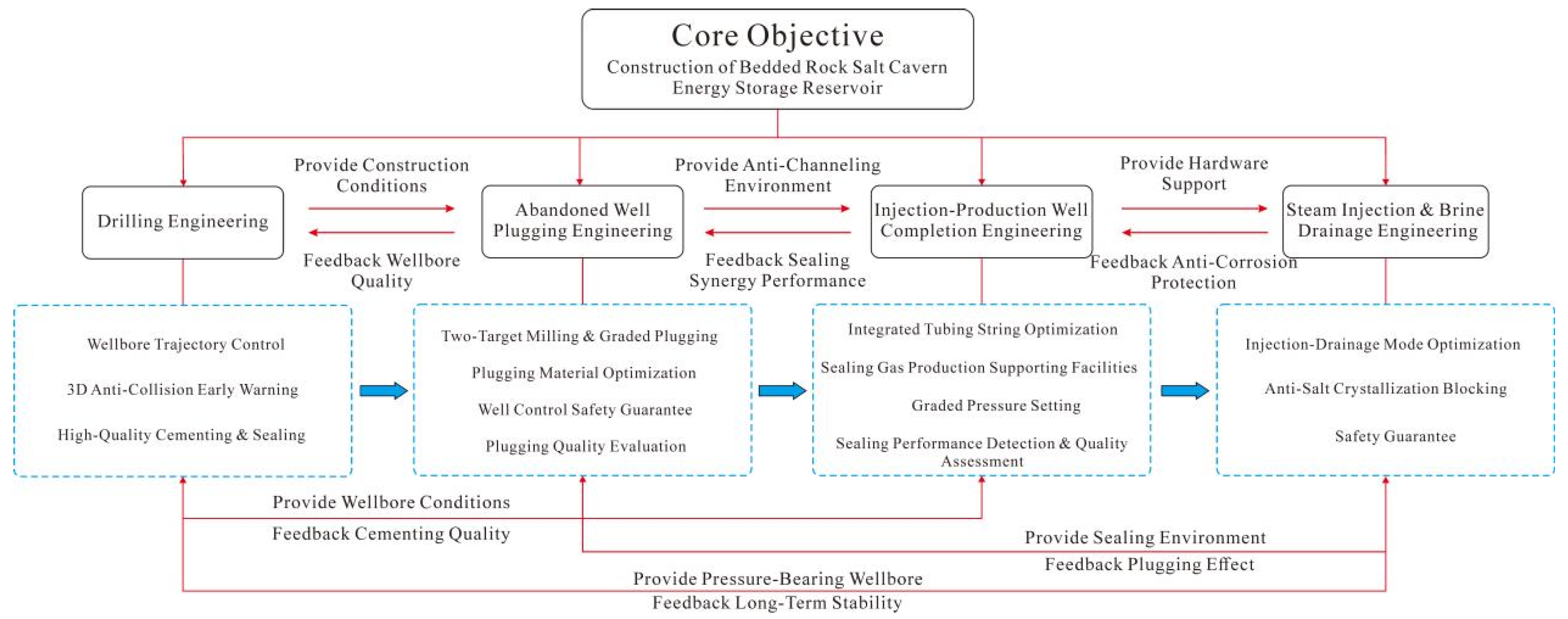
Aiming at the geological characteristics of continental bedded salt rock in the Dawenkou Basin, such as well-developed thin interbeds, strong heterogeneity, high interlayer permeability, and complex old cavity reconstruction conditions, combined with the engineering requirements of long-term high-pressure alternating operation, high wellbore sealing requirements, and long anti-corrosion service life of salt cavern CAES energy storage caverns, based on field tests, theoretical analysis, and process optimization, a full-process, integrated, and highly adaptable key technical system for bedded salt rock salt cavern energy storage cavern construction is constructed. With long-term safe operation, stable and reliable sealing, efficient and economical construction, and long-term wellbore anti-corrosion as core objectives, the system systematically covers four core technical modules, drilling engineering, abandoned well plugging, design of an injection and brine extraction device, and gas injection–brine displacement, forming a closed-loop technical chain from precise wellbore construction, permanent plugging of abandoned wells, a highly tight design of an injection and brine extraction device to efficient gas injection–brine displacement, realizing standardized, refined, and intelligent control of the whole construction process of bedded salt rock salt cavern energy storage caverns (Figure 3).
The four technical modules are characterized by sequential progression, two-way coupling, and closed-loop collaboration: drilling engineering provides a wellbore carrier for the whole system, abandoned well plugging constructs a global sealing barrier, design of an injection and brine extraction device forms a long-term service system, and gas injection–brine displacement realizes cavity commissioning and operation. The previous process provides a construction foundation for the subsequent process, and the subsequent process reversely verifies the quality of the previous process through inspection data, jointly forming a full life cycle technical closed loop of energy storage caverns.

4.2. Key Drilling Engineering Technologies

The salt rock in the Dawenkou Basin is characterized by small single-layer thickness, dense interlayers, strong heterogeneity, easy dissolution and diameter expansion, and weak-cap-layer pressure-bearing capacity. Salt cavern energy storage drilling must simultaneously meet four core requirements: precise trajectory anti-collision, wellbore stability and diameter control, long-term cementing sealing, and high-pressure safe pressure bearing. Traditional drilling technologies are difficult to adapt to complex geological conditions [24,25]. Based on the geological conditions and engineering requirements of the study area, multi-technology collaborative optimization is adopted to ensure wellbore integrity and long-term service stability, laying a foundation for salt cavern energy storage cavern construction.

4.2.1. Optimized Design Technology of Well Structure

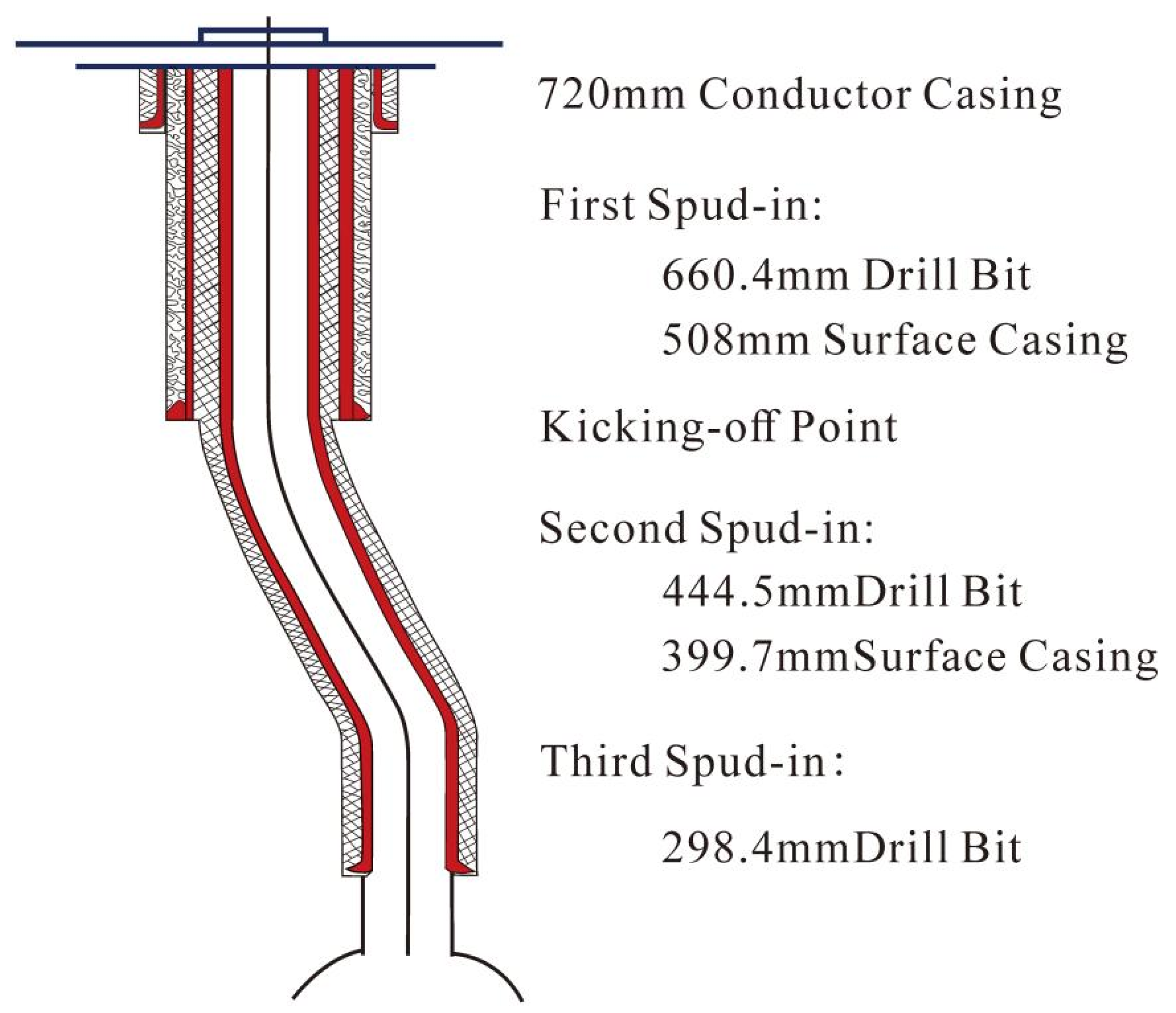
The well structure design parameters were determined based on geological conditions such as the shallow, soft strata of the Dawenkou Basin, salt rock creep-induced diameter reduction, and high sealing requirements of overlying formations, in compliance with drilling industry standards for salt cavern gas storage reservoirs and API specifications (Table 1). These parameters also meet engineering demands for high-pressure gas storage, long-term sealing, collision resistance, and corrosion protection [19,21]. Key control parameters include: a maximum well deviation angle ≤ 1.0°; a total angular variation rate ≤ 1.0°/30 m; horizontal displacement ≤ 2 m; a first-opening diameter expansion rate ≤ 12% and second and third openings ≤ 10%; casing materials of P110 and 110HC steel grades, which were selected according to requirements for anti-puff failure, corrosion resistance, and airtight sealing; and a cement slurry density of 1.85–1.90 g/cm3 with 24 h compressive strength ≥7.0 MPa (Figure 4, Table 2). Field verification using Measurement While Drilling (MWD) real-time inclination measurement, three-level collision prevention alerts, and Cement Bond Log (CBL)/Variable Density Log (VDL) showed a wellbore trajectory control error ≤0.4 m, a diameter expansion rate ≤ 7.8%, high-quality cementing rate of 92%, and casing pressure test results demonstrating a pressure drop ≤ 0.5 MPa at 10 MPa/30 min—all meeting and exceeding design parameters with excellent model-field consistency [7,26].
A high-precision MWD while-drilling inclinometer system was used for real-time monitoring. Combined with adjacent well trajectories and 3D salt cavern models, a three-level anti-collision early warning mechanism was established: an early warning distance ≥ 50 m, a warning distance of 30–50 m, an emergency shutdown distance ≤ 30 m, ensuring the minimum safe distance between new wells and old wells ≥ 30 m, and avoiding well collision risks throughout the design and construction process.

4.2.2. High-Efficiency Cementing and Long-Term Sealing Technology

Salt cavern gas storage facilities impose extremely high requirements on cementing bonding quality and long-term sealing performance. Casing string and cement slurry system optimization was carried out based on geological conditions of different well sections (Table 3). The casings adopt a graded adaptive design: a conductor pipe of Φ720 mm (Q235B), first spudding of Φ508 mm (J55), upper part of second spudding of Φ339.7 mm (P110), and lower part of second spudding that adopts 110HC collapse-resistant casing, equipped with special threads such as air-tight joints to improve sealing reliability.
Cementing adopts a salt-resistant and corrosion-resistant high-performance cement slurry system (Table 4), a Grade G high-sulfur-resistant oil well cement (+2.0–3.0%) early-strength agent (+0.2–0.5%) dispersant, a density of 1.85–1.90 g/cm3, 24 h compressive strength ≥7.0 MPa, a thickening time ≥ construction time (+45 min), initial consistency ≤25 Bearden Consistency Units (Bc), adapting to low-temperature and high-salinity environments of salt layers and ensuring interface bonding strength and long-term sealing performance.
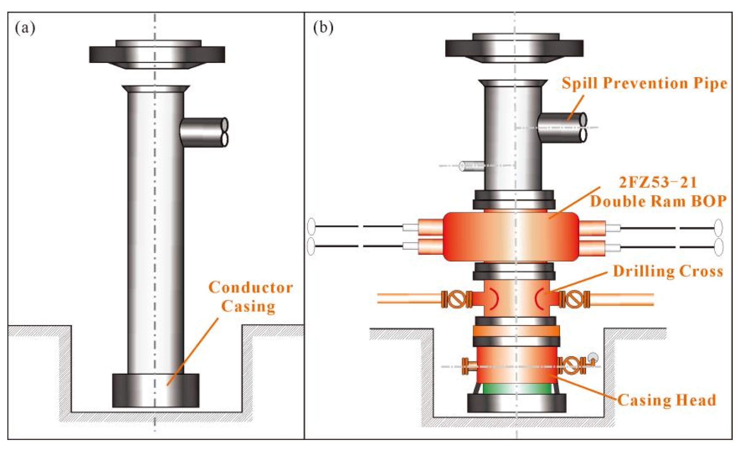
The cementing technology adopts optimization measures such as the interpolation method and double-plug displacement. Cement slurry was returned to the ground. After 72 h of waiting for cement setting, CBL/VDL was used to evaluate cementing quality, and casing pressure testing was carried out: both first spudding of Φ508 mm and second spudding of Φ339.7 mm were tested at 10 MPa, stabilized for 30 min, and qualified if there was a pressure drop ≤0.5 MPa, ensuring cementing sealing met long-term high-pressure gas storage requirements (Table 5). A complete well control system was equipped, including a ZJ40 drilling rig, a 2FZ53-21 double ram blowout preventer, and throttle/kill manifold, comprehensively preventing risks such as lost circulation, sticking, and harmful gas channeling and overflow (Figure 5).

4.3. Key Abandoned Well Plugging Technologies

Salt cavern energy storage caverns operate under high-pressure alternating load conditions for a long time, and abandoned old wells are the main risk sources of sealing failure and gas channeling. Different from conventional oil and gas well plugging that only focuses on cement plug sealing in the wellbore, salt cavern abandoned well plugging must simultaneously overcome multiple challenges, such as casing–cement sheath-formation interface degradation, salt rock creep extrusion, alternating stress fatigue, and developed annular channeling channels. Conventional plugging processes cannot meet long-term sealing requirements [27,28,29].

4.3.1. Technical Difficulties and Design Principles

The core difficulties of bedded salt rock abandoned well plugging are as follows [30]:
(1)
The sealing system is prone to fatigue failure under alternating loads;
(2)
Cementing interface bonding degradation forms channeling channels;
(3)
Salt rock creep extrusion causes casing deformation and damage;
(4)
There is poor compatibility between plugging materials and salt rock/mudstone.
Three design principles were established accordingly: full-section plugging to completely eliminate the risk of casing–cement sheath-formation interface leakage through casing section milling and formation reaming; multi-stage redundant sealing to construct five independent sealing barriers and verify section by section through pressure testing, ensuring that a single barrier failure does not affect the overall sealing performance; and formation adaptability optimization to adopt saturated salt water drilling fluid in salt layer sections to inhibit salt rock dissolution, and ultra-fine cement slurry in cap layer sections to achieve precise plugging of formation micro-fractures.

4.3.2. Core Technology of Dual-Section Milling Graded Plugging

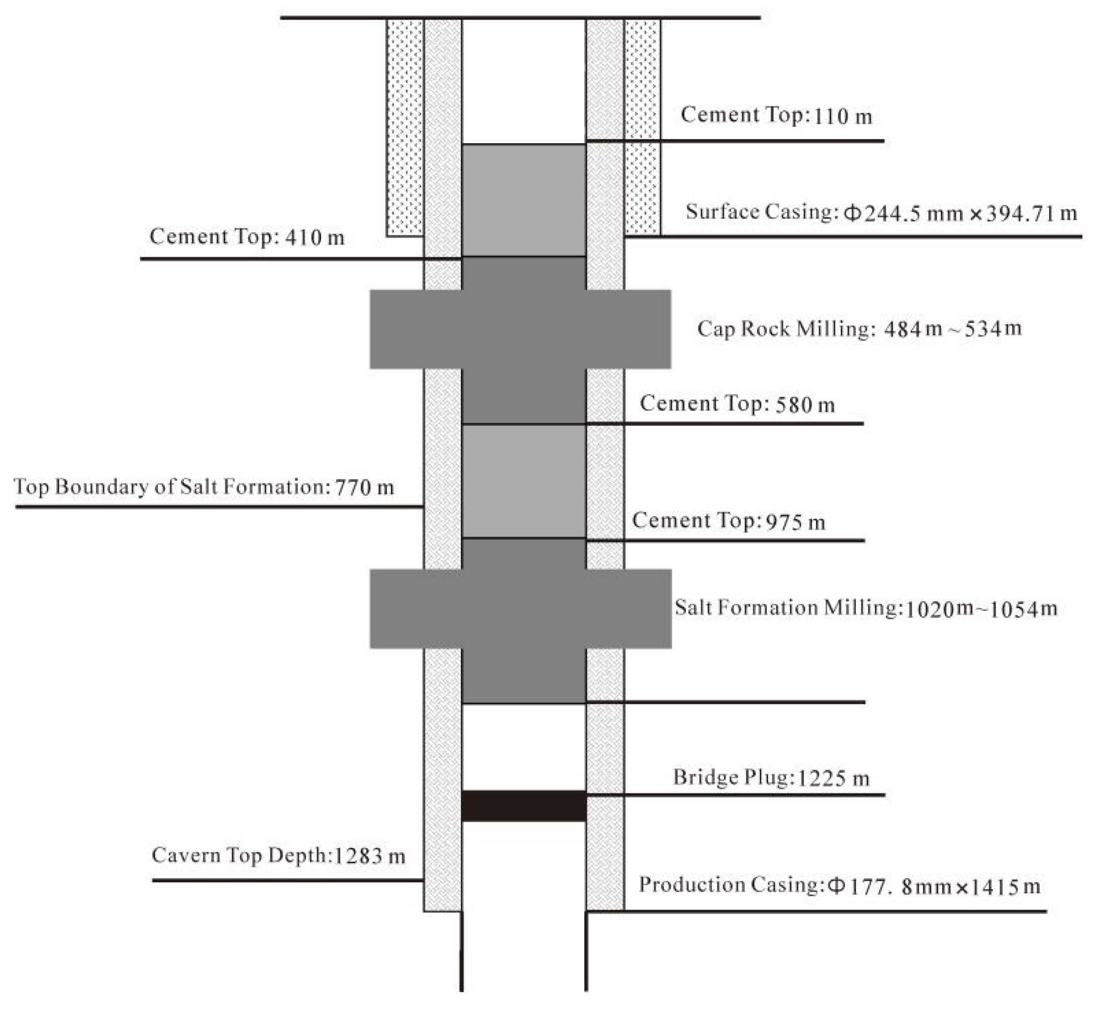
Aiming at scientific problems such as casing–cement sheath-formation interface channeling, creep extrusion, and alternating load fatigue failure faced by bedded salt rock abandoned well sealing, the design concept of multi-stage barriers, full-section plugging, and redundant sealing is proposed. An integrated plugging technology of dual-section milling–reaming–grouting was developed to cut off fluid channeling channels in the mechanism. The cap layer section milling length was 50 m, and the salt layer section milling length was 30 m, realizing full-section isolation of cap layer and salt layer dual-risk areas (Figure 6). Wellbore pretreatment included controlled pressure relief, bottom-hole debris detection, and casing scraping to ensure a clean wellbore free of sand settlement and scale layers. A drillable bridge plug was run at 1225 m, and a 120 m thick bottom plug cement was injected. After 48 h of waiting for setting, pressure testing was carried out to form the first sealing barrier.
In the salt layer section, TDX-178 milling tools were used to remove 34 m casings, KYG reamers were used to ream to the original formation, and saturated salt water ultra-fine cement slurry was injected and returned to 50 m above the top boundary of the milling section. After 72 h of waiting for setting, high-pressure testing at 21 MPa was carried out. An isolation plugging section was set in the middle to block longitudinal channeling. The cap layer section adopted the same milling–reaming process, injecting special ultra-fine cement slurry to penetrate into mudstone micro-fractures and realize top locking sealing.
Numerical analysis procedure [7,31]: ① A three-dimensional model of the casing–cement ring-stratum was established; ② alternating internal pressures of 10–20 MPa and salt rock creep-induced ground stresses were applied; ③ dual-interface damage, stress concentration, and channel evolution were calculated; ④ the dual-stage milling lengths, multi-stage plugging structure, and material parameters were optimized; and ⑤ the long-term reliability of the sealing was confirmed through on-site pressure testing at 21 MPa.

4.3.3. Formation Adaptability Optimization of Plugging Materials

The selection of sealing materials involved a comprehensive comparison of resin-based cement and expansive cement systems. Resin-based cement exhibits poor interfacial bonding performance and is prone to brittle cracking in high-mineralization brine environments, failing to meet long-term sealing requirements; expansive cement tends to over expand in salt formations, causing casing deformation, and lacks sufficient salt resistance and corrosion resistance [27,30]. Preliminary field tests demonstrated that both materials achieved less than 60% sealing success rates under thin interlayer conditions with high salinity and salt rock creep composite scenarios, falling short of permanent sealing requirements. Consequently, a tiered material adaptation strategy was implemented based on formation characteristics: the salt layer section employs saturated brine ultrafine cement slurry to inhibit salt dissolution and fill micro-fractures, achieving a 72 h compressive strength of 32~38 MPa; the cap layer section uses high-strength, low-permeability ultrafine cement slurry suitable for mudstone fracture sealing and resistant to alternating fatigue damage; and the bottom plug and isolation section employ Grade G oil well cement, characterized by high early strength and stable interfacial bonding [5,28]. Field applications confirmed a 100% sealing success rate and successful high-pressure testing at 21 MPa, meeting the long-term sealing requirements for aged, layered salt rock wells.

4.3.4. Well Control and Safety Support

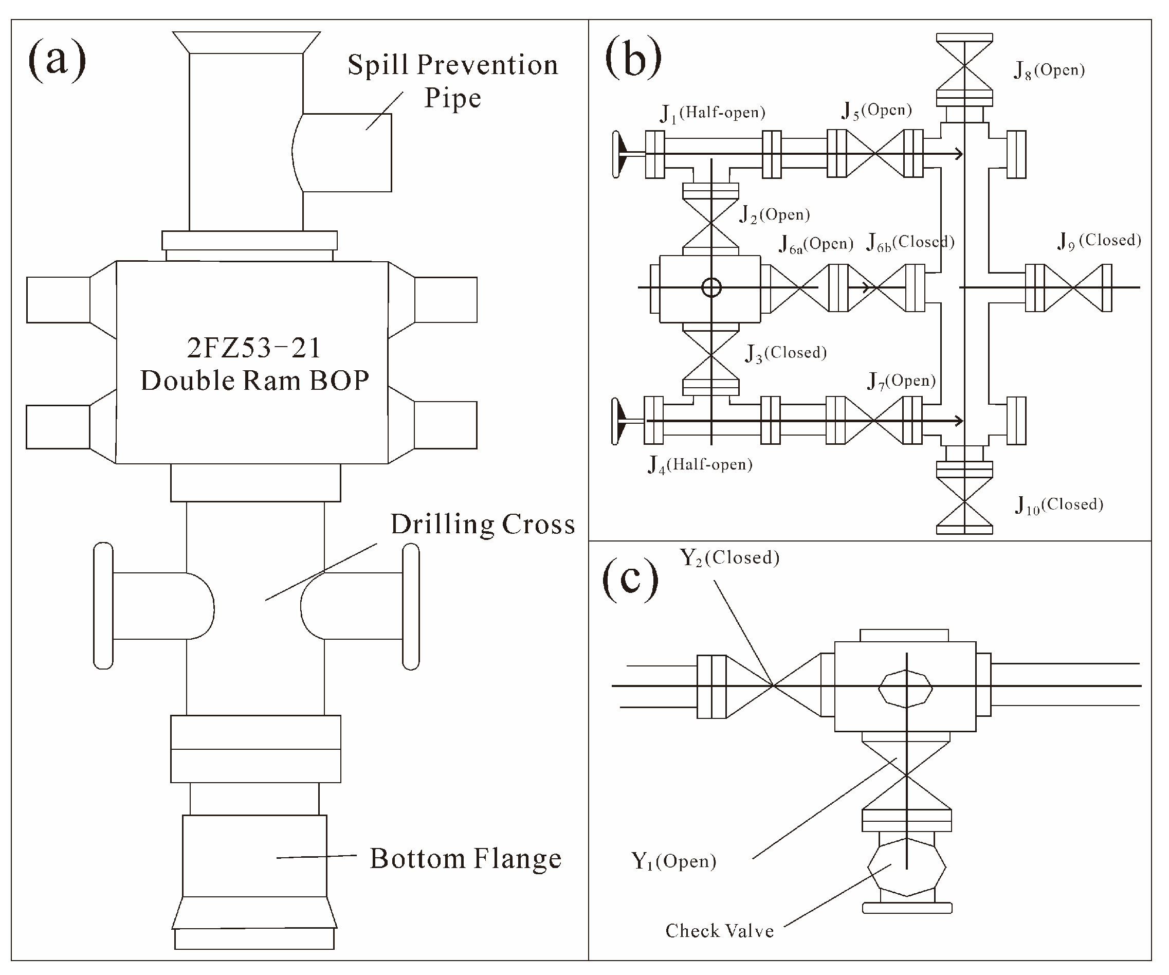
A 2FZ18-35 double ram blowout preventer and 35 MPa class throttle/kill manifold were selected, with installation verticality deviation ≤10 mm. Pressure testing was carried out to 21 MPa, stabilized for ≥10 min, and qualified if there was a pressure drop ≤0.7 MPa, constructing a complete well control safety system to prevent high-pressure gas channeling and overflow risks (Figure 7).
Equipment selection criteria: ① The alternating operating pressure in salt caverns exhibits fluctuations; a safety margin of twice the maximum working pressure (15.61 MPa) is reserved [7,32]; ② compliance with GB/T 22513-2023 and the mandatory standard requiring a rated pressure of no less than 35 MPa for underground gas storage reservoir well control equipment is met [33,34]; ③ adaptability to high leakage risks and numerous aging wells in this region is achieved, meeting extreme operational well control requirements [7,31].

4.3.5. Full-Process Evaluation System for Plugging Quality

A full-process evaluation system of multi-stage barrier sectional pressure testing + logging detection + long-term monitoring was established: each stage of plugging was tested at 21 MPa of high pressure, stabilized for 30 min, and qualified if there was a pressure drop ≤ 0.5 MPa; electromagnetic flaw detection and CBL/VDL logging were combined to evaluate casing integrity and cement sheath bonding quality; a long-term pressure monitoring system was implemented after commissioning, realizing full-life cycle management and control of plugging effects and ensuring 100% permanent sealing.

4.4. Key Design Technologies of an Injection and Brine Extraction Device

The bedded salt rock salt cavern energy storage caverns in the Dawenkou Basin face problems such as complex gas injection–brine displacement conditions, high long-term wellbore sealing requirements, strong brine corrosion, and poor adaptability of old cavity reconstruction. Combined with wellbore integrity and long-term service requirements, Key Design Technologies of an injection and brine extraction device technologies with high tightness, strong corrosion resistance, full sealing, and standardization are developed, covering four core links: string optimization, wellhead matching, construction technology, and sealing detection, forming a completion technical system suitable for continental bedded salt rock, providing core support for long-term high-pressure injection and brine extraction operation of salt cavern CAES caverns [24].

4.4.1. Optimal Design of Injection–Production

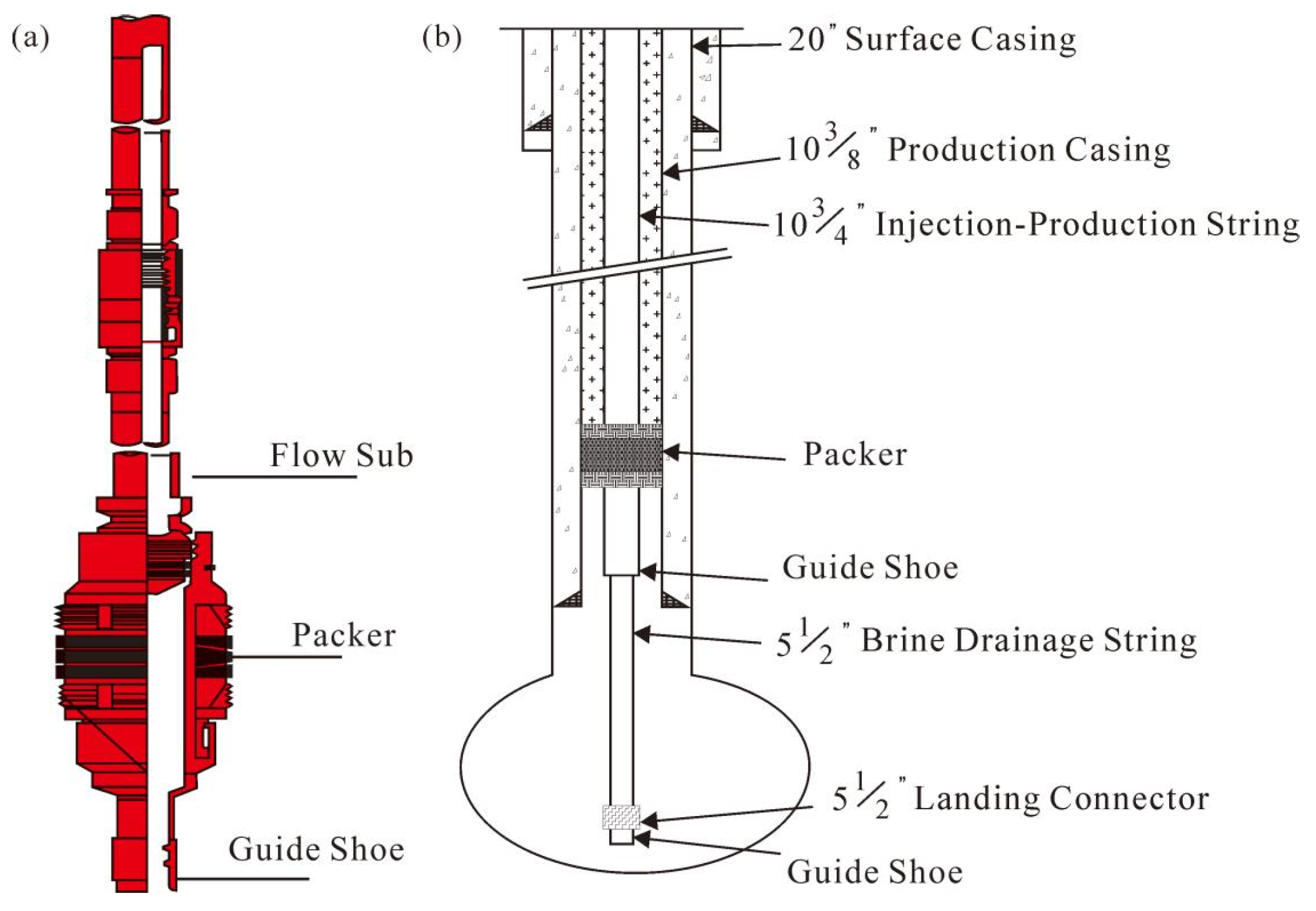
Aiming at long-term safe operation, large-flow peak regulation, and efficient gas injection–brine displacement, following the design principles of layered pressure bearing, air-tight sealing, anti-corrosion adaptation, and tool generalization, refined management and control design of strings was realized based on industry and national standards, combined with cavity measurement reports and formation pressure parameters (Figure 8).
Injection–production strings adopted P110-grade laser cladding anti-corrosion air-tight pipes with an outer diameter of 273.05 mm and wall thickness of 11.43 mm, equipped with ZT-XC(I) air-tight special threads. Inner-wall/inner- and outer-wall cladding treatment significantly improved brine corrosion resistance. The string assembly was a guide shoe + injection–production pipe + hydraulically set permanent packer. The packer setting position strictly avoided casing couplings to realize permanent annular sealing. Brine displacement strings adopted N80-grade high air-tight tubing, assembled with guide shoes, short tubing, and landing nipples, with a running depth of 1.0–1.5 m from the cavity bottom. The length was accurately adjusted according to sonar cavity measurement and field bottom detection data to ensure unobstructed displacement channels without dead corners (Table 6).
Helium sealing testing was carried out on each string before running into the well, with a testing pressure not less than 1.1 times the upper operating limit pressure, eliminating thread leakage risks from the source and meeting the long-term service requirements.

4.4.2. Standard Matching of Christmas Tree and Wellhead Equipment

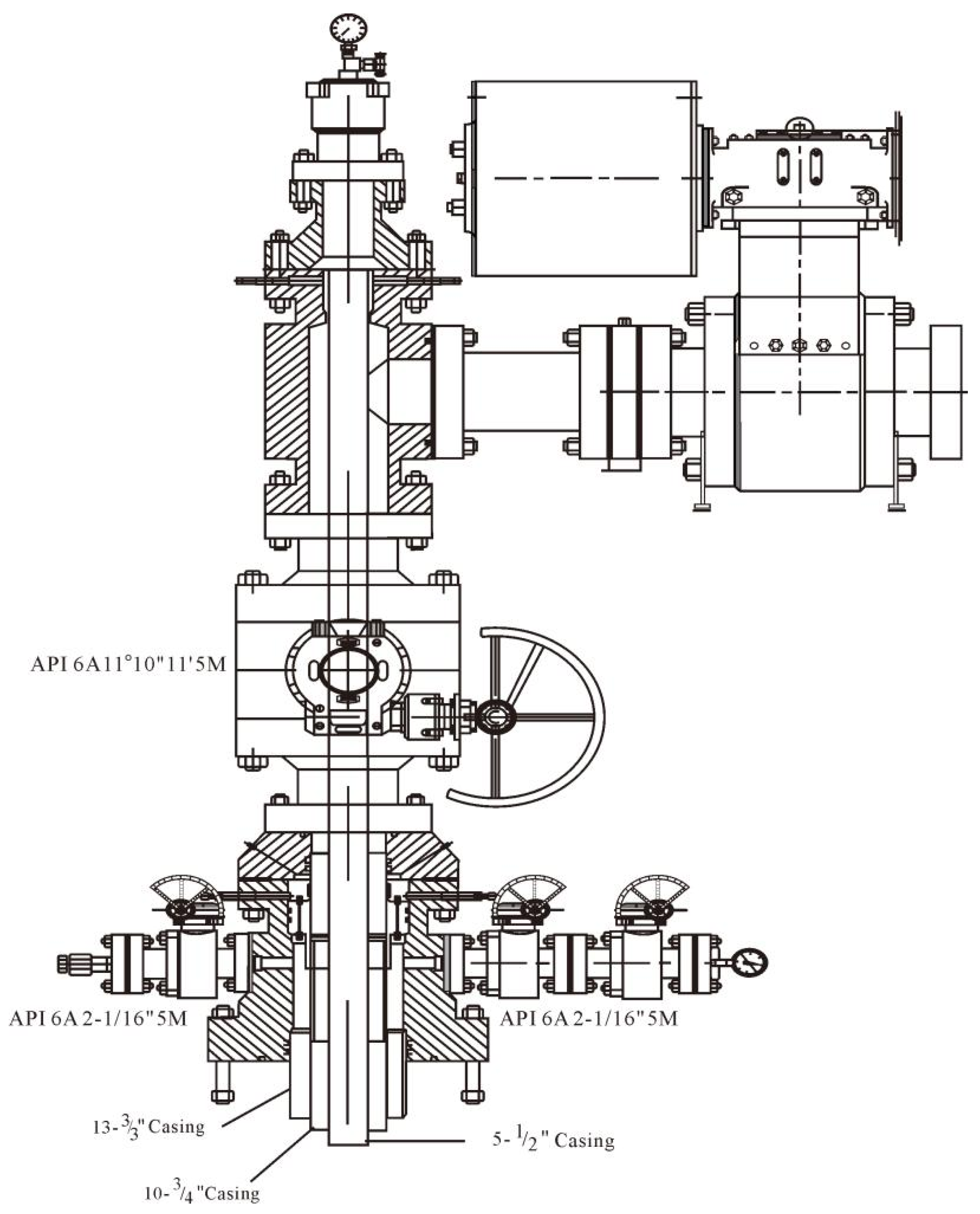
The Christmas tree adopted a double-main-valve single-wing high-pressure structure, strictly implementing API6A-21TH standards, with a pressure grade ≥35 MPa, Product Specification Level (PSL)-3G specification grade, Performance Requirement (PR)2 performance grade, and Exposure Environment (EE) material grade, adapting to salt cavern high-pressure alternating operating conditions. All natural gas contact parts adopted full-metal sealing, flanges and steel rings adopted anti-corrosion stainless-steel materials, and valve seats adopted full-metal hard sealing, compatible with full-condition operations such as brine displacement string extraction, gas injection, pressure testing, and detection. The wellhead sealing performance was not affected after tubing hanger disassembly and assembly (Figure 9).
The wellhead system adopted a graded pressure-bearing integrated design. Injection and brine extraction device wellheads, brine displacement tubing hangers, and Christmas trees were accurately matched, with a casing head installation verticality ≤0.5°, forming a standardized completion wellhead structure and realizing seamless connection between wellbore and ground systems, comprehensively improving wellhead sealing and operation and maintenance safety.

4.4.3. Graded Pressure Testing, Setting, and Sealing Verification Technology for Injection and Brine Extraction Device Completion

Relying on a ZJ40 drilling rig, non-marking hydraulic torque casing tongs, a nitrogen pump truck, and a high-precision air-tight testing device, an integrated standardized completion construction system of wellbore pretreatment–string running–packer setting and sealing verification–wellhead installation–full-process quality control was constructed, realizing long-term wellbore sealing and integrity management and control.
Before construction, wiper trip, casing scraping, and reverse freshwater displacement were carried out to remove wellbore scale and sediment, inhibiting salt rock recrystallization blockage. The running speed was strictly controlled during string running, and packer protection was done to avoid mis-setting. The make-up torque was accurately controlled to ensure thread connection sealing reliability. A graded pressure testing process was adopted to complete packer setting and sealing verification, realizing effective isolation between salt caverns and upper wellbores. Meanwhile, special annular protective fluid (corrosion rate: ≤0.02 mm/a) was injected through reverse circulation to construct a long-term wellbore anti-corrosion system. The wellbore fluid system was optimized and combined with bedded salt rock geological characteristics, forming a multi-medium collaborative protection mechanism of “freshwater inhibiting salt crystallization, saturated brine stabilizing cavity pressure, and annular protective fluid anti-corrosion and water isolation”.
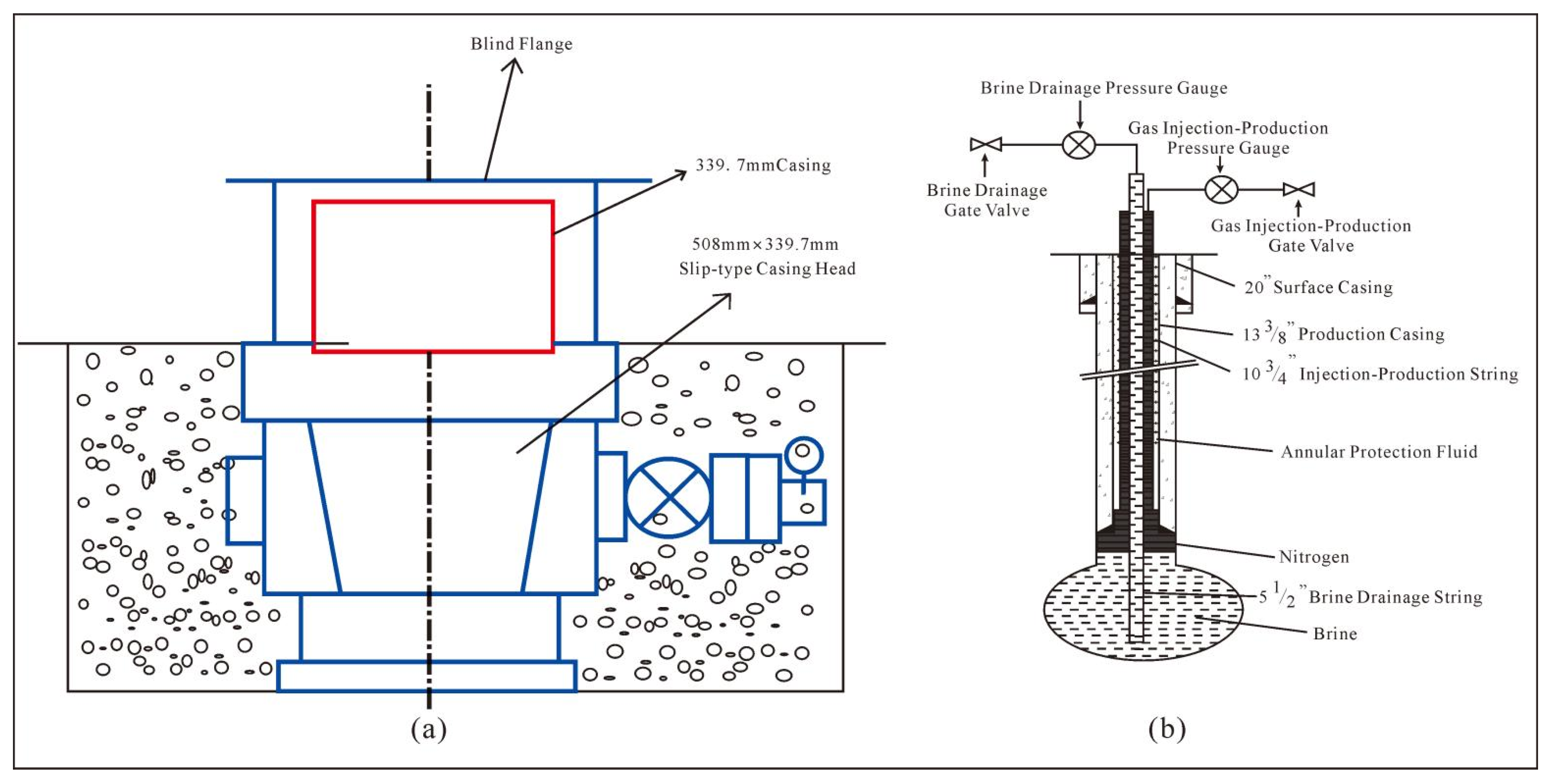
The full-process quality control standard was implemented in the completion stage: casing head installation verticality was controlled within ≤0.5°, high-pressure gates adopted anti-corrosion protection measures, and wellhead installation size and wellsite layout met long-term operation and maintenance requirements, forming a standardized complete wellhead structure (Figure 10), ensuring reliable connection between wellbore and ground gas injection–brine displacement systems, and providing basic support for subsequent gas injection–brine displacement operations and long-term safe operation of energy storage caverns.

4.4.4. Integrated Wellbore-Cavity Sealing Detection and Completion Quality Evaluation

A three-level quantitative sealing evaluation system was established. Nitrogen was used as the test medium for 24 h continuous pressure stabilization testing, realizing quantitative evaluation of the full system sealing of the injection and brine extraction device and salt cavern cavities (Figure 10).
Sealing testing adopted graded judgment standards. Cavity sealing was qualified if the leakage rate continuously attenuated and tended to be stable, and gas–water interface depth change was less than 1.0 m. Gas injection–brine displacement required no pressure rise and gas channeling in the annulus during testing. Brine displacement string sealing was qualified if no sudden pressure rises and gas leakage occurred during pressure testing. High-precision pressure gauges, gas flowmeters, and gas–water interface detectors were equipped on-site for testing, thus constructing a full life cycle management and control standard for completion quality.

4.5. Key Gas Injection–Brine Displacement Technologies

Aiming at technical bottlenecks such as irregular salt cavity shapes, easy gas channeling short circuits due to developed interlayers, easy crystallization blockage of saturated brine, and low displacement efficiency in the Dawenkou Basin, an old cavity-adaptive gas injection–brine displacement technical system was developed to realize efficient brine displacement, maximum utilization of salt cavity space, and safe and controllable operation.

4.5.1. Optimization of Old Cavity-Adaptive Gas Injection–Brine Displacement Modes

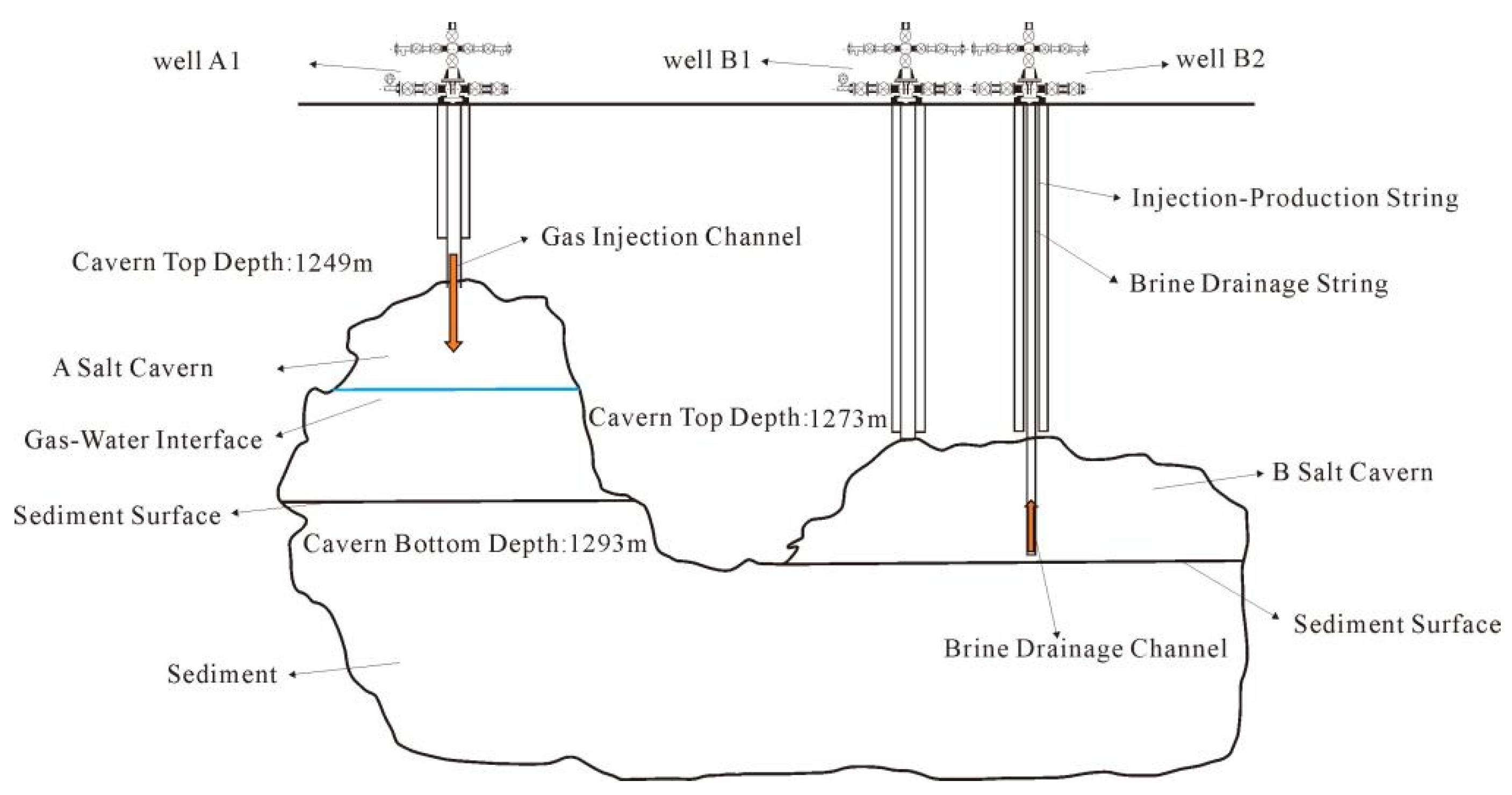
A reconstruction scheme of “plugging old wells + new drilling injection–production wells” was adopted [35]. The new drilled wells A1 and B1 were used as gas injection wells and B2 as a brine displacement well. Based on the actual geological conditions of the construction site and equipment capabilities, combined with relevant engineering construction experience, an innovative dual-mode six-stage gas injection–brine displacement process is proposed, eliminating brine retention dead zones and avoiding gas short circuits through gas injection well switching and displacement dynamic regulation (Table 7).
Mode 1 (one injection, one production): A1 gas injection → B2 brine displacement, which was divided into three stages of displacement control: 40–50 m3/h in the early stage for pressure building, 100–120 m3/h in the middle stage for efficient displacement, and 40–50 m3/h in the late stage for fine finishing.
Mode 2 (two injections, one production): A switch to B1 gas injection → B2 brine displacement was carried out, and the three-stage displacement control was repeated. Finally, double gas injection wells were pressurized synchronously to the upper operating limit pressure for static stabilization operation. A high-strength injection and brine extraction device, emergency shut-off valves, high-precision metering, and safety control systems were equipped to realize safe and controllable whole-process operation (Figure 11).

4.5.2. Key Anti-Salt Crystallization Blockage Technologies

To address the clogging issue caused by NaCl and CaSO4 crystallization due to brine pressure reduction and temperature drops [23], a three-in-one anti-clogging technical system was developed based on field engineering validation.
(1)
Regular backwashing for 1–2 h daily to inhibit crystal adhesion;
(2)
Brine displacement flow controlled to 40–150 m3/h to avoid excessive local pressure drops;
(3)
Gas injection pressure fluctuations ≤0.3 MPa/h, ground pipeline insulation, and brine temperature drops controlled to ≤5 °C, reducing crystallization precipitation risks from the source.
A flow-pressure linkage early-warning mechanism was established, and an enhanced unblocking procedure was started in case of abnormality to ensure continuous and stable system operation.

4.5.3. Full-Process Safety Support and Fault Handling Technologies

A multi-parameter linkage safety management and control system was established: real-time monitoring of gas components, with immediate shutdown when toxic and harmful gases exceeded standards; numerical simulations of gas injection and brine discharge that indicate that the salt cavern gas injection pressure upper limit was strictly controlled to ≤15.61 MPa, with automatic emergency shut-off in case of overpressure; and a ground system qualified in pressure testing, with instrument accuracy errors ≤0.5%. Standardized handling processes such as backwashing unblocking, mechanical unblocking, and string detection and replacement were formulated to comprehensively prevent safety risks, such as blockage, overpressure, leakage, and gas channeling [31,36].

5. Discussion

5.1. Comparison of Advantages Between This Technical System and Existing Domestic and Foreign Technologies

Aiming at geological shortcomings of continental thin interbed salt rock such as strong heterogeneity, easy channeling of interlayers, and poor wellbore stability, the full-process construction technical system constructed in this paper achieved performance breakthroughs in all links of drilling, plugging, completion, and gas injection–brine displacement. Its technical advantages can be verified through engineering indicators and scientific mechanisms.
In the field of drilling engineering, traditional processes do not consider the mechanical anisotropy of salt–gypsum–mud interbeds, with prominent problems of wellbore dissolution expansion and trajectory deviation. The conventional borehole enlargement rate in the industry is >15%, and trajectory control errors are >1.0 m. This paper optimizes the four-stage well structure and adopts MWD high-precision trajectory collaborative control. It effectively inhibits interlayer disintegration and salt rock plastic enlargement. Field engineering application verification shows that the drilling trajectory control error is less than or equal to 0.4 m. The wellbore enlargement rate is less than or equal to 7.8%. The high-quality cementing rate is 92%. The core indicators are at the same advanced level as domestic mature salt cavern projects in Jintan and Huai’an [1,7,16].
In the field of long-term abandoned well sealing, conventional single-stage cement plugging cannot resist the coupling damage of salt rock creep and alternating air pressure, and casing–cement sheath interfaces are prone to form channeling channels. Field engineering application verification shows that the dual-section milling multi-stage redundant plugging technology developed in this paper eliminates casing–cement sheath interface leakage risks through full-section isolation, achieving a 100% plugging success rate on site, a 72 h compressive strength of the plugging body of 32–38 MPa. The casing corrosion rate is less than or equal to 0.02 mm/a, meeting the sealing requirements of long-term service of energy storage caverns [23,24,29,36].
In the field of gas injection–brine displacement, traditional single-mode injection–displacement processes easily cause cavity gas channeling short circuits and salt crystal precipitation blockage, with an average cavity effective utilization rate of less than 85% in the industry. Field engineering application verification shows that the brine drainage cycle of a single cavity is shortened to 9.7 days. The brine drainage efficiency and salt cavern effective utilization rate are greatly improved, with technical performance being significantly better than domestic bedded salt rock old cavity reconstruction projects [3,37].
This technical system overcomes the constraints of thin interbedded geology, and its overall performance is comparable to the best international practices for continental bedded salt rock salt cavern energy storage engineering.

5.2. Mechanistic Explanation of Construction Effect Differences Between Bedded Salt Rock and Salt Domes

There are significant differences in construction effects between continental bedded salt rock and marine salt domes, essentially due to differences in sedimentary structure, mechanical properties, and permeability laws [1,17]. Marine salt domes are characterized by greater thickness, pure texture, few interlayers, low permeability, and uniform creep, and foreign mature reservoir construction technologies can be directly applied [25]. More than 90% of salt rocks in China are continental bedded salt rocks, showing characteristics of salt–gypsum–mud thin interbeds, strong heterogeneity, interlayer permeability that is 1–2 orders of magnitude higher, and rapid lateral facies change, easily inducing engineering problems such as wellbore instability, gas–liquid channeling, sealing failure, and gas injection short circuits [19,22].
The technical system in this paper carries out targeted innovation for the above mechanism defects: solving wellbore expansion and deviation problems through high-precision trajectory control; cutting off high-permeability interlayer channeling channels through multi-stage redundant plugging; solving strong brine corrosion problems through laser cladding completion; and eliminating gas channeling and crystallization blockage through dual-mode gas injection–brine displacement, thus realizing safe and efficient reservoir construction under complex bedded salt rock conditions.

5.3. Limitations and Future Research Directions

This study was carried out based on the geological conditions of the Dawenkou Basin with a burial depth of 1200–1500 m, a stable structure, and undeveloped faults, and the results have strong regional applicability. For areas with a burial depth >1800 m, complex tectonic stress, or developed faults, relevant process parameters still need further optimization and verification.
When comparing the permeability of rock salt and interlayer formations, the distinction between intrinsic permeability and extrinsic permeability was overlooked, with both types being uniformly categorized as intrinsic permeability—a practice that imposes inherent limitations on related engineering designs.
When investigating rock salt crystallization blockage issues, anti-blockage solutions may not be applicable to colder formations or higher drawdown ratios. Moreover, these solutions do not address the problem based on thermodynamic principles, nor do they consider measures such as heating or thermal insulation to resolve the issue.
Future research can be deepened in three aspects:
(1)
Distinguish the permeability types of rock salt and interlayer formations, and develop a more refined well sealing technology. Design comparative experiments to evaluate the effectiveness of heating in resolving rock salt crystallization blockage issues.
(2)
Carry out long-term creep tests of ultra-deep salt layers under high temperatures and high pressures, reveal the collaborative damage mechanism of wellbore plugging body formation under alternating loads, establish a full life cycle life prediction model, and improve the stability evaluation theory of ultra-deep salt cavern energy storage caverns [1,25].
(3)
Integrate digital twin and intelligent optimization algorithms, construct a dynamic coupling model of cavity shape–injection–displacement parameters–crystallization risk, develop an adaptive intelligent gas injection–brine displacement control system, and improve the working condition adaptability of complex cavities.
(4)
Carry out research on the collaborative operation mechanism of multi-salt cavern groups, quantify formation deformation and sealing risks under group cavern disturbance, form a complete set of safety control technologies for large-scale salt cavern energy storage power plant group caverns, and support the high-quality development of the industry [6,37].

6. Conclusions

This study optimizes the full-process construction technology system for bedded salt rock CAES caverns. It provides ideas for solving relevant core engineering bottlenecks. It also offers technical support for energy storage development in similar complex salt formations.
(1)
It reveals the core disaster-causing mechanisms during the construction of salt rock CAES caverns. Frequent vertical interbeds lead to strong formation heterogeneity. This causes drilling trajectory deviation and poor wellbore stability. High permeability of interlayers results in gas–liquid channeling. This leads to poor sealing performance of salt caverns. The coupling of alternating loads and salt rock creep causes low plugging rates of abandoned wells. Temperature and pressure changes induce salt precipitation and crystallization. This results in blockage of gas injection and brine drainage pipelines. This finding clarifies the problems in the construction of salt rock CAES caverns. It points out a direction for optimizing construction technology systems.
(2)
It improves the full-process key technology system, covering drilling engineering, abandoned well plugging, the design of an injection and brine extraction device, and gas injection brine drainage. It optimizes technologies suitable for the construction of bedded salt rock CAES caverns. These technologies include high-precision trajectory control, dual-section milling multi-stage redundant plugging, laser cladding long-term anti-corrosion completion, and dual-mode adaptive gas injection brine drainage. Field engineering application verification shows that the drilling trajectory error is small. The success rate of abandoned well plugging is high. The gas injection and brine drainage efficiency is high. The utilization rate of salt caverns is high. These technologies effectively solve the engineering bottlenecks in the construction of bedded salt rock energy storage. They can provide important engineering support and technical reference for the large-scale development of salt cavern energy storage in similar salt basins in China.
(3)
The Dawenkou Basin serves as the research subject of this investigation. Relevant technologies apply to regions with relatively stable regional structures and moderately buried salt formations. Further improvements and optimization are still required for areas featuring deeply buried salt formations and complex geological conditions.

Author Contributions

Conceptualization, M.W. and D.W.; methodology, M.W.; software, Z.L.; validation, W.S., Y.L. and X.J.; formal analysis, M.W.; investigation, X.J.; resources, D.W.; data curation, W.S.; writing—original draft preparation, M.W., W.S. and X.Y.; writing—review and editing, X.X.; visualization, Y.L. and X.Y.; supervision, X.H.; project administration, Y.L.; funding acquisition, D.W. and M.W. All authors have read and agreed to the published version of the manuscript.

Funding

This research was funded by [Shandong Provincial Coalfield Geological Bureau Key Scientific Research Project: Research on Key Technologies for Evaluating Deep Ground Salt cavern Gas Storage Reservoirs] grant number [MTDZKY-2025-08] and [Key Technologies for Evaluating the Energy Storage Geological Body in the Dawenkou Basin Salt Cave Reservoir] And The APC was funded by Shandong Provincial Research Institute of Coalfield Geology Planning and Survey.

Data Availability Statement

Some data supporting the conclusions of this study are restricted by legal and confidentiality clauses and are not publicly available.

Conflicts of Interest

The authors declare no conflicts of interest.

Abbreviations

The following abbreviations are used in this manuscript:
CAESCompressed Air Energy Storage
MWDMeasurement While Drilling
CBLCement Bond Log
VDLVariable Density Log
BOPBlowout Preventer
APIAmerican Petroleum Institute
PSLProduct Specification Level
PRPerformance Requirement
EEExposure Environment
BcBearden Consistency Unit
ArtArchean
CCambrian
OOrdovician
EPaleogene

References

  1. Yang, C.H.; Wang, G.B.; Shi, X.L.; Zhu, S.I.; Zheng, Z.Y.; Liu, W.; Fan, J.Y. Demands and challenges of large-scale salt cavern hydrogen storage in China. Rock Soil Mech. 2024, 45, 1–19. (In Chinese) [Google Scholar] [CrossRef]
  2. Zhang, Y.L.; Liu, F.P. Development status and trend prospect of new energy storage industry in China. Automob. New Power 2025, 8, 1–3. (In Chinese) [Google Scholar] [CrossRef]
  3. Zhang, X.J.; Gao, Z.Y.; Zhou, B.Q.; Guo, H.; Xu, Y.; Ding, Y.; Chen, H. Advanced Compressed Air Energy Storage Systems: Fundamentals and Applications. Engineering 2024, 34, 246–269. [Google Scholar] [CrossRef]
  4. Ci, J.C. Development and prospect of conversion to compressed air energy storage technology. Mod. Ind. Econ. Informatiz. 2024, 14, 168–171. (In Chinese) [Google Scholar] [CrossRef]
  5. Ma, H.X.; Zhuo, C.Y.; Li, L.; Mo, L.; Tang, Q.; Wu, P.; Zeng, Y. Research on strategic demand and industry development of salt cavern energy storage and gas storage in Shandong Province. China Salt Ind. 2025, 8, 52–57. (In Chinese) [Google Scholar] [CrossRef]
  6. Liu, W.; Li, Q.H.; Yang, C.H.; Shi, X.; Wan, J.; Jurado, M.J.; Li, Y.; Jiang, D.; Chen, J.; Qiao, W.; et al. The role of underground salt caverns for large-scale energy storage: A review and prospects. Energy Storage Mater. 2023, 63, 103045. [Google Scholar] [CrossRef]
  7. Li, L.; Liu, H.S.; Qin, K.; Zhao, L.; Wang, G.; Liu, T. Technical Status and Development Trend of Salt-cavern UGS in China. Salt Sci. Chem. Ind. 2025, 54, 1–5. (In Chinese) [Google Scholar] [CrossRef]
  8. Xu, X.Q.; Yang, C.H.; Li, Y.P. Review on compressed air energy storage abroad and itsfeasibility application to hubei province. Chin. J. Rock Mech. Eng. 2006, 25, 3987–3992. (In Chinese) [Google Scholar] [CrossRef]
  9. Zhu, M. Study on origin of salt deposits in Dawenkou Basin in Shandong Province. Shandong Land Resour. 2015, 31, 27–30. (In Chinese) [Google Scholar] [CrossRef]
  10. Ning, Q.Y. Study on Stability Evaluation of Gas Storage Caverns in Interbedded Salt Rock. Master’s Thesis, Xi’an University of Architecture and Technology, Xi’an, China, 2023. (In Chinese) [Google Scholar]
  11. Zhu, M.; Tan, X.F.; Zhao, J.C. Study on metallongenic model of salt in Dawenkou Basin in Shandong Province. Shandong Land Resour. 2016, 32, 26–29. (In Chinese) [Google Scholar] [CrossRef]
  12. Xing, N. Study on Metallogenic Regularity of Gypsum and Rock Salt Ore in Dawenkou Basin, Shandong Province. Master’s Thesis, University of Geosciences, Beijing, China, 2019. (In Chinese) [Google Scholar] [CrossRef]
  13. Zhang, Z.Q.; Zhang, C.J.; Wang, S.J.; Liu, S.; Wang, L.; Du, S.; Song, Z.; Zhang, S.; Yang, E.; Cheng, G.; et al. Views on Classification and Contrastof Tectonic Units in Strata in Shandong Province. Shandong Land Resour. 2014, 30, 1–23. (In Chinese) [Google Scholar] [CrossRef]
  14. Wang, Y.T.; Liu, Y.K.; Wang, D.; Yu, C. Geological features and genesis of Wangzhuang ore section in Dawenkou gypsum mine in Tai’an City. China Non-Met. Miner. Ind. 2014, 5, 42–44+62. (In Chinese) [Google Scholar] [CrossRef]
  15. Zhang, S.Q.; Li, W.M.; Li, Q.G.; Hao, R. Primary study on development utilization and protection of rock salt resources in Tai’an City. Shandong Land Resour. 2012, 28, 61–64. (In Chinese) [Google Scholar] [CrossRef]
  16. Ma, H.L.; Liang, X.P.; Zhao, K.; Shi, X.; Ma, H.; Mo, L.; Yang, C. Geological feasibility analysis of Tai’an salt cavern gas storage in Shandong province. J. Undergr. Eng. Disaster Prev. 2022, 4, 19–27. (In Chinese) [Google Scholar] [CrossRef]
  17. Zhou, Z.W.; Liu, J.F.; Wu, F.; Wang, L.; Liu, W.; Li, J. Experimental study on creep properties of salt rock and mudstone from bedded salt rock gas storage. J. Sichuan Univ. 2016, 48, 100–106. (In Chinese) [Google Scholar] [CrossRef]
  18. Xu, Y.; Lü, H. Analysis on the hydrochemical study ofgroundwater in dawenkou basin of taian. Min. Metall. 2011, 20, 96–99+103. (In Chinese) [Google Scholar] [CrossRef]
  19. Wang, Z.R.; Li, Y.K.; Zhang, L.M.; Chen, L. Analysis of the feasibility and engineering geologycondition of underground gas storage in thin salt rock. J. Eng. Geol. 2015, 23, 148–154. (In Chinese) [Google Scholar] [CrossRef]
  20. Zeng, Y.; Liu, J.F.; Zhou, Z.W.; Wu, P.; Li, Z. Creep acoustic emission and damage evolutionof salt rock under uniaxial compression. Rock Soil Mech. 2019, 40, 207–215. (In Chinese) [Google Scholar] [CrossRef]
  21. Fu, H.T. Study on Key Technologies and Application of Salt-Cavern Gas Storage Wel Drilling. Master’s Thesis, Xi’an Shiyou University, Xi’an, China, 2013. (In Chinese) [Google Scholar]
  22. Chen, H.; Chen, J.; Wu, F.; Ding, B.; Lu, D. Study on creep properties of mudstone interlayer in bedded salt rock energy storage. Chin. J. Undergr. Space Eng. 2023, 19, 1196–1205. (In Chinese) [Google Scholar] [CrossRef]
  23. Du, Y.J.; Kang, Y.P. Discussion and practice of first gas injection and brine discharge technology in salt cavern gas storage. Petrochem. Ind. Appl. 2019, 38, 63–66. (In Chinese) [Google Scholar] [CrossRef]
  24. Chen, X.S.; Li, Y.P.; Liu, W.; Ma, H.; Ma, J.; Shi, X.; Yang, C. Analysis of leakage risks and prevention measures of underground salt cavern gas storage. Rock Mech. Rock Eng. 2019, 52, 215–228. [Google Scholar] [CrossRef]
  25. He, T.; Wang, T.T.; Xie, D.Z.; Liu, J.; Daemen, J.J.K. Anisotropic damage model of wellbore cement sheath for underground salt cavern gas storage. Constr. Build. Mater. 2022, 320, 126284. [Google Scholar] [CrossRef]
  26. Ding, W.; Huang, G.L. Experimental Study on the Uniaxial Creep Mechanical Properties of Salt Rocks. Chin. J. Undergr. Space Eng. 2025, 21, 2017–2025. [Google Scholar] [CrossRef]
  27. Chen, Y.; Li, X.; Hou, Z.M.; He, J.; Ma, C. New predicting method for maximum surface deformation in salt rock storage field considering different cavity geometries. Chin. J. Geotech. Eng. 2012, 34, 826–833. (In Chinese) [Google Scholar]
  28. Li, H.Z.; Liu, C.; Zhang, J.; Zhang, Y. Application of old well plugging to the construction of underground gas storage in eastern Sichuan Basin. Nat. Gas Ind. 2013, 33, 63–67. (In Chinese) [Google Scholar]
  29. Zeng, Y.J.; Liu, R.G.; Li, X.J.; Zhou, S.; Tao, Q. Cement sheath sealing integrity evaluation under cyclic loading using large-scale sealing evaluation equipment for complex subsurface settings. J. Pet. Sci. Eng. 2019, 176, 811–820. (In Chinese) [Google Scholar] [CrossRef]
  30. Gou, Y.X.; Wanyan, Q.Q.; Luo, T.B.; Ding, G.; Li, K.; Ran, L. Technical difficulties and countermeasures of storage building in bedded salt rock construction. Salt Sci. Chem. Ind. 2017, 46, 1–5. (In Chinese) [Google Scholar] [CrossRef]
  31. Chen, X.S.; Li, Y.P.; Shi, X.L.; Ye, L.; Yang, C. Research on leakage causes and prevention measures of underground salt cavern gas storage. Rock Soil Mech. 2019, 40, 367–373+389. (In Chinese) [Google Scholar] [CrossRef]
  32. SY/T 6806-2010; Safety Rules of Salt Cavern Underground Gas Storage. Petroleum Industry Press: Beijing, China, 2010. (In Chinese)
  33. GB/T 22513-2023; Petroleum and Natural Gas Drilling and Production Equipment—Wellhead and Tree Equipment. Standards Press of China: Beijing, China, 2023. (In Chinese)
  34. API Specification 6A; Wellhead and Christmas Tree Equipment. API: Washington, DC, USA, 2018.
  35. Gao, K. Study on Stability of Layered Salt Rock Gas Storage Under Injection-Production Action. Master’s Thesis, Liaoning Technical University, Fuxin, China, 2022. (In Chinese) [Google Scholar] [CrossRef]
  36. Hu, W. Cause analysis and preventive treatment measures for string bending during cavern creation in layered salt rock UGS facilities. J. Jianghan Pet. Univ. 2024, 37, 51–53+56. (In Chinese) [Google Scholar] [CrossRef]
  37. Wan, M.; Ji, W.; Wan, J.; He, Y.; Li, J.; Liu, W.; Jurado, M.J. Compressed air energy storage in salt caverns in China: Development and outlook. Adv. Geo-Energy Res. 2023, 9, 54–67. [Google Scholar] [CrossRef]
Figure 1. Tectonic geological map of Dawenkou Basin.
Energies 19 02518 g001
Figure 2. Idealized morphology of a reconstructed salt cavern in bedded salt rock (based on sonar surveys of the Dawenkou Basin).
Energies 19 02518 g002
Figure 3. Technical system framework of construction for bedded rock salt cavern energy storage reservoir.
Energies 19 02518 g003
Figure 4. Schematic diagram of well structure.
Energies 19 02518 g004
Figure 5. Schematic diagram of wellhead assembly. (a) first spud-in; (b) second and third spud-in.
Energies 19 02518 g005
Figure 6. Schematic diagram of well cementing and milling section.
Energies 19 02518 g006
Figure 7. (a) Schematic diagram of blowout preventer assembly; (b) 35 MPa choke manifold assembly; (c) 35 MPa kill manifold assembly.
Energies 19 02518 g007
Figure 8. (a) Schematic diagram of injection–production string structure; (b) gas injection & brine drainage string schematic.
Energies 19 02518 g008
Figure 9. Schematic diagram of gas tree structure.
Energies 19 02518 g009
Figure 10. (a) Completion wellhead schematic; (b) gas-tight pressure test schematic.
Energies 19 02518 g010
Figure 11. Schematic diagram of one-injection–one-drainage gas injection and brine drainage technology.
Energies 19 02518 g011
Table 1. Design data sheet of well structure.
Drilling SequenceBit Size (mm)Casing (mm)Annular Cement Return Depth (m)
ConductorΦ914.4Φ720Surface
First Spud-inΦ660.4Φ508Surface
Second Spud-inΦ444.5Φ339.7Surface
Third Spud-inΦ298.4//
Table 2. Requirements for wellbore quality.
Wellbore IntervalMaximum Hole Deviation Angle (°)Full Angle Change Rate (%/30 m)Horizontal Displacement (m)Caliper Enlargement Requirement
Vertical Interval≤1.0≤1.0≤2Hole enlargement rate of first spud-in interval: ≤12%;
hole enlargement rate of second &
third spud-in
intervals: ≤10%.
Build-up Intervalsubject to build-up
control
≤5/
Hold Intervalsubject to hold
control
≤1.25/
Drop-off Intervalsubject to drop-off
control
≤5/
Vertical Interval≤1.5≤1.25Target Area
Radius ≤ 5
Table 3. Casing selection and design.
Casing ProgramCasing Outer Diameter (mm)Steel GradeWall Thickness (mm)Thread Type
ConductorΦ720Q235B12/
First Spud-inΦ508J5514.36BC
Upper Second
Spud-in Casing
Φ339.7P11013.06Gas-tight thread
Lower Second
Spud-in Casing
110HC14.73
Table 4. Requirements for cement slurry properties.
Test ItemTest ConditionPerformance Index
Density, g/cm3American Petroleum Institute (API) Specification Requirements1.85~1.90
Thickening Time, minAPI Specification Requirements≥Construction Time + 45 min
Initial Consistency, BcAPI Specification Requirements≤25
Compressive Strength, MPa/24 hBottom Hole Static Temperature≥7.0
Table 5. Casing pressure test data of each spud-in interval.
Drilling SequenceCasing Size (mm)Pressure Test MediumPressure Test Pressure (MPa)Pressure Test
Time (min)
Allowable Pressure Drop (MPa)Pressure Test Conditions
First Spud-inΦ508Drilling Fluid1030≤0.5Pressure Test After Cementing Quality Evaluation
Second Spud-inΦ339.7Drilling Fluid1030≤0.5
Table 6. Required injection–production string for construction.
Tools/EquipmentSteel GradeSteel Grade
(mm)
Wall Thickness (mm)Thread Connection TypeSingle Casing
Length
Laser Cladded Material
Laser Cladded Casing
(Inner Wall)
P110273.0511.43ZT-XC(I)9~12 mInconel 625 nickel-based alloy
Laser Cladded Casing
(Inner & Outer Walls)
P110273.0511.43ZT-XC(I)9~12 mInconel 625 nickel-based alloy
Casing Short Joint
Laser Cladded Casing
(Inner & Outer Walls)
P110273.0511.43ZT-XC(I)1.5 mInconel 625 nickel-based alloy
Casing Short Joint
Laser Cladded Casing
(Inner Wall)
P110273.0511.43ZT-XC(I)1 m, 1.5 m, 2 m, 3 mInconel 625 nickel-based alloy
Double Male Short Joint
Laser Cladded Casing (Inner Wall)
P110273.0511.43ZT-XC(I)1.5 mInconel 625 nickel-based alloy
Table 7. Gas injection and brine drainage modes.
ModeOperation StageGas Injection & Brine Drainage Scheme
1-Injection 1-Drainage Mode
(Gas Injection at Well A1)
Early Stage
(Stage 1)
Gas injection at Well A1, brine drainage at Well B2, and brine discharge flow rate of 40–50 m3/h
Middle Stage
(Stage 2)
Gas injection at Well A1, brine drainage at Well B2, and brine discharge flow rate of 100–120 m3/h
Late Stage
(Stage 3)
Gas injection at Well A1, brine drainage at Well B2, and brine discharge flow rate of 40–50 m3/h
2-Injection 1-Drainage Mode
(Gas Injection at Well B1)
Early Stage
(Stage 4)
Gas injection at Well B1, brine drainage at Well B2, and brine discharge flow rate of 40–50 m3/h
Middle Stage
(Stage 5)
Gas injection at Well B1, brine drainage at Well B2, and brine discharge flow rate of 100–120 m3/h
Late Stage
(Stage 6)
Gas injection at Well B1, brine drainage at Well B2, and brine discharge flow rate of 40–50 m3/h
Disclaimer/Publisher’s Note: The statements, opinions and data contained in all publications are solely those of the individual author(s) and contributor(s) and not of MDPI and/or the editor(s). MDPI and/or the editor(s) disclaim responsibility for any injury to people or property resulting from any ideas, methods, instructions or products referred to in the content.