1. Introduction
HVDC transmission systems based on LCC are widely used in long-distance electric power transmission networks. This is attributable to their advantages such as low transmission losses and cost-effectiveness in long distances [
1,
2]. However, the thyristors used in LCC are semi-controlled devices. They require a reverse voltage from the AC system to turn off and successfully commutate. When an AC system fault causes a voltage drop, the duration of this reverse voltage is reduced. If the duration is too short, the thyristor fails to turn off, causing a commutation failure. The commutation failure can further lead to a current surge on the DC side, significant drop in DC power and power imbalance in the power system [
3,
4,
5]. While the DC system recovers from the fault, the converter consumes extra reactive power. It is not conducive to the recovery of the AC voltage. In severe cases, this can worsen AC network disturbances, cause commutation failures in nearby HVDC systems, or lead to a complete voltage collapse.
In recent years, various methods have been proposed to prevent commutation failures. These methods can be broadly classified into two categories. The first category focuses on improving the control strategies of the HVDC transmission system, such as reducing the firing angle after detecting AC disturbances [
6,
7,
8], or decreasing the DC current order value when the DC voltage drops to avoid continuous commutation failures [
9,
10,
11]. The second category involves improving the LCC converter topology of conventional DC transmission systems based on advanced power electronics technology, such as the capacitor commutated converter (CCC). However, these approaches can only reduce the probability of commutation failure to a certain extent. To fundamentally solve the commutation failure problem while considering feasibility and cost, the CLCC has been proposed in recent years. The CLCC uses both fully controlled and semi-controlled devices. It maintains the flow capacity of thyristors and also has the active turn-off capability of fully controlled devices. As a result, the CLCC prevents commutation failure while keeping the advantages of large capacity and low cost of traditional LCC systems [
12,
13]. In CLCC, auxiliary branches are used to actively interrupt the current in the main bridge arms. Due to the active interruption, the converter no longer relies on reverse voltage within the extinction angle (λ) for commutation. It can operate temporarily with λ equal to zero or even negative. When the reactive power consumed by the inverter is lower than the reactive power supplied by the AC filters, the CLCC can inject reactive power into the grid [
14,
15,
16]. During AC faults, the CLCC can adjust the firing angles to inject reactive power into the grid. Therefore, the CLCC not only prevents commutation failures but also provides dynamic reactive power support. Once the fault is cleared, the converter returns to normal commutation. In June 2023, the first CLCC project was put into commercial operation in the Shanghai power grid of China. It is proved that CLCC could maintain controllable commutation during AC faults and prevent commutation failure. It significantly improves the fault ride-through capability and voltage support capability of HVDC systems [
17,
18,
19,
20]. Current research has analyzed the CLCC’s ability to prevent commutation failures and supply reactive power.
While previous studies have primarily focused on the topology of CLCC and their basic physical mechanisms for preventing commutation failures, research on the control method of CLCC and their dynamic interaction with the AC grid remains largely unexplored. To fully investigate the interconnections and practical applications of the CLCC within AC-side systems, the originality of this paper lies in proposing a fixed AC voltage control strategy for the CLCC. Unlike conventional control modes that passively prioritize DC-side stability during faults, the proposed strategy enables the CLCC to actively sense AC system requirements and rapidly increase its firing angle over a wide range (exceeding 160°). This innovation at the control level allows the CLCC to actively transition from a state of high reactive power consumption to a state of dynamic reactive power injection, in accordance with the actual demands of the AC-side system, thereby providing sustained voltage support to the AC grid, particularly under weak grid conditions.
This paper introduces the operating principle of CLCC, deduces the relationship between the reactive power of the CLCC converter and the firing angle. The dynamic reactive power characteristics during AC faults are also analyzed. To further investigate CLCC’s practical application in the AC system, this paper proposes to transform the CLCC control mode into the fixed AC voltage control mode. Then the CLCC can actively adjust and output dynamic reactive power according to the actual needs of the AC system. This paper builds a HVDC transmission system model using LCC at the sending end and CLCC at the receiving end. Based on this model, simulations are conducted to analyze the CLCC. The study evaluates the CLCC’s operating characteristics during faults and its application performance. The results prove that the CLCC, when operating under the fixed AC voltage control mode, can effectively output reactive power support to the AC grid.
2. Materials and Methods
2.1. Topology and Operating Principle of CLCC
2.1.1. Electrical Topology of CLCC
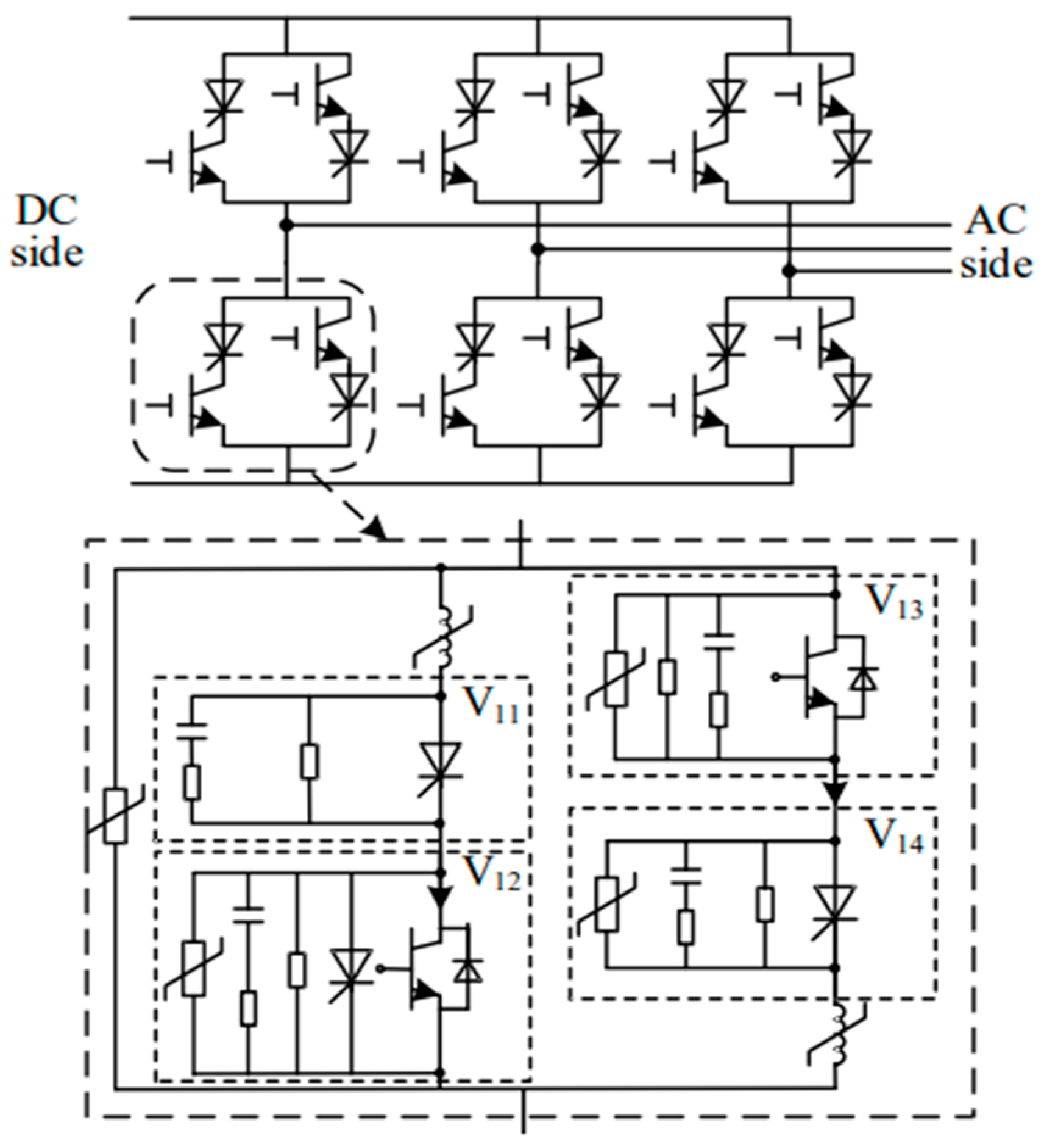
The electrical topology of a 6-pulse CLCC is shown in
Figure 1 [
21]. In this topology, each bridge arm (VT1–VT6) of the 6-pulse converter consists of a main branch and an auxiliary branch connected in parallel. Each valve unit (V) is composed of four submodules, denoted as V11–V14. Among them, V11 is a high-voltage, high-current thyristor valve, and V14 is a low-voltage, low-current thyristor valve. V12 is a low-voltage, high-current insulated gate bipolar transistor (IGBT) valve, while V13 is a high-voltage, low-current IGBT valve. The main current path is formed by submodules V11 and V12, whereas the auxiliary current path is formed by V13 and V14. The main thyristor valve V11 performs the same function as the thyristor valve in a conventional LCC. The fully controlled valve V12 is used to block the main branch during the commutation process, forcing the current to transfer to the auxiliary branch. This increases the turn-off time of the thyristor and ensures reliable recovery of its blocking capability. The IGBT in the auxiliary branch is then used to interrupt the bridge arm current, ensuring successful completion of the commutation process.
2.1.2. Operating Principle of CLCC
DC converters based on CLCC valves can operate in two modes: the conventional LCC mode and the CLCC mode [
22]. In CLCC mode, both the IGBT valves in the main branch and the auxiliary branch are activated, while the bypass thyristor valve in the main branch is blocked. Depending on the operating conditions, CLCC mode includes two sub-modes: normal commutation mode and forced commutation mode.
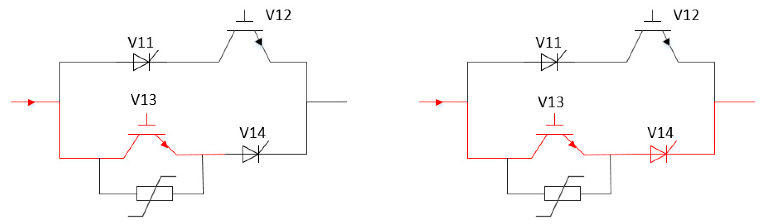
When a bridge arm receives a firing signal, the main branch thyristor valve V11, the IGBT valve V12, and the auxiliary IGBT valve V13 are triggered simultaneously. At this stage, the main branch conducts and carries the DC current. At 120°, the bridge arm enters the commutation process. For example, current is transferred from bridge arm 1 to bridge arm 3. During commutation, when the bridge arm current decreases to a certain level, the main branch IGBT valve V12 is turned off, and the auxiliary branch is turned on simultaneously. The current is then transferred from the main branch to the auxiliary branch. After commutation is completed, the current in the main branch falls to zero, and the thyristor valve V11 withstands reverse voltage and enters the blocking recovery period. After V12 is turned off, the auxiliary branch IGBT valve V13 is turned off with a delay of 500 to 1 ms, so that the auxiliary branch is blocked and the entire bridge arm regains its blocking capability.
Under normal operating conditions, from the perspective of the external circuit, the bridge arm current still follows the conventional natural commutation process. The only difference is that, in the later stage of commutation, the current is transferred from the main branch to the auxiliary branch. For the external circuit, the bridge arm can still be regarded as short-circuited during the commutation interval, as shown in
Figure 2.
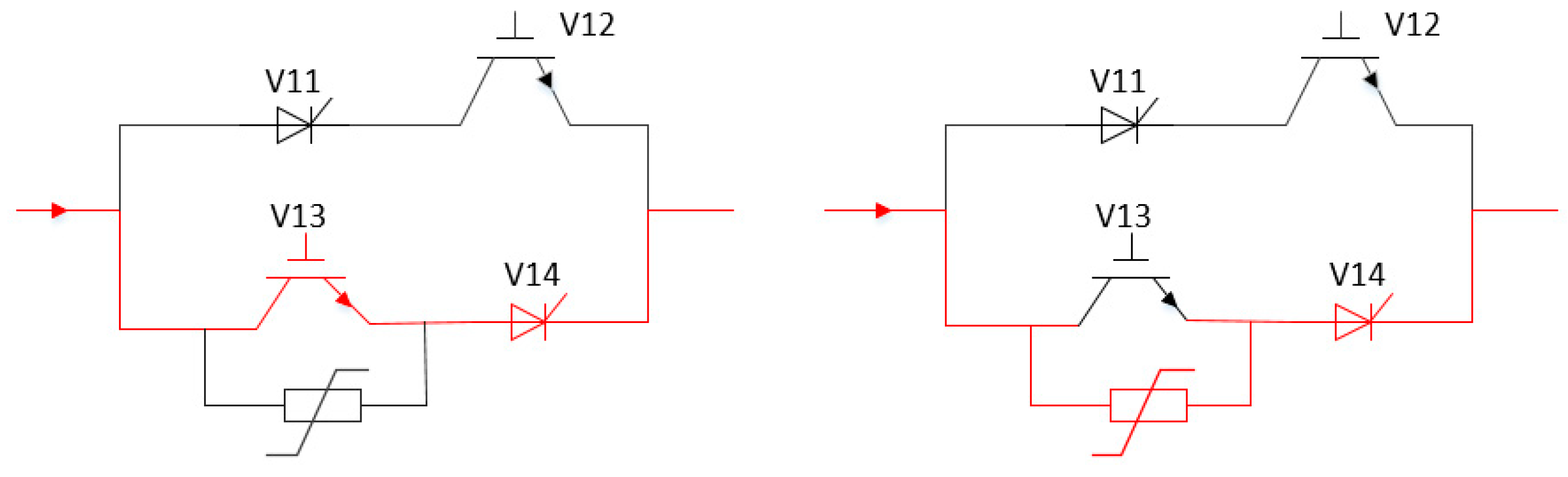
When an AC-side fault occurs, the CLCC valve operates in the forced commutation mode, and its operating principle is illustrated in
Figure 3. During the fault, natural commutation cannot be achieved due to insufficient commutation voltage. Therefore, during the commutation process, the main-branch IGBT valve is turned off, and the bridge arm current is transferred from the main branch to the auxiliary branch. Subsequently, the main thyristor valve current falls to zero and turns off. After the thyristor regains its blocking capability, the auxiliary-branch IGBT valve is turned off, forcing the current to transfer to the paralleling arrester. Then the arrester rapidly establishes a high operating voltage, which effectively enhances the commutation voltage and accelerates the commutation process. As a result, successful commutation between bridge arms is achieved, thereby avoiding commutation failure. The peak current in the auxiliary branch is typically less than twice the rated current. Considering the commutation duration between the main and auxiliary branches, as well as the recovery time of the main-branch thyristor, the conduction time of the auxiliary branch is generally limited to within 1 ms.
From the above process, it can be seen that once the bridge arm current is fully transferred from the main branch to the auxiliary branch, the main-branch thyristor valve V11 enters the reverse recovery stage. Before the auxiliary-branch IGBT valve V13 is turned off, V11 continuously withstands the reverse voltage provided after the turn-off of V12. The delay time between the turn-off of V12 and V13 can be flexibly defined by the valve control system. As long as this delay exceeds the required recovery time of the main thyristor valve V11, the blocking capability of the entire bridge arm can be reliably restored. Therefore, the commutation process of the bridge arm is fully controllable.
To further clarify the operating limits of the CLCC, its operation modes and the transition logic are fundamentally governed by the real-time AC voltage and commutation capability. The transition logic and reliability boundaries between natural commutation and forced commutation are detailed as follows:
The internal controller of the CLCC monitors the AC voltage and DC current in real time. Under steady-state conditions or minor AC grid faults, the commutation voltage area is sufficient to support the natural transfer of current before the extinction angle . In this case, the CLCC operates in the natural commutation mode to minimize losses. The critical condition for mode transition is defined by whether the predicted extinction angle is less than a predetermined safety threshold . Once is detected, the valve control system immediately switches to the forced commutation mode at a specific triggering instant, forcibly interrupting the main branch current using fully controlled devices;
During the forced commutation process, the turn-off delay time () of the auxiliary branch IGBT () must be strictly controlled within a bounded reliability window. It must strictly exceed the inherent recovery time () of the main thyristor () to ensure reliable blocking and prevent re-breakdown when the forward voltage is reapplied. Simultaneously, must not be excessively long; since the auxiliary branch is designed only for transient conduction, prolonged operation would induce severe thermal stress and on-state losses on the IGBTs, while also significantly increasing the energy dissipation burden on the paralleling arrester used for forced arc extinction. Typically, this delay is optimally configured between 500 ms and 1 ms to strike a crucial balance between ensuring reliable thyristor recovery and protecting the thermal stability of the devices.
2.2. Dynamic Reactive Power Support Mechanism and Control Strategy of CLCC
The core principle of dynamic reactive power support provided by CLCC lies in its ability to overcome the extinction angle limitation inherent in conventional converters. By increasing the firing angle (α) during transient conditions, the converter station can rapidly shift from consuming a large amount of reactive power to supplying reactive power. Specifically, under constant DC power, the reactive power consumed by the inverter decreases as the firing angle increases. However, LCC inverters rely heavily on the reverse voltage within the extinction angle to restore the blocking capability of thyristors. Increasing the firing angle in such systems reduces the extinction angle margin and can easily lead to commutation failure. As a result, the firing angle in LCC systems must be constrained within a limited range, leading to significant reactive power consumption. In contrast, due to its topology and forced commutation mechanism, CLCC eliminates the dependence of the turn-off process on reverse voltage. This allows the extinction angle to operate temporarily at zero or even negative values, fundamentally removing the risk of commutation failure. Based on this feature, when disturbances occur in the AC system, CLCC can increase the firing angle without being constrained by commutation failure. This reduces the converter station’s own reactive power consumption. Meanwhile, CLCC could inject reactive power into the AC grid within a short time, thereby injecting strong dynamic reactive power support.
2.2.1. Principle of Reactive Power Support in CLCC
Before deriving the mathematical expressions, it is necessary to establish the theoretical boundaries. To derive the analytical relationship between the reactive power and the firing angle, the following ideal assumptions are adopted to simplify the analysis:
The DC smoothing reactor is assumed to be sufficiently large, ensuring that the DC current remains constant and ripple-free during the entire commutation process;
The commutation process is assumed to be lossless. The active power losses of the converter transformer and the switching losses are neglected, considering only the commutation leakage reactance ();
The current and angles refer to the combined macroscopic state of the main and auxiliary branches, ignoring the internal transient current distribution between them;
The formulas focus purely on the fundamental frequency components, ignoring the impact of DC current harmonics that may be amplified during forced commutation.
It must be emphasized that the validity of these derived analytical formulas is restricted to the condition where the extinction angle . This boundary condition is necessary to avoid the complex scenario of handling double overlapping commutations within a single interval. Furthermore, the 6-pulse converter valves are assumed to conduct uniformly over one cycle.
Under these established boundaries, taking the commutation of current from valve 5 to valve 1 as an example, during natural commutation, the current of valve 1 can be expressed as:
Here, is the commutation reactance, is the RMS value of the secondary line voltage of the converter transformer, and α is the firing angle.
During forced commutation, the current of valve 1 is given by:
Here, Uar is the operating voltage of the arrester in submodule V13. If natural commutation is not completed, the forced commutation angle can be derived as:
By applying Fourier decomposition to the AC line current, the fundamental reactive component can be obtained as:
Thus, the reactive power Q can be expressed as:
It should be emphasized that Equation (5) represents the fundamental reactive power component consumed by the converter valves, derived via Fourier decomposition. This theoretical formulation explicitly neglects the reactive power compensated by the AC filter banks. Therefore, the primary validity and purpose of these formulas are to qualitatively reveal the dynamic trend and capability of the CLCC inverter to adjust its reactive power output by varying the firing angle.
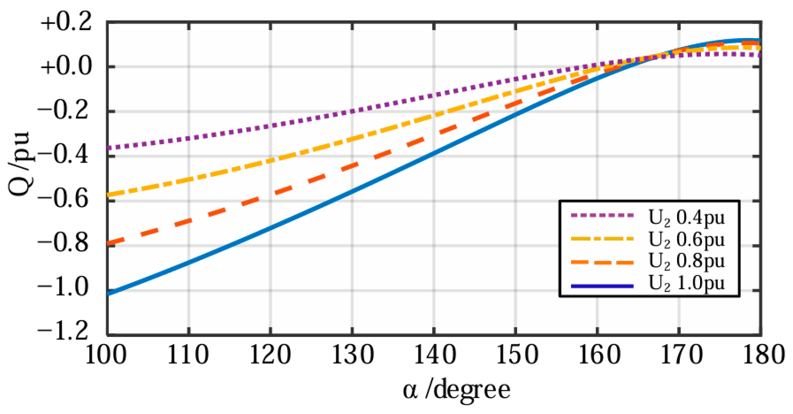
According to (5), neglecting the reactive power generated by the AC filter groups, the relationship between the reactive power output of the CLCC inverter and the firing angle α under different AC bus voltage levels is shown in
Figure 4 [
23]. When the firing angle α varies within the range of 140° to 180°, the reactive power of the CLCC inverter can vary from negative values (absorbing reactive power) to positive values (supplying reactive power). In particular, when α = 162°, the reactive power output of the CLCC inverter is zero.
2.2.2. Fixed AC Voltage Control Strategy of CLCC
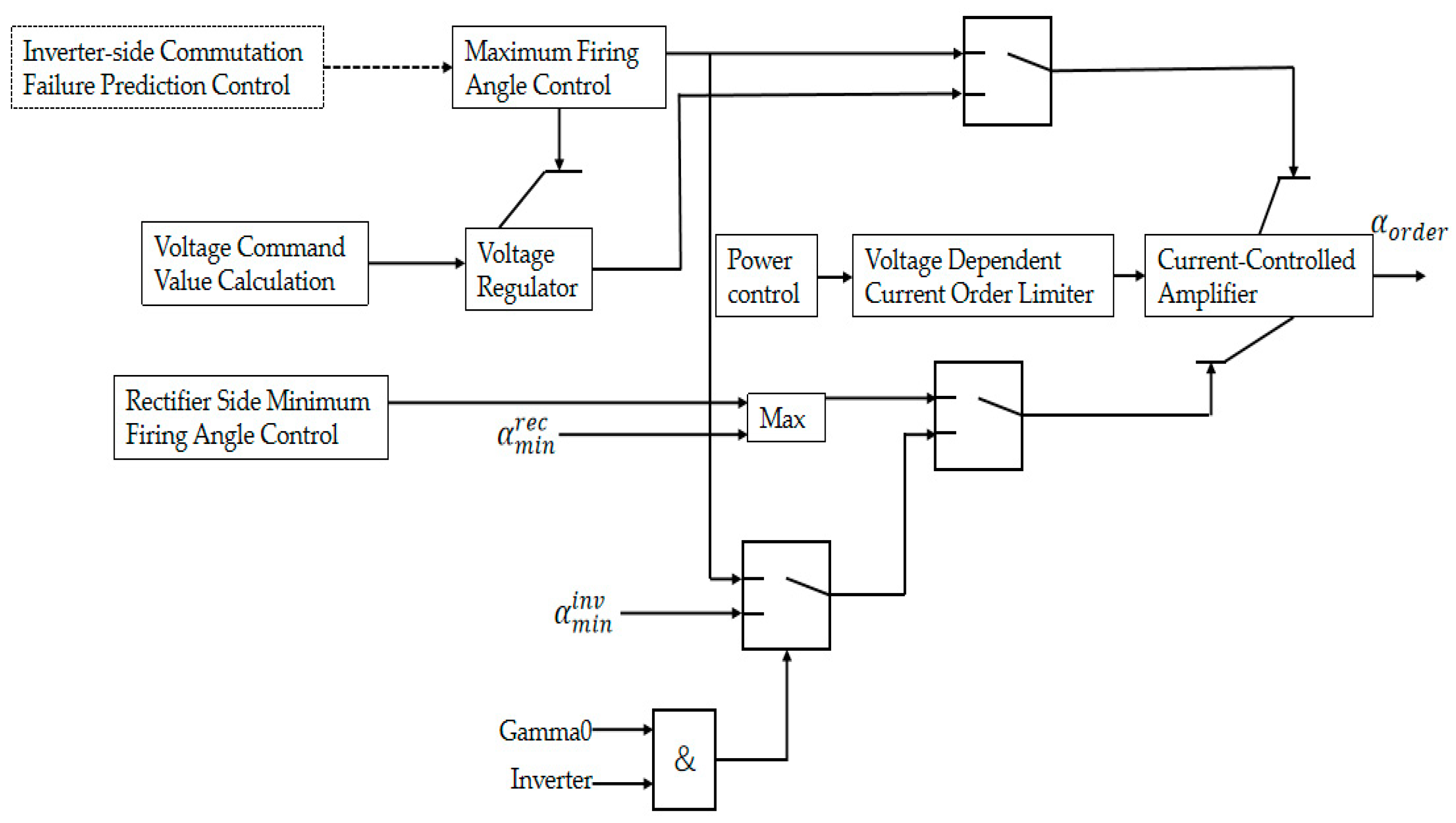
The control structure of the CLCC is shown in
Figure 5. Since CLCC can prevent commutation failure, it does not require commutation failure prediction. Under steady-state conditions, the rectifier-side LCC operates in fixed DC current control mode, while the inverter-side CLCC operates in fixed DC voltage control mode. When a fault occurs in the receiving-end AC system, the AC voltage (
) drops significantly. Due to the large voltage dip, even if the extinction angle is reduced to its minimum limit, the DC voltage cannot be maintained. The resulting decrease in DC voltage causes a rapid increase in DC current, which forces the rectifier, under constant DC current control, to significantly increase its firing angle to suppress the rectifier-side DC voltage [
24]. During the entire transient process, the conventional CLCC control strategy mainly focuses on maintaining the stability of DC-side electrical quantities. To further analyze the interaction between CLCC and the receiving-end AC system, and to fully exploit its reactive power regulation capability, this paper proposes to modify the outer-loop control of the inverter-side CLCC from fixed DC voltage control to fixed AC voltage control. This enables the converter station to output active dynamic reactive power support to the receiving-end grid.
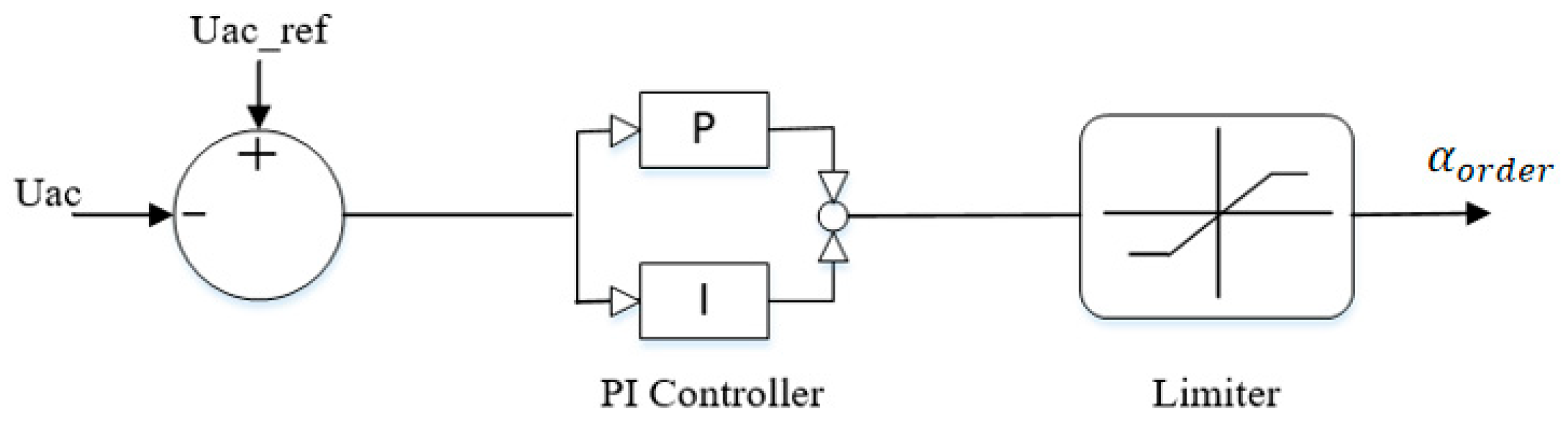
When a fault or severe disturbance occurs in the AC system, leading to a drop in Uac, the control system directly compares the measured AC bus voltage with the reference value Uac_ref. The resulting error signal is fed into the control loop. Based on the magnitude of the voltage deviation, the fixed AC voltage controller rapidly increases the firing angle command α. As α increases, the converter station quickly shifts from a steady-state condition of high reactive power consumption to a state of reactive power injection into the AC system. The reactive power provided by the CLCC directly compensates for the reactive power deficit during the fault, effectively restoring the AC bus voltage Uac. This forms a natural negative feedback mechanism, thereby enhancing the transient stability of the receiving-end AC/DC system. The voltage control logic is illustrated in
Figure 6.
Mathematically, the fixed AC voltage controller dynamically generates the firing angle command
based on the voltage deviation. The relationship can be expressed by the following Proportional-Integral (PI) control function:
where
and
are the proportional and integral gains of the PI controller, respectively. To ensure the stable operation of the converter and prevent over-regulation, a saturation limiter is applied to the output of the PI controller. The firing angle command is bounded by [
,
]. In this study,
is set to
to maintain a minimum margin for inverter operation, and
is limited to
to prevent voltage collapse and ensure smooth auxiliary branch commutation.
When drops below the reference during an AC grid fault, the positive error signal is amplified by the PI controller, rapidly driving toward its upper limit. This shift directly triggers the CLCC’s forced commutation mechanism, transforming the converter into a dynamic reactive power compensator until the AC voltage recovers and the error signal is eliminated.
2.3. CLCC Model Development and Validation
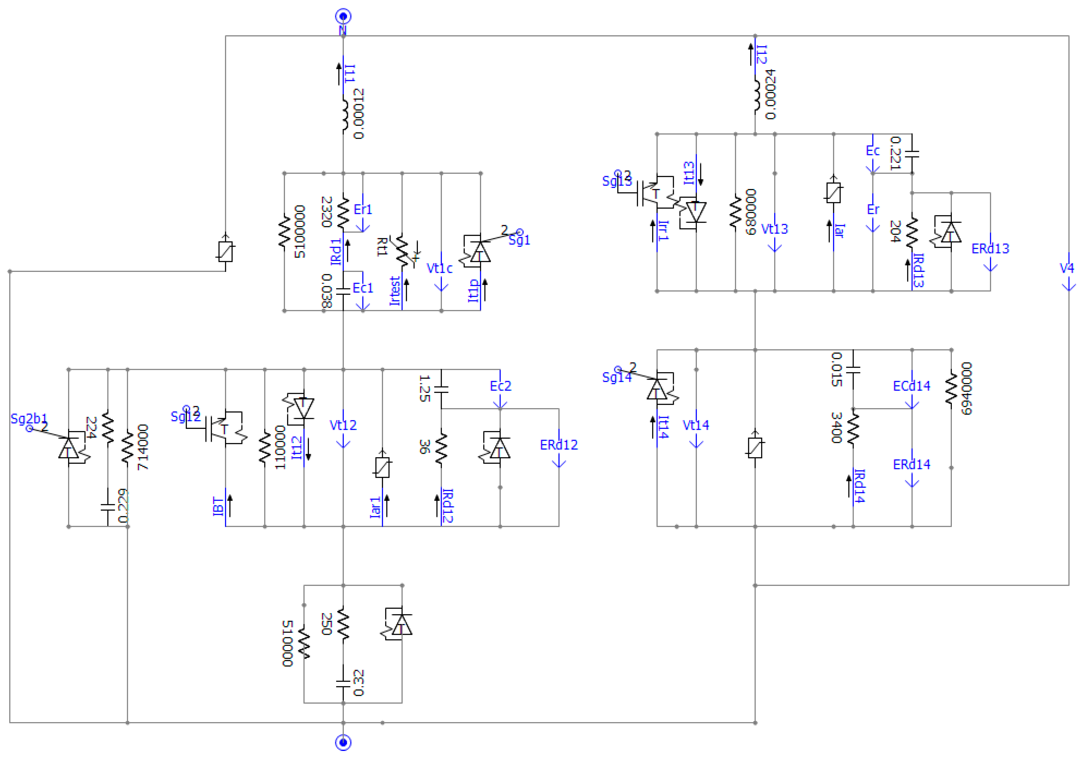
Based on the parameters of an actual converter station, a CLCC simulation model is built in PSCAD, as shown in
Figure 7.
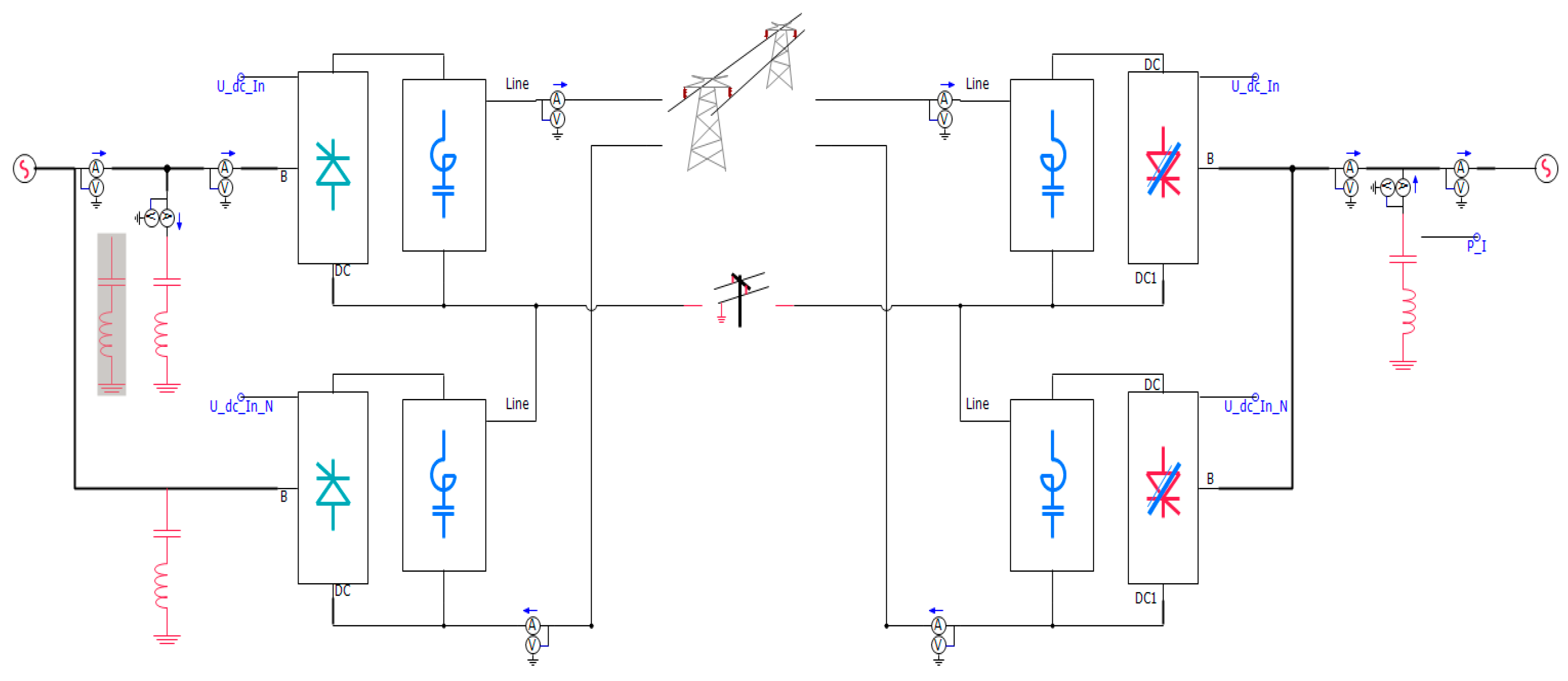
To verify the performance of the CLCC valve model, a benchmark simulation system is established in PSCAD based on the CIGRE benchmark model. In this system, equivalent AC networks are modeled for both the rectifier and inverter sides. The rectifier side employs the conventional LCC converter, while the inverter side adopts the CLCC valve model. The overall simulation model is shown in
Figure 8.
The main parameters of the benchmark LCC-CLCC HVDC system are presented in
Table 1. The electromagnetic transient simulation is conducted with a solution time step of 50
, and the total simulation duration is set to 0.9 s to fully capture the dynamic response characteristics during the fault and recovery periods.
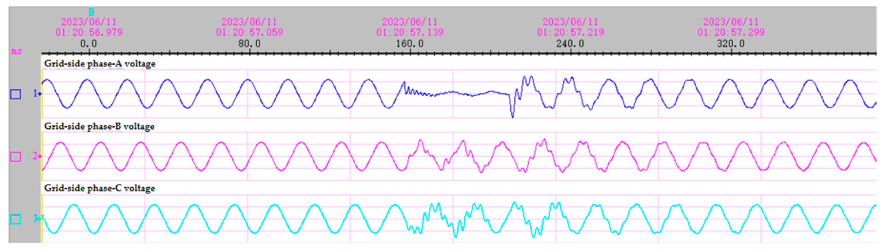
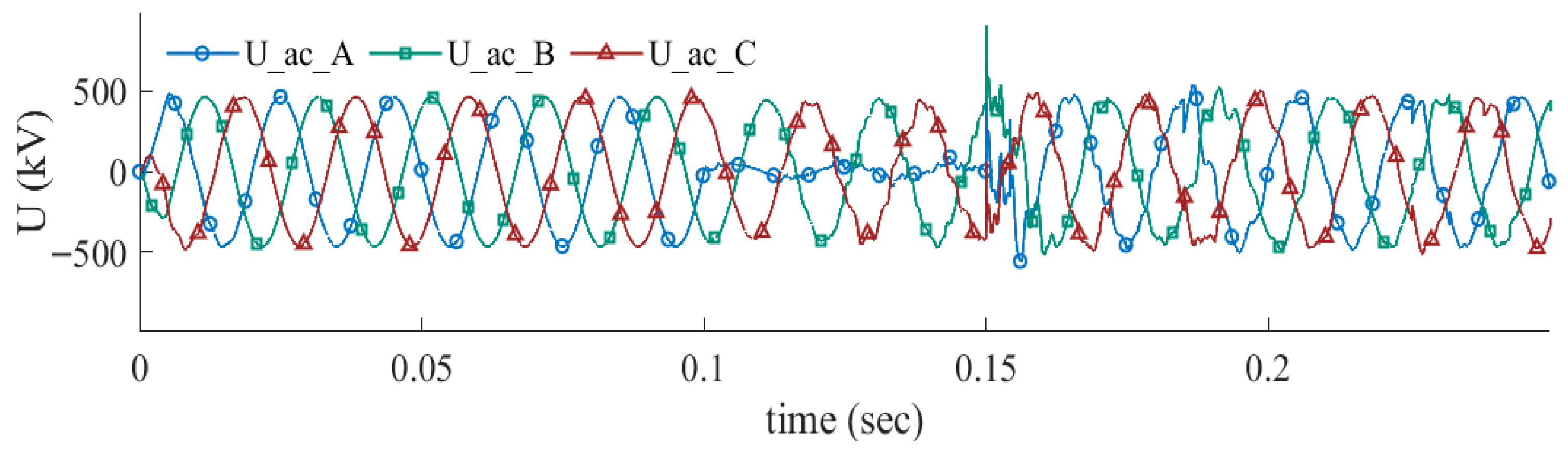
A single-phase-to-ground fault (phase A) is applied at the inverter-side AC bus. The fault occurs at 0.1 s and lasts for 0.15 s. The simulated AC voltage waveforms at the grid side are then compared with field-recorded waveforms obtained from the actual CLCC converter station, as shown in
Figure 9 and
Figure 10.
The comparison indicates that, under the phase-A single-line-to-ground fault, the simulated voltage waveforms are in good agreement with the measured results before and after the fault. Specifically, the voltage of the faulted phase (phase A) drops rapidly, while the peak voltages of the non-faulted phases (phases B and C) remain nearly unchanged, with only slight waveform distortion. After the faulted line is cleared, the voltage of the faulted phase quickly recovers, and the voltages of the non-faulted phases return to normal. To quantitatively validate the accuracy of the developed PSCAD model, specific performance metrics during the transient period were extracted and compared. During the single-line-to-ground fault, the measured field data indicates that the minimum voltage dip of the faulted phase reached about 12 kV, with a voltage recovery time (to 90% of nominal value post-fault) of 54 ms. In comparison, the simulation model yielded a minimum voltage dip of 15 kV and a recovery time of 50 ms. The absolute deviation in the residual voltage is merely 3 kV, and the absolute difference in recovery time is 4 ms. These results demonstrate that the CLCC simulation model built in PSCAD is capable of accurately reproducing the dynamic response characteristics of the actual CLCC system. Subsequently, the application effect of CLCC under fixed AC voltage control will be simulated under this model.
3. Results
3.1. Performance Evaluation of CLCC Under Three-Phase Short-Circuit Fault
To validate the theoretical analysis and the effectiveness of the proposed control strategy, a three-phase-to-ground fault scenario is designed in the PSCAD model. The fault is applied at the AC transmission line near the inverter station outlet. Specifically, the fault is initiated at exactly t = 0.3 s. The fault duration is set to 0.1 s, meaning the fault is completely cleared at t = 0.4 s. The total simulation time is run up to 0.9 s to fully observe the pre-fault steady state, the transient fault ride-through, and the post-fault recovery process. Simulations are conducted under both LCC and CLCC operating modes with identical fault conditions to directly compare their dynamic reactive power performance.
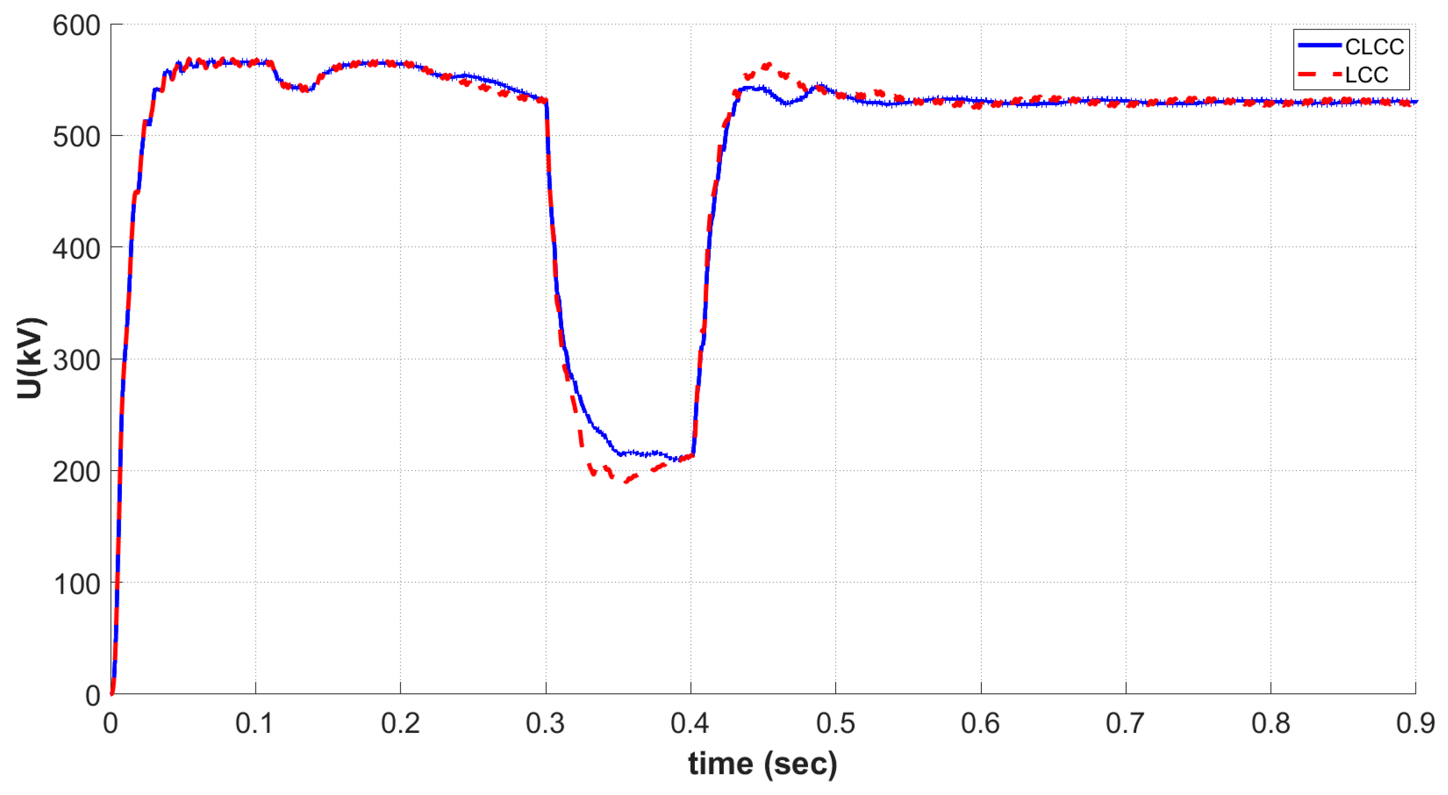
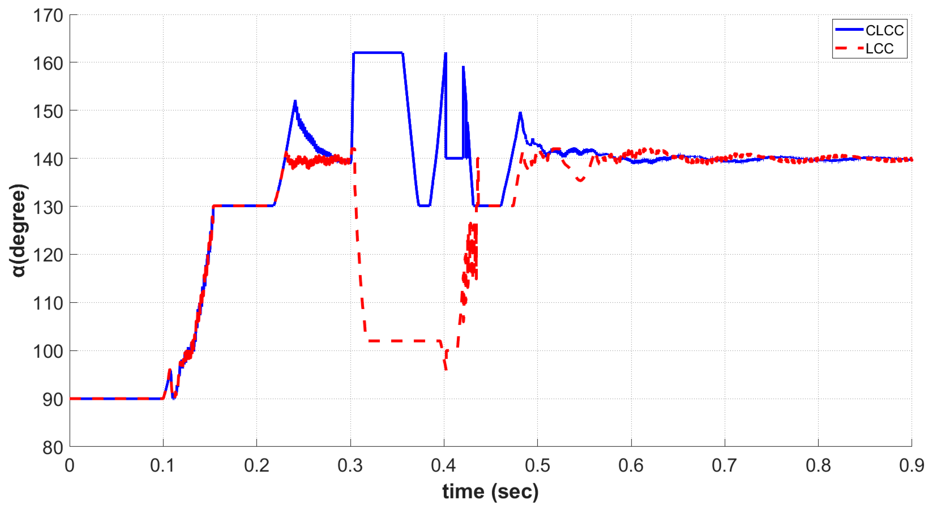
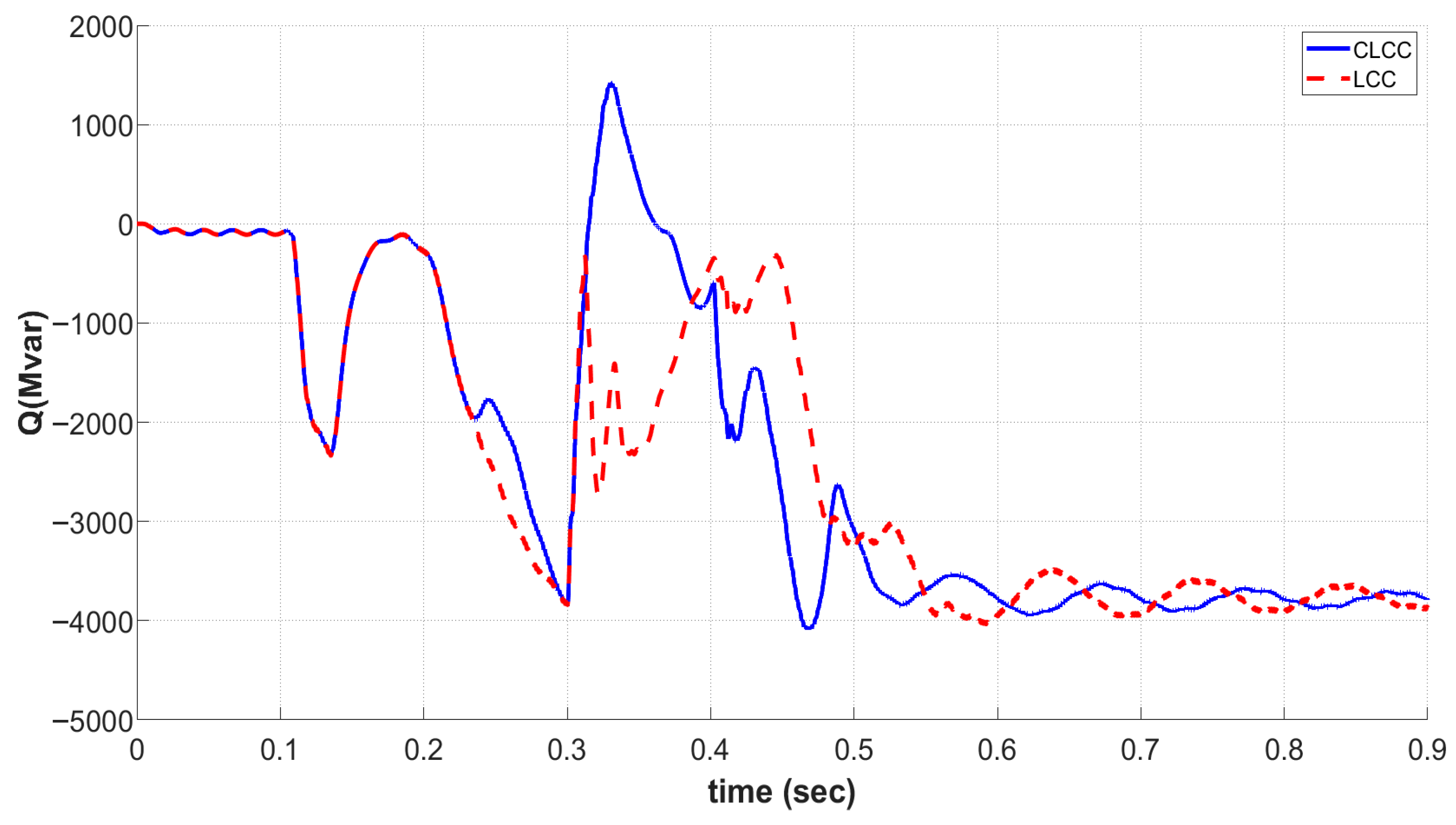
As shown in
Figure 11,
Figure 12 and
Figure 13, when a three-phase short-circuit fault occurs on the AC side, causing a sharp drop in bus voltage, the conventional LCC must significantly reduce the firing angle α to avoid commutation failure. To quantitatively evaluate the performance, specific indicators from the simulation are extracted. During the fault, the conventional LCC operation leads to a severe AC bus voltage drop to approximately 190 kV, with the reactive power absorption reaching at 3800 MVar. In contrast, under the fixed AC voltage control strategy, the CLCC actively increases the firing angle α to above 160° in response to the voltage drop. The increased firing angle not only prevents excessive reactive power absorption but also enables the converter to provide reactive power support reaching 1380 Mvar. Meanwhile, the AC filters at the converter station inject additional reactive power into the system. Consequently, the minimum AC bus voltage is maintained at a significantly higher level of 215 kV—an improvement of 13.15% over the LCC. Furthermore, during the post-fault recovery phase, the CLCC achieves a 90% voltage recovery in 12 ms, which is 8 ms faster than the LCC.
As a result, the voltage drop of the AC bus under CLCC operation is much smaller than that under LCC operation, and the voltage recovery trajectory remains consistently superior throughout the fault and post-fault period. The CLCC creates a synergistic effect with the reactive power continuously supplied by the AC filter banks. Therefore, compared with LCC, CLCC provides significantly enhanced voltage support during AC faults.
3.2. Performance Evaluation of CLCC Under Renewable Energy Scenarios
With the large-scale integration of renewable energy, the strong randomness and variability of wind power and other renewable sources often bring frequent and severe reactive power and voltage fluctuations in the AC grid. To evaluate the practical advantages of CLCC in power systems with renewable penetration, real measured wind power fluctuation data are incorporated into the developed LCC–CLCC hybrid AC/DC transmission system model for simulation analysis.
In this section, the CLCC operates under fixed AC voltage control, and real wind power fluctuations are used as system disturbances. The wind power fluctuation data utilized in these simulations are derived from real-world field measurements of a 300 MW wind farm. To evaluate the performance of CLCC, a highly volatile power sequence was selected, characterized by a maximum active power variation of 65% within 0.9 s. This specific profile represents extreme random conditions that typically induce severe reactive power absorption in the connecting grid. In the PSCAD, these active power sequences are implemented through the controlled current source model that is subject to external data control. Specifically, the real-world active power time-series data is directly imported into the simulation software (PSCAD 5.0.0) and utilized as the dynamic reference signal to drive the controlled current source. This approach ensures that the simulated wind farm accurately injects the corresponding fluctuating power into the receiving-end AC network, reproducing the fluctuations of renewable energy. The performance of CLCC and LCC is compared under both strong grid conditions and weak grid conditions, focusing on reactive power response, AC bus voltage variation, and dynamic adjustment of the firing angle.
3.2.1. Reactive Power Support Under Strong AC System Conditions
In this study, the strength of the AC grid is evaluated using the Short-Circuit Ratio (SCR). In the strong AC system scenario, the SCR is set to 6.8, which represents a highly stable grid capable of providing substantial voltage support.
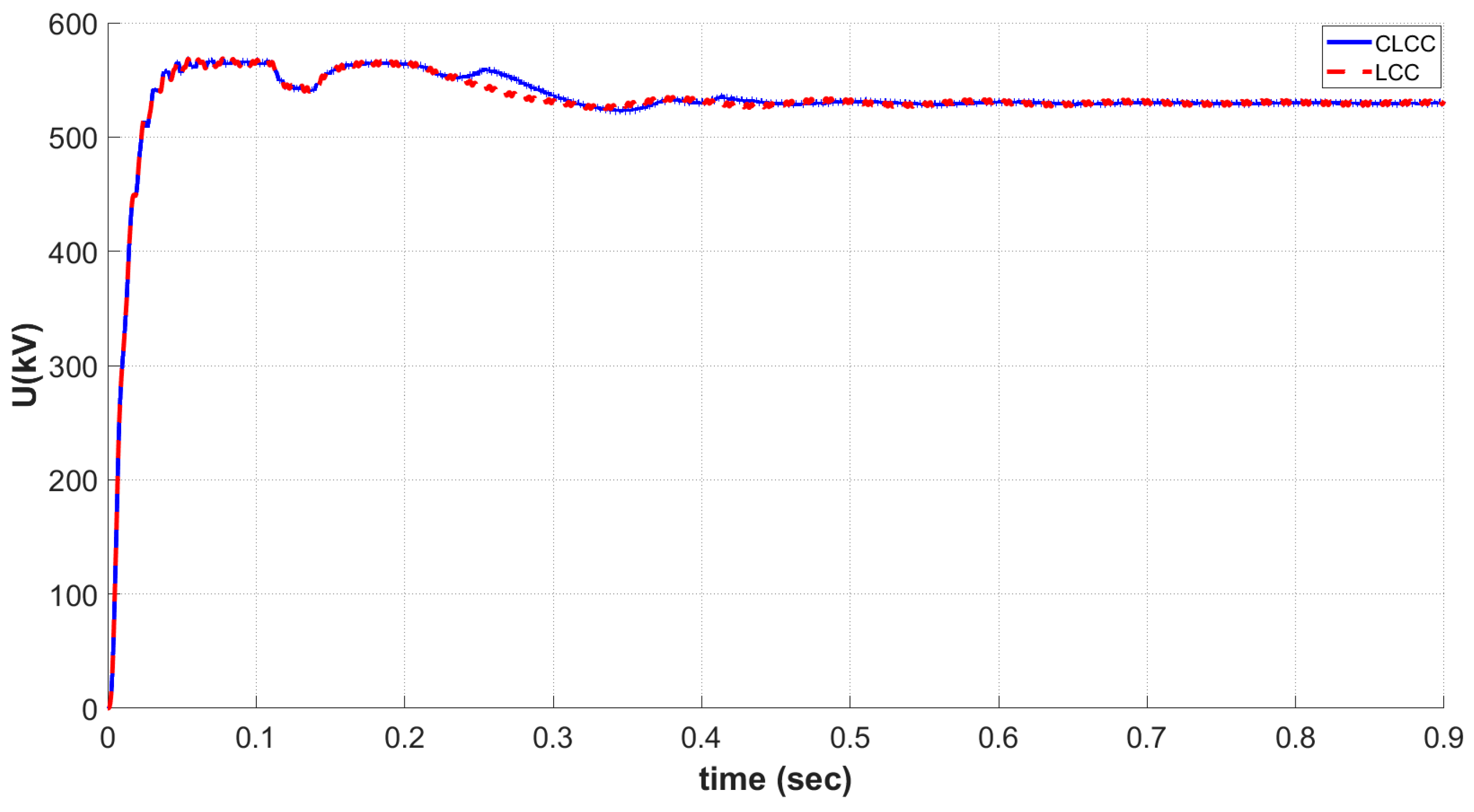
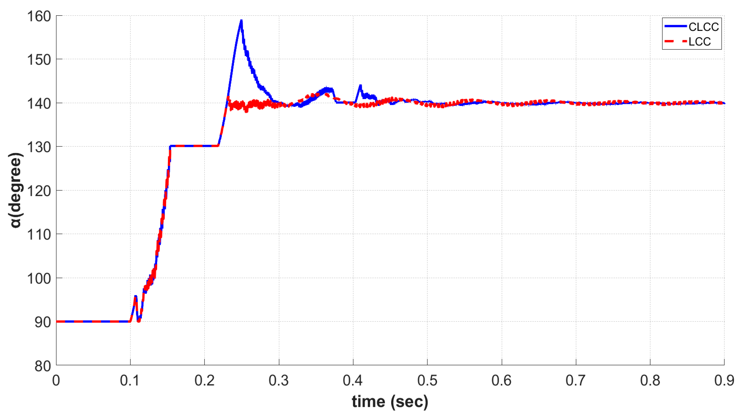
As shown in
Figure 14,
Figure 15 and
Figure 16, under strong grid conditions, the system has a high short-circuit capacity and exhibits relatively stable behavior. When large wind power fluctuations cause the system to absorb significant reactive power, the firing angle of CLCC can be observed to increase rapidly to approximately 160° at around 0.25 s. This increase in firing angle significantly reduces the reactive power absorbed by the converter, resulting in a noticeable reduction in the net reactive power consumption of CLCC. Compared with LCC, CLCC absorbs significantly less reactive power. However, benefiting from its fast dynamic reactive power compensation, CLCC exhibits a smoother voltage response during transient periods. This indicates that, in strong AC systems, the fixed AC voltage control of CLCC can respond quickly to disturbances and provide a certain buffering effect.
3.2.2. Reactive Power Support Under Weak AC System Conditions
A weak grid is characterized by a low short-circuit ratio, typically implying lower inertia and poorer voltage regulation capability. SCR < 2.0 is generally considered a weak grid. In the weak AC system scenario, the SCR is set to 1.5.
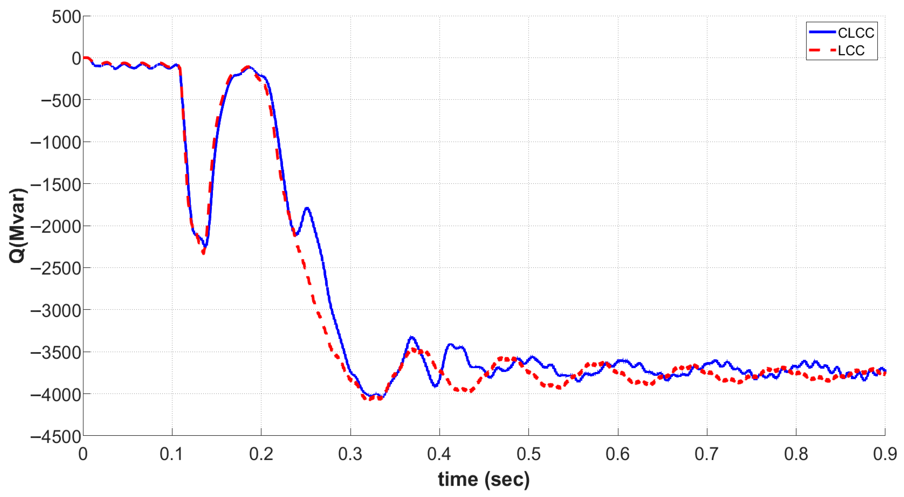
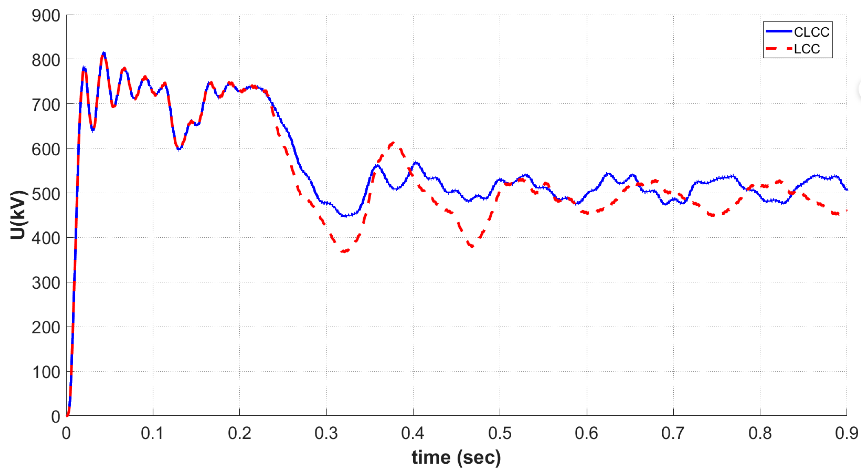
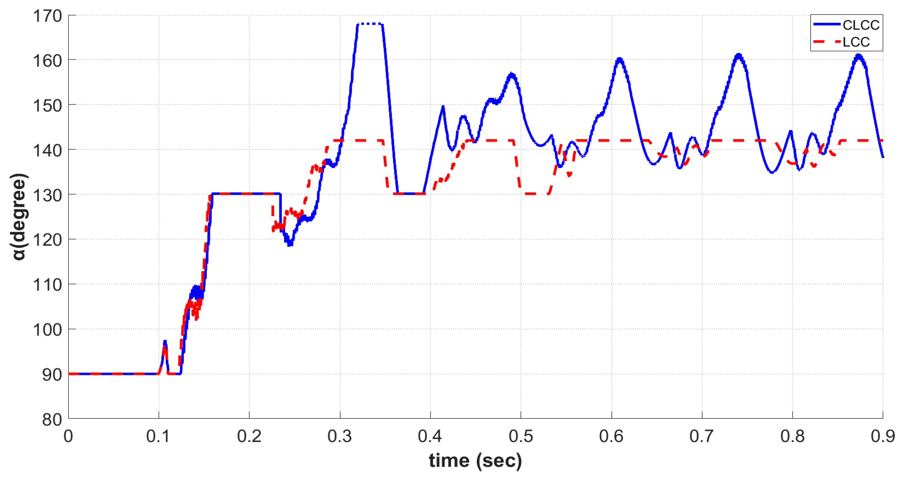
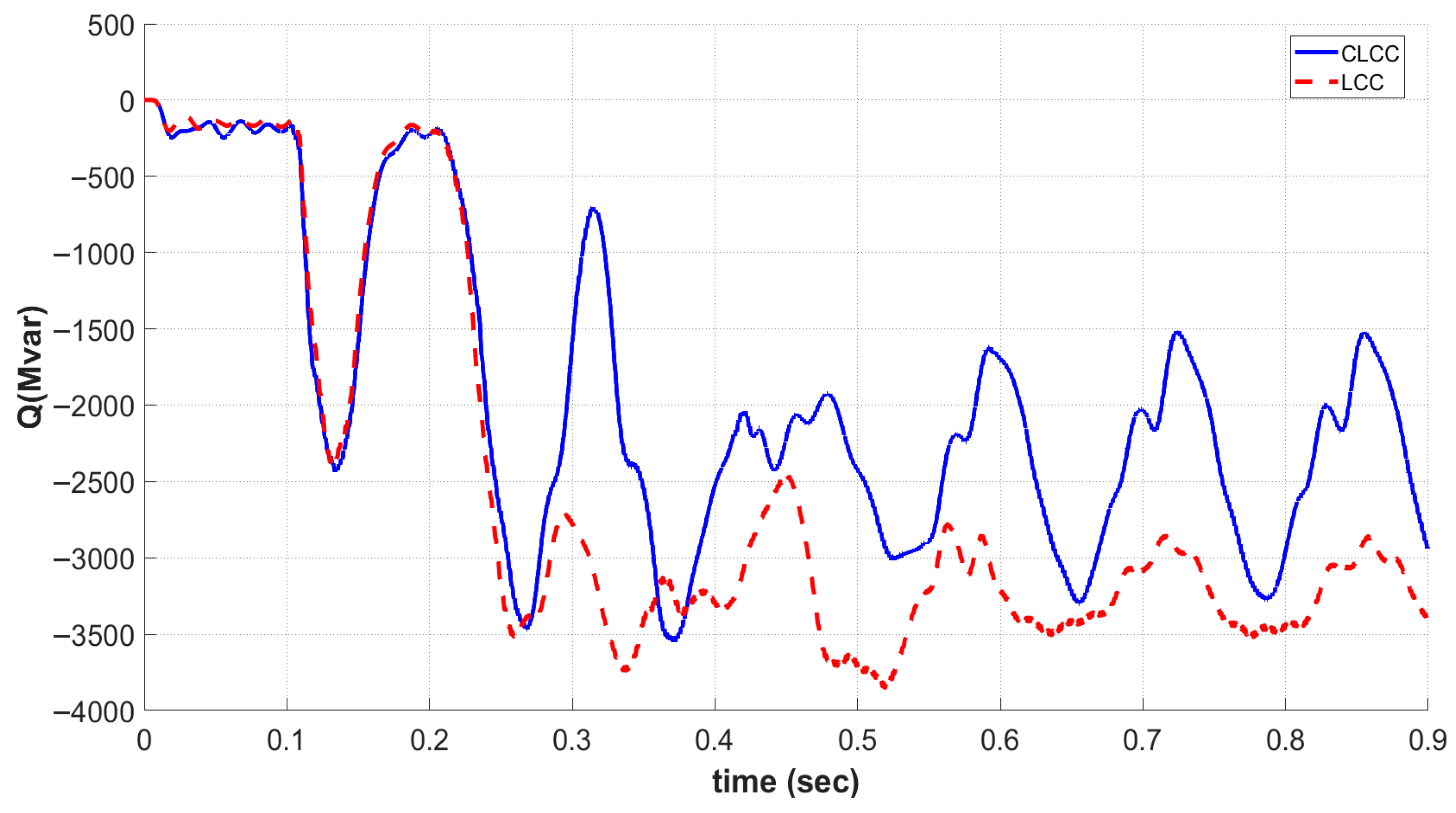
As shown in
Figure 17,
Figure 18 and
Figure 19, under weak grid conditions, the advantages of CLCC in reactive power support become more pronounced. Under continuous wind power fluctuations, the AC bus voltage experiences significant drops and oscillations. In this case, the LCC operation resulted in a severe maximum AC voltage sag to approximately 368 kV, accompanied by a peak reactive power consumption of 3794 MVar. In contrast, the CLCC under fixed AC voltage control restricted the maximum voltage sag to 447 kV—an improvement of 21.4% over the LCC. Concurrently, the CLCC limited its peak reactive power consumption to 3500 MVar. Due to the limitation of firing angle adjustment, the firing angle of LCC remains around 140° for most of the time, resulting in sustained high reactive power consumption and further aggravating the voltage instability. In contrast, CLCC fully utilizes its reactive power support capability. Its firing angle actively adjusts over a wide range in response to voltage fluctuations, frequently exceeding 160°. This significantly reduces the converter’s reactive power consumption and enables it to provide strong dynamic reactive power support to the system. As a result, this active reactive power intervention by CLCC effectively improves voltage quality in weak grids. From the AC voltage comparison curves, it can be clearly observed that the voltage drop under CLCC operation is much smaller than that under LCC operation. It is important to clarify that this improvement is a result of the dynamic coordination between control-level adjustments and hardware-level compensation. Under continuous wind power fluctuations, the wide-range
adjustment reduces the transmission system’s net reactive power deficit. This allows the existing AC filters to more effectively compensate for voltage fluctuations within the constraints of the weak grid’s parameters. Moreover, during the recovery process, the voltage trajectory of CLCC consistently remains at a higher and safer level than that of LCC.
4. Discussion
From the results under the different operating conditions, it is evident that CLCC and LCC exhibit significant differences in dynamic reactive power support capability. The reactive power exchange between the converter and the AC grid is mainly governed by the firing angle. For LCC, when wind power fluctuations lead to a decrease in AC voltage, the firing angle must be reduced to maintain sufficient commutation margin and avoid commutation failure. However, this increases reactive power consumption and further deteriorates the system voltage. In contrast, CLCC is not constrained by commutation failure and can increase the firing angle α. Under fixed AC voltage control, CLCC can actively and significantly adjust the firing angle in response to AC voltage fluctuations, thereby providing effective dynamic reactive power support. Therefore, in practical wind power integration scenarios, the CLCC demonstrates superior dynamic reactive power support capability. This advantage is particularly significant in weak grid conditions, where it greatly enhances voltage stability and disturbance resilience of the power system.
Despite these significant advantages, the practical implementation of CLCC faces several technical constraints and implementation challenges that must be explicitly acknowledged. First, the integration of fully controlled devices (IGBTs) in the auxiliary branches inherently increases the hardware complexity and capital cost of the converter station compared to traditional LCCs. Second, the forced commutation process relies heavily on the thermal capacity of the paralleled arresters and the auxiliary IGBTs. Because these components are designed to conduct for a very short duration, any malfunction in the valve control system or unexpected delays in trigger signals could lead to severe thermal stress or component damage.
Furthermore, from a broader system-level perspective, the proposed CLCC control approach must be contextualized alongside other dynamic voltage and reactive power support devices commonly used in AC systems, such as Static Synchronous Compensator (STATCOM), Static Var Compensator (SVC), and synchronous condenser. While the CLCC can provide reactive power support by timely adjusting the firing angle in response to variations in AC voltage, it also introduces challenges in control coordination. In grid scenarios where CLCC operates concurrently with STATCOMs or synchronous condensers, uncoordinated fast responses could potentially lead to reactive power overcompensation, or detrimental dynamic interactions. Therefore, a hierarchical or coordinated control strategy is imperative to allocate reactive power optimally between the CLCC and other grid-support equipment.
Previous research has mainly focused on analyzing the CLCC’s basic ability to prevent commutation failures. This paper takes a step further to explore its practical application and control method in the AC power grid. By changing to the fixed AC voltage control mode, the CLCC can actively adjust and output dynamic reactive power according to the actual needs of the AC system. As power systems integrate more renewable energy, the grid will face frequent and severe voltage fluctuations. The CLCC provides a feasible solution to fundamentally solve the commutation failure problem while maintaining the advantages of traditional LCCs. Future research could explore coordinated control methods between the CLCC and other equipment in the AC grid.
However, the findings of this study have certain limitations regarding their generalizability. The theoretical derivation of the reactive power relies on idealized assumptions, such as a strictly constant DC current and lossless commutation processes, which may introduce slight deviations under actual extreme transient conditions. Moreover, the simulation results are validated based on a point-to-point hybrid LCC-CLCC benchmark model under typical fault scenarios. The applicability of the proposed fixed AC voltage control strategy in more complex grid topologies such as offshore wind power integrations, remains to be further verified. Further studies could also evaluate the long-term performance of CLCCs in different complex renewable energy scenarios.
5. Conclusions
This paper presents a systematic theoretical analysis and simulation study on the dynamic reactive power support capability of the CLCC and its application performance. The main conclusions are summarized as follows:
By utilizing the coordinated operation of main and auxiliary branches with fully controlled devices, CLCC employs a forced commutation mechanism that removes the constraint of commutation failure during AC system disturbances. This allows CLCC to increase the firing angle, achieving a rapid transition from high reactive power consumption to reactive power injection, thereby providing dynamic reactive power support;
The proposed fixed AC voltage control strategy establishes a direct negative feedback relationship between the CLCC and the receiving-end AC voltage. When a sudden voltage drop is detected at the AC bus, the controller can promptly increase the firing angle, reducing the converter’s reactive power consumption and injecting dynamic reactive power into the grid. Compared with LCC, CLCC demonstrates a clear advantage in fault support capability;
In renewable energy integration scenarios, the dynamic regulation capability of CLCC is fully demonstrated. Especially in weak AC systems, under wind power fluctuations, the LCC is limited in its control range and tends to aggravate voltage instability. In contrast, CLCC can actively adjust the firing angle over a wide range (exceeding 160°), effectively reducing reactive power consumption, minimizing the depth of bus voltage drops, and maintaining the voltage at a higher and safer level.
Author Contributions
Conceptualization, formal analysis and validation, T.D. and W.Z.; data curation, Z.D.; investigation, G.Z.; methodology, T.D., W.Z., J.Z. and G.Z.; project administration, Z.D. and G.Z.; resources and software, Z.D. and J.Z.; supervision, W.Z. and G.Z.; visualization, J.Z.; writing—original draft and writing—review and editing, T.D. All authors have read and agreed to the published version of the manuscript.
Funding
This research was funded by the Science and Technology Project of State Grid Corporation of China (grant number: 52094024001T).
Data Availability Statement
The data that support the findings of this study are available from the corresponding author upon reasonable request.
Acknowledgments
The authors gratefully acknowledge the anonymous reviewers for their valuable feedback and expert recommendations.
Conflicts of Interest
Author Zhaoxin Du was employed by the State Grid Shanghai Municipal Electric Power Company. Author Jing Zhang was employed by the State Key Laboratory of Advanced Power Transmission Technology, State Grid Smart Grid Research Institute Co., Ltd. The remaining authors declare that the research was conducted in the absence of any commercial or financial relationships that could be construed as potential conflicts of interest. The authors declare that this study received funding from the State Grid Corporation. The funder was not involved in the study design; collection, analysis, or interpretation of the data; the writing of this article; or the decision to submit it for publication.
Abbreviations
The following abbreviations are used in this manuscript:
| CLCC | Controllable Line-Commutated Converters |
| LCC | Line-Commutated Converter |
| HVDC | High-Voltage Direct Current |
| IGBT | Insulated Gate Bipolar Transistor |
References
- Xi, H.; Tang, G.; Liu, J.; Wei, X.; Cha, K. Development of ±800 kV/4750 A UHVDC converter valve. Proc. CSEE 2012, 32, 15–22+5. [Google Scholar] [CrossRef]
- Wei, X.; Shan, Y.; Tang, X. Development status and trends of HVDC transmission technology. Proc. CSEE 2025, 45, 8937–8958. [Google Scholar] [CrossRef]
- Zhu, L.; Niu, C.; Wang, Z.; Chi, Y.; Jin, J.; Wang, X. A dynamic extinction angle compensation control method for suppressing continuous commutation failure. Proc. CSEE 2021, 41, 7621–7631. [Google Scholar] [CrossRef]
- Li, R.; Li, Y.; Chen, X. A control method for suppressing the continuous commutation failure of HVDC transmission. Proc. CSEE 2018, 38, 5029–5042. [Google Scholar] [CrossRef]
- Yin, W.; Yang, Z. Study on reactive power balance and compensation strategy for UHVDC project. High Volt. Eng. 2006, 32, 50–54. [Google Scholar]
- Chen, S.; Li, X.; Yu, J.; Li, T.; Lu, P.; Yin, Y. A method based on the sin-cos components detection mitigates commutation failure in HVDC. Proc. CSEE 2005, 25, 1–6. [Google Scholar] [CrossRef]
- Zhang, Y.; Lu, J.; Zhang, F.; Bi, A. Commutation failure prediction considering critical fault moment. Power Syst. Technol. 2021, 45, 4066–4075. [Google Scholar] [CrossRef]
- Bian, J.; Long, Z.; Wang, H.; Li, G.; Guo, J. Prediction and Suppression Strategy of Subsequent Commutation Failure for Hybrid Cascaded HVDC System Based on Commutation Voltage. High Volt. Eng. 2026, 52, 674–683. [Google Scholar] [CrossRef]
- Guo, C.; Liu, Y.; Zhao, C.; Wei, X.; Xu, W. Power component fault detection method and improved current order limiter control for commutation failure mitigation in HVDC. IEEE Trans. Power Deliv. 2015, 30, 1585–1593. [Google Scholar] [CrossRef]
- Zhou, H.; Yao, W.; Li, C.; Wen, J. A predictive voltage dependent current order limiter with the ability to reduce the risk of first commutation failure of HVDC. High Volt. Eng. 2022, 48, 3179–3189. [Google Scholar] [CrossRef]
- Guo, C.; Li, C.; Liu, Y.; Jiang, B.; Zhao, C.; Zhou, Q. A DC current limitation control method based on virtual-resistance to mitigate the continuous commutation failure for conventional HVDC. Proc. CSEE 2016, 36, 4930–4937. [Google Scholar]
- Yang, J.; Gao, C.; He, Z.; He, D.; Zhang, J. Dynamic performance of controllable line-commutated converter (CLCC) in HVDC systems with weak sending end AC network. In Proceedings of the 2023 IEEE 6th International Electrical and Energy Conference (CIEEC); IEEE: Hefei, China, 2023; pp. 4495–4499. [Google Scholar]
- Liu, H.; Sun, T.; Du, Z.; Pang, T.; Zhao, W. Characteristic modeling and short-circuit characteristics of a novel controllable line-commutated converter valve. Power Grid Clean Energy 2024, 40, 76–83. [Google Scholar]
- He, Z.; Zhang, J.; Gao, C.; Yang, J.; Wang, C. Study on reactive power characteristics and short-circuit current characteristics of controllable line-commutated converter. Power Syst. Technol. 2025, 49, 4888–4894. [Google Scholar]
- Hou, L.; Wei, Y.; Zhang, S.; Jiang, Q.; Hang, Y. Series voltage commutated converter and control method for suppressing HVDC commutation failure. Proc. CSEE 2018, 38, 6481–6490. [Google Scholar] [CrossRef]
- Deng, L.; Zhou, X.; Hong, L.; Chen, B.; Xia, H.; Yin, H.; Liu, Y.; Zhu, Y. A novel commutation failure suppression method for series voltage commutated converter. Proc. CSEE 2021, 41, 7304–7313. [Google Scholar] [CrossRef]
- Wang, Z.; Xia, C.; Lai, S.; Ji, H.; Zhou, Y.; Cai, H. Fault equivalent model of hybrid MMC non-blocking DC fault crossing. Electr. Power Eng. Technol. 2023, 42, 103–111. [Google Scholar]
- Tan, F.; Zhu, C.; Deng, K. Applicable to multilevel MMC-SVG simplified SVPWM method research. Zhejiang Electr. Power 2022, 9, 64–70. [Google Scholar] [CrossRef]
- He, Z.; Gao, C.; Ye, H.; Yang, J.; Wang, C.; Sheng, C. Development and engineering application of controllable line-commutated converter. Autom. Electr. Power Syst. 2024, 48, 181–191. [Google Scholar]
- Gao, C.; Sheng, C.; Wang, P.; Yang, J.; Li, J.; He, Z. Experimental study on controllable turn-off of controllable line-commutated converter valve and its engineering application. Power Syst. Technol. 2025, 49, 408–416. [Google Scholar]
- Gao, C.; Yang, J.; He, Z.; Tang, G.; Zhang, J.; Li, T.; He, D. Novel controllable line-commutated converter for eliminating commutation failures of LCC-HVDC system. IEEE Trans. Power Deliv. 2023, 38, 255–267. [Google Scholar] [CrossRef]
- Cai, L.; Li, J.; Zhang, K.; Xu, T. Experimental study on operation of controllable line-commutated converter. Power Electron. 2025, 59, 9–12+29. [Google Scholar] [CrossRef]
- Yang, J.; Gao, Y.; Zhang, J.; Yu, L.; Kou, L.; Gao, Y. Reactive power support control strategy and dynamic simulation test of controllable line-commutated converter. High Volt. Eng. 2026, 1–11. [Google Scholar] [CrossRef]
- Gao, C.; He, Z.; Yang, J.; Sheng, C.; Zhang, J.; Wang, P. Novel controllable grid-commutated converter topology and its control method. Proc. CSEE 2023, 43, 1940–1950. [Google Scholar] [CrossRef]
Figure 1.
Schematic diagram of 6-pluse CLCC.
Figure 1.
Schematic diagram of 6-pluse CLCC.
Figure 2.
Natural commutation phase of CLCC converter.
Figure 2.
Natural commutation phase of CLCC converter.
Figure 3.
Forced commutation phase of CLCC converter.
Figure 3.
Forced commutation phase of CLCC converter.
Figure 4.
Reactive power variation with firing angle under different AC voltages.
Figure 4.
Reactive power variation with firing angle under different AC voltages.
Figure 5.
Basic control structure diagram of CLCC.
Figure 5.
Basic control structure diagram of CLCC.
Figure 6.
Voltage regulator of CLCC.
Figure 6.
Voltage regulator of CLCC.
Figure 7.
PSCAD model of the CLCC converter valve.
Figure 7.
PSCAD model of the CLCC converter valve.
Figure 8.
Hybrid LCC–CLCC HVDC transmission system model in PSCAD.
Figure 8.
Hybrid LCC–CLCC HVDC transmission system model in PSCAD.
Figure 9.
Measured grid-side voltage waveform under fault conditions.
Figure 9.
Measured grid-side voltage waveform under fault conditions.
Figure 10.
Simulated grid-side voltage waveform under fault conditions.
Figure 10.
Simulated grid-side voltage waveform under fault conditions.
Figure 11.
Comparison of AC-side voltages of CLCC and LCC under three-phase short-circuit fault.
Figure 11.
Comparison of AC-side voltages of CLCC and LCC under three-phase short-circuit fault.
Figure 12.
Comparison of firing angles of CLCC and LCC under three-phase short-circuit fault.
Figure 12.
Comparison of firing angles of CLCC and LCC under three-phase short-circuit fault.
Figure 13.
Comparison of reactive power output of CLCC and LCC under three-phase short-circuit fault.
Figure 13.
Comparison of reactive power output of CLCC and LCC under three-phase short-circuit fault.
Figure 14.
Comparison of AC-side voltages of CLCC and LCC.
Figure 14.
Comparison of AC-side voltages of CLCC and LCC.
Figure 15.
Comparison of firing angles of CLCC and LCC.
Figure 15.
Comparison of firing angles of CLCC and LCC.
Figure 16.
Comparison of reactive power output of CLCC and LCC.
Figure 16.
Comparison of reactive power output of CLCC and LCC.
Figure 17.
Comparison of AC-side voltages of CLCC and LCC.
Figure 17.
Comparison of AC-side voltages of CLCC and LCC.
Figure 18.
Comparison of firing angles of CLCC and LCC.
Figure 18.
Comparison of firing angles of CLCC and LCC.
Figure 19.
Comparison of reactive power output of CLCC and LCC.
Figure 19.
Comparison of reactive power output of CLCC and LCC.
Table 1.
Main parameters of the simulated CLCC-HVDC system.
Table 1.
Main parameters of the simulated CLCC-HVDC system.
| Parameter | Rectifier Side | Inverter Side |
|---|
| AC voltage (kV) | 536 | 528 |
| Converter transformer leakage reactance (%) | 18 | 18 |
| Firing angle /Extinction angle (°) | 16 | 17 |
| DC voltage (kV) | 800 | 800 |
| DC current (A) | 5000 | 5000 |
| Smoothing reactor inductance (H) | 15 | 15 |
| Disclaimer/Publisher’s Note: The statements, opinions and data contained in all publications are solely those of the individual author(s) and contributor(s) and not of MDPI and/or the editor(s). MDPI and/or the editor(s) disclaim responsibility for any injury to people or property resulting from any ideas, methods, instructions or products referred to in the content. |