Article

Pore-Scale Oil Mobilization Mechanisms During Water-Alternating-CO2 Miscible Flooding in Low-Permeability Carbonate Reservoirs


1
Petroleum Exploration and Production Research Institute, Sinopec, Beijing 102206, China
2
Research Institute of Petroleum Exploration and Development, PetroChina, Beijing 100083, China
3
State Key Laboratory of Petroleum Resources and Engineering, China University of Petroleum (Beijing), Beijing 102249, China
*
Author to whom correspondence should be addressed.
Energies 2026, 19(10), 2401; https://doi.org/10.3390/en19102401
Submission received: 3 April 2026 / Revised: 13 May 2026 / Accepted: 14 May 2026 / Published: 16 May 2026
(This article belongs to the Section H1: Petroleum Engineering)

Abstract

To address the scientific challenges associated with complex microscopic pore structures and the unclear mechanisms of miscible gas injection in typical low-permeability carbonate reservoirs in the Middle East, online nuclear magnetic resonance (NMR) imaging experiments were conducted during water-alternating-CO2 miscible flooding. The microscopic oil mobilization mechanisms were quantitatively investigated for different pore structure types and at various displacement stages. The results indicate that water-alternating-CO2 miscible flooding achieves a relatively high degree of oil mobilization in large and medium pore–throat structures. This behavior is likely associated with Jamin-type flow resistance effects and flow regulation induced by gas–water alternating slugs. Differences in microscopic oil mobilization are mainly observed in mesopores (0.3–1.5 μm). The recovery degrees of mesopores in Cores 1, 2, and 3 reach 89%, 94.2%, and 78%, respectively, contributing 93.7%, 80.6%, and 50.9% to the total oil recovery. The degree of microscopic heterogeneity controls the distribution of remaining oil in core slices after breakthrough of the displacement front. In Core 1, the signal amplitude exhibits a gradual and uniform decline, indicating that gas–water alternating injection suppresses gas channeling and improves mobility control. In Core 2, the signal amplitude decreases more rapidly with increasing heterogeneity. In Core 3, the signal disparity continues to intensify, leading to the formation of dominant gas–water channeling pathways, while low-permeability pore–throat structures evolve into typical bypassed oil zones. As the CO2–oil contact front progressively advances toward the outlet end, the swept volume gradually decreases due to the development of preferential flow channels. Consequently, significant remaining oil accumulation occurs near the outlet region.

1. Introduction

Marine carbonate reservoirs occupy a pivotal position in the global energy landscape, contributing approximately 60% of the world’s annual oil and gas production. By the end of 2021, the remaining recoverable oil reserves in the Middle East amounted to 113.2 billion tons, accounting for 48.3% of the global total, indicating significant potential for enhanced oil recovery (EOR). This holds great strategic importance for implementing the “Belt and Road” national initiative and mitigating energy supply risks [1,2,3,4,5]. To address the challenges associated with complex multimodal pore structures and strong reservoir heterogeneity in typical low-permeability carbonate reservoirs in the Middle East, early-stage efforts have focused on differential well pattern reorganization and water and gas injection strategies to achieve rapid production enhancement. However, hidden interlayers and high-permeability zones have led to inefficient fluid flow during water and gas injection, limiting areal and vertical sweep efficiency [6,7,8]. Field practices have demonstrated that CO2–water alternating miscible flooding serves as an effective approach to mitigate uneven production profiles and achieve more balanced and efficient reservoir development in carbonate reservoirs [9,10,11,12,13].
Previous studies have extensively investigated CO2 injection for enhanced oil recovery (EOR) and shown that compared with conventional water flooding, CO2 flooding offers significant advantages. Through physicochemical mechanisms such as miscible extraction, oil viscosity reduction due to CO2 dissolution, oil swelling, and acidic dissolution, CO2 injection effectively improves oil recovery performance in carbonate reservoirs [14,15,16,17,18]. Furthermore, in the context of carbon neutrality, CO2 flooding also represents an economically sustainable approach to reducing greenhouse gas emissions [19,20,21]. Based on reservoir pressure (P) relative to the minimum miscibility pressure (MMP) of CO2–oil systems, CO2 flooding can be classified into miscible flooding (P ≥ MMP) and immiscible flooding (P < MMP). During the miscible flooding process, CO2 becomes fully miscible with crude oil, forming a single-phase miscible zone. In this region, the oil–gas interfacial tension is reduced to near zero, theoretically achieving a displacement efficiency of over 90% [22,23,24,25]. Both laboratory experiments and field trials have demonstrated that miscible flooding achieves higher oil recovery than immiscible flooding. However, in highly heterogeneous reservoirs, supercritical CO2 tends to cause viscous fingering along high-permeability layers, which limits the macroscopic sweep efficiency of the reservoir. Water-alternating-CO2 miscible flooding, by optimizing development parameters such as the gas–water slug ratio, gas injection rate, and liquid production rate, can not only mitigate gas channeling but also enhance oil displacement efficiency through CO2 miscibility, thus demonstrating great potential for widespread application [26,27,28,29,30]. Li et al. investigated the gas–water alternating injection process in heterogeneous porous media through core flooding experiments and found that this injection method significantly improved displacement efficiency in low-permeability regions. They also observed that increasing the number of gas–water alternating cycles enhanced both oil recovery and CO2 storage efficiency [31]. Khan et al. established 2D and 3D sector models for high-resolution compositional simulation, employing tuned equations of state to describe fluid properties [32]. They compared the performance of water-alternating-CO2 miscible flooding in homogeneous and heterogeneous reservoirs. Their results demonstrated that compared with homogeneous reservoirs, heterogeneous reservoirs exhibited a faster production response to WAG miscible flooding but achieved a lower expected ultimate recovery (EUR), earlier gas breakthrough, and higher gas–oil ratio (GOR) and water cut. Investigating the microscopic oil mobilization mechanisms during water-alternating-CO2 miscible flooding in highly heterogeneous reservoirs is essential for formulating appropriate development strategies and enhancing oil recovery.
However, conventional core flooding experiments cannot capture pore-scale fluid flow behavior [33,34]. As a non-destructive detection technique, nuclear magnetic resonance (NMR) enables a quantitative characterization of fluid distribution and oil mobilization features at different displacement stages by measuring the relaxation behavior of hydrogen nuclei in pore fluids and calibrating NMR T2 spectra with data from mercury injection capillary pressure (MICP) or nitrogen adsorption measurements [35,36,37,38]. Yakov et al. reported a linear relationship between NMR T2 distribution and pore–throat distribution [39]. Wang et al. characterized the pore structures of tight sandstone reservoirs in the Yanchang Formation of the Ordos Basin using NMR and MICP combined with fractal theory [40]. Their study revealed that the relationship between T2 and pore–throat radius better conforms to a power-law function rather than a linear correlation. Importantly, this calibration approach assumes equivalence between the pore radius and throat radius without distinguishing between them, whereas in actual reservoirs, the pore radius and throat radius can differ significantly.
Nevertheless, a quantitative pore-scale evaluation of oil mobilization behavior during water-alternating-CO2 miscible flooding in heterogeneous low-permeability carbonate reservoirs remains insufficient. In particular, the dynamic recovery contribution of different pore–throat scales and the influence of pore-structure heterogeneity on microscopic displacement behavior have not been fully clarified.
This paper focuses on typical low-permeability carbonate reservoirs in the Middle East. High-temperature and high-pressure online NMR scanning experiments were conducted during water-alternating-CO2 miscible flooding on actual core samples to quantitatively investigate the pore-scale oil displacement mechanisms, microscopic oil mobilization behavior, and recovery contribution across different pore–throat scales. The paper is organized as follows. (1) First, there is a classification of pore structure types and characteristics of carbonate rocks based on sedimentation–diagenesis and pore–throat parameters. (2) Next, we examine the implementation of high-temperature and high-pressure online NMR imaging experiments during water-alternating-CO2 miscible flooding on representative cores, integrating NMR scanning with MICP tests. (3) Afterwards, we establish the conversion relationship between the NMR T2 values and pore–throat radius to analyze oil mobilization mechanisms in pores of different scales and explore the influence of pore structure heterogeneity. (4) Next, we characterize the displacement front advancement and evolution during water-alternating-CO2 miscible flooding using one-dimensional frequency encoding and NMR imaging data. (5) Last, we summarize the main findings.

2. Classification of Pore Structure Types in Rocks

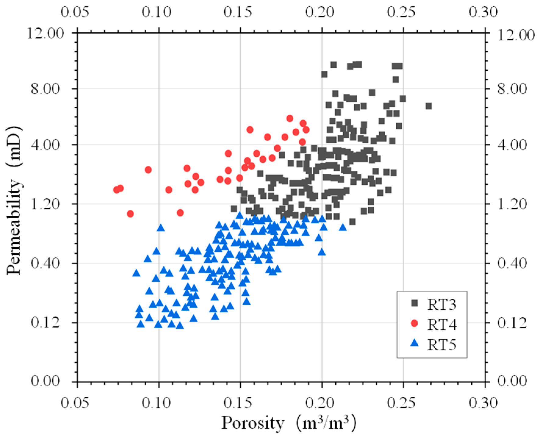
The target reservoir in this paper is a marine low-permeability carbonate reservoir in the Middle East. Early-stage development through differentiated water and gas injection strategies has achieved favorable production performance. However, challenges persist during injection, including severe gas–water channeling, uneven production profiles, and rapid water cut increase. The reservoir is predominantly composed of micritic limestone and grain limestone, which have undergone various diagenetic alterations—such as compaction, cementation, and dissolution—under different sedimentary conditions. It belongs to a matrix-pore type reservoir with generally underdeveloped natural fractures. Figure 1 shows the core porosity–permeability relationship for the target area. The results indicate that the pore structure and flow capacity exhibit significant spatial heterogeneity with permeability varying by several orders of magnitude under similar porosity conditions. This suggests that the heterogeneous distribution of pore–throat structures is a key factor controlling fluid flow capacity in marine carbonate reservoirs.
Based on the sedimentary and diagenetic characteristics, pore–throat radius distribution, displacement pressure, porosity, and permeability, the pore structures of the target low-permeability carbonate reservoir are classified into three types. The parameter ranges defining these pore structure types are presented in Table 1. The results indicate that different rock types exhibit significant variations in pore–throat radius distribution, displacement pressure, and flow capacity. An overall evolutionary trend is observed from larger pore–throats with better connectivity to progressively smaller pore–throats with stronger flow constraints. To investigate the influence of pore structure heterogeneity on microscopic oil mobilization during water-alternating-CO2 miscible flooding, one representative core was selected for each rock type (RT3, RT4, and RT5) based on typical pore–throat distribution characteristics and petrophysical properties. These samples were subsequently used in high-temperature and high-pressure online NMR experiments. It should be noted that the present results are intended to provide representative mechanistic observations for different rock types rather than statistically exhaustive conclusions.

3. Water-Alternating-CO2 Miscible Flooding Experiments

3.1. Core Samples

The core samples used in this paper were obtained from a typical low-permeability carbonate reservoir in the Middle East with an original reservoir temperature of 121 °C and a pressure of 21 MPa. Based on the previously established pore structure classification criteria, one representative core sample was selected for each of the three carbonate rock types (RT3, RT4, and RT5) according to typical pore–throat distribution characteristics, porosity, permeability, and displacement–pressure features. These samples were used to conduct combined online NMR and MICP measurements during water-alternating-CO2 miscible flooding under reservoir conditions. The porosity and permeability of the core samples are listed in Table 2. The experimental fluids were prepared according to the fluid properties of the target reservoir. To better reproduce the reservoir-condition fluid behavior under experimental temperature and pressure conditions, the experimental oil was prepared by reconstituting formation crude oil with kerosene, resulting in a density of 0.655 g/cm3 and a viscosity of 0.35 mPa·s. Slim-tube experiments were subsequently conducted to determine the MMP between CO2 and the recombined oil system, yielding a value of 21.8 MPa. The experimental brine was formulated to match reservoir conditions with a salinity of 273,063 mg/L; its ionic composition is provided in Table 3.

3.2. Experimental Setup

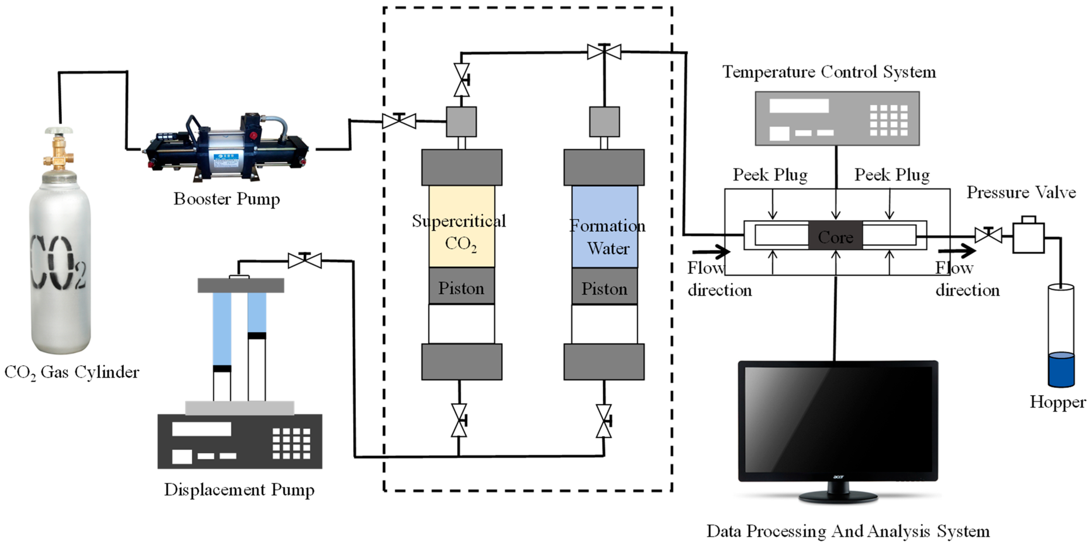
The water-alternating-CO2 miscible flooding experiments were conducted using a high-performance large-bore magnetic resonance imaging (MRI) system (model: LIME-MRI-D12). The system is highly integrated with a magnetic field strength of 0.3 ± 0.03 T and a field homogeneity of ≤50 ppm. Equipped with a nonlinear temperature control system, it is capable of simulating reservoir temperature and pressure conditions. The experimental setup is shown in Figure 2. MICP tests were performed using an AutoPore IV 9500 mercury porosimeter (Micromeritics Instrument Corporation, Norcross, GA, USA).

3.3. Experimental Procedure

Prior to the water-alternating-CO2 miscible flooding experiments, the volumetric injection rate for the core flooding tests was determined based on the Darcy similarity criterion and field injection conditions. For the target reservoir, the subsurface gas/water injection rate is 1030 m3/d with a well spacing of 2405 m. The average reservoir thickness is 40 m, and the net pay thickness is 10 m. The experimental core samples have a length of 5 cm and a diameter of 2.5 cm. Based on these parameters, the injection rate for the water-alternating-CO2 miscible flooding experiments was calculated to be 0.23 mL/min.
q V = Q h 0 . 576 H D L R 2
where qV is the volumetric injection rate for the core flooding experiment (mL/min); Q is the field-scale injection rate (m3/d); h is the net pay thickness (m); H is the total reservoir thickness (m); D is the well spacing (m); L is the core length (cm); and R is the core radius (cm).
The experimental procedure was as follows:
(1)
The airtightness of the experimental system was checked to ensure that the pressure variation remained within 5% over 24 h. The carbonate core samples were dried to constant weight, and their dry weights were recorded for subsequent use.
(2)
The experimental temperature was increased to the reservoir temperature of 121 °C. Crude oil was injected into the cores using an injection pump, and the system pressure was gradually increased to 29 MPa. Under these temperature and pressure conditions, the cores were saturated with oil and aged for one week to ensure full saturation.
(3)
The oil-saturated cores were placed into a core holder, heated to 121 °C, and a confining pressure of 29 MPa was applied. After stabilizing the temperature and pressure, NMR measurements were first performed to acquire the T2 spectra under oil-saturated conditions. NMR imaging was also conducted on the oil-bearing cores to obtain the initial oil saturation and its spatial distribution characteristics.
(4)
Following the initial NMR measurements, water-alternating-CO2 miscible flooding experiments were conducted. CO2 was injected first with both gas and water slugs injected at a volumetric rate of 0.23 mL/min. Each alternate slug volume was 0.2 PV. At different stages of water-alternating-CO2 miscible flooding (0.2 PV, 0.4 PV, 0.6 PV, 1.0 PV, and 2.0 PV), NMR T2 spectrum measurements and imaging tests were sequentially performed to dynamically monitor the changes in oil distribution within the cores until no further oil was produced at the outlet.
(5)
After the completion of the water-alternating-CO2 miscible flooding experiments, the cores were cleaned at ambient temperature to remove residual fluids from the pores and then dried to constant weight at low temperature. MICP tests were performed on the dried cores to obtain parameters including the pore–throat radius distribution, displacement pressure, and cumulative mercury intrusion volume, thereby characterizing the heterogeneity of pore–throat structures. These data were combined with the NMR T2 spectra to achieve calibration between NMR responses and pore structure parameters.

4. Conversion Method Between NMR Transverse Relaxation Time T2 and Pore–Throat Radius

Based on NMR theory, the signal amplitude and transverse relaxation time (T2) of hydrogen nuclei in pore fluids are measured under the combined action of a static magnetic field and an applied radio-frequency field. These parameters are used to characterize the pore structure distribution within the core as well as the fluid distribution in the porous medium. The mathematical expression for the NMR transverse relaxation time T2 is given as follows:
1 T 2 = ρ 2 S V = ρ 2 F s r c
where ρ2 is the transverse surface relaxivity (m/s); S is the pore surface area (m2); V is the pore volume (m3); Fs is the geometric shape factor (–); and rc is the pore radius (m).
Equation (2) is derived based on the assumption that pore–throat geometries consist of idealized spherical pores and cylindrical capillary throats. However, the pore–throat structures in actual reservoirs are highly irregular and geometrically complex. Numerous experimental studies have demonstrated that the transverse relaxation time (T2) follows a power-law relationship with pore radius, which can be expressed as
T 2 = r c n ρ 2 F s
According to Equation (3), a longer transverse relaxation time (T2) in the NMR spectrum corresponds to a larger pore radius. The NMR signal intensity of the core reflects the fluid content within the porous medium, while the T2 relaxation time characterizes the pore size distribution.
However, since parameters such as the geometric shape factor (Fs) and pore radius (r) cannot be directly measured using current experimental techniques, additional methods—such as MICP and nitrogen adsorption—are required to calibrate the NMR T2 distribution.
The relationship between pore radius and throat radius is defined as follows:
r c = c 1 r t
where c1 represents the average pore–throat ratio, and rt denotes the throat radius (μm). By combining Equations (3) and (4), a quantitative relationship between the transverse relaxation time (T2) and the throat radius can be established, which is expressed as follows:
T 2 = c 1 r t n ρ 2 F s
Let C = ρ 2 F s 1 / n c 1 , then
r t = C T 2 1 / n
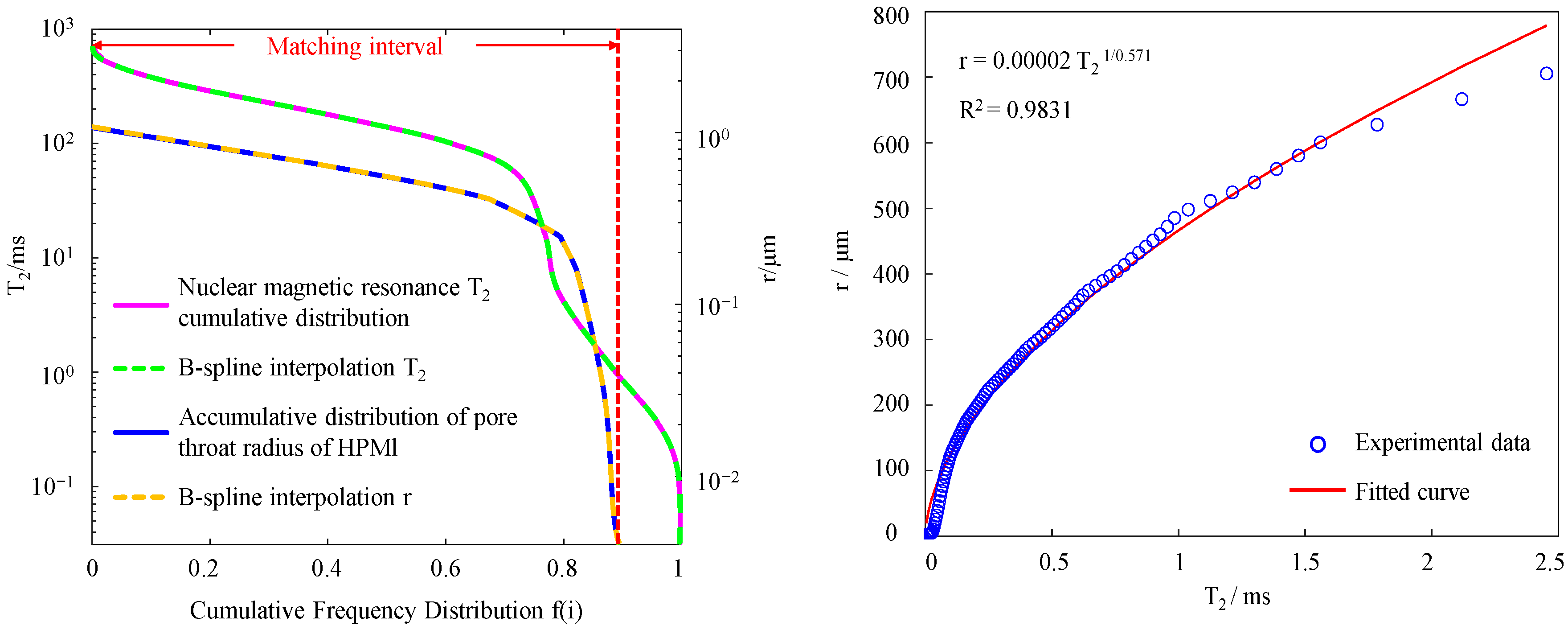
According to Equation (6), the fitting parameters C and n corresponding to different core samples can be obtained by fitting the T2–pore–throat radius relationship. Thus, the transverse relaxation time (T2) distribution of different core types can be converted into pore–throat size distribution curves, thereby enabling a quantitative characterization of the microscopic heterogeneity of pore structures in low-permeability carbonate reservoirs. The specific conversion procedure is described as follows. The NMR T2 distribution data of core samples under oil-saturated or water-saturated conditions are accumulated to obtain the cumulative frequency distribution of T2, which is constructed from large to small relaxation times. A matching relationship is then established between the cumulative T2 distribution and the pore–throat radius distribution obtained from MICP experiments. A dual-axis plot is constructed using the cumulative frequency as the horizontal axis with the relaxation time T2 and pore–throat radius as the vertical axes.
Considering that MICP measurements cannot fully capture the complete pore–throat structure, only the portion of the T2 cumulative frequency distribution corresponding to f(i) < fHg,max is selected for comparison with the cumulative pore–throat radius curve obtained from MICP (as shown in Figure 3). This ensures a one-to-one correspondence between T2 and the pore–throat radius r, thereby guaranteeing the reliability of the conversion results.

5. Results and Discussion

5.1. Heterogeneous Characteristics of Pore–Throat Structure in Carbonate Rocks

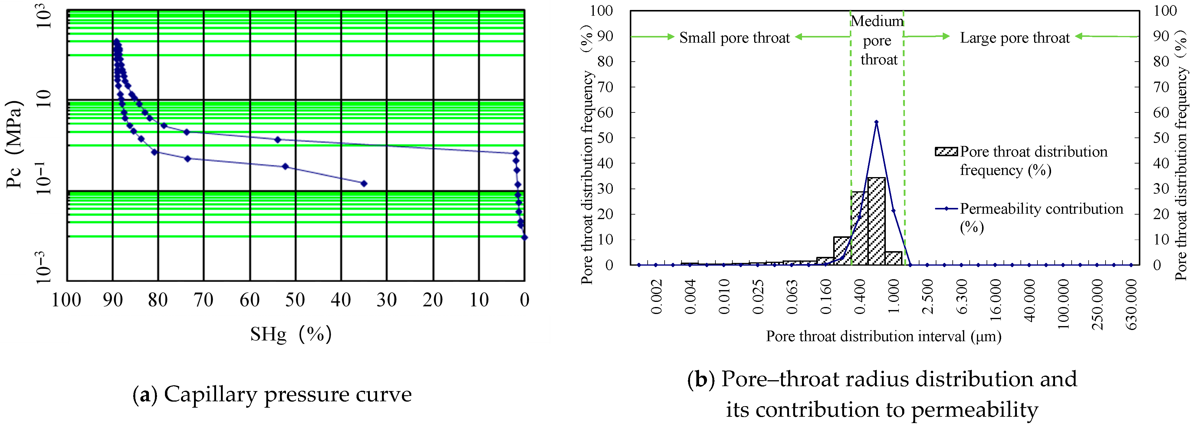
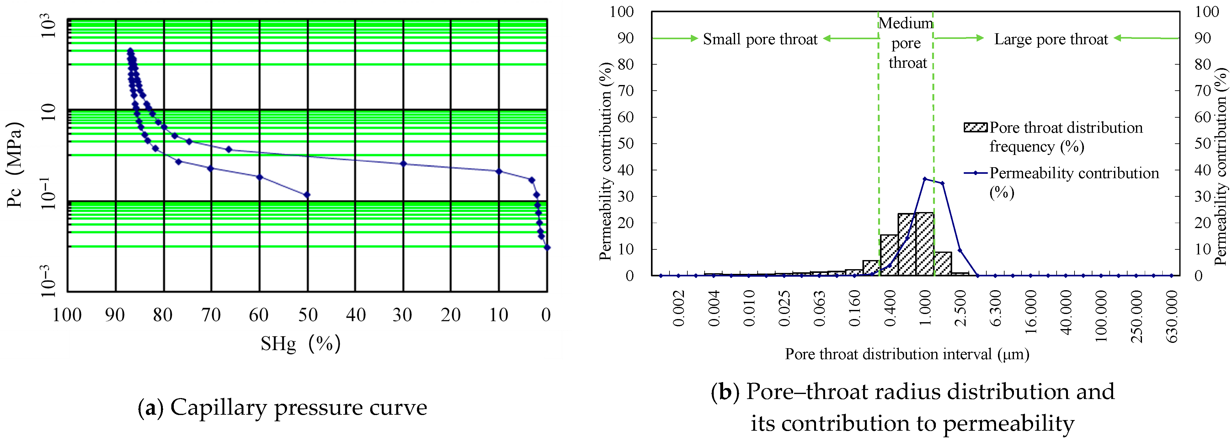
Figure 4 shows the pore–throat structure distribution characteristics and the corresponding MICP curve of the representative core (Core 1) of RT3-type rock. The capillary pressure curve is relatively gentle overall with a comparatively high displacement pressure averaging 0.67 MPa and a median saturation pressure of 1.30 MPa. The maximum mercury intrusion saturation of Core 1 reaches 89.23%, and the mercury ejection efficiency is 60.75%. The pore–throat size distribution is relatively concentrated and is dominated by medium-sized pore–throats, exhibiting a unimodal pattern with a single prominent peak. The maximum, average, and median pore–throat radii are 1.097 μm, 0.297 μm, and 0.567 μm, respectively. The sorting coefficient is 1.145, indicating a good sorting of pore–throat sizes, while the skewness of 0.204 suggests a slight bias toward the medium pore–throat range, reflecting relatively weak microscopic heterogeneity.
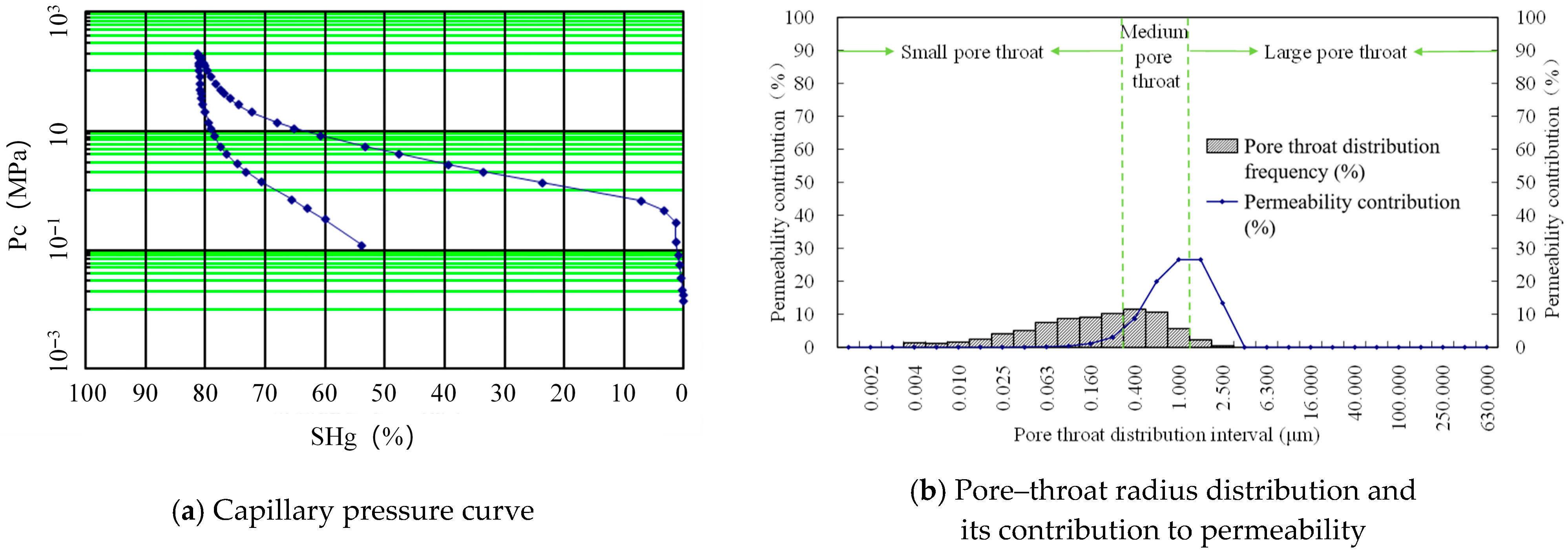
Figure 5 presents the pore–throat structure distribution and MICP curve of the representative core (Core 2) of RT4-type rock. Compared with RT3-type rock, the capillary pressure curve shifts to a lower level with a reduced displacement pressure averaging 0.29 MPa and a median saturation pressure of 1.03 MPa. The maximum mercury intrusion saturation and mercury ejection efficiency are 86.97% and 42.32%, respectively, which are both lower than those of RT3-type rock. The maximum, average, and median pore–throat radii are 2.534 μm, 0.698 μm, and 0.712 μm, respectively, indicating that both medium and large pore–throat structures are well developed and that the distribution range is significantly broadened. The pore–throat radius distribution exhibits bimodal to multimodal characteristics, reflecting the coexistence of pore–throats of different scales and a pronounced increase in microscopic heterogeneity.
Figure 6 shows the pore–throat structure distribution and MICP curve of the representative core (Core 3) of RT5-type rock. The displacement pressure remains low at approximately 0.29 MPa with a median saturation pressure of 1.03 MPa. The maximum mercury intrusion saturation (81.21%) and mercury ejection efficiency (33.67%) are the lowest among the three rock types. The pore–throat size distribution is highly heterogeneous. The maximum, average, and median pore–throat radii are 2.518 μm, 0.384 μm, and 0.158 μm, respectively, indicating that small and medium pore–throat structures dominate with locally developed larger pore–throat structures. The distribution exhibits clear multi-scale characteristics, generally presenting a complex multimodal pattern with a weak primary peak superimposed by multiple secondary peaks. The average sorting coefficient reaches 3.314, indicating the poorest sorting and the strongest heterogeneity among the three rock types.
According to the overall distribution patterns of pore–throat radii in different types of low-permeability carbonate rocks, significant differences are observed in both the distribution frequency and permeability contribution of pore–throat structures across different size ranges. To further quantitatively evaluate the mobility of crude oil hosted in pore–throat structures of different sizes, pore–throat classification was performed based on the pore–throat distribution frequency and permeability contribution characteristics obtained from the combined MICP–NMR analysis, as shown in Figure 4b, Figure 5b and Figure 6b. Pore–throat structures smaller than 0.3 μm are classified as fine pore–throat structures, those between 0.3 μm and 1.5 μm are classified as medium pore–throat structures, and those larger than 1.5 μm are classified as large pore–throat structures. This classification criterion effectively captures the development characteristics and flow capacity differences of pore–throat structures at different scales in the reservoir.

5.2. Crude Oil Production Characteristics During Water-Alternating-CO2 Miscible Flooding

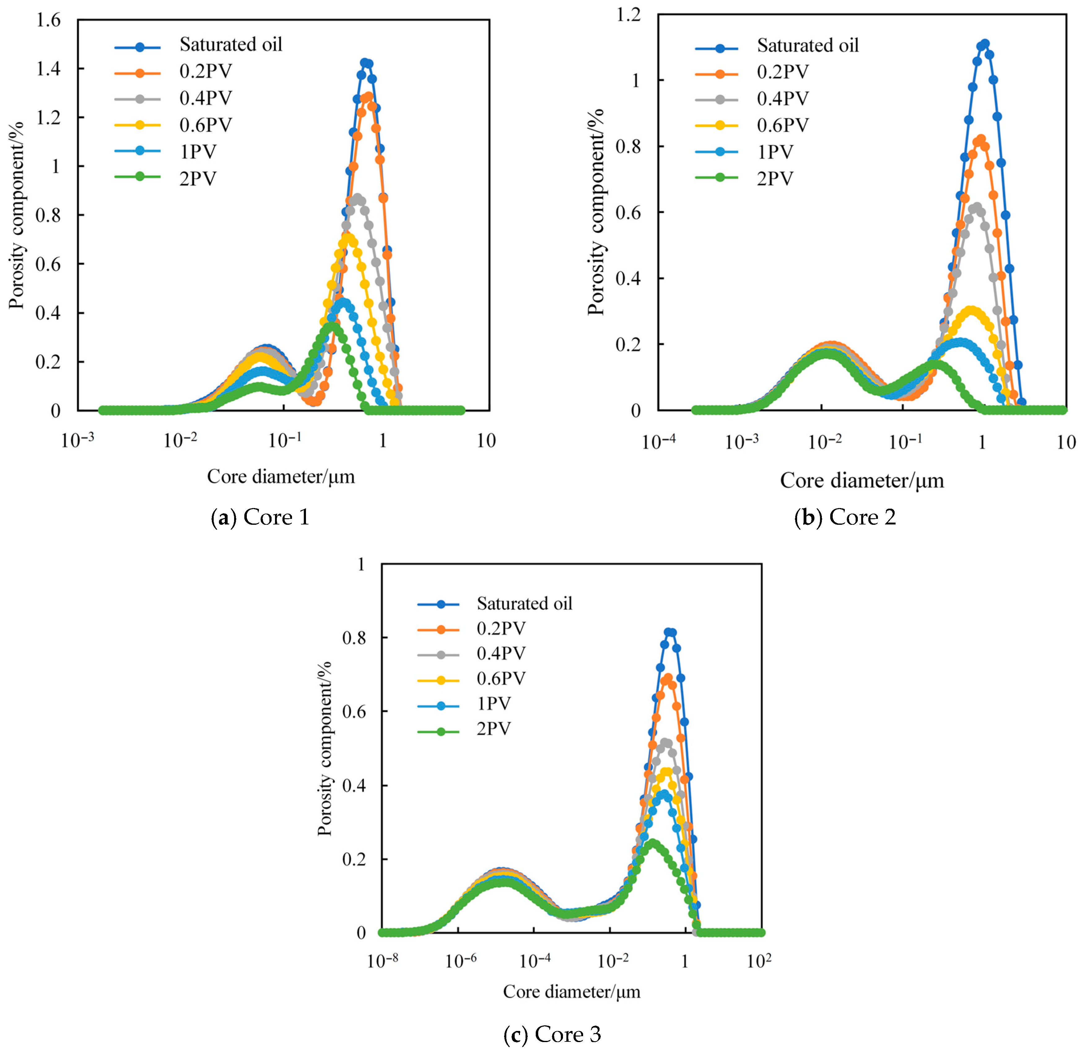
Figure 7 shows the NMR T2 spectrum distribution curves of different rock types during water-alternating-CO2 miscible flooding, which systematically reflect the microscopic production process and evolution of crude oil within pore–throat spaces. Before flooding, the NMR signals of all cores are mainly concentrated in the medium–large pore–throat regions with good connectivity, indicating that crude oil preferentially resides in medium–large pore–throat structures. With the progress of water-alternating-CO2 miscible flooding, the injected CO2 slugs gradually dissolve into the crude oil, leading to reductions in viscosity and interfacial tension. Meanwhile, the observed improvement in microscopic sweep efficiency is considered to be consistent with Jamin-type flow resistance effects induced by gas–water alternating slugs. These effects result in significant changes in both the amplitude and distribution of the transverse relaxation time (T2) signals. At the early stage of flooding, the NMR signals corresponding to medium–large pore–throat structures in all cores decrease markedly, indicating that these regions are the primary zones for crude oil production during alternating miscible flooding.
The heterogeneity of rock pore–throat structures exerts a significant control on crude oil production characteristics. For Core 1, which exhibits a relatively uniform pore–throat distribution and low seepage resistance, the NMR signals corresponding to pore–throat structures of different scales decrease substantially during flooding, indicating rapid crude oil production and high displacement efficiency. In contrast, for Cores 2 and 3, crude oil hosted in medium–large pore–throat structures is preferentially produced, whereas the production of crude oil in fine pore–throat structures remains limited, suggesting that the injected CO2 is insufficient to overcome the strong capillary resistance in fine pore–throat structures.
Further analysis shows that crude oil in medium–large pore–throat structures of Core 2 is almost completely produced, whereas a considerable amount of remaining oil still exists in medium–large pore–throat structures of Core 3 at the end of flooding. This indicates that the microscopic heterogeneity of pore–throat structures plays a key role in controlling the effectiveness of water-alternating-CO2 miscible flooding in marine carbonate reservoirs.
In addition, the injected supercritical CO2 can dissolve in formation water to generate carbonic acid, which may alter mineral surfaces and weaken the cementation strength of rock particles [41]. Under such conditions, particle detachment, mineral dissolution, and deposition phenomena may occur and locally modify pore–throat connectivity and flow behavior during CO2 flooding [42]. Meanwhile, gas fingering and preferential flow behavior may further intensify the heterogeneity of microscopic displacement fronts during CO2 flooding [43]. These combined effects may contribute to the leftward shift of the NMR distribution peak toward the fine pore–throat region observed during the flooding process.

5.3. Evaluation of Crude Oil Mobility in Pore–Throat Structures of Different Scales

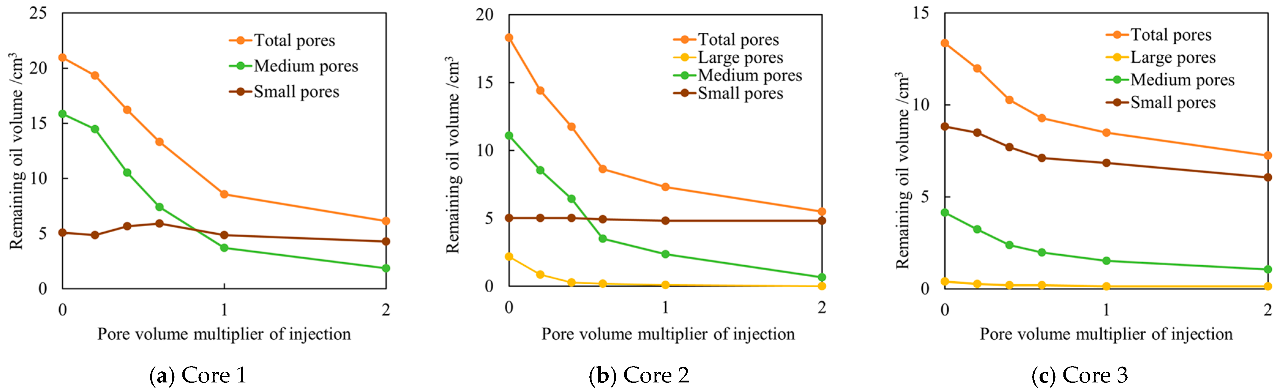
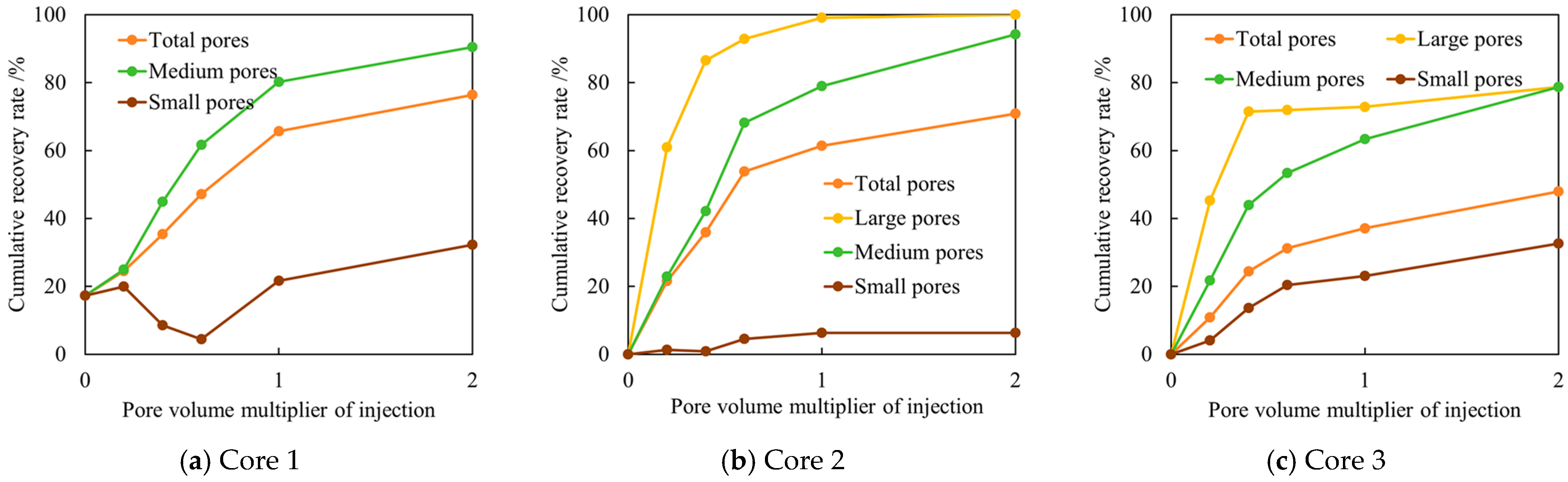
Based on the pore–throat classification in Section 5.1 and the T2–pore radius conversion relationship established in Section 4, the corresponding T2 intervals for different pore–throat classes were identified for each core type. Accordingly, the variation curves of the remaining oil volume and crude oil recovery degree for the whole core (“Total pores”) and different pore–throat size intervals were quantitatively evaluated, as shown in Figure 8 and Figure 9. Overall, all three cores exhibit pronounced staged oil displacement characteristics during water-alternating-CO2 miscible flooding: crude oil in large pore–throat structures is displaced preferentially, medium pore–throat structures serve as the primary contribution space for oil recovery, whereas oil displacement in fine pore–throat structures is relatively delayed. Notable differences in displacement efficiency are observed among the three cores. From the evolution of remaining oil volume, at the initial flooding stage (PV < 0.5), the oil volume in large pore–throat structures decreases rapidly, indicating that the flooding front preferentially advances along dominant seepage pathways. Crude oil in medium pore–throat structures is continuously produced and acts as the main region for oil displacement, whereas the oil volume in fine pore–throat structures shows only a slight decline. As the injected PV further increases, the variation in remaining oil volume across different pore–throat scales gradually stabilizes, which is accompanied by a marked reduction in displacement efficiency. A clear negative correlation is observed between pore structure heterogeneity and displacement efficiency during water-alternating-CO2 miscible flooding. For Core 1, the recovery degree of crude oil in medium pore–throat structures reaches 89%, contributing 93.7% to the total recovery, while the contribution from fine pore–throat structures remains limited. Core 2 exhibits favorable multi-scale collaborative oil displacement behavior with crude oil in large pore–throat structures being almost completely displaced and the recovery degree in medium pore–throat structures reaching 94.2%, contributing 80.6% to the total recovery. In contrast, for Core 3, the recovery degree of crude oil in small and medium pore–throat structures is only 32.1% with a contribution rate of 45.0% to the total recovery. Although medium pore–throat structures still represent the main displacement space, with a contribution rate of 50.9%, the overall displacement efficiency is significantly lower than that of the other two cores. From the overall flooding performance, the oil displacement degree in pore–throat spaces is strongly controlled by the distribution characteristics of pore–throat structures. Crude oil in medium-to-large pore–throat structures is more readily and continuously mobilized during water-alternating-CO2 miscible flooding, whereas crude oil in fine pore–throat structures is constrained by capillary forces and exhibits a relatively low displacement degree. This scale-dependent mobilization behavior constitutes a key factor limiting further improvement in recovery efficiency.

5.4. Evolution of the Displacement Front During Water-Alternating-CO2 Miscible Flooding

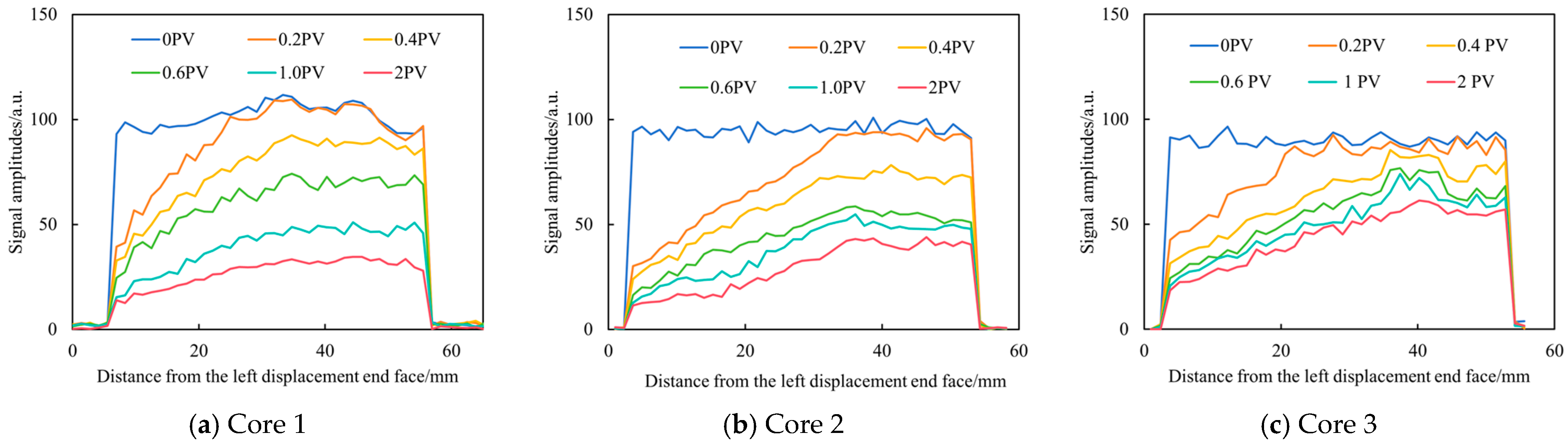
One-dimensional frequency encoding was applied during water-alternating-CO2 miscible flooding using NMR measurements, which directly revealed the spatial distribution of transverse relaxation signal amplitudes along the core (0 mm representing the gas/water injection end). This approach enabled a quantitative characterization of the propagation behavior and dynamic evolution of the displacement front, as illustrated in Figure 10. At a low injected pore volume (0.2 PV), supercritical CO2 rapidly extracted light hydrocarbon components and achieved local miscibility, resulting in a sharp reduction in signal amplitude near the inlet. At this stage, the displacement front had not yet propagated to the outlet end, and thus no significant signal variation was observed in that region. With further injection beyond 0.2 PV, the displacement front exhibited non-uniform advancement due to the inherent heterogeneity of the pore–throat structure. The aqueous phase preferentially broke through along dominant flow pathways, leading to the formation of preferential channels. In the later stage of flooding, the signal amplitude of Core 1 decreased gradually and uniformly along the core, indicating that gas–water alternating injection effectively suppressed gas channeling and improved mobility control. In contrast, for Core 2, the signal amplitude declined more rapidly, reflecting the stronger influence of pore structure heterogeneity on flow redistribution. For Core 3, the spatial disparity of the signal became increasingly pronounced, with dominant seepage pathways controlling the main flow, while low-permeability regions evolved into typical bypassed oil zones.
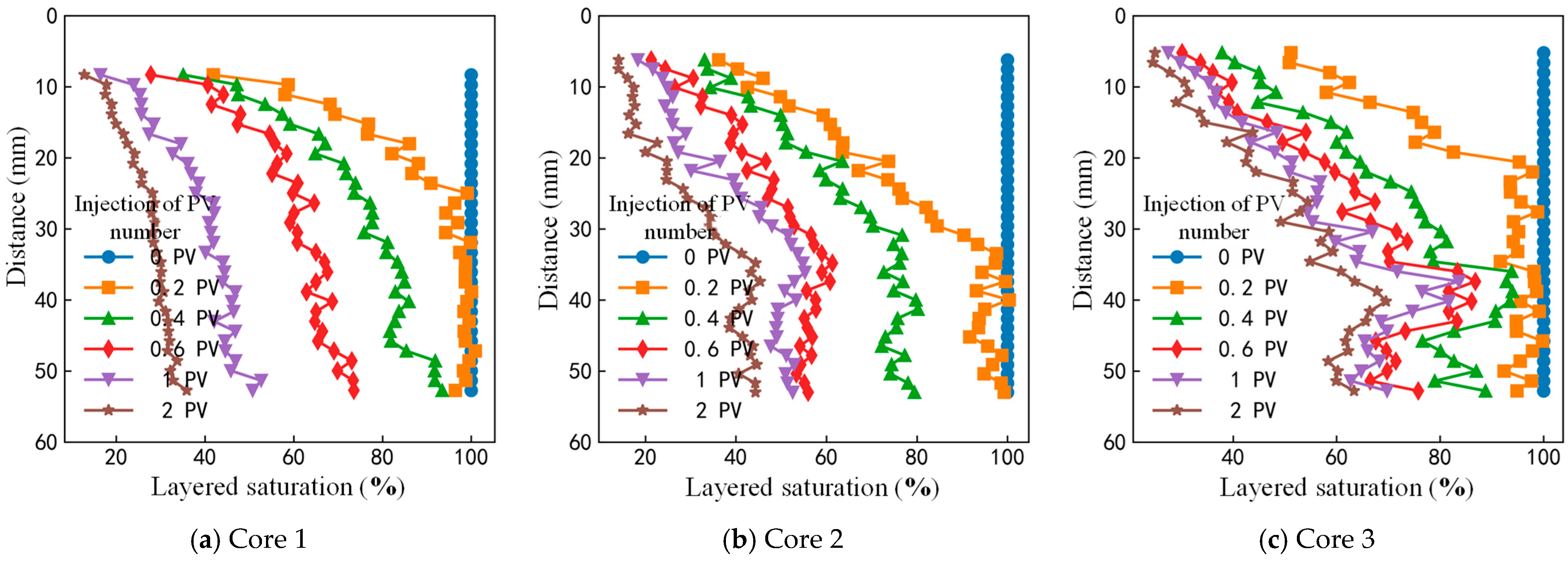
Figure 11 presents the layered saturation distribution in different rock types during water-alternating-CO2 miscible flooding. The variation in interlayer saturation is closely associated with vertical pore–throat heterogeneity, which governs the uniformity of layered saturation distribution at different positions after breakthrough. For Core 3, which exhibits pronounced microscopic heterogeneity, significant differences in layered saturation are observed in the later stage of water-alternating-CO2 miscible flooding. At 0.2 PV, the injected water has already established a preferential flow pathway along the bottom layer, while the gas–water alternating slugs provide only a limited blocking effect. Subsequently, the injected fluids continue to channel rapidly along pathways with low flow resistance, making it difficult to effectively sweep the surrounding low-permeability regions. Moreover, due to the abundance of fine pore–throat structures in Core 3, local pore–throat heterogeneity and wettability differences give rise to capillary barriers. Fine pore–throat structures are most developed in the 35–45 mm region, corresponding to relatively high layered saturation. During the migration of remaining oil within different regions of the core, coalescence occurs, forming clustered remaining oil that migrates collectively toward the outlet end. As a result, higher oil saturation is observed near the outlet. As dissolution effects progressively enlarge the flow pathways, the signal at the outlet end gradually decreases in the later stage.
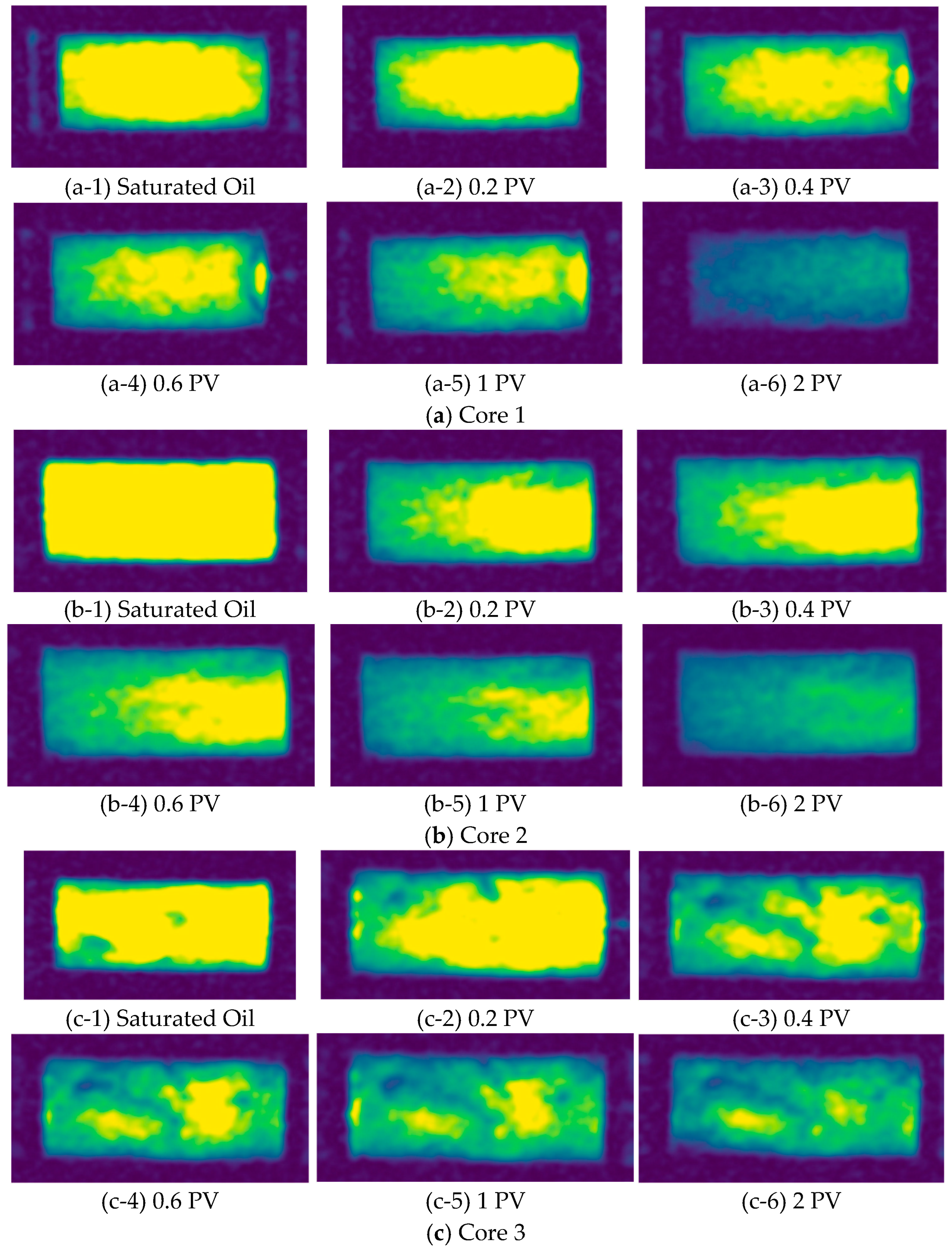
Figure 12 displays NMR imaging results in different types of carbonate rocks during water-alternating-CO2 miscible flooding, where yellow represents oil and green represents the injected medium (deuterated water/CO2). These images intuitively reflect the spatial distribution and evolution of oil content at the core scale (the left end corresponds to the injection end, and the right end corresponds to the production end). The cores are initially fully saturated with oil. In the early stage of water-alternating-CO2 miscible flooding, the gas phase first invades the inlet end of the core, resulting in a decrease in oil saturation near the inlet. No significant changes are observed in the middle and outlet regions at this stage, while oil is continuously produced at the outlet. This stage contributes a substantial proportion of total oil production, and the displacement front gradually becomes evident. Breakthrough occurs at approximately 0.4 PV for all three cores, which is consistent with the NMR T2 spectrum results, where a pronounced signal reduction is observed at the same injection volume. At this stage, CO2 reduces crude oil viscosity and achieves miscibility primarily in larger pores, while water displaces oil in smaller pores through imbibition. The gas–water alternating injection leads to relatively low residual oil saturation in small pores near the periphery. A comparison of NMR images among the three cores shows that displacement in Core 1 is relatively uniform. Core 2 exhibits a small amount of remaining oil near the outlet end, whereas Core 3 demonstrates better displacement in the upper region, but overall, strong heterogeneity results in highly non-uniform displacement and reduced displacement efficiency. CO2 preferentially occupies pores in the upper–middle part of the core, forming a gas-cap-like displacement pattern, while water preferentially migrates downward. Consequently, the lower part of the core evolves into a displacement blind zone with enriched residual oil. Pore structure analysis further indicates that Core 3 possesses strong heterogeneity, which promotes rapid gas channeling along high-permeability layers. This behavior weakens the effectiveness of water-alternating-CO2 cycling and limits incremental oil recovery.

6. Conclusions

High-temperature and high-pressure online NMR measurements were employed to investigate water-alternating-CO2 miscible flooding in low-permeability carbonate rocks. Combined with MICP measurements, a quantitative conversion relationship between the transverse relaxation time T2 and pore–throat radius was established. The oil mobilization mechanisms of water-alternating-CO2 miscible flooding under pore structure heterogeneity were systematically elucidated. The main conclusions are as follows:
(1)
Low-permeability carbonate reservoirs in the Middle East exhibit pronounced multimodal pore–throat distribution characteristics with a weak correlation between porosity and permeability. Significant differences in pore–throat radius distribution, displacement pressure, and flow capacity are observed among different rock types. Strong pore–throat heterogeneity serves as a key geological factor controlling fluid displacement behavior and oil mobilization potential.
(2)
Water-alternating-CO2 miscible flooding lowers the effective utilization threshold of pore–throat structures and enables oil mobilization across multiple pore scales. Oil in large pores is preferentially mobilized, mesopores constitute the primary contribution to oil production, and oil mobilization in small pores remains limited. For representative cores, mesopores contribute the largest proportion to total recovery (93.7%, 80.6%, and 50.9%, respectively), indicating that mesopore-dominated pore–throat structures are the principal targets for oil mobilization.
(3)
Water-alternating-CO2 miscible flooding exhibits distinct stage-wise characteristics. In the early stage (PV < 0.5), alternating injection of CO2 and water effectively suppresses gas channeling, resulting in relatively high displacement efficiency. As injection proceeds (PV > 1.0), the variation in remaining oil volume gradually stabilizes, and displacement efficiency declines, indicating the transition to a low-efficiency circulation stage. Increased pore–throat heterogeneity significantly limits further oil mobilization in the later stage.
(4)
Pore structure heterogeneity exerts a dominant control on recovery performance. Cores with relatively uniform pore–throat distributions (RT3 and RT4) exhibit favorable displacement efficiency. In contrast, RT5-type rocks, characterized by a high proportion of fine pore–throat structures and strong heterogeneity, promote preferential flow and early gas channeling, resulting in a limited mobilization of remaining oil in low-permeability regions and reduced enhanced oil recovery effectiveness.
(5)
The present results also provide useful implications for water-alternating-CO2 miscible flooding development in heterogeneous low-permeability carbonate reservoirs. The strong influence of pore–throat structure heterogeneity on oil mobilization behavior suggests that WAG injection parameters should be optimized according to reservoir pore structure characteristics. In addition, controlling preferential flow and gas channeling remains important for improving sweep efficiency during alternating miscible flooding in highly heterogeneous carbonate reservoirs.

Author Contributions

Conceptualization, J.S.; Methodology, J.S., H.P., Z.H. and J.C.; Investigation, J.S., H.P., Y.Y., Y.Z., Z.H. and J.C.; Resources, H.P. and Y.Y.; Data curation, Y.Y., Y.Z. and Z.H.; Writing—original draft, J.S., H.P., Z.H. and J.C.; Writing—review and editing, J.S. and J.C.; Visualization, H.P., Y.Y., Y.Z. and Z.H.; Supervision, J.C.; Project administration, J.S. and J.C.; Funding acquisition, J.S. and H.P. All authors have read and agreed to the published version of the manuscript.

Funding

This research received no external funding.

Data Availability Statement

The original contributions presented in this paper are included in the article. Further inquiries can be directed to the corresponding author.

Conflicts of Interest

Author Jingjing Sun was employed by the company Sinopec Petroleum Exploration and Production Research Institute, Beijing, China. Author Hui Peng was employed by the company PetroChina Research Institute of Petroleum Exploration and Development, Beijing, China. The remaining authors declare that the research was conducted in the absence of any commercial or financial relationships that could be construed as a potential conflict of interest.

References

  1. Roehl, P.O.; Choquette, P.W. Carbonate Petroleum Reservoirs; Springer Science & Business Media: Berlin/Heidelberg, Germany, 2012. [Google Scholar]
  2. Dale, S. BP Statistical Review of World Energy; BPPlc: London, UK, 2021; pp. 14–16. [Google Scholar]
  3. Li, Y.; Kang, Z.; Xue, Z.; Zheng, S. Theories and practices of carbonate reservoirs development in China. Pet. Explor. Dev. 2018, 45, 712–722. [Google Scholar] [CrossRef]
  4. Li, Z.; Tu, C.; Tu, X. Key technologies of overseas low-permeability carbonate reservoirs. Fault-Block Oil Gas Field 2024, 31, 955–958. [Google Scholar]
  5. Zhu, H.; Zhang, J.; Wu, S.; Zhang, Y. Research on Development Regime by Gas Drive in Low Permeability Reservoir. Unconv. Oil Gas 2014, 1, 43–46. [Google Scholar]
  6. Wang, Y.; Tang, H.; Lu, H.; Yu, W. A study on the pore structure of carbonate rocks and its effect on oil movability in the Kh2 Member of Upper Cretaceous Khasib Formation in X oilfield, Iraq. Geol. Rev. 2020, 66, 1. [Google Scholar]
  7. Song, X.; Li, Y. Optimum development options and strategies for water injection development of carbonate reservoirs in the Middle East. Pet. Explor. Dev. 2018, 45, 723–734. [Google Scholar] [CrossRef]
  8. Yu, Y.; Guo, R.; Lin, R.; Shen, Y.; Shen, B.; Zhu, G.; Li, F.; Wang, Y.; Yan, Y. Pore throat structure characteristics and development countermeasures of carbonate reservoirs in the Middle East: A case study of M Formation in X oilfield in Iraq. Acta Pet. Sin. 2023, 44, 369–384. [Google Scholar]
  9. Li, M.; Liao, X.; Li, Q.; Lu, N.; Su, Z. Optimization of CO2 immiscible injection in complex low permeability reservoir. J. Shaanxi Univ. Sci. Technol. 2017, 35, 98–102. [Google Scholar]
  10. Carpenter, C. Experimental Program investigates miscible CO2 WAG injection incarbonate reservoirs. J. Pet. Technol. 2019, 71, 47–49. [Google Scholar] [CrossRef]
  11. Li, M.; Guan, H.; Hu, S.; Wang, X.; Li, Q.; Yuan, S. Optimization of water gas alternate injection production parameters for miscible and immiscible CO2 flooding in ultra-low permeability reservoir. Unconv. Oil Gas 2021, 8, 60–66. [Google Scholar]
  12. Wang, J.; Gao, Y.; Zong, C.; Zhao, M.; Chen, Q. Response characteristics of CO2-immiscible-flooding WAG in the ultra-low permeability oil reservoirs. Pet. Geol. Oilfield Dev. Daqing 2016, 35, 116–120. [Google Scholar]
  13. Li, J.; Duan, J.; Yao, Z.; Li, N.; Chen, F.; Zha, Y.; Zhao, Y. Analysis on Influence Factors of Enhanced Oil Recovery in CO2 Flooding After Water Flooding in Low Permeability Reservoir. Unconv. Oil Gas 2017, 4, 45–52. [Google Scholar]
  14. Lashkarbolooki, M.; Ayatollahi, S. Experimental investigation on CO2-light crude oil interfacial and swelling behavior. Chin. J. Chem. Eng. 2018, 26, 373–379. [Google Scholar] [CrossRef]
  15. Sun, H.; Zhu, Y.; Wei, Y.; Gao, Y. Influence mechanism of acidification on oil recovery during CO2 flooding. Lithol. Reserv. 2020, 32, 136–142. [Google Scholar]
  16. Li, Z.; Su, Y.; Li, L.; Hao, Y.; Wang, W.; Meng, Y.; Zhao, A. Evaluation of CO2 storage of water alternating gas flooding using experimental and numerical simulation methods. Fuel 2022, 311, 122489. [Google Scholar] [CrossRef]
  17. Pancholi, S.; Negi, G.S.; Agarwal, J.R.; Bera, A.; Shah, N. Experimental and simulation studies for optimization of water–alternating-gas (CO2) flooding for enhanced oil recovery-Science Direct. Pet. Res. 2020, 5, 227–234. [Google Scholar] [CrossRef]
  18. Luo, X.; Zheng, P.; Gao, K.; Wei, B.; Feng, Y. Thermo- and CO2-triggered viscosifying of aqueous copolymer solutions for gas channeling control during water-alternating-CO2 flooding. Fuel 2021, 291, 120171. [Google Scholar] [CrossRef]
  19. Song, X.; Wang, F.; Ma, D.; Gao, M.; Zhang, Y. Progress and prospect of carbon dioxide capture, utilization and storage in CNPC oilfields. Pet. Explor. Dev. 2023, 50, 206–218. [Google Scholar] [CrossRef]
  20. Chen, H.; Liu, X.; Zhang, C.; Tan, X.; Yang, R.; Yang, S.; Yang, J. Effects of miscible degree and pore scale on seepage characteristics of unconventional reservoirs fluids due to supercritical CO2 injection. Energy 2022, 239, 122287. [Google Scholar] [CrossRef]
  21. Ji, B.; He, Y. Practice and understanding about CO2 flooding in low permeability oil reservoirs by Sinopec. Pet. Reserv. Eval. Dev. 2021, 11, 805–844. [Google Scholar]
  22. Lee, S.; Lo, H.; Dharmawardhana, B. Analysis of mass transfer mechanisms occurring in rich gas displacement process. In Proceedings of the SPE Annual Technical Conference and Exhibition, Houston, TX, USA, 2–5 October 1988. SPE-18062-MS. [Google Scholar]
  23. Zhou, Y.; Wang, R.; Gou, F.; Lang, D. CO2 flooding mechanism in high water cut reservoirs. Acta Pet. Sin. 2016, 37, 143. [Google Scholar]
  24. Le Van, S.; Chon, B.H. Effects of Salinity and Slug Size in Miscible CO2 Water-Alternating-Gas Core Flooding Experiments. J. Ind. Eng. Chem. 2017, 52, 99–107. [Google Scholar] [CrossRef]
  25. He, Y.; Qiu, S.; Qin, J.; Tang, Y.; Yu, W.; Wang, Y.; Du, X.; Rui, Z. Feasibility of CO2-water alternate flooding and CO2 storage in tight oil reservoirs with complex fracture networks based on embedded discrete fracture model. Energy 2025, 319, 135065. [Google Scholar] [CrossRef]
  26. Li, N.; Tan, X.; Yang, R.; Zhang, L.; Wu, J.; Liu, S.; Liu, Y.; Li, L. Mobilization mechanisms and enhanced oil recovery of hydrocarbon gas injection in offshore low-permeability reservoirs after water flooding based on LBM. China Offshore Oil Gas 2024, 36, 80–91. [Google Scholar]
  27. Wang, H.; Zhao, H. Study on the mechanism of minimum-miscible pressure reduction by ultrasonic assisted CO2 flooding. J. Yan’an Univ. (Nat. Sci. Ed.) 2025, 44, 1–7. [Google Scholar]
  28. Yu, H.; Fu, W.; Zhang, Y.; Lu, X.; Cheng, S.; Xie, Q.; Qu, X.; Yang, W.; Lu, J. Experimental study on EOR performance of CO2-based flooding methods on tight oil. Fuel 2021, 290, 119988. [Google Scholar] [CrossRef]
  29. Wang, L.; He, Y.; Wang, Q.; Liu, M.; Jin, X. Multiphase flow characteristics and EOR mechanism of immiscible CO2 water-alternating-gas injection after continuous CO2 injection: A micro-scale visual investigation. Fuel 2020, 282, 118689. [Google Scholar] [CrossRef]
  30. Tian, H. Feasibility Study of CO2 WAG Flooding for “Three Low” Reservoir. Unconv. Oil Gas 2020, 7, 96–101. [Google Scholar]
  31. Li, W.; Dong, Z.; Sun, J.; Schechter, D.S. Polymer-alternating-gassimulation—A case study. In Proceedings of the SPE EOR Conference at Oil and Gas West Asia, Muscat, Oman, 31 March–2 April 2014. SPE-169734-MS. [Google Scholar]
  32. Khan, M.Y.; Mandal, A. The impact of permeability heterogeneity on water-alternating-gas displacement in highly stratified heterogeneous reservoirs. J. Pet. Explor. Prod. Technol. 2022, 12, 871–897. [Google Scholar] [CrossRef]
  33. Zhang, Y.; Yang, Z.; Huang, Y.; Li, H.; Hou, H.; Zhu, G. Study on Reservoir Characteristics and Remaining Oil Distribution of Low Permeability Pore Type Carbonate Rock. J. Jilin Univ. (Earth Sci. Ed.) 2021, 51, 659–668. [Google Scholar]
  34. Sun, T.; Lin, C.; Wang, L. Microscopic formation mechanisms and distribution patterns of remaining oil in the marine clastic reservoirs of the Carboniferous, Tarim Basin. Oil Gas Geol. 2021, 42, 1334–1343. [Google Scholar]
  35. Xiao, W.; Yang, Y.; Huang, C.; Xie, Q.; Chen, X.; Cao, R.; Zheng, L.; Ren, J. Rock wettability and its influence on crude oil producing characteristics based on NMR technology. Pet. Recover. 2023, 30, 10. [Google Scholar]
  36. Yao, Y.; Liu, D.; Cai, Y.; Li, J. Fine quantitative characterization of coal pores and fissures based on NMR and X-CT. Sci. Sin. 2010, 1598–1607. [Google Scholar]
  37. Xiao, L. Nuclear Magnetic Resonance Imaging Well and Rock Nuclear Magnetic Resonance and Its Application; Science Press: Beijing, China, 1998. [Google Scholar]
  38. Guo, J.; Xie, R.; Xiao, L. Pore-fluid characterizations and microscopic mechanisms of sedimentary rocks with three-dimensional NMR: Tight sandstone as an example. J. Nat. Gas Sci. Eng. 2020, 80, 103392. [Google Scholar] [CrossRef]
  39. Slijkerman, W.F.; Hofman, J.P.; Looyestijn, W.J.; Volokitin, Y. A practical approach to obtain primary drainage capillary pressure curves from NMR core and log data. Petrophysics-SPWLA J. Form. Eval. Reserv. Descr. 2001, 42, 334–343. [Google Scholar]
  40. Wang, F.; Yang, K.; Cai, J. Fractal characterization of tight oil reservoir pore structure using nuclear magnetic resonance and mercury intrusion porosimetry. Fractals 2018, 26, 1840017. [Google Scholar] [CrossRef]
  41. AlAhmad, H.A.; Liu, S.; Alabdrabulrasul, A.; Hoteit, H.; Jia, C. Critical review of subsurface processes governing CO2 leakage mechanisms. Adv. Colloid Interface Sci. 2025, 349, 103770. [Google Scholar] [CrossRef] [PubMed]
  42. Gao, H.; Luo, K.-Q.; Wang, C.; Li, T.; Cheng, Z.-L.; Dou, L.-B.; Zhao, K.; Zhang, N.; Liu, Y.-L. Impact of dissolution and precipitation on pore structure in CO2 sequestration within tight sandstone reservoirs. Pet. Sci. 2025, 22, 868–883. [Google Scholar] [CrossRef]
  43. Li, L.; Jia, C.; Yao, J.; Sepehrnoori, K.; Abushaikha, A.; Liu, Y. An investigation of gas-fingering behavior during CO2 flooding in acid stimulation formations. SPE J. 2024, 29, 3369–3386. [Google Scholar] [CrossRef]
Figure 1. Porosity–permeability cross-plot of the target reservoir.
Energies 19 02401 g001
Figure 2. Experimental setup for online NMR monitoring during water-alternating-CO2 miscible flooding.
Energies 19 02401 g002
Figure 3. Dynamic conversion relationship between NMR transverse relaxation time (T2) and pore–throat radius for a typical core sample.
Energies 19 02401 g003
Figure 4. MICP curve and pore–throat radius distribution of RT3-type rock (Core 1).
Energies 19 02401 g004
Figure 5. MICP curve and pore–throat radius distribution of RT4-type rock (Core 2).
Energies 19 02401 g005
Figure 6. MICP curve and pore–throat radius distribution of RT5-type rock (Core 3).
Energies 19 02401 g006
Figure 7. T2 distribution curves from in situ NMR experiments during water-alternating-CO2 miscible flooding.
Energies 19 02401 g007
Figure 8. Dynamic variation in remaining oil volume in pore–throat structures of different scales during water-alternating-CO2 miscible flooding.
Energies 19 02401 g008
Figure 9. Evolution of crude oil recovery degree in pore–throat structures of different scales during water-alternating-CO2 miscible flooding.
Energies 19 02401 g009
Figure 10. Evolution of the displacement front in different rock types during water-alternating-CO2 miscible flooding.
Energies 19 02401 g010
Figure 11. Layered saturation distribution in different rock types during water-alternating-CO2 miscible flooding.
Energies 19 02401 g011
Figure 12. NMR imaging results in different rock types during water-alternating-CO2 miscible flooding.
Energies 19 02401 g012
Table 1. Parameter ranges defining pore structure types for different rock types.
Rock TypeSedimentary–Diagenetic CharacteristicsPore–Throat RadiusDisplacement Pressure (psi)Porosity (%)Permeability (mD)
RT3Moderate to strong cementation;
Weak to no dissolution
Mesopores to small pores (0.3~1.5 μm)100~100014–261–9
RT4Moderate to weak cementation;
Weak to moderate dissolution
Large pores to mesopores to small pores (0.1~2 μm)100~10007–191–8.5
RT5Strong to moderate cementation;
No dissolution
Small pores to mesopores (0.1~1 μm)>10008–210.01–1
Table 2. Porosity and permeability of core samples.
Core IDRock TypeLength (cm)Diameter (cm)Density (g/cm3)Porosity (%)Permeability
(10−3 μm2)
1RT35.0462.5092.21119.53.96
2RT45.0452.5012.25915.83.65
3RT55.0242.5112.4309.710.54
Table 3. Salinity and ionic composition of the experimental brine.
Cations (mg/L)Anions (mg/L)Total Salinity (mg/L)
Na+K+Mg2+Ca2+ClSO42−HCO3−CO32−
75,673.52854.33731.822,690170,15030518.30.1273,063
Disclaimer/Publisher’s Note: The statements, opinions and data contained in all publications are solely those of the individual author(s) and contributor(s) and not of MDPI and/or the editor(s). MDPI and/or the editor(s) disclaim responsibility for any injury to people or property resulting from any ideas, methods, instructions or products referred to in the content.