Article

Compensation for Rapid Voltage Fluctuations in the Grid Using a Wind Turbine with a Doubly Fed Induction Generator


by
Tomasz Lerch
1 and
Raluca-Elena Necula
2,*
1
Department of Power Electronics and Automation of Energy Transformation Systems, AGH University of Krakow, 30-059 Krakow, Poland
2
Department of Automation and Electrical Engineering, Dunărea de Jos University of Galati, 800146 Galati, Romania
*
Author to whom correspondence should be addressed.
Energies 2026, 19(1), 105; https://doi.org/10.3390/en19010105
Submission received: 11 September 2025 / Revised: 4 December 2025 / Accepted: 23 December 2025 / Published: 24 December 2025

Abstract

The growing share of distributed energy resources in the power system increases the number of power quality issues. The variable nature of their generation contributes to voltage fluctuations. This paper proposes a method for compensating voltage fluctuations utilising reactive power generated by a doubly fed induction generator (DFIG). The proposed method was first evaluated using a simulation model developed in the Matlab Simulink R2025a environment and subsequently validated experimentally under laboratory conditions. The results obtained are highly satisfactory, with the compensation time in laboratory tests not exceeding 500 ms. Since DFIGs are used in approximately 50% of wind power plants and the implementation of the proposed approach does not require additional hardware—only modifications to the generator control software—the method appears highly promising. It offers the possibility of rapid deployment without incurring significant costs.

1. Introduction

In recent years, the conventional model of power systems has undergone significant transformations. In the traditional system, the main source of voltage was synchronous generators operating in large power plants. These generators not only produced active power but also covered the system’s reactive power requirements, thereby stabilising the voltage in the grid [1].
The traditional model has shifted markedly due to the rise in distributed generation, defined by the expanding presence of both small and large wind facilities, along with prosumers—users capable of producing electricity via solar systems or compact wind units [2]. A key characteristic of power output from renewables is its inconsistency and limited predictability, which in turn leads to variations in voltage [3]. With the current degree of grid penetration by such technologies, a major challenge faced by system operators is the alteration—particularly the upward drift—of voltage levels stemming from fluctuations in the power fed into the network by distributed producers [4].
The manner in which large wind turbines in wind farms are connected to the grid varies depending on the type of generator. In the case of wind turbines using a doubly fed induction generator (DFIG), the stator windings are connected directly to the grid, and the rotor is connected via a converter. The rotor side converter’s function is twofold: first, to control the active power given off by the stator to the grid and, second, to control the reactive power [5].
The utilisation of reactive power control by means of excitation of a synchronous machine constitutes an effective method for static compensation. However, it should be noted that the time constant of the excitation circuit of synchronous machines is a few to several seconds [6,7] thus rendering this method unsuitable for compensating for rapid voltage changes. In comparison, the time constant in the DFIG rotor circuit is much smaller [8], which allows one to change the value of processed reactive power, both capacitive and inductive, almost immediately. Reactive power generation is inherently constrained by the current parameters of the induction machine and exhibits a decrease as the processed active power increases [9,10].
The installed capacity of wind power is currently quite significant, with 278 GW in the European Union in 2024 [11].
Therefore, the capacity to produce reactive power, which helps stabilise voltage, is crucial. A notable advantage of DFIGs compared to synchronous machines is their ability to provide inductive reactive power across a broader range. For synchronous generators, producing inductive reactive power requires reducing excitation, which may cause instability and, in extreme situations, lead to desynchronisation—an unacceptable outcome. These restrictions do not affect DFIGs, as they function similarly to asynchronous generators. Consequently, the only limits are the stator and rotor current ratings, which can be properly determined during the design phase. The capacity to supply inductive reactive power is particularly valuable for system operators, since it can mitigate local voltage spikes in grids with substantial distributed generation.
The use of dynamic compensation for voltage fluctuations in energy systems has been demonstrated to be an effective solution. A case in point is dynamic voltage restorers (DVRs), which have been extensively studied in the literature, with a thorough overview of these technologies provided in [12,13]. Even though DVR filters are presently employed in the electricity sector [14,15], these devices require substantial investments, which hinders their widespread adoption. The advantage of the proposed solution is that it uses generators that are already present in the system, eliminating the need for additional installation of new equipment.
The voltage fluctuation mitigation methods described above are effective; however, they do not take advantage of the potential of the DFIG to compensate for rapid voltage variations. In the literature, a number of works [10,16,17,18] can be found that address various aspects of reactive power processed by wind turbine generators, but there is a lack of studies on the prevention of fast and short-term voltage deviations using DFIG. The articles [19,20,21] focus on reactive power control in terms of voltage regulation; however, none of them is dedicated to the effectiveness and response speed of voltage fluctuation compensation. This article focusses primarily on the potential of wind turbine generators as devices which, in addition to energy generation, can also contribute to improving voltage quality in power networks.

2. Compensation for Voltage Changes Using Reactive Power

Controlling reactive power flow to compensate for voltage fluctuations in the network is a widely recognised and applied technique, involving the creation of a voltage drop along the reactive component of the line with the appropriate phase [22,23].
For lines with predominantly inductive characteristics, which is the usual case, voltage drops can be offset by generating capacitive reactive power (i.e., injecting reactive power into the grid) [24,25]. The flow of capacitive reactive current causes a voltage rise across the reactance, increasing the voltage at the terminals. Conversely, a voltage increase in the network can be mitigated by absorbing reactive power (inductive reactive power), producing a voltage drop across the line reactance and thereby lowering the terminal voltage at the converter [26,27].
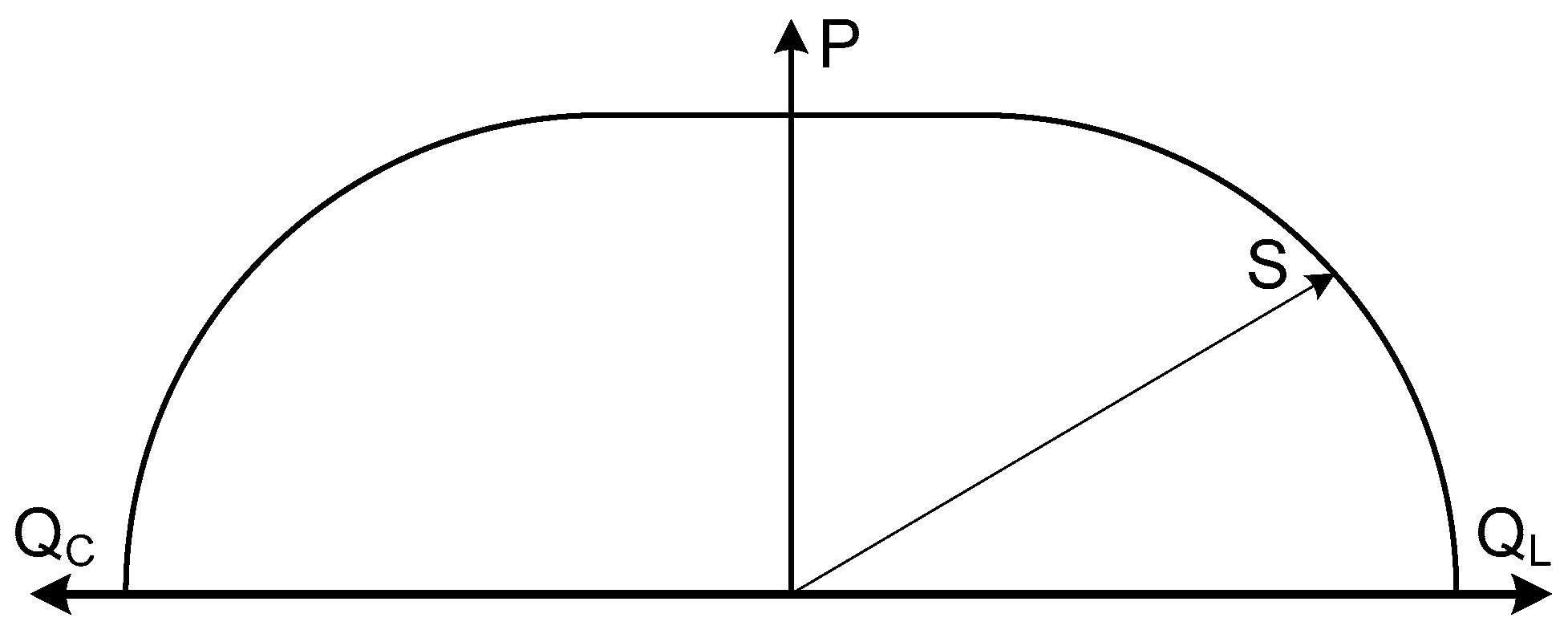
The effectiveness of this voltage fluctuation compensation approach is limited by the current capabilities of the DFIG and is determined by its current operating point [28]. The limitations of reactive power generation can be illustrated in a polar diagram (see Figure 1). As the amount of active power generated increases, the ability to process reactive power decreases because of the stator’s current limitations. However, DFIGs are designed such that the rated apparent power is greater than the rated active power, thereby enabling a certain amount of reactive power to be processed even when the generator reaches its rated active power (see the flat part of the polar diagram).
The solution proposed in this paper aims to prevent rapid voltage fluctuations. This approach distinguishes it from currently applied methods listed, among others, in Section 1. In typical solutions, changing the reactive power setpoint based on demand or voltage variations is performed using a ramp with a defined slope [16,29]. In the proposed solution, the reactive power generated by the DFIG is controlled by a supervisory voltage regulator in such a way that the regulation process is carried out as fast as possible, yet without oscillations or overshoots.

3. Simulation Analysis of the Dynamic Voltage Fluctuation Mitigation System

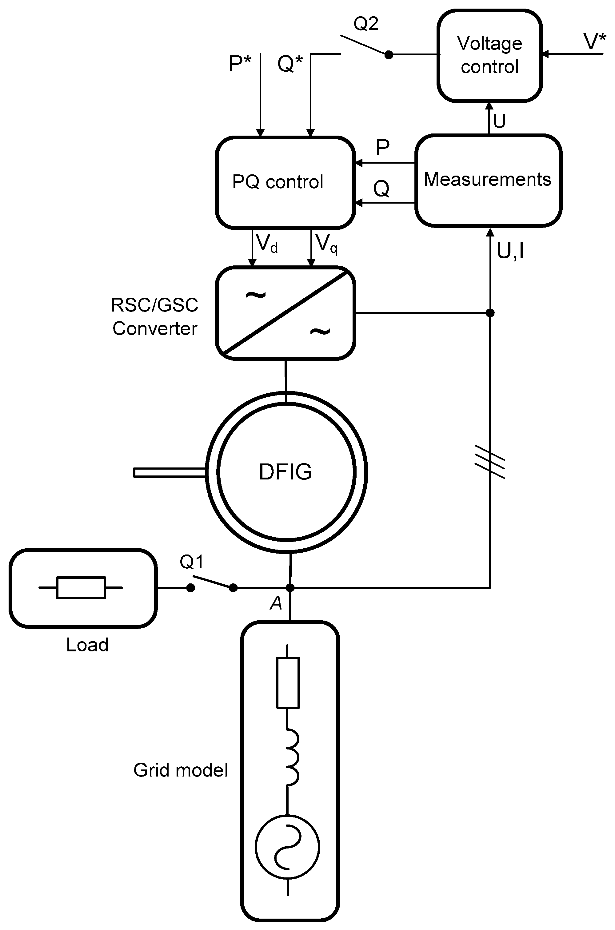
To verify the proposed concept of voltage fluctuation compensation, a dynamic model of a system with a DFIG was developed in the Matlab-Simulink environment. The model includes not only the DFIG with its power control system, but also the network parameters and a parallel-connected load. The voltage control system, which is responsible for maintaining a constant voltage level in the grid, has overarching control over the reactive power processed by the DFIG. A schematic of the simulation model is shown in Figure 2.
In the diagram, the GSC/RSC symbolically represent the Grid-Side Converter (GSC) and the Rotor-Side Converter (RSC). The RSC is responsible for regulating the rotor current to ensure that the DFIG delivers the specified levels of active and reactive power. The primary function of the GSC is to maintain the desired voltage level in the DC link circuit.
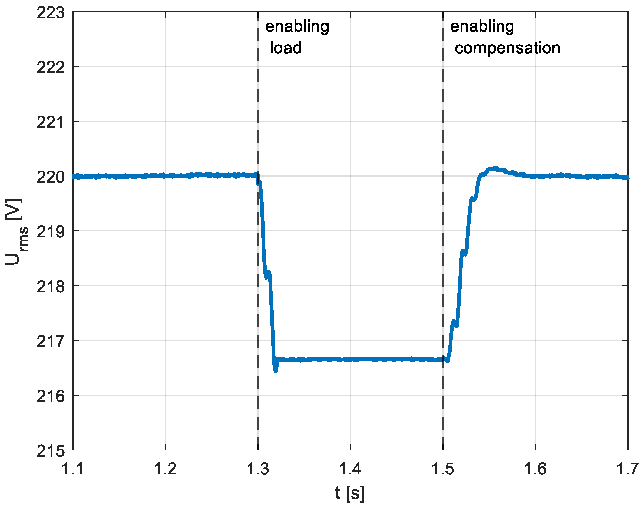
Simulation studies were carried out in two scenarios: the first assumes a voltage drop caused by the connection of a load followed by the activation of the compensation system; the second assumes a voltage drop occurring while the compensation system is already active. The voltage waveform for the first simulation scenario is shown in Figure 3. After the load (switch Q1 in Figure 2), a voltage drop of approximately 3.5 V appears at point enabling load. The depth of the voltage sag at this point depends on the value of the connected load and the impedance of the network. The set values of the active and reactive power (P*, Q*) for the DFIG are zero. After activating the compensation system (switch Q2 in Figure 2), the voltage drop is compensated back to its initial value. As can be seen, the voltage after enabling the compensation system is stable and the regulation time is approximately 50 ms.
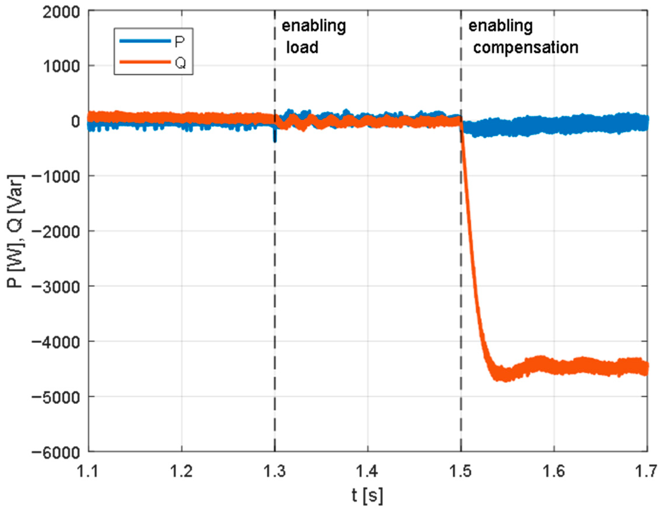
The reactive and active power waveforms processed by the DFIG before and during the operation of the compensation system are shown in Figure 4. Until the compensation system is switched on, both active and reactive power stay at zero, as per the set values. After activation of the compensation system, the reactive power supplied to the grid (of capacitive character) increases to approximately −4.5 kVar. The amount of reactive power that the DFIG must supply to the grid to compensate for the voltage sag depends on the depth of the sag and the network impedance. In the case of a network with a higher impedance, the reactive power required for compensation, according to the principle described in Section 2, will be lower.
The second simulation scenario was carried out using the same load values and network impedance. The difference lies in the switching sequence in the system: the voltage compensation system (switch Q2 in Figure 2) is activated first, followed by the connection of the load (switch Q1 in Figure 2). The voltage waveform is shown in Figure 5. As can be seen, after the compensation system is switched on, the voltage is maintained at the set value. After the load is connected, the momentary voltage sag is compensated in approximately 50 ms. The voltage at point enabling load remains stable during the compensator’s operation, both before and after the sag occurs.
The power waveform shown in Figure 6 is almost identical to the previous scenario, both in terms of dynamics and the steady-state value of the reactive power.

4. Experimental Investigation of the Dynamic Voltage Fluctuation Mitigation System

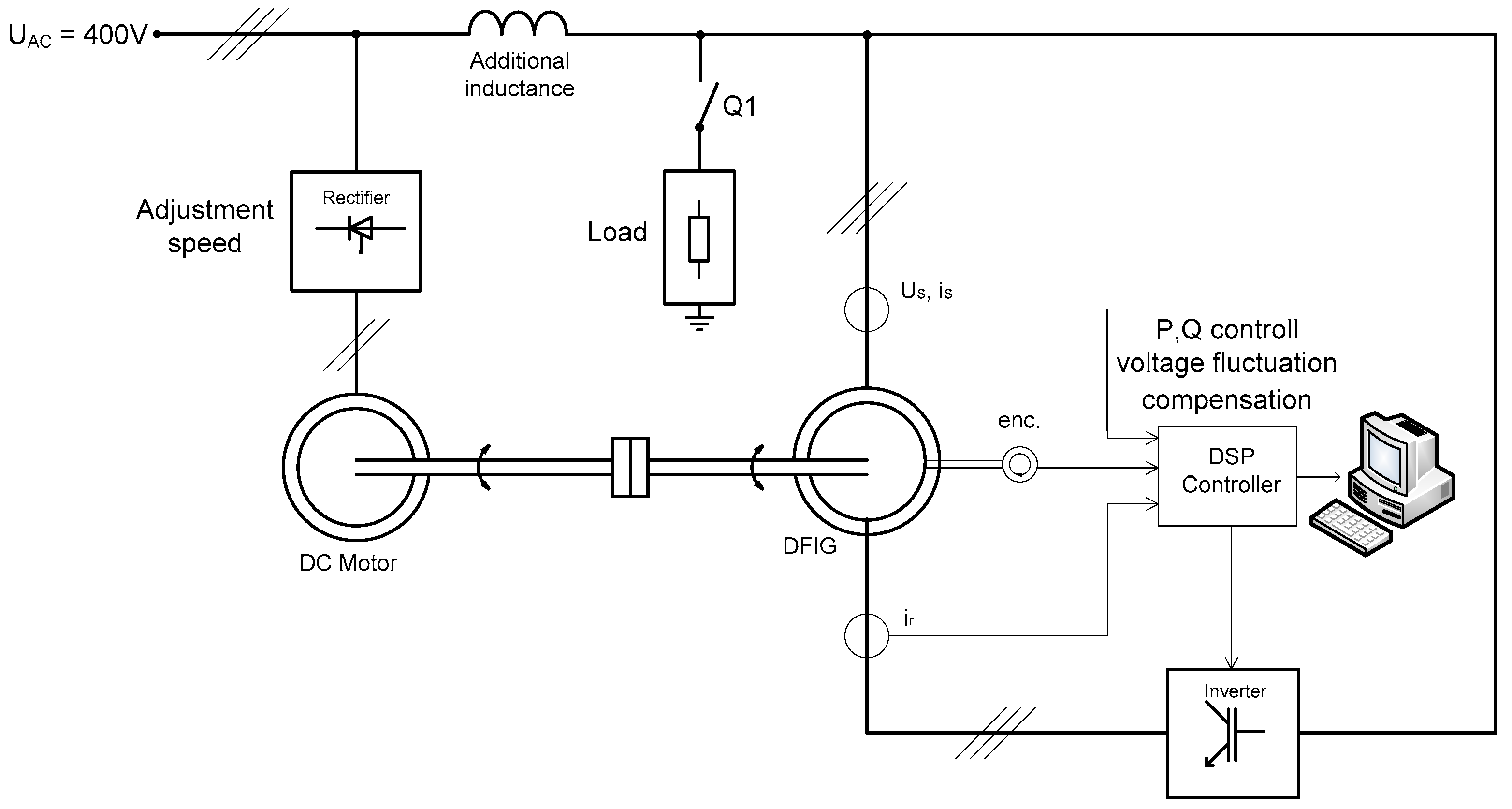
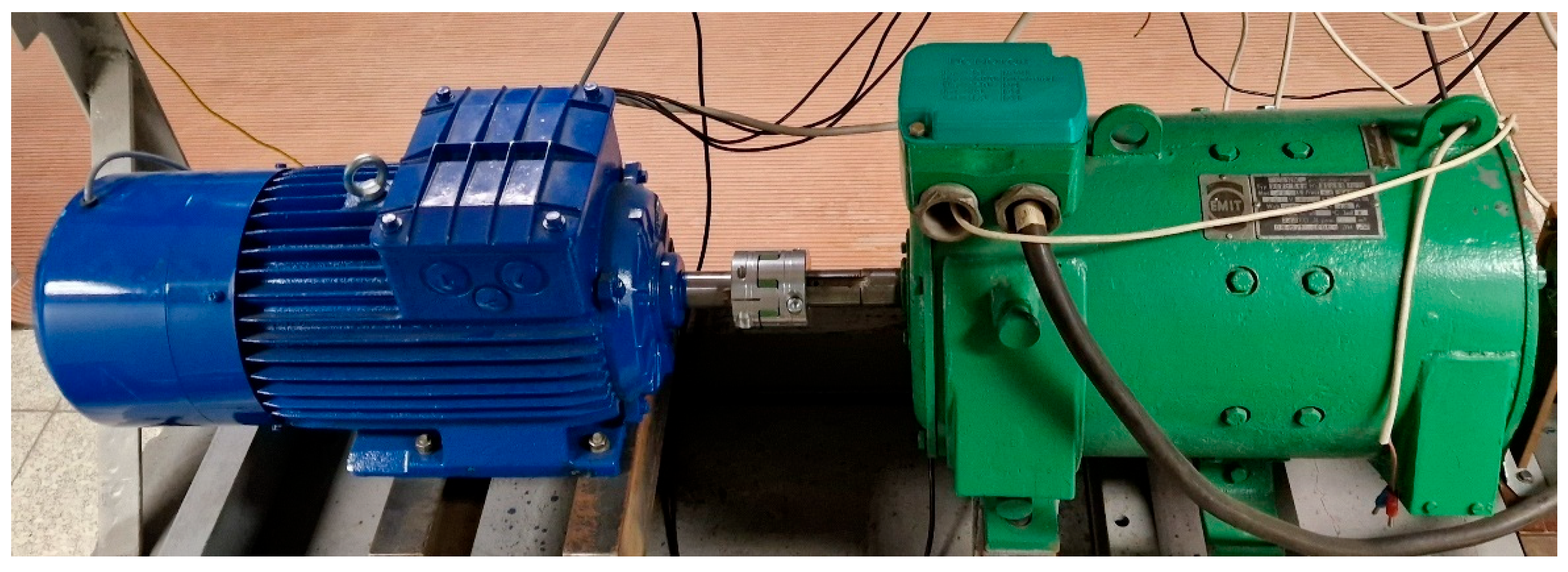
The results of the computer simulations carried out were very promising. However, it should be noted that simulations inherently represent an idealised scenario, often neglecting various aspects of real-world system behaviour. To validate these findings, an experimental study was conducted using a laboratory setup that incorporated a Doubly Fed Induction Generator (DFIG). The schematic diagram of the laboratory system is presented in Figure 7. The main components include a 7.5 kW wound-rotor induction machine and a 10 kW DC drive machine. The complete setup of the machine is shown in Figure 8. In addition, the system, typical for DFIG-based configurations, features a rotor-side converter responsible for controlling the generator operation as well as an auxiliary inductor that emulates grid reactance. The DFIG is controlled via a DSP-based controller that implements an algorithm for both active and reactive power control, along with compensation for voltage fluctuation. The control architecture remains identical to that employed in the simulation environment illustrated in Figure 2.
A load was connected in parallel to the system through circuit breaker Q1. The experiment, similar to the simulation study, involved recording the voltage on the common bus, measured after the additional inductance to which both the load and the DFIG are connected. The experiment was carried out according to the second simulation scenario, in which the DFIG operates with the voltage fluctuation compensation algorithm enabled. Subsequently, the load is connected in parallel to the system.
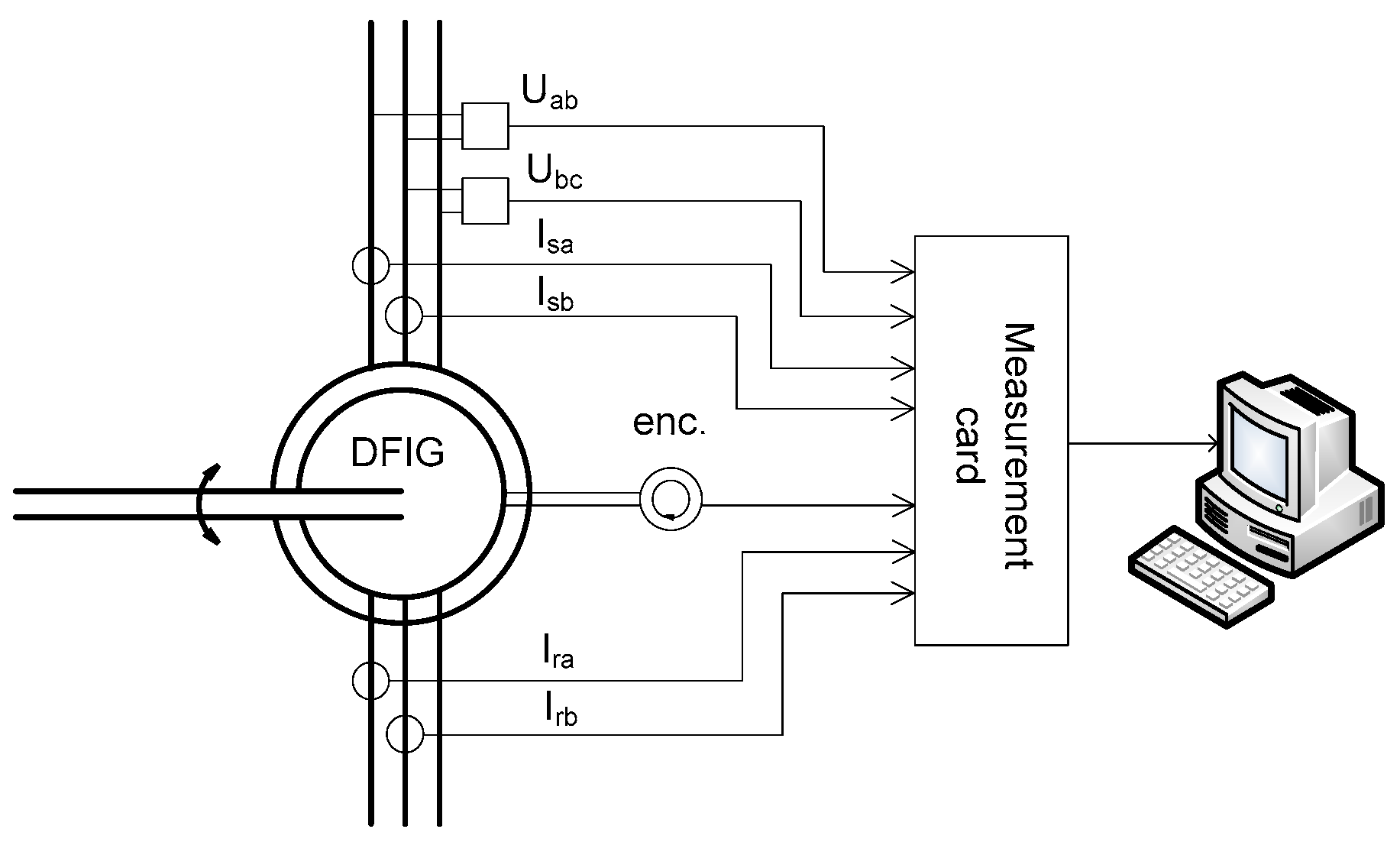
The laboratory measurement system is shown in Figure 9. The setup employs an LEM LV 20-P voltage transducer, an LEM LA 55-P current transducer, and an OMRON E6C2-C incremental encoder. The signals of the individual quantities are acquired using a National Instruments PCI-6221 data acquisition card. The measured quantities are collected by a computer and processed in the LabView environment. The uncertainty of the voltage and current measurements results from both the data acquisition card and the voltage and current transducers. The calculated relative uncertainty was 1.2% for voltage measurement, 0.8% for stator current measurement, and 1% for rotor current measurement.
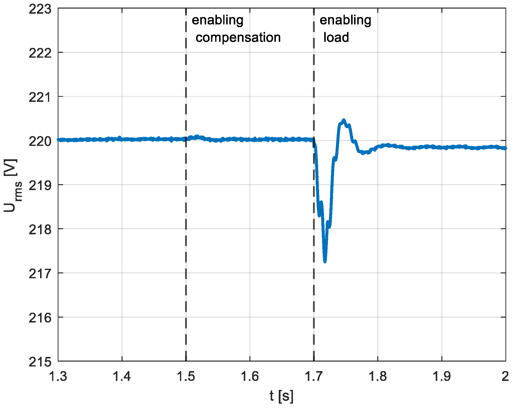
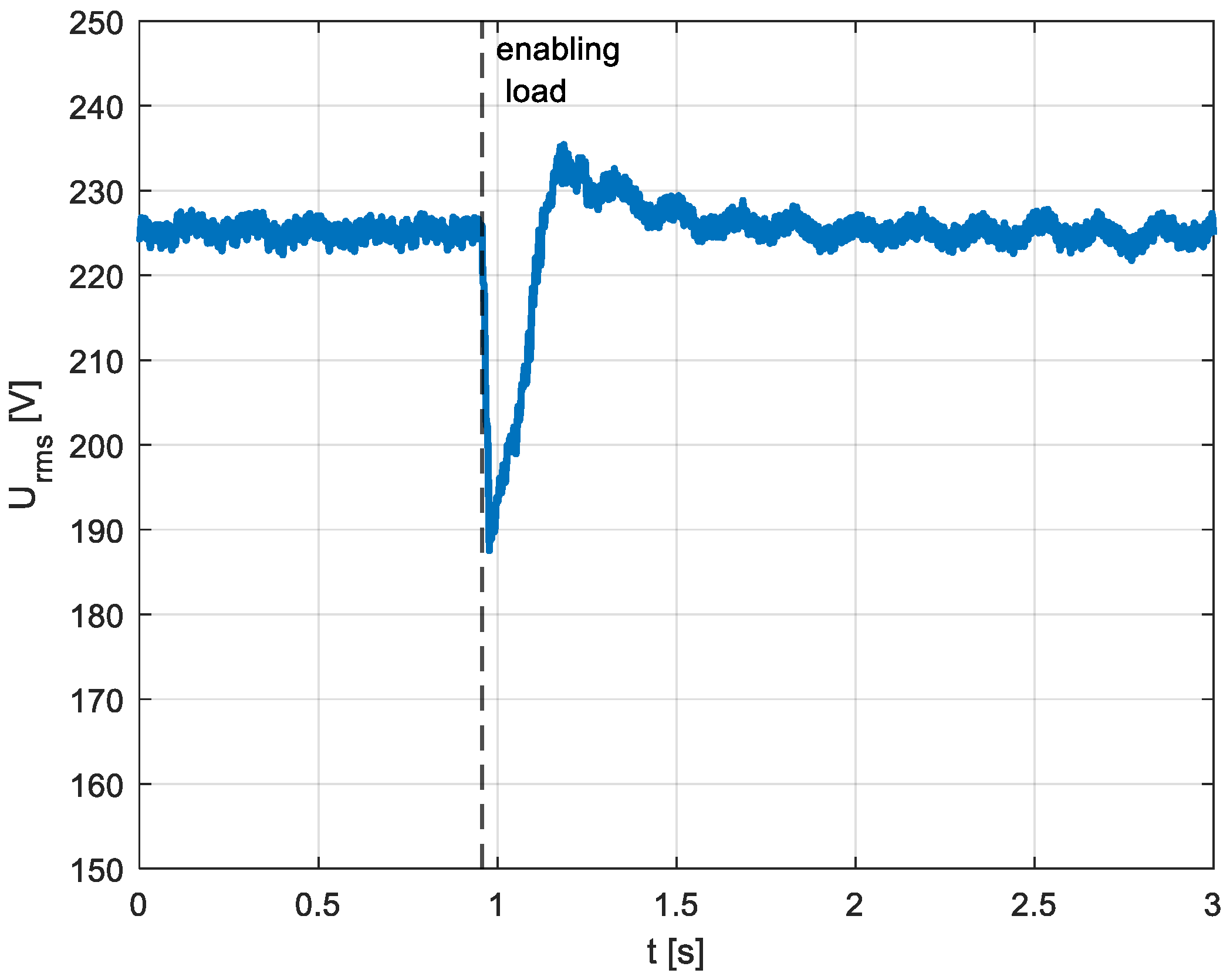
Figure 10 shows the voltage waveform on the common bus after load connection, which occurs at approximately 0.9 s. After the load is switched on, a voltage dip to around 190 V can be observed. This disturbance is compensated for within approximately 0.3 s. The waveform exhibits characteristics similar to the simulation result shown in Figure 5, specifically, the presence of overshoot during the transient response. The primary difference lies in the time required to achieve full compensation. In the experimental setup, this time is noticeably longer due to the dynamic behaviour of various system components, such as the drive and the rotor-side converter, which were not modelled in the simulation studies [30].
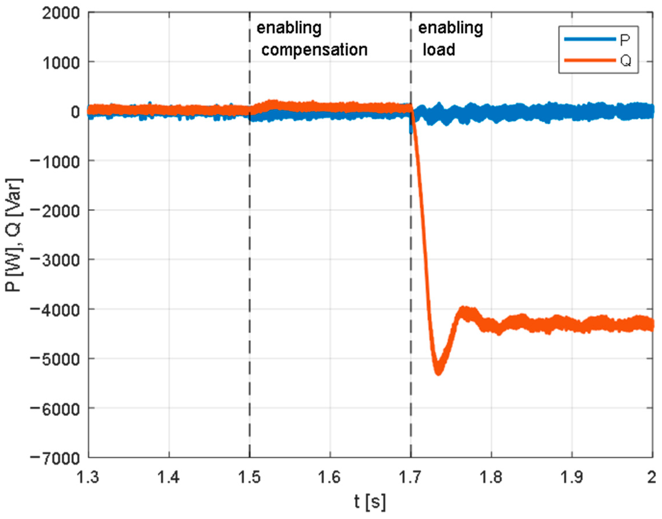
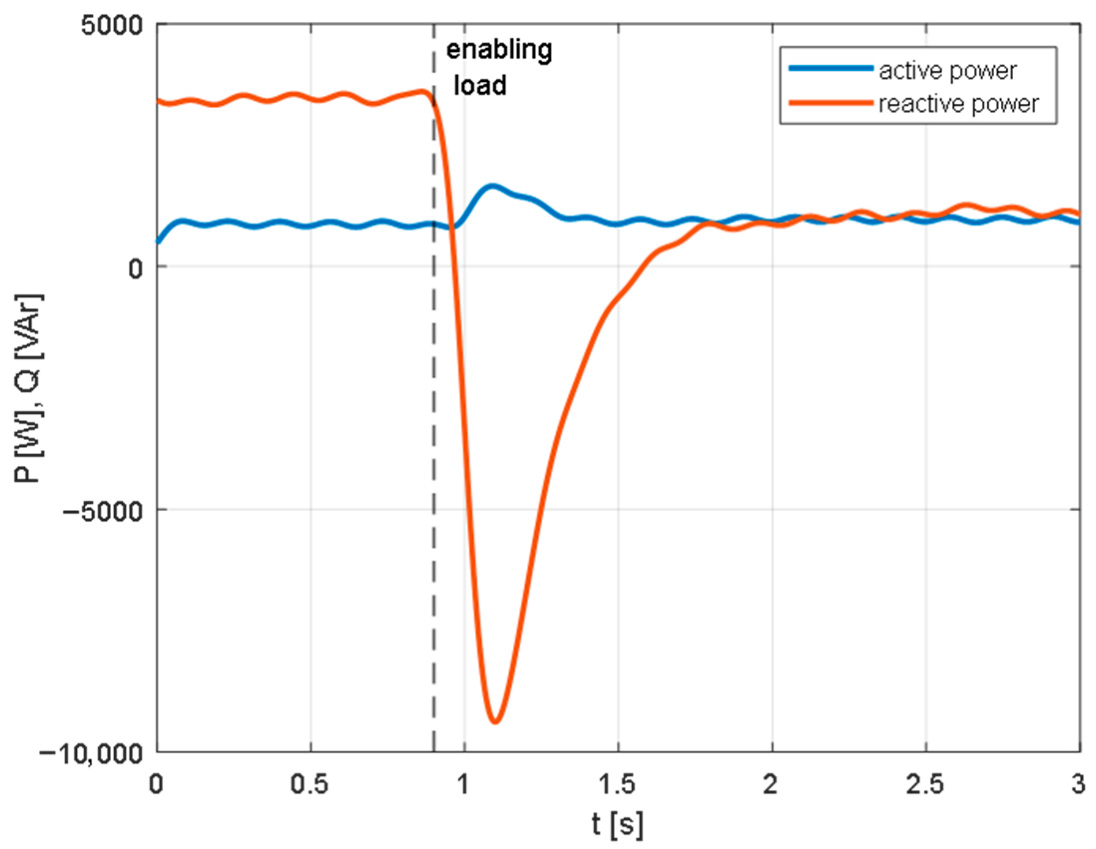
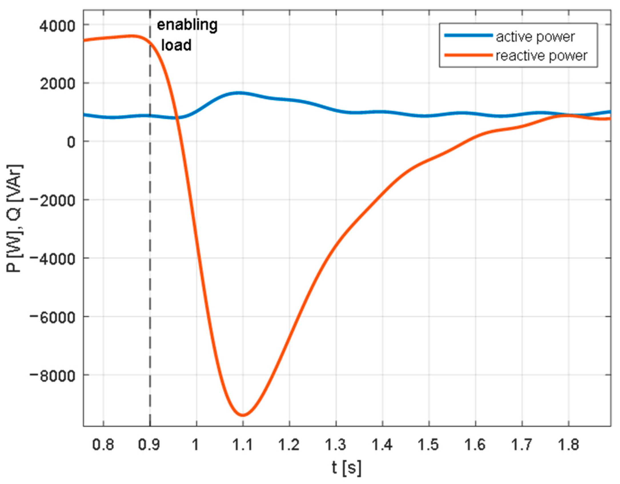
Before the load being connected, the DFIG draws 1 kW of active power and 3 kVAr of reactive power from the grid, as illustrated in Figure 11 (magnification of the waveform see Figure 12). Following the connection of the load, the level of reactive power drawn decreases to compensate for the voltage drop across the network reactance and resistance. This scenario differs slightly from the simulation case; however, the reactive power behaviour remains fully consistent with the principle described in Section 2. This further confirms that the voltage fluctuation compensation algorithm, based on the reactive power control of the DFIG, is effective at various machine operating points.

5. Discussion of the Results

A comparison of the results obtained from simulations and laboratory experiments reveals a difference in the duration needed to completely compensate the voltage drop. The extended response delay observed in the laboratory configuration is predominantly attributable to the behaviour of genuine system components that have been ignored in the simulation model [31]. In the simulation, the compensation time was determined exclusively by the actions of the controllers in the control system. In contrast, in the laboratory setup, additional delays arise from the converter operation time [32], the DSP control loop frequency [33], and transient states within the generator itself [34]. However, the results obtained in the laboratory system are entirely satisfactory. The response to voltage fluctuations is characterised by an exceptionally brief delay, thus ensuring the system’s capacity to effectively compensate for rapid variations.

6. Conclusions

The present paper sets out the implementation of reactive power control in DFIG-based generators connected to the power grid to stabilise voltage fluctuations. The findings indicate that compensating voltage variations through the implementation of reactive power control constitutes an effective approach, particularly within systems characterised by a high penetration of renewable energy sources. The results of the simulations and experimental tests demonstrate that the proposed technique facilitates a response time of less than 500 milliseconds. Moreover, a main benefit of the proposed method is its compatibility with the existing infrastructure of wind power plants, which requires only software modifications. This feature has been shown to result in a substantial reduction in the high costs typically associated with alternative solutions that require additional hardware components.
However, it should be noted that there are certain limitations with regard to the practical implementation of the proposed approach, including the interdependence between the reactive and active power of individual DFIG units. This limitation can be mitigated by increasing the apparent power margin of the generators, as well as through reactive power dispatch coordination among multiple DFIGs. Another significant constraint pertains to the efficacy of voltage fluctuation compensation, which is contingent on network reactance. This reactance is, in turn, determined by the electrical distance to the Point of Common Coupling (PCC), that is, the equivalent network impedance observed from the PCC. Therefore, to facilitate practical implementation, these constraints must be addressed, for instance, by distributing the reactive power demand among multiple generators.
In conclusion, the proposed method offers an economically and technically viable solution to improve voltage stability in modern power grids as the integration of renewable energy sources continues to grow.

Author Contributions

Conceptualization, T.L.; Methodology, T.L.; Validation, T.L.; Investigation, R.-E.N.; Resources, R.-E.N.; Data curation, R.-E.N.; Writing—original draft, R.-E.N. All authors have read and agreed to the published version of the manuscript.

Funding

Research project partly supported by program “Excellence initiative—research university” for AGH University of Krakow.

Data Availability Statement

The original contributions presented in this study are included in the article. Further inquiries can be directed to the corresponding author.

Conflicts of Interest

The authors declare that they have no conflict of interest.

References

  1. Li, B.; Liu, Y.; Li, H.; Zhao, L.; Wang, Y.; Zhang, Y.; Liu, F. Research on the Difference Between New Power System and Traditional Power System. In Proceedings of the 2024 3rd International Conference on Social Sciences and Humanities and Arts (SSHA 2024); Sedon, M.F.B., Khan, I.A., Birkök, M.C., Chan, K., Eds.; Advances in Social Science, Education and Humanities Research; Atlantis Press SARL: Paris, France, 2024; Volume 851, pp. 146–153. ISBN 978-2-38476-258-3. [Google Scholar]
  2. Hu, J.-L.; Chuang, M.-Y. The Importance of Energy Prosumers for Affordable and Clean Energy Development: A Review of the Literature from the Viewpoints of Management and Policy. Energies 2023, 16, 6270. [Google Scholar] [CrossRef]
  3. Ejuh Che, E.; Roland Abeng, K.; Iweh, C.D.; Tsekouras, G.J.; Fopah-Lele, A. The Impact of Integrating Variable Renewable Energy Sources into Grid-Connected Power Systems: Challenges, Mitigation Strategies, and Prospects. Energies 2025, 18, 689. [Google Scholar] [CrossRef]
  4. Ratchawang, K.; Hoonchareon, N. Impact of Prosumers’ PV Reverse Power Flow on Voltage Rise in MV Distribution Systems. In Proceedings of the 2023 20th International Conference on Electrical Engineering/Electronics, Computer, Telecommunications and Information Technology (ECTI-CON), Nakhon Phanom, Thailand, 9–12 May 2023; IEEE: Piscataway, NJ, USA, 2023; pp. 1–4. [Google Scholar]
  5. Alkhamıs, O.A.; İdiz, İ.; Karahan, B.; Adıgüzel, N.H.; Alptekin, H.; Erol, E.E. Study of Doubly Fed Induction Generator (DFIG) Performance by Modeling & Simulation. Res. Sq. 2025, preprint. [Google Scholar] [CrossRef]
  6. Ramesh, R.R.; Vahabzadeh, T.; Jatskevich, J. Constant-Parameter VBR Synchronous Machine Model for Studies of Unbalanced Faults in PSCAD. In Proceedings of the 2024 23rd International Symposium INFOTEH-JAHORINA (INFOTEH), East Sarajevo, Bosnia and Herzegovina, 20–22 March 2024; IEEE: Piscataway, NJ, USA, 2024; pp. 1–6. [Google Scholar]
  7. Cholahan, V.; Wongvanich, N.; Tangsrirat, W. Robust Constant Exponent Coefficient Fixed-Time Control Based on Finite-Time Extended Sliding Mode Observer of Permanent Magnet Synchronous Motors. Energies 2023, 16, 7454. [Google Scholar] [CrossRef]
  8. Li, S.; Deng, C.; Shu, Z.; Huang, W.; He, J.; You, Z. Equivalent Inertial Time Constant of Doubly Fed Induction Generator Considering Synthetic Inertial Control. J. Renew. Sustain. Energy 2016, 8, 053304. [Google Scholar] [CrossRef]
  9. Wang, W.; Huang, G. Impacts of DFIG Reactive Power/Voltage Control on Power System Oscillations through Mode Coupling. In Proceedings of the Qatar Foundation Annual Research Conference Proceedings, Doha, Qatar, 19–20 March 2018; Hamad bin Khalifa University Press (HBKU Press); Qatar National Convention Center (QNCC): Doha, Qatar, 2018; Volume 2018. [Google Scholar]
  10. Fedele, E.; Lauria, D.; Rizzo, R. DFIG Capability under Weak Grid Connection and Different Reactive Power Control Modes. In Proceedings of the 2023 International Conference on Clean Electrical Power (ICCEP), Terrasini, Italy, 27–29 June 2023; IEEE: Piscataway, NJ, USA, 2023; pp. 896–902. [Google Scholar]
  11. WindEurope. Latest Wind Energy Data for Europe: Autumn 2024. Available online: https://windeurope.org/data/products/latest-wind-energy-data-for-europe-autumn-2024/ (accessed on 15 July 2025).
  12. Ilambirai, R.C.; Kanthimathi, T.; Thimmarayan, R.; Sagar, B.S. Advanced Dvr Control with Iot for Voltage Sag Compensation in Wind-Connected Power Grids. Int. J. Adv. Signal Image Sci. 2025, 11, 94–103. [Google Scholar] [CrossRef]
  13. Farhadi-Kangarlu, M.; Babaei, E.; Blaabjerg, F. A Comprehensive Review of Dynamic Voltage Restorers. Int. J. Electr. Power Energy Syst. 2017, 92, 136–155. [Google Scholar] [CrossRef]
  14. Ital, A.V.; Borakhade, S.A. Compensation of Voltage Sags and Swells by Using Dynamic Voltage Restorer (DVR). In Proceedings of the 2016 International Conference on Electrical, Electronics, and Optimization Techniques (ICEEOT), Chennai, India, 3–5 March 2016; IEEE: Piscataway, NJ, USA, 2016; pp. 1515–1519. [Google Scholar]
  15. Selvam, P.; Sathish, R.; Marimuthu, M.; Loganathan, P.; Devarajan, R.; Vinod Kumar, D. Improving the Quality of Power by Compensating Voltage Sag Compensation Using Dynamic Voltage Restorer. In Proceedings of the 2022 International Conference on Augmented Intelligence and Sustainable Systems (ICAISS), Trichy, India, 24–26 November 2022; IEEE: Piscataway, NJ, USA, 2022; pp. 1460–1465. [Google Scholar]
  16. Apata, O.; Oyedokun, D.T.O. Novel Reactive Power Compensation Technique for Fixed Speed Wind Turbine Generators. In Proceedings of the 2018 IEEE PES/IAS PowerAfrica, Cape Town, South Africa, 28–29 June 2018; IEEE: Piscataway, NJ, USA, 2018; pp. 628–633. [Google Scholar]
  17. Tripathy, M.; Samal, R.K. A New Perspective on Wind Integrated Optimal Power Flow Considering Turbine Characteristics, Wind Correlation and Generator Reactive Limits. Electr. Power Syst. Res. 2019, 170, 101–115. [Google Scholar] [CrossRef]
  18. Edrisian, A.; Goudarzi, A.; Davidson, I.E.; Ahmadi, A.; Venayagamoorthy, G.K. Enhancing SCIG-Based Wind Turbine Generator Performance through Reactive Power Control. In Proceedings of the 2015 Clemson University Power Systems Conference (PSC), Clemson, SC, USA, 10–13 March 2015; IEEE: Piscataway, NJ, USA, 2015; pp. 1–8. [Google Scholar]
  19. Srirattanawichaikul, W. Modified Coordination of Voltage-Dependent Reactive Power Control with Inverter-Based DER for Voltage Regulation in Distribution Networks. In Proceedings of the 2022 4th International Conference on Smart Power & Internet Energy Systems (SPIES), Beijing, China, 9–12 December 2022; IEEE: Piscataway, NJ, USA, 2022; pp. 20–25. [Google Scholar]
  20. Mascarella, D.; Li, S.; Joos, G.; Venne, P. Reactive Power Coordination in DFIG Based Wind Farms for Voltage Regulation & Flicker Mitigation. In Proceedings of the 2015 IEEE Power & Energy Society General Meeting, Denver, CO, USA, 26–30 July 2015; IEEE: Piscataway, NJ, USA, 2015; pp. 1–5. [Google Scholar]
  21. Fukushima, K.; Nayuki, T.; Hatta, H.; Kobayashi, H. Voltage Regulation in Low-Voltage Distribution Grids with Reactive Power Control by Power Conditioning Subsystem Coordination. In Proceedings of the 2019 International Conference on Smart Energy Systems and Technologies (SEST), Porto, Portugal, 9–11 September 2019; IEEE: Piscataway, NJ, USA, 2019; pp. 1–5. [Google Scholar]
  22. Lerch, T.; Barczentewicz, S.; Abu Sarhan, M.; Feng, Z.; Burt, G. Grid Tie Converters Aided Rapid Grid Voltage Fluctuation Compensation with Power Hardware-in-the-Loop Experimental Validation. Elektrotech. Inform. 2025, 142, 42–50. [Google Scholar] [CrossRef]
  23. Lee, Y.; Song, H. A Reactive Power Compensation Strategy for Voltage Stability Challenges in the Korean Power System with Dynamic Loads. Sustainability 2019, 11, 326. [Google Scholar] [CrossRef]
  24. Nassif, A.B.; Fedaku, D. A Reactive Power Compensation Scheme Using Distribution STATCOMs to Manage Voltage in Rural Distribution Systems. In Proceedings of the 2020 IEEE Electric Power and Energy Conference (EPEC), Edmonton, AB, Canada, 9–10 November 2020; IEEE: Piscataway, NJ, USA, 2020; pp. 1–5. [Google Scholar]
  25. Pal, R.; Gupta, S. Topologies and Control Strategies Implicated in Dynamic Voltage Restorer (DVR) for Power Quality Improvement. Iran. J. Sci. Technol. Trans. Electr. Eng. 2020, 44, 581–603. [Google Scholar] [CrossRef]
  26. Iorgulescu, M.; Ursu, D. Reactive Power Control and Voltage Stability in Power Systems. In Reactive Power Control in AC Power Systems; Mahdavi Tabatabaei, N., Jafari Aghbolaghi, A., Bizon, N., Blaabjerg, F., Eds.; Power Systems; Springer International Publishing: Cham, Switzerland, 2017; pp. 227–248. ISBN 978-3-319-51117-7. [Google Scholar]
  27. Kabalci, E. Reactive Power Compensation in AC Power Systems. In Reactive Power Control in AC Power Systems; Mahdavi Tabatabaei, N., Jafari Aghbolaghi, A., Bizon, N., Blaabjerg, F., Eds.; Power Systems; Springer International Publishing: Cham, Switzerland, 2017; pp. 275–315. ISBN 978-3-319-51117-7. [Google Scholar]
  28. Lamb, J.; Mirafzal, B. Active and Reactive Power Operational Region for Grid-Tied Inverters. In Proceedings of the 2016 IEEE 7th International Symposium on Power Electronics for Distributed Generation Systems (PEDG), Vancouver, BC, Canada, 27–30 June 2016; IEEE: Piscataway, NJ, USA, 2016; pp. 1–6. [Google Scholar]
  29. Fihakhir, A.M.; Guerbouz, A. Control of DFIG Active and Reactive Power Dedicated for Wind Turbine. In Proceedings of the 2024 12th International Conference on Systems and Control (ICSC), Batna, Algeria, 3–5 November 2024; IEEE: Piscataway, NJ, USA, 2024; pp. 377–382. [Google Scholar]
  30. Suntio, T.; Hankaniemi, M.; Karppanen, M. Analysing the Dynamics of Regulated Converters. IEE Proc.-Electr. Power Appl. 2006, 153, 905–910. [Google Scholar] [CrossRef]
  31. Abouseda, A.I.; Doruk, R.; Emin, A.; Akdeniz, O. Modeling, Dynamic Characterization, and Performance Analysis of a 2.2 kW BLDC Motor Under Fixed Load Torque Levels and Variable Speed Inputs: An Experimental Study. Actuators 2025, 14, 400. [Google Scholar] [CrossRef]
  32. Bevrani, H.; Kato, T.; Ise, T.; Inoue, K. Modeling and Dynamic Performance of Grid Connected Converters. In Grid Connected Converters; Elsevier: Amsterdam, The Netherlands, 2022; pp. 45–75. ISBN 978-0-323-99902-1. [Google Scholar]
  33. Corradini, L.; Maksimović, D.; Mattavelli, P.; Zane, R. Digital Control of High-Frequency Switched-Mode Power Converters, 1st ed.; Wiley: Hoboken, NJ, USA, 2015; ISBN 978-1-118-93510-1. [Google Scholar]
  34. Xu, Z.; He, J.; Xie, Z. Analysis of DFIG Transient Process Based on Drive-Chain. In Proceedings of the 2016 35th Chinese Control Conference (CCC), Chengdu, China, 27–29 July 2016; IEEE: Piscataway, NJ, USA, 2016; pp. 8749–8753. [Google Scholar]
Figure 1. Restrictions on reactive power based on the operating point (authors’ own work).
Energies 19 00105 g001
Figure 2. Summation model of the voltage fluctuation compensation system with DFIG (authors’ own work).
Energies 19 00105 g002
Figure 3. The voltage waveform during the simulation in the first scenario (authors’ own work).
Energies 19 00105 g003
Figure 4. The active and reactive power waveforms during the simulation in the first scenario (authors’ own work).
Energies 19 00105 g004
Figure 5. The voltage waveform during the simulation in the second scenario (authors’ own work).
Energies 19 00105 g005
Figure 6. The active and reactive power waveforms during the simulation in the second scenario (authors’ own work).
Energies 19 00105 g006
Figure 7. Diagram of a laboratory setup with a voltage fluctuation compensation system with DFIG (authors’ own work).
Energies 19 00105 g007
Figure 8. Set of machines on a lab bench (authors’ own work).
Energies 19 00105 g008
Figure 9. The measurement system used in the laboratory setup (authors’ own work). Uab, Ubc—stator line voltages; Isa, Isb—stator currents; Ira, Irb—rotor currents; enc.—encoder.
Energies 19 00105 g009
Figure 10. The voltage waveform during the laboratory experiment (authors’ own work).
Energies 19 00105 g010
Figure 11. Active and reactive power waveforms during the laboratory experiment (authors’ own work).
Energies 19 00105 g011
Figure 12. The active and reactive power waveforms-magnification of the waveform (authors’ own work).
Energies 19 00105 g012
Disclaimer/Publisher’s Note: The statements, opinions and data contained in all publications are solely those of the individual author(s) and contributor(s) and not of MDPI and/or the editor(s). MDPI and/or the editor(s) disclaim responsibility for any injury to people or property resulting from any ideas, methods, instructions or products referred to in the content.