Article

Design of a Novel Nine-Phase Ferrite-Assisted Synchronous Reluctance Machine with Skewed Stator Slots

by
Hongliang Guo
1,2,
Tianci Wang
1,2,
Hongwu Chen
1,2,
Zaixin Song
1,2 and
Chunhua Liu
1,2,*
1
School of Energy and Environment, City University of Hong Kong, Hong Kong, China
2
Shenzhen Research Institute, City University of Hong Kong, Shenzhen 518057, China
*
Author to whom correspondence should be addressed.
Energies 2025, 18(9), 2323; https://doi.org/10.3390/en18092323
Submission received: 4 April 2025 / Revised: 25 April 2025 / Accepted: 29 April 2025 / Published: 2 May 2025
(This article belongs to the Special Issue Advanced Technologies for Electrified Transportation and Robotics)

Abstract

:
This paper proposes a novel nine-phase ferrite-assisted synchronous reluctance machine (FA-SynRM) featuring skewed stator slots to address challenges related to harmonic distortion, torque ripple, and material sustainability which are prevalent in conventional permanent magnet-assisted synchronous reluctance motors (PMa-SynRMs). Existing PMa-SynRMs often suffer from increased torque ripples and harmonic distortion, while reliance on rare-earth materials raises cost and sustainability concerns. To address these issues, the proposed design incorporates low-cost ferrite magnets embedded within the rotor flux barriers to achieve a flux-concentrated effect and enhanced torque production. The nine-phase winding configuration is utilized to improve fault tolerance, reduce harmonic distortion, and enable smoother torque output compared with conventional three-phase counterparts. In addition, the skewed stator slot design further minimizes harmonic components, reducing overall distortion. The proposed machine is validated through finite element analysis (FEA), and experimental verification is obtained by measuring the inductance characteristics and back-EMF of the nine-phase winding, confirming the feasibility of the electromagnetic design. The results demonstrate significant reductions in harmonic distortion and torque ripples, verifying the potential of this design.

1. Introduction

Synchronous reluctance machines (SynRMs) have garnered significant interest due to their simplicity, robust structure, and ability to achieve high efficiency without the need for permanent magnets (PMs) or windings on the rotor [1,2,3]. These characteristics make them cost-effective and sustainable solutions for various applications in the fields of high-density wearable robotic actuators [4], electric vehicle traction [5,6], and aerospace propulsion [7,8,9]. However, SynRMs rely solely on reluctance torque, which limits their torque and power density compared with permanent magnet synchronous machines (PMSMs) [10,11]. This constraint has motivated hybrid solutions such as permanent magnet-assisted synchronous reluctance machines (PMa-SynRMs), which combine the high torque and power density of PMSMs with the efficiency and robustness of SynRMs by embedding PMs within the flux barriers of the salient rotor core [12,13]. While this design significantly improves performance by combining reluctance torque with magnetic torque, it reintroduces a dependency on rare-earth-based PMs, posing challenges in terms of cost, sustainability, and supply-chain stability. To address these challenges, ferrite magnets, a low-cost and widely available alternative, are increasingly being adopted. The resulting machine is called a ferrite-assisted synchronous reluctance machine (FA-SynRM). The use of such machines reduces reliance on rare-earth materials, offering a sustainable pathway while maintaining competitive machine performance [14,15].
In parallel, the development of multiphase machines has opened new opportunities to enhance reliability and performance [16,17,18]. Compared with traditional three-phase systems, multiphase configurations offer inherent fault tolerance and operational redundancy [19,20,21]. These features ensure continuous operation under certain fault conditions, making multiphase machines particularly suitable for safety-critical applications [22]. Additionally, the distributed nature of multiphase systems enables smoother torque output and reduced harmonic distortion, which are critical for high-precision, high-reliability applications such as wearable robotics and wireless motor systems [23,24]. These advantages align well with the goals of improving performance and reliability in FA-SynRM designs. An example of such integration is shown in Figure 1, which depicts a schematic diagram of a powered lower-limb exoskeleton incorporating the FA-SynRM. The exoskeleton consists of three modules: the torso module, the wearable robotic actuator powered by the FA-SynRM, and the thigh support. Movement of the powered hip exoskeleton is achieved by two single-axis revolute joints for hip flexion/extension joints mounted on the lateral leg. However, despite these benefits, multiphase configurations also present certain challenges. For instance, while fault tolerance is improved, issues such as increased PM losses and cogging torque can arise [25]. Reduced power per phase also means that the rated current or voltage has to be rescaled [26]. Additionally, the five-phase SynRM described in [19], though capable of achieving higher torque with reduced ripple, tends to generate localized hotspots in typical slots, potentially affecting thermal management. These factors must be carefully considered when optimizing multiphase machine designs for real-world applications.
Beyond the selection of magnets and phase configuration, the stator core design significantly impacts machine performance. One persistent challenge with FA-SynRMs is to achieve increased torque density with low torque ripple; this is because of their high saliency and complicated flux barrier design. A preferred strategy for ripple suppression in electric machines is the skewing method, which minimizes non-working harmonic components and significantly reduces cogging torque and torque ripple [27,28,29].
In recent years, PMa-SynRMs have been extensively investigated due to their potential to achieve a balance among high efficiency, robustness, and torque density. A key approach to realizing these objectives involves employing asymmetrical rotor configurations. For instance, studies such as [30,31] introduced asymmetrical rotor topologies designed to align the peaks of magnetic and reluctance torque, thereby improving overall torque production and efficiency. In [32] a V-shaped ferrite magnet was proposed to align torque peaks and at the same time lower PM volume, while [33] explored diverted rotor geometries to enhance torque density. Although these modifications offered tangible performance benefits, they also introduced manufacturing complexities that warrant careful consideration. Beyond asymmetrical innovations to improve torque production, other studies have emphasized reducing torque ripple and improving material utilization. For example, Ref. [34] incorporated axially integrated magnets to mitigate torque ripple, whereas [35,36] focused on optimizing flux barriers in rare-earth-based PMa-SynRMs to achieve smoother operation. These efforts highlight an inherent trade-off: while increasingly complex machine structures can suppress torque ripple, they also raise manufacturing challenges.
In addition to achieving performance improvements, researchers have carried out significant work to address the sustainability and cost concerns associated with rare-earth PM materials by reducing their usage or replacing them entirely. In [37], a high-power-density FA-SynRM was investigated and found to demonstrate torque densities comparable with those of rare-earth machines, albeit with the need for demagnetization considerations at low temperatures. Similarly, Ref. [38] explored FA-SynRMs in heavy-duty traction applications, addressing mechanical safety and torque ripple issues, but extreme operating conditions posed further optimization challenges. The authors of [39] introduced anisotropic rotor structures with ferrite magnets to achieve competitive torque density; however, this approach required increased machine stack length to compensate for the less potent magnetic material. Hybrid PM designs are also viewed as an effective strategy to reduce dependency on rare-earth materials. For instance, Ref. [22] introduced hierarchical flux barriers incorporating both rare-earth and ferrite PMs to achieve a balance between efficiency and torque ripple suppression. Finally, Ref. [23] proposed a reduction in rare-earth PM usage for traction applications, significantly decreasing PM volume while facing the challenge of potential demagnetization under overload conditions. Despite these advancements, persistent difficulties remain—particularly in managing torque ripple, maintaining adequate torque production, addressing rotor complexity, and ensuring overall material sustainability. Therefore, this paper proposes a novel nine-phase PMa-SynRM featuring ferrite magnets and skewed stator slots to address these limitations and thereby achieve a balance between cost and performance.
The structure of this paper is organized as follows: Section 2 describes the topology and working principle of the proposed FA-SynRM. Section 3 focuses on the electromagnetic performance analysis, conducted using finite element analysis (FEA, version: Jmag) software. Section 4 presents the prototype and the phase inductance measurement results. Finally, Section 5 summarizes the key conclusions drawn from this study.

2. Machine Topology and Working Principle

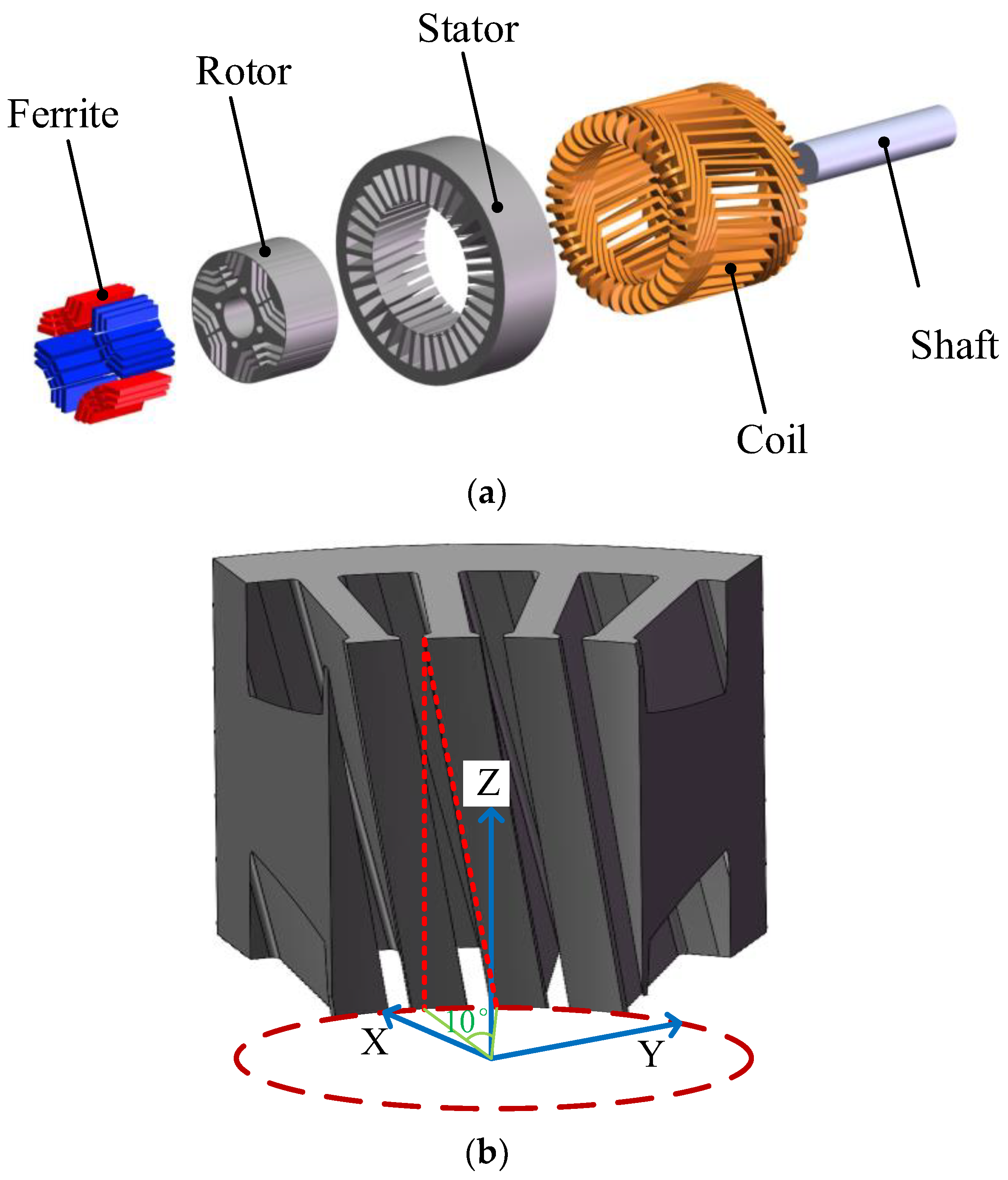
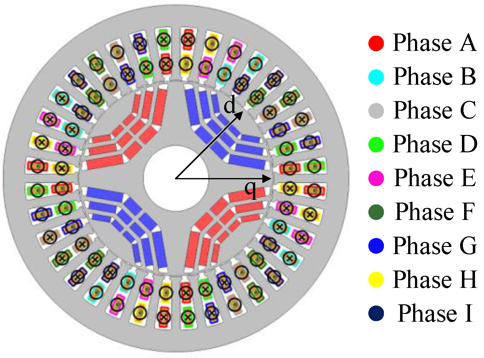
2.1. Machine Topology

The 3-D model of FA-SynRM proposed in this paper is shown in Figure 2. The FA-SynRM has 36 slots, each of which is skewed by one slot pitch across the axial direction. For the rotor part, there are three layers of flux barriers per pole. The low-cost ferrite is settled in these barriers. Each pole consists of four groups of ferrites with the same polarity, with two groups of ferrites on sides and two groups in the middle so that a magnetic flux-concentrated effect can be achieved to improve the torque. Distributed winding is adopted which is double-layered and composed of series-connected coils of nine phases, with each coil winding across eight slots. The distribution of the nine-phase coils is shown in the front cross-section view of the proposed FA-SynRM in Figure 3.
The proposed nine-phase windings are split into three sets of conventional three-phase windings. The displacement of the three sets of windings can be 20 or 0 electrical degrees. The configuration is shown in Figure 3. The 20 electrical degree displacement scheme in Figure 4a is employed in the proposed design. The 0 electrical degree displacement scheme in Figure 4b is equivalent to a conventional three-phase scheme with a 60 electrical degree phase spread. The machine performance under the two schemes are compared in detail in the following sections.

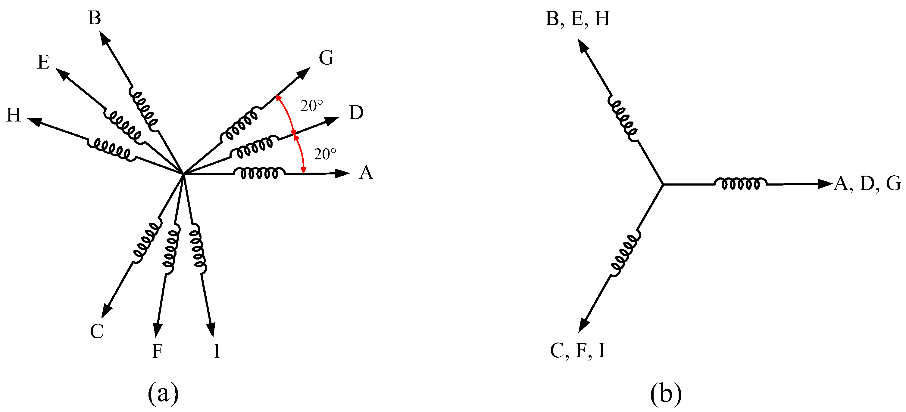
2.2. Working Principle

The FA-SynRM generates torque through a combination of reluctance torque and magnetic torque. The rotor is designed with embedded ferrite magnets placed within flux barriers, forming a salient rotor structure with distinct d-axis and q-axis reluctances. Reluctance torque arises from the rotor’s anisotropic geometry, where the d-axis exhibits higher reluctance than the q-axis, causing the rotor to align with the stator’s rotating magnetic field to minimize magnetic reluctance. At the same time, the embedded ferrite magnets generate magnetic torque by interacting with the stator’s magnetic field, providing an additional torque component that enhances overall torque output. This dual-torque production mechanism allows the FA-SynRM to reduce stator current requirements for a given torque demand, improving overall performance.
Because the proposed FA-SynRM has a 4-pole structure, the magnetic torque varies periodically with the angular position of the rotor. Specifically, the magnetic torque changes polarity every 90 mechanical degrees, corresponding to the alignment of ferrite magnets with opposite polarities. When at the original q-axis (as shown in Figure 5), the magnetic field contribution from the ferrite magnets set is zero. As the rotor moves anticlockwise toward the d-axis, which is located 45 mechanical degrees from the original q-axis, the magnetic flux density increases to its maximum value. Beyond this point, the magnetic field contribution gradually decreases, reaching zero again at the next q-axis located 90 mechanical degrees from the original one. Similarly, the reluctance torque varies periodically as the rotor moves between the d- and q-axes, but its period is half that of the magnetic torque. Figure 5a illustrates the waveforms of reluctance torque, PM torque, and total torque. It is notable that the two torque components do not reach their peak values at the same phase angle where they are displaced by 45° with respect to each other. This dual-torque mechanism allows FA-SynRMs to leverage the advantages of both reluctance and magnetic torque, reducing stator current for a given torque demand and improving overall machine performance.
The phasor diagram of the FA-SynRM, shown in Figure 5b, is derived from the d-q rotor frame equivalent circuit using the Park transformation. In this configuration, the d-axis aligns with the PM poles, resulting in the PM flux linkage vector ΨPM lying entirely along the d-axis. The electromagnetic torque can be expressed mathematically as a combination of the torque contributions from the PM flux linkage and the differential reluctance between the d- and q-axes [40]:
T e = 9 p 2 L d L q i d i q + Ψ P M i q i d = I a sin θ i q = I a cos θ
where p represents the number of pole pairs, I a is the amplitude of the phase current, and θ is the current phase angle, which is the angle of the stator current vector with respect to the q-axis. L d and L q are the inductances along the d- and q-axes, respectively, while Ψ P M is the peak fundamental value of the ferrite flux linkage. In (1), the first term, L d L q i d i q , represents the reluctance torque, whereas the second term, Ψ P M i q , corresponds to the magnetic torque.

3. Finite Element Analysis

In this section, we describe how we demonstrated the electromagnetic characteristics of the proposed FA-SynRM by building a 3D finite element analysis (FEA) model of it, with the following assumptions being made:
  • The coils are independent of each other, and mutual inductance between windings is ignored.
  • The material permeability and conductivity of the core are assumed to be homogeneous and isotropic.
  • The ferrite properties, such as remanence and coercivity, remain constant and are not affected by temperature or demagnetization.
  • Thermal effects on the resistivity of windings are not considered.
  • The air gap is assumed to be perfectly uniform.
  • The ferrite PM losses are assumed to be negligible compared with the iron loss.
The main geometric specifications of the proposed machine are listed below in Table 1, and the flux distribution of the proposed machine under rated conditions is shown in Figure 6. From the figure, it can be observed that saturation happens mostly at the bridges which is intentionally designed to avoid flux leakages. To verify the effectiveness of the skewed slot design and multi-phase scheme, comprehensive comparative studies were carried out, as described in this section.

3.1. Comparison with Non-Skewed Stator Slots

To highlight the advantages of the proposed skewed stator, the characteristics of proposed and conventional FA-SynRMs are compared at the same operating conditions. The results under both no-load and on-load conditions are presented in the following subsections. It should be noted that because the conventional design is not skewed in the machine axial direction, 2-D FEA is preferred for it to avoid massive simulation time.

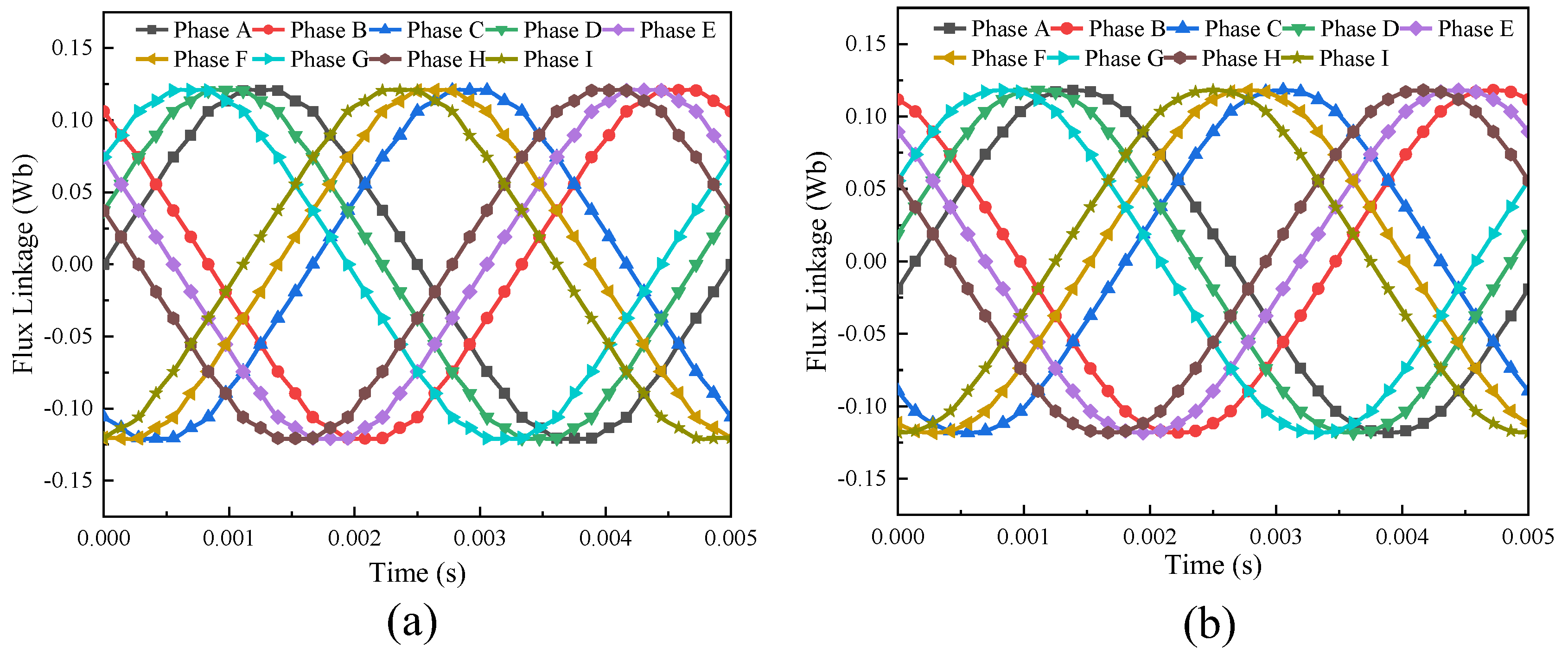
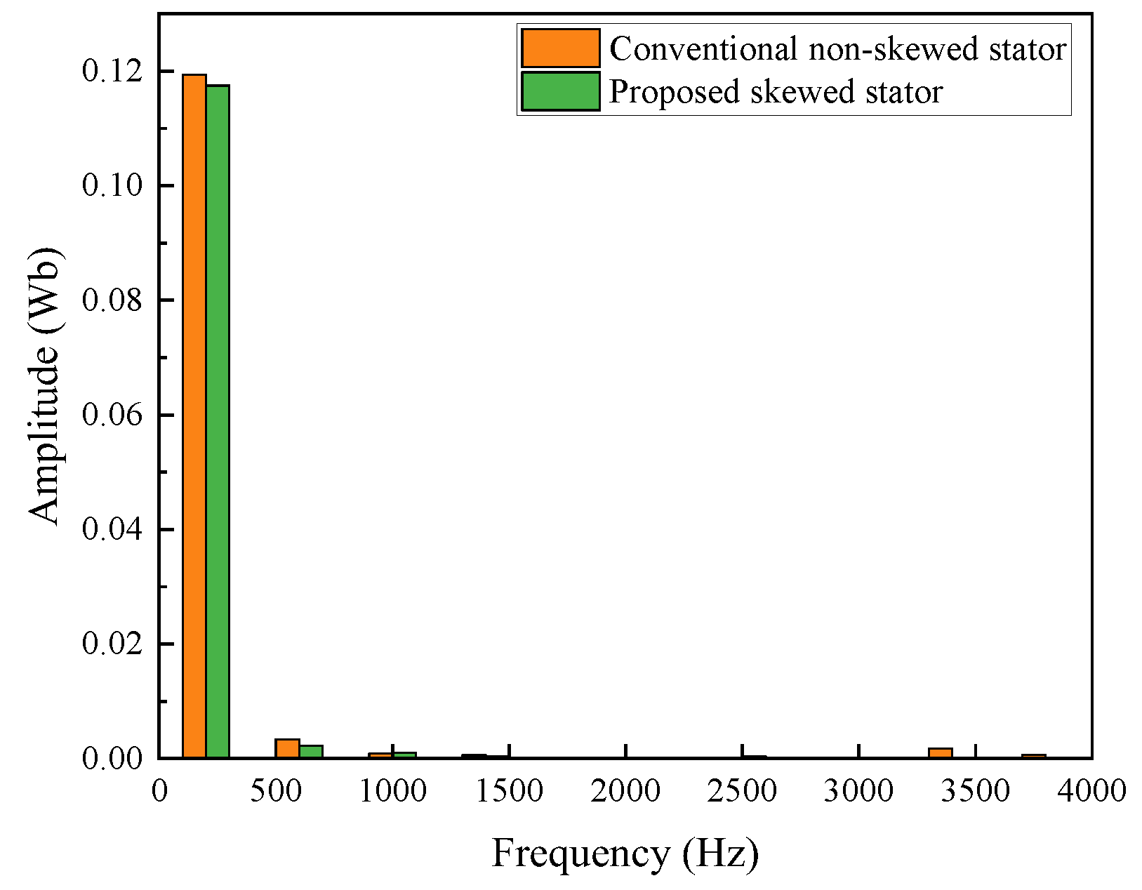
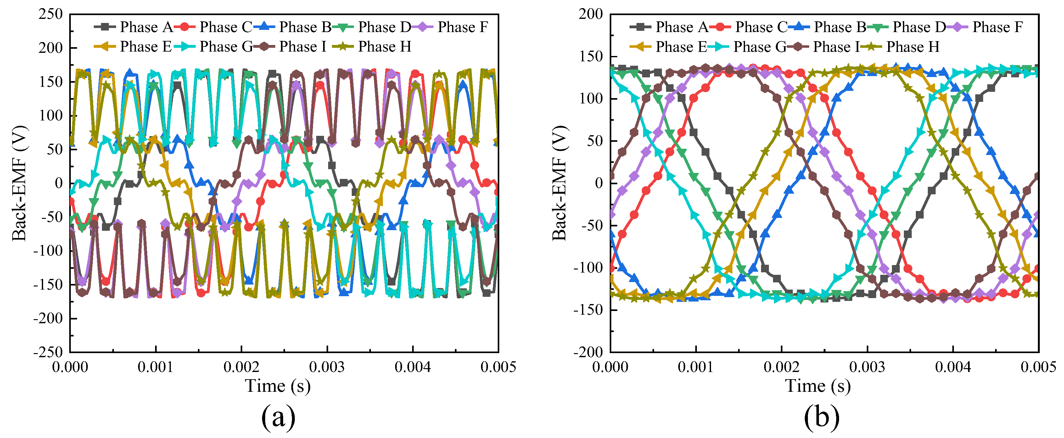
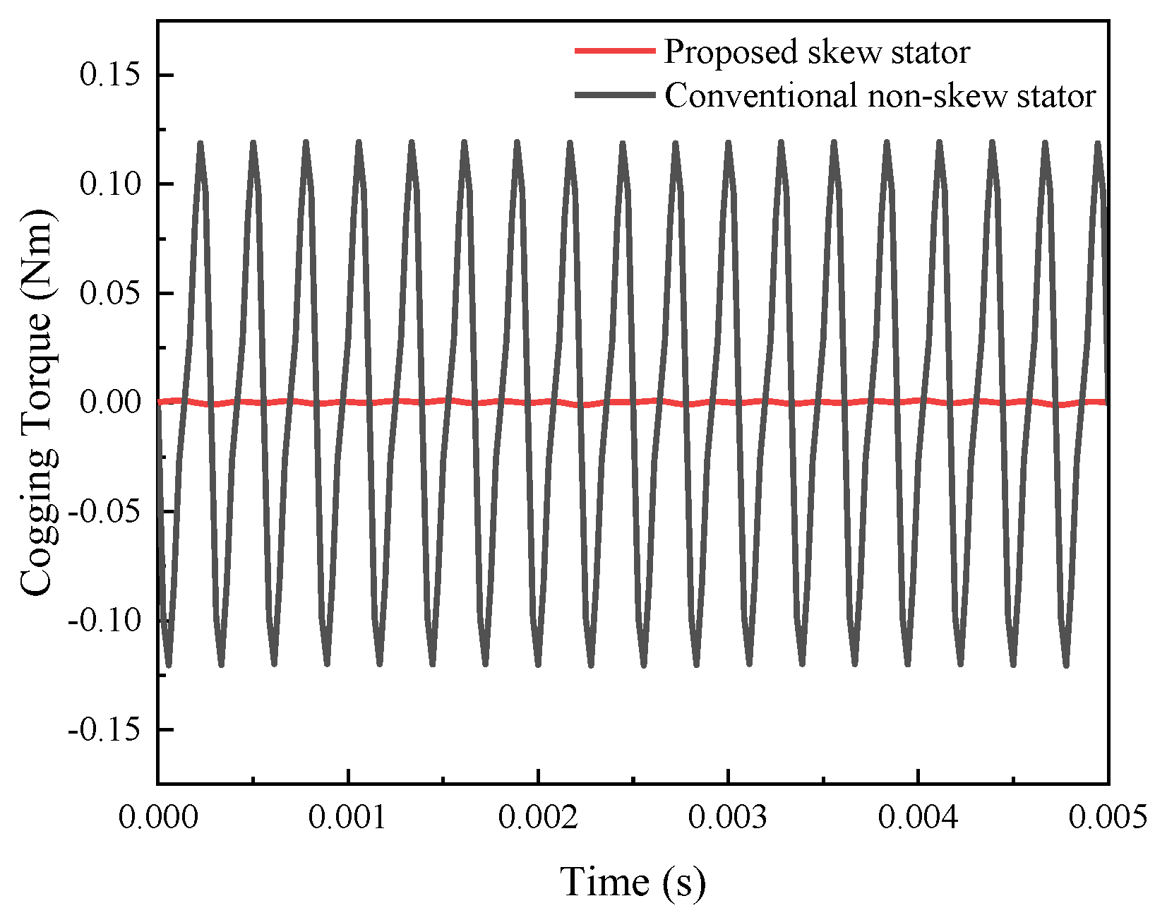
3.1.1. No-Load Analysis Between the Skewed and Non-Skewed Stator Designs

The waveforms of the no-load flux linkage for both the conventional and proposed machines are depicted in Figure 7. It can be observed that both machines exhibit nearly sinusoidal flux linkage waveforms across the nine phases; however, a subtle difference can be observed in terms of harmonic content.
To quantify these differences, the fast Fourier transform (FFT) spectra of the flux linkage waveforms are presented in Figure 8. FFT analysis reveals that the harmonic amplitudes of the proposed machine with a skewed stator slot are slightly lower than in the conventional design. The total harmonic distortion (THD) of the flux linkage is then quantified from the FFT spectra, showing that the proposed FA-SynRM achieves a THD of 2.15%, which is lower than the 3.34% achieved by the conventional machine.
Figure 9a and Figure 9b show the no-load back-EMF waveforms for the conventional FA-SynRM and the proposed machine, respectively. The conventional machine shows visibly terrible harmonic distortions in its back-EMF waveform, whereas the proposed machine demonstrates a waveform that is closer to an ideal sinusoid, although minor harmonic components are still present. This improvement in waveform quality is further supported by the FFT spectra shown in Figure 10, which indicate that the harmonic amplitudes in the proposed design are considerably lower than those in the conventional machine, especially those of high orders. From the FFT analysis, the THD of the back-EMF for the proposed machine is calculated to be 7.90%, compared with 30.91% for the conventional machine.
To analyze how skewing the stator slots reduces cogging torque, one may start from the generic harmonic model of cogging torque. In particular, one can write the resultant cogging torque T c o g as a sum of its harmonic components, often expressed in the form
T c o g = m = 1 , 2 , 3 . N s l · T n · sin 1 2 · N l c m m N s k θ s l 1 2 N l c m m N s k θ s l · sin N l c m m θ r + 1 2 · N l c m m N s k θ s l n = N l c m m 2 p
Here, N s l is the stator slot number, N l c m is the least common multiple of N s l and the total pole pair number 2 p , θ s l is the mechanical angle per slot pitch, T n is the amplitude of the n th order single-slot cogging torque component, m is an integer, N s k is a dimensionless factor that quantifies how many slot-pitches the stator slots are skewed, θ r is the rotor’s angular position. The factor sin 1 2 · N l c m m N s k θ s l / 1 2 N l c m m N s k θ s l acts as a distribution factor in this cogging-torque context. Notably, if sin 1 2 · N l c m m N s k θ s l = 0 , the corresponding harmonic component is driven to zero. This happens when
N l c m m N s k θ s l 2 = k π     N s k = 2 k π N l c m m θ s l ,   k Z
Regarding the topology of the proposed FA-SynRM, where N s l = 36 , 2 p = 4 , so N l c m = 36 , θ s l = π 18 , and n = 9 m ; substituting these into Equation (3) gives:
N s k = k m
Thus, if one chooses N s k to satisfy Equation (4), the 9 m th harmonic of the cogging torque can be suppressed entirely. Here, for the proposed design with N s k = 1 , the 9th, 18th, 27th…order harmonics of cogging torque can be eliminated. Figure 11 shows the cogging torque waveforms for both machines. The cogging torque in this case arises due to the interaction between the rotor interior ferrite magnets sets and the stator slots, which is influenced by the stator slot geometry. The proposed FA-SynRM, featuring a skewed stator slot, exhibits much smaller fluctuations in cogging torque compared with the conventional machine. The reduction in cogging torque variations observed in the proposed design implies a more consistent torque output.

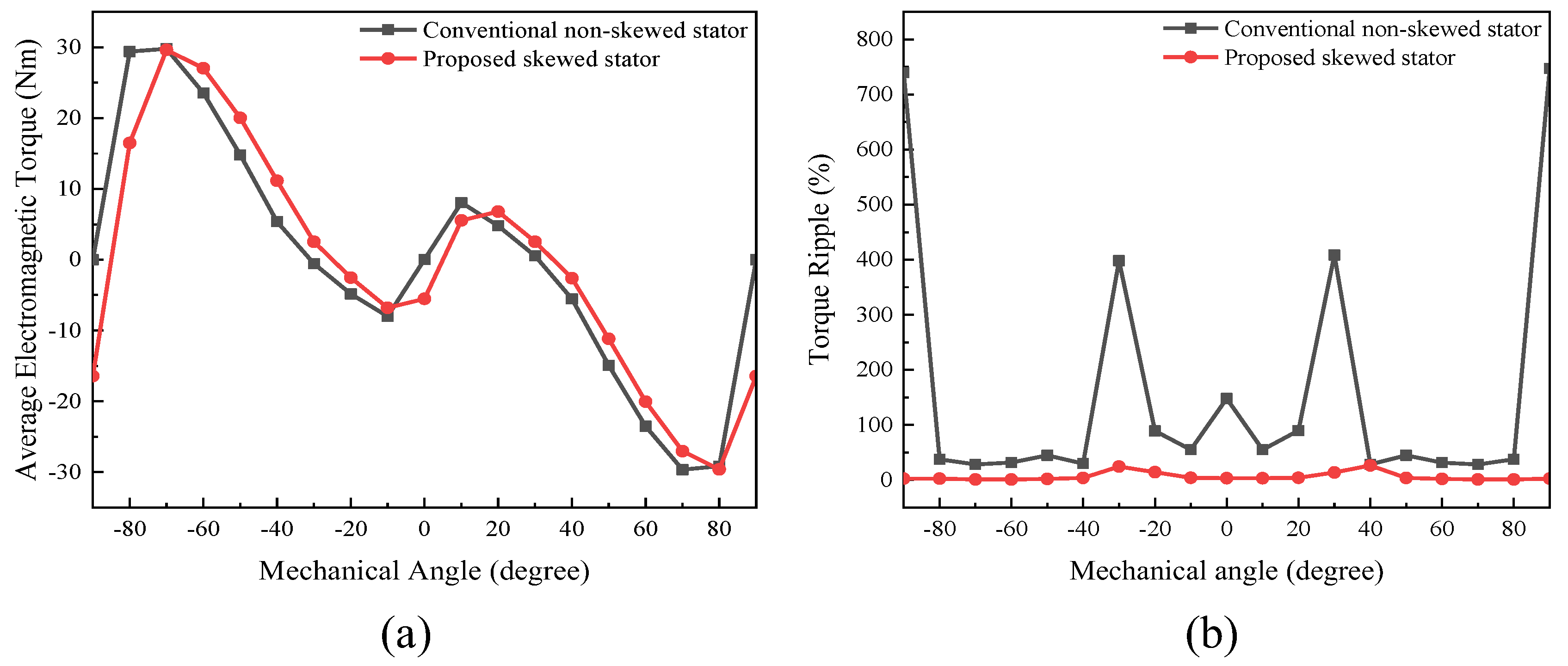
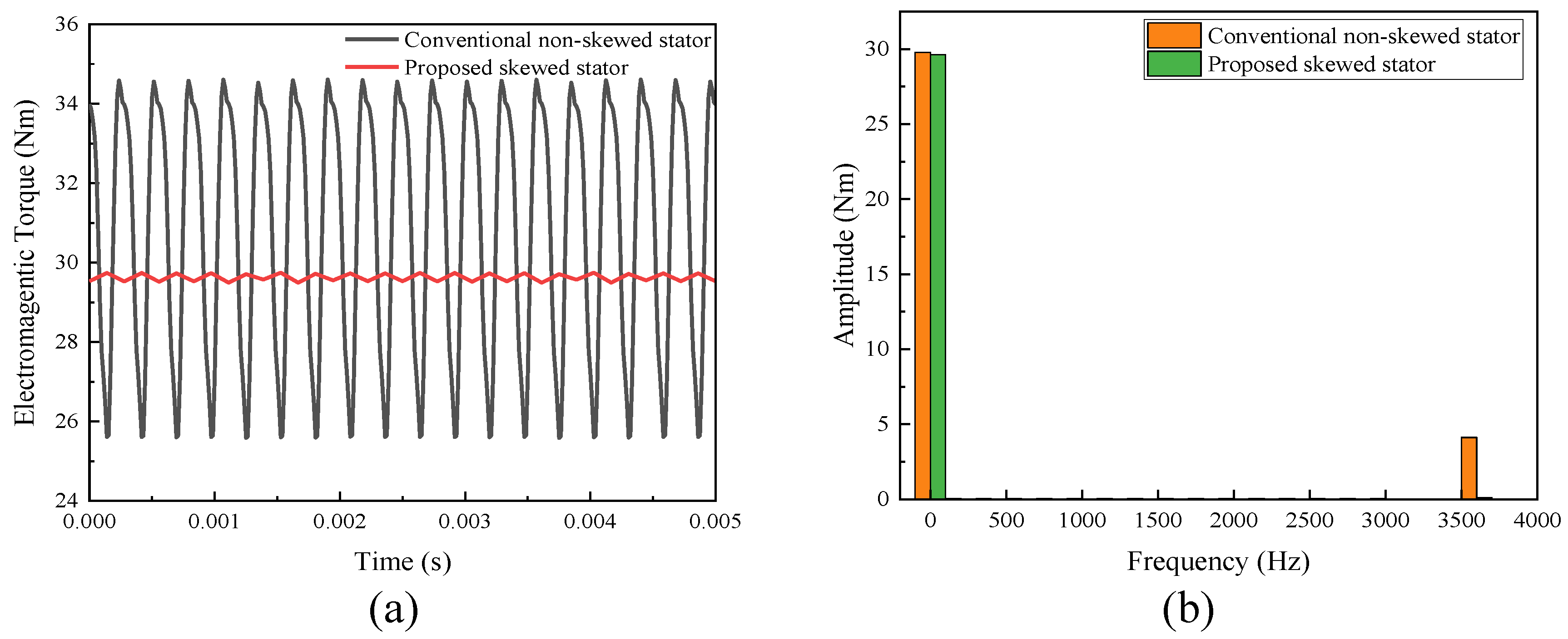
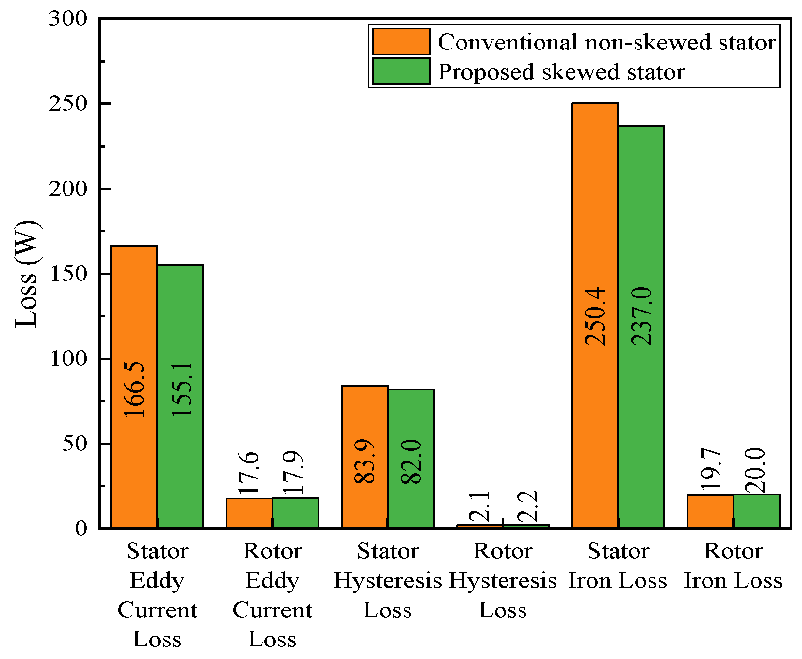
3.1.2. On-Load Analysis Between the Skewed and Non-Skewed Stator Designs

Figure 12a shows the average electromagnetic torque over a range of rotor initial mechanical angles from −90° to 90°, which corresponds to a variation in the electrical angle of the phase current from −180° to 180°. Both the proposed and conventional machines achieve their maximum positive average torque near −70°. Figure 12b presents the torque ripple characteristics over the same range of rotor initial angles. The torque ripple expressed as an absolute percentage of the average torque is significantly lower for the proposed machine, compared with the conventional design. The proposed FA-SynRM consistently maintains torque ripple percentages below 30% across all angles, with minimal variation. In contrast, the conventional machine exhibits excessively high torque ripple values, exceeding 700% at certain angles. This remarkable reduction in torque ripple for the proposed machine can be attributed to the skewed stator slot design, which effectively mitigates harmonic components in the electromagnetic torque, ensuring smoother operation and enhanced torque quality. Additionally, it is noteworthy that the variation in torque ripple for both machines exhibits symmetry, with the conventional machine’s torque ripple being symmetrical along 0°, while the proposed machine’s torque ripple is symmetrical along around +5°.
Figure 13 provides a detailed comparison of the electromagnetic torque characteristics for both machines at a rotor initial angle of −70°, where the average torque reaches its positive maximum, and the torque ripple maintains a relatively low percentage in both designs. Figure 13a shows the time-domain waveforms of the electromagnetic torque. The conventional FA-SynRM exhibits noticeable oscillations and variations in torque magnitude (28.27%), while the proposed machine demonstrates a significantly smoother torque waveform with minimal fluctuations (0.85%). This improvement underscores the role of the skewed stator slot in suppressing unwanted harmonic components that contribute to torque ripple. Figure 13b shows the FFT spectrum of the torque waveforms.
The spectrum of the proposed machine indicates a substantial reduction in harmonic amplitudes. The harmonics of the conventional design are dominated by the 18th harmonics, with significant amplitude, but these are nearly absent in the proposed design. The fundamental torque amplitude remains comparable between the two designs.
Figure 14 compares losses in each machine when they operate under identical conditions, outputting maximum average torque with an input current of 8A (rms) at a rated speed of 6000 rpm. Total iron losses are categorized into eddy current losses and hysteresis losses for both the stator and rotor, and any other components of iron loss are assumed to be negligible. The results indicate that losses are predominantly concentrated on the stator side for both machines, with the proposed machine exhibiting lower stator losses, compared with the conventional design. Specifically, both stator eddy current loss and stator hysteresis loss in the proposed machine are reduced, reflecting the benefits of the skewed stator slot in improving magnetic and current flow efficiency. Conversely, because both machines employed identical rotor structures, the losses on the rotor side remain comparable between the two designs.

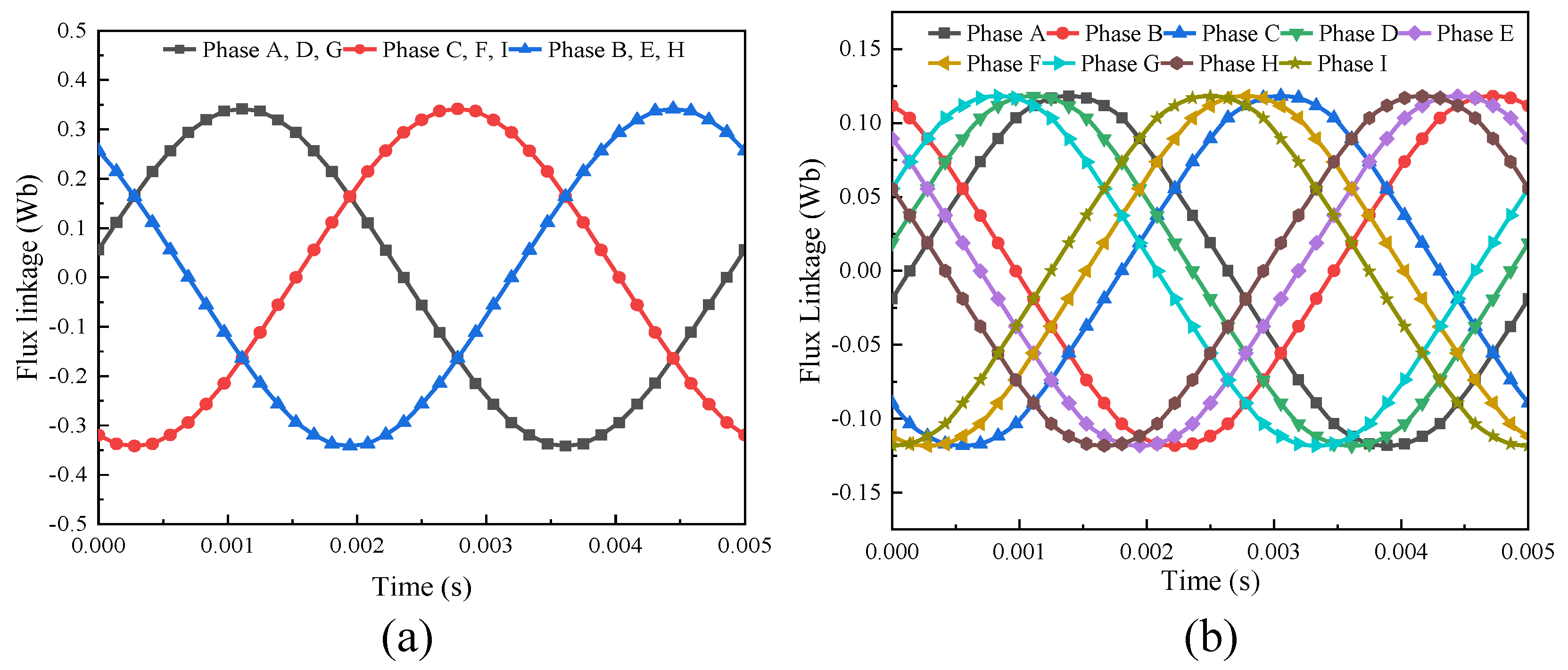
3.2. Comparative Study with Three-Phase Configuration

3.2.1. Theoretical Analysis

The current of the nine-phase scheme illustrated in Figure 4a can be expressed by the following equation set:
i A = I a sin ( ω t + θ i ) i B = I a sin ( ω t + θ i + 2 π / 3 ) i C = I a sin ( ω t + θ i 2 π / 3 ) i D = I a sin ( ω t + θ i + π / 9 ) i E = I a sin ( ω t + θ i + 7 π / 9 ) i F = I a sin ( ω t + θ i 5 π / 9 ) i G = I a sin ( ω t + θ i + 2 π / 9 ) i H = I a sin ( ω t + θ i + 8 π / 9 ) i I = I a sin ( ω t + θ i 4 π / 9 )
where i A to i I are the currents of each of the nine phases, ω is the rotating speed, and θ i is the initial current phase. The nine-phase coils are supplied by three sets of three-phase current sources. Coil phases A, B, and C are supplied by the first set of current sources; coil phases D, E, and F are supplied by the second set of current sources with 20 electrical degrees leading the first set; and coils phase G, H, and I are supplied by the third current source with 40 electrical degrees leading the first set. The harmonic components of the magnetic motive force (MMF) of the nine-phase coils are:
f A n = F φ n · cos n θ · cos ω t f B n = F φ n · cos n θ + 2 π / 3 · cos ( ω t + 2 π / 3 ) f C n = F φ n · cos n θ 2 π / 3 · cos ( ω t 2 π / 3 ) f D n = F φ n · cos n θ + π / 9 · cos ( ω t + π / 9 ) f E n = F φ n · cos n θ + 7 π / 9 · cos ( ω t + 7 π / 9 ) f F n = F φ n · cos n θ 5 π / 9 · cos ( ω t 5 π / 9 ) f G n = F φ n · cos n θ + 2 π / 9 · cos ( ω t + 2 π / 9 ) f H n = F φ n · cos n θ + 8 π / 9 · cos ( ω t + 8 π / 9 ) f I n = F φ n · cos n θ 4 π / 9 · cos ( ω t 4 π / 9 )
where f A n to f I n are the harmonics of the MMF of the nine-phase coil, and F φ n is the amplitude of the nth-order harmonic of the MMF of each phase coil, which can be expressed as:
F φ n = 0.9 N · K d p n · I r m s / n p
where N is the series turn number of each phase coil, K d p n is the winding factor of the nth order harmonic, I r m s is the rms value of the phase current, and p is the number of pole pairs. The total nth-order MMF harmonic is then the sum of f A n to f I n :
f n θ , t = f A n + f B n + f C n + f D n + f E n + f F n + f G n + f H n + f I n = F φ n 2 δ [ cos α + δ + cos β + δ ] = 0 ,   ± 2 ( n 1 ) π / 3 , ( n 1 ) π / 9 , 7 ( n 1 ) π / 9   , 5 ( n 1 ) π / 9 , 2 ( n 1 ) π / 9 , 8 ( n 1 ) π / 9 , 4 ( n 1 ) π / 9 } α = n θ ω t β = n θ + ω t
Subsequently, Equation (5) can be further simplified as:
f n θ , t = 0 , f o r   n = 6 k ± 1   o r   n = 3 j ,   k 1 ,   3 ,   5 ,   , j 1,2 ,   3 ,   m / 2 · F φ n · cos ω t n θ ,   f o r   n = 12 j ± 1 , j 1 ,   2 ,   3 ,  
where m is the phase number, which is equal to 9 in this case. According to Equation (9), it can be concluded that for multiple-of-third and third orders, where n = 3 j , when there is no path for the zero-sequence current to flow, the MMF harmonic does not exist. This is the same as in the conventional three-phase scheme. However, for n = 6 k ± 1 , the calculation result of f n θ , t is also 0; this implies that the nine-phase scheme produces no harmonics with orders of five, seven, seventeen, nineteen, etc., which makes it preferrable to the three-phase scheme. Next, the effect of the nine-phase scheme on the electromagnetic performance of the proposed machine is verified by the FEA, as described in the following subsections.

3.2.2. No-Load Analysis

Under no-load conditions, an FEA comparative analysis of the proposed FA-SynRM was carried out using two different winding schemes: a conventional three-phase scheme; and a nine-phase scheme with 20° electrical displacement between each set of three-phase windings. Both schemes were based on the proposed skewed slot design. The corresponding phasor diagrams for the two winding schemes are depicted in Figure 4. For the three-phase scheme (Figure 4b), windings with the same phase angle were connected in series.
Figure 15a,b show the flux linkage waveforms for the three-phase and nine-phase winding schemes under no-load conditions. It is evident that both schemes produce nearly identical sinusoidal flux linkage waveforms across all phases, with no visible differences in shape or amplitude. This similarity is expected, as the flux linkage under no-load conditions is primarily determined by the machine design and the rotor magnet configuration, rather than the specific winding scheme or supply type. The spectrum of the flux linkage is shown in Figure 16. To make a fair comparison, the amplitudes of the harmonic of the three-phase scheme are divided by three as each phase of the three-phase winding is composed of three phases of the nine-phase windings. The result indicates that the nine-phase scheme poses relatively higher amplitude in all harmonics including the fundamental one. This may be because the flux linkage waveform of each phase of the three-phase scheme can be regarded as a vector sum of each three corresponding waveforms in the nine-phase scheme; because there is a phase shift between them, the amplitude of all harmonic components including the fundamental is reduced.
The back-EMF waveforms for both winding schemes are shown in Figure 17. In the three-phase scheme, the waveform is sinusoidal, with each phase exhibiting amplitudes approximately three times larger than those observed in the nine-phase scheme. In contrast, the nine-phase scheme exhibits smaller back-EMF amplitudes but introduces more harmonic content, resulting in a less sinusoidal waveform. The FFT spectra of the standardized back-EMF for both schemes are compared in Figure 18. As with the result of the flux linkage, the nine-phase scheme shows an increased fundamental amplitude, and the harmonics at specific orders, such as the 3rd, 5th, and 7th (600 Hz, 1000 Hz, and 1400 Hz), are more prominent compared to the three-phase scheme. The THD for the three-phase scheme is 4.59%, which is lower than the 7.90% calculated for the nine-phase scheme.

3.2.3. On-Load Analysis

The on-load torque performance of the proposed FA-SynRM under three-phase and nine-phase winding schemes is compared across rotor initial mechanical angles ranging from −90- to 90°, as shown in Figure 19.
The average electromagnetic torque curves shown in Figure 19a exhibit similar shapes in the two schemes, with shifts of approximately 10° between their peaks. The nine-phase scheme achieves its maximum torque at −70°, while the three-phase scheme reaches its maximum at −80°. Additionally, the maximum average torque of the nine-phase scheme is slightly higher than that of the three-phase scheme. The torque ripple characteristics, shown in Figure 19b, indicate that the nine-phase scheme generally achieves lower ripple values; though values sometimes exceed 20%, they remain consistently below 30%. In contrast, the three-phase scheme demonstrates higher ripple values, with several exceeding 40% at specific rotor angles.
The time-domain waveform of the respective maximum torque is shown in Figure 20a. It is evident that the proposed nine-phase scheme achieves a higher average torque with a significantly lower torque ripple. This is further confirmed by the FFT analysis in Figure 20b, where the nine-phase scheme demonstrates a higher fundamental amplitude with nearly negligible harmonic components. In contrast, the conventional three-phase scheme exhibits a prominent 6th-order harmonic at 1200 Hz.

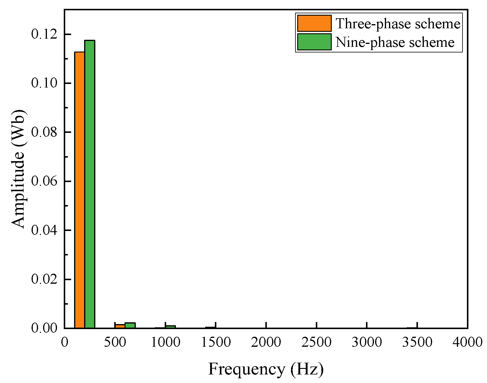
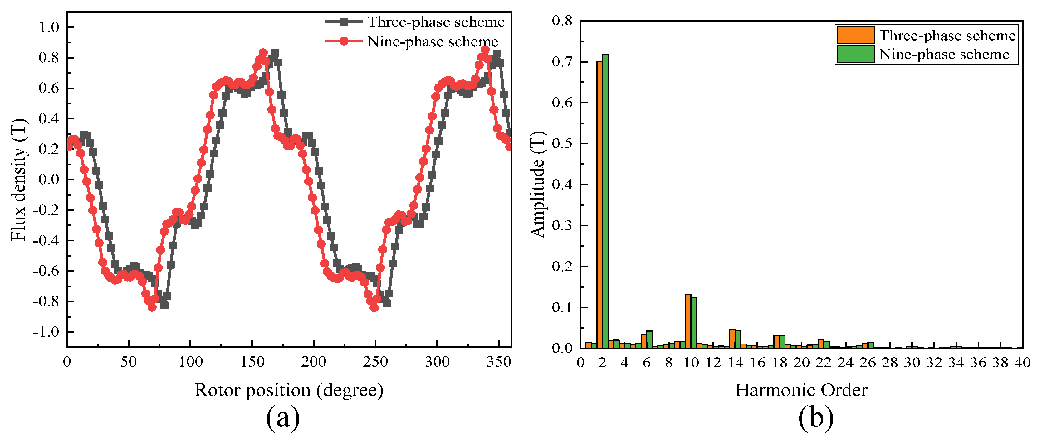
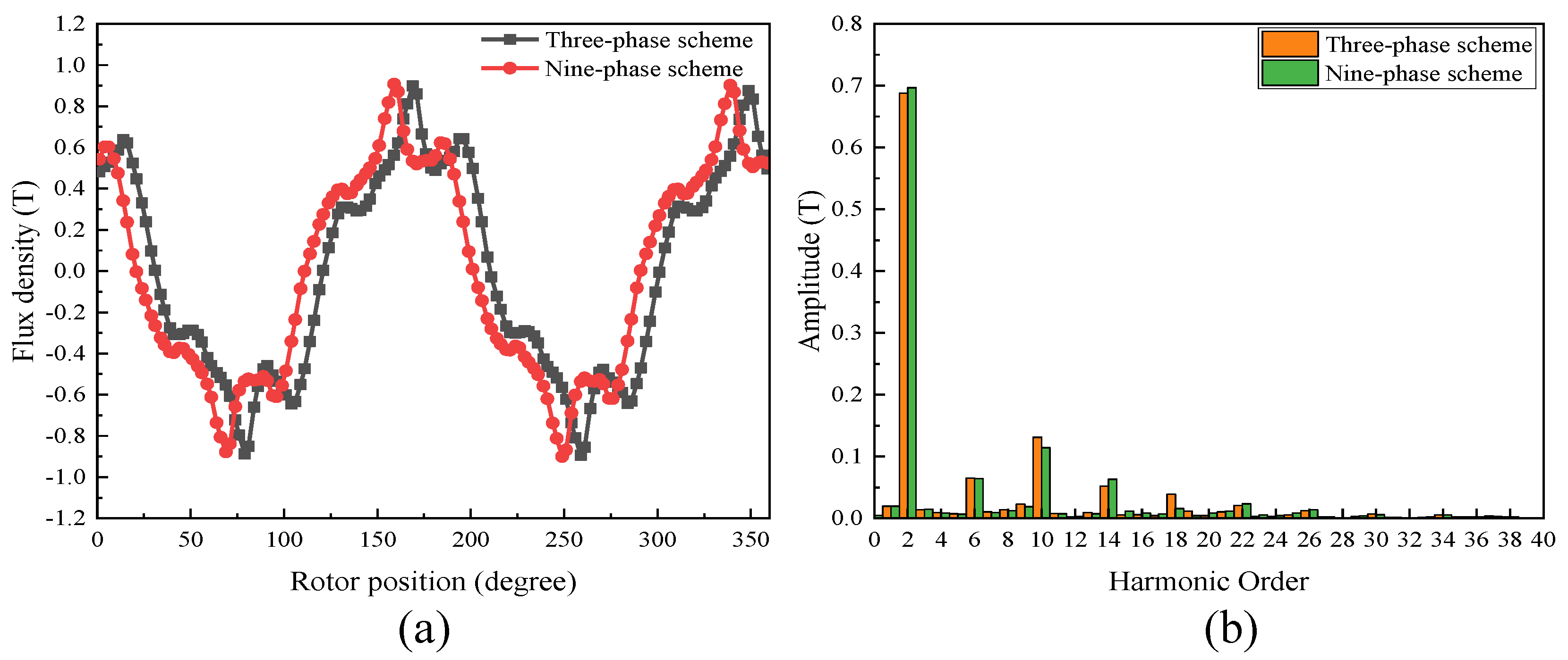
3.2.4. Air-Gap Flux Analysis

The air-gap flux density is analyzed in this section. The waveform of the flux density along the circumferential direction when excited solely by the armature winding is shown in Figure 21a. Apart from a phase shift caused by the skewed slot, the amplitudes of the three-phase and nine-phase schemes show no significant difference.
The FFT analysis in Figure 21b reveals that the nine-phase scheme outperforms the conventional three-phase design in terms of harmonic performance. It exhibits a slightly higher fundamental harmonic amplitude (second order) while suppressing higher-order unwanted harmonics. This cleaner harmonic profile contributes to smoother torque production, reduced losses, and lower vibration and noise, highlighting the advantages of the nine-phase configuration.
When rotor PMs are also considered, the corresponding flux density results are shown in Figure 22a. The flux density waveforms for both schemes exhibit a similar relationship to those in Figure 21a. The FFT analysis in Figure 22b further demonstrates that, except for the 14th harmonic, the nine-phase scheme maintains lower amplitudes across the most obvious harmonics, emphasizing its superior harmonic suppression capability.

4. Experimental Verification

Figure 23 illustrates the experimental test platform for the proposed FA-SynRM, which included the motor prototype and a digital bridge for testing. The primary objective of this experiment was to verify the phase inductance characteristics of the motor. A digital bridge was utilized to measure the inductive reactance of the windings at different rotor positions. The measured reactance data were then converted into inductance values. These experimental results were compared with FEA results to validate the accuracy and reliability of the proposed FA-SynRM design.
Figure 24a shows that the measured inductance of the nine-phase coils exhibits a high degree of consistency. Figure 24b shows the inductance of coil phase A measured in the FEA software. Compared with the experiment waveform, both of the phase inductances vary periodically with the rotor position, exhibiting a nearly sinusoidal waveform with high consistency in the shape of the waveform; however, the experimental waveform has a smaller variation range, with a relatively smaller maximum value and a larger minimum value, which may due to manufacturing tolerances and temperature effects.
Figure 25 compares the back-EMF waveforms from experimental measurements and FEA simulations. Due to the oscilloscope’s four-channel limit, measurements were conducted in three tests at rotation speed of 161 r/min to capture all nine phases. Both results show a consistent waveform shape, phase shift, and frequency, validating the machine design. Minor discrepancies in amplitude and smoothness in the experimental data may stem from unexpected losses, manufacturing tolerances, and other external interferences. Despite these differences, the strong correlation confirms the accuracy of the machine model and the reliability of the FEA predictions.

5. Conclusions

For this study, we proposed a novel nine-phase FA-SynRM design, incorporating ferrite magnets and a skewed stator slot structure, to address key challenges in electric machine performance. The proposed design was comprehensively analyzed and found to demonstrate significant improvements which were verified through FEA and experimental validation.
(1)
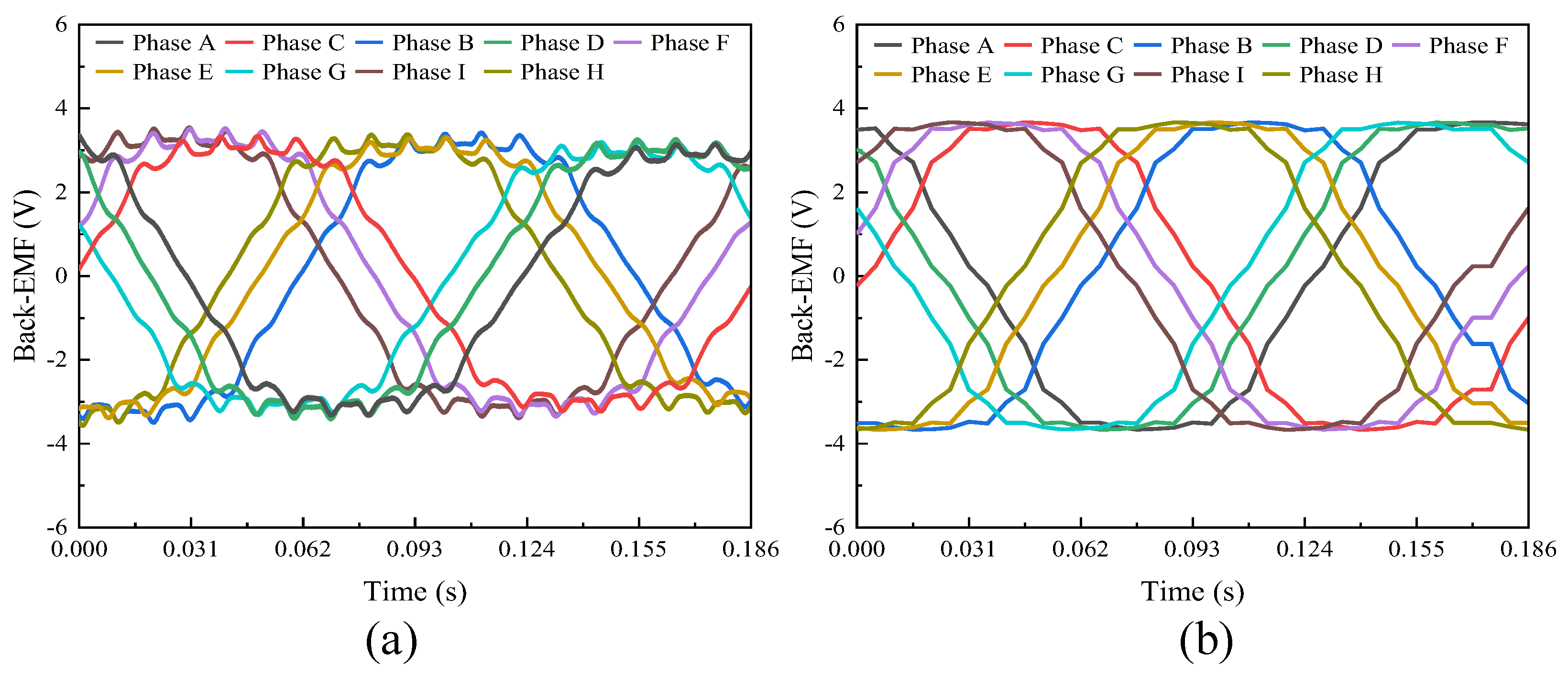
A 3D FEA model of the proposed FA-SynRM was established and compared with a reference FA-SynRM featuring non-skewed stator slots. The results revealed that the proposed design effectively suppressed harmonic components in the back-EMF, achieving a reduction in total harmonic distortion from 12.29% to 7.9%. Furthermore, at maximum on-load electromagnetic torque, the proposed design maintained a minimal torque ripple of 0.85%, significantly lower than the 28.27% observed in the non-skewed stator design. Additionally, the proposed machine exhibited lower stator losses, enhancing overall efficiency.
(2)
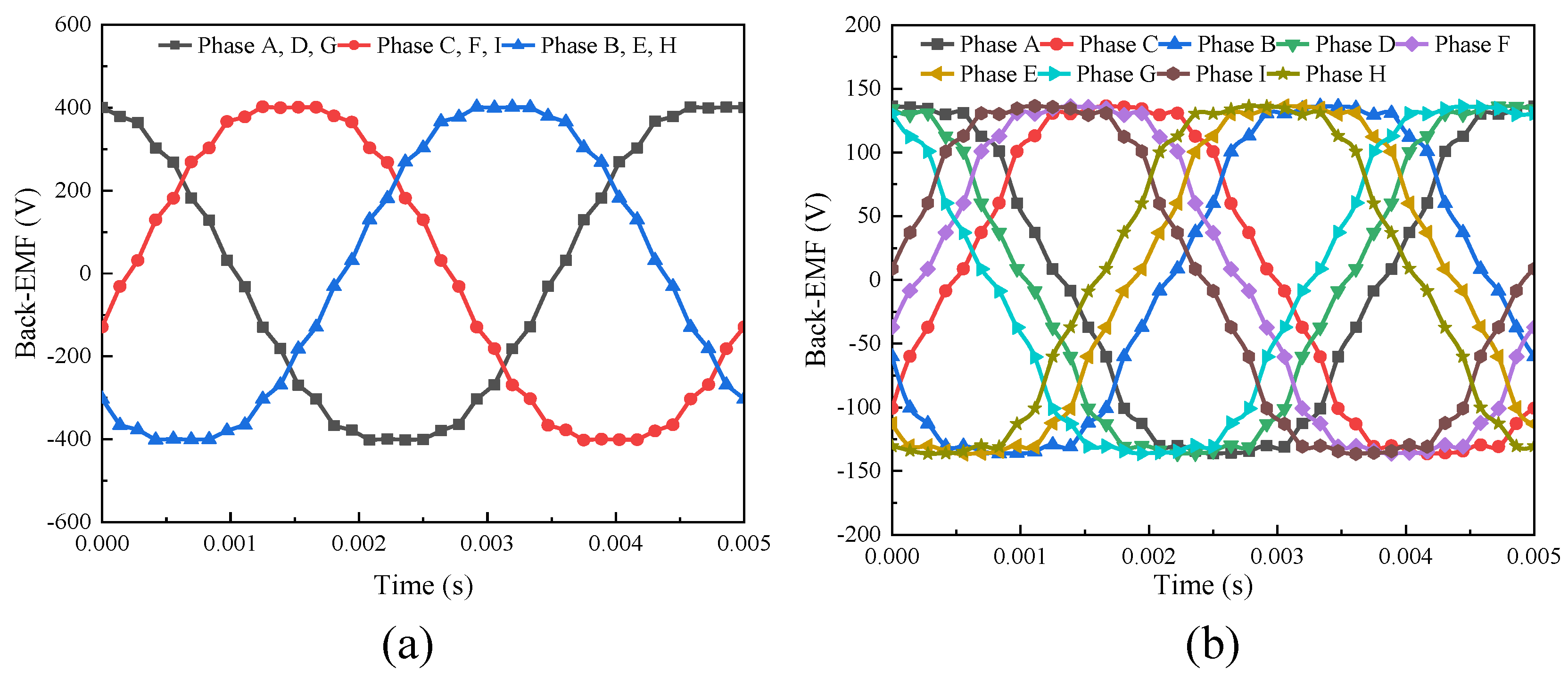
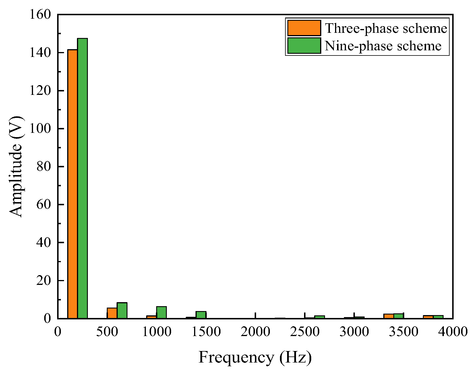
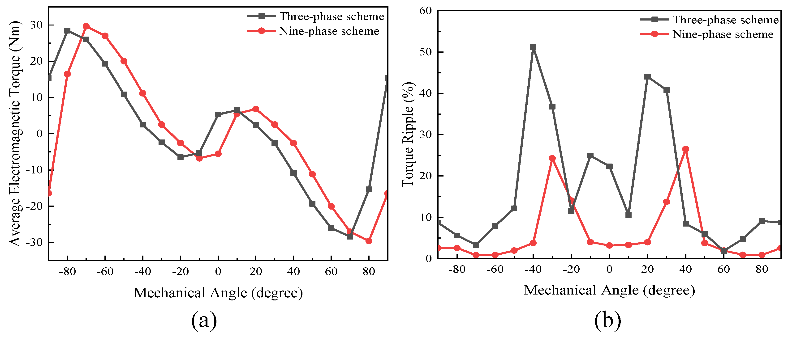
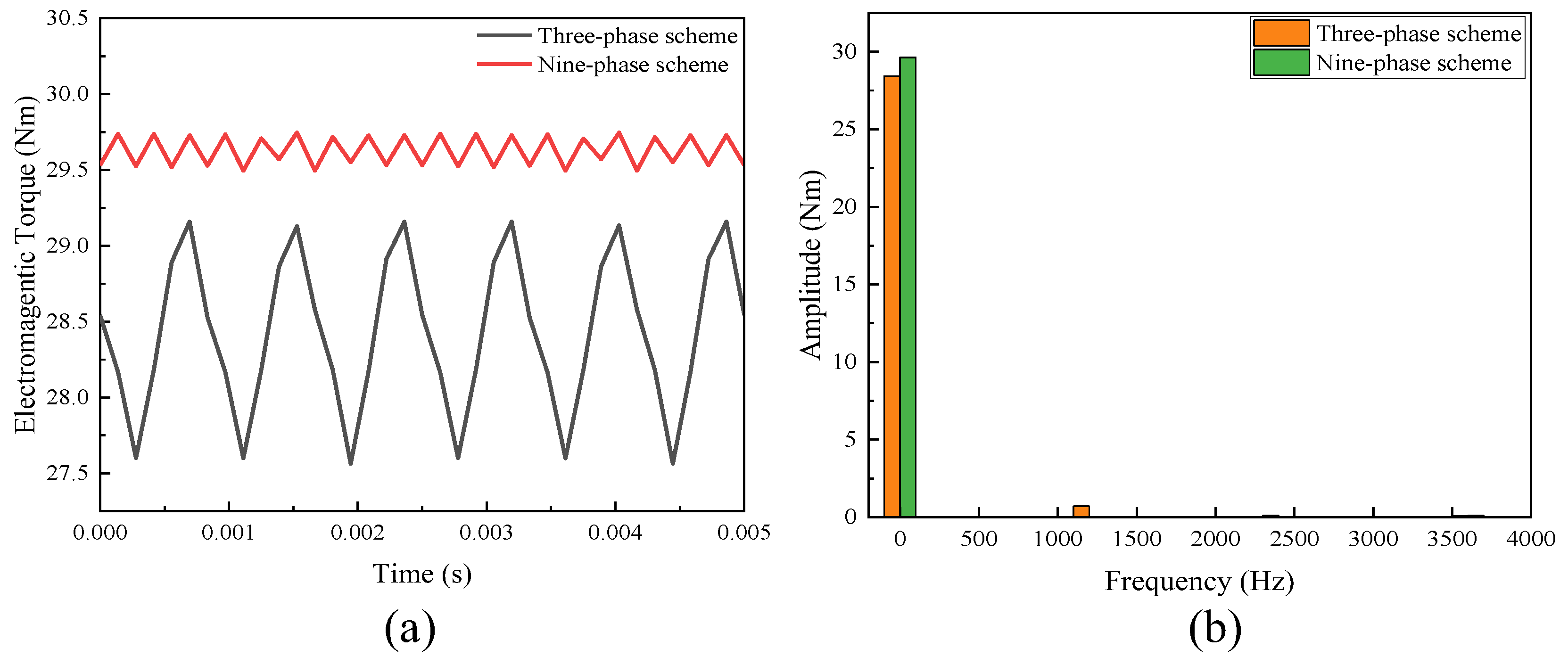
The performance of the proposed FA-SynRM was evaluated under both a nine-phase winding scheme and a traditional three-phase winding scheme. The nine-phase configuration demonstrated superior performance, achieving higher average torque with lower ripple. It also produced a higher fundamental harmonic amplitude in the air-gap flux density while suppressing unwanted harmonics.
(3)
A prototype of the proposed FA-SynRM was constructed, and experimental results were consistent with the FEA predictions, validating the effectiveness of the proposed design.

Author Contributions

Conceptualization, C.L., Z.S. and T.W.; methodology, H.G.; software, H.G.; validation, H.G. and H.C.; formal analysis, H.G.; investigation, H.G. and H.C.; resources, Z.S. and T.W.; data curation, H.G.; writing—original draft preparation, H.G.; writing—review and editing, T.W. and C.L.; visualization, H.G.; supervision, C.L.; project administration, C.L.; funding acquisition, C.L. All authors have read and agreed to the published version of the manuscript.

Funding

This work was supported in part by a grant by a grant (Project No. JCYJ20210324134005015) from the Science Technology and Innovation Committee of Shenzhen Municipality, Shenzhen, China; in part by a grant (Project No.: 9610673) from APRC of City University of Hong Kong, Hong Kong SAR; in part by a grant (Project No.: 7030020) from Booster Fund of City University of Hong Kong, Hong Kong SAR; and in part by RGC Research Fellow Scheme (RGC Ref. No.: RFS2223-1S05) from Research Grants Council, Hong Kong SAR.

Institutional Review Board Statement

Not applicable.

Informed Consent Statement

Not applicable.

Data Availability Statement

Data are contained within the article.

Conflicts of Interest

The authors declare no conflicts of interest.

References

  1. Cao, W.; Mecrow, B.C.; Atkinson, G.J.; Bennett, J.W.; Atkinson, D.J. Overview of Electric Motor Technologies Used for More Electric Aircraft (MEA). IEEE Trans. Ind. Electron. 2012, 59, 3523–3531. [Google Scholar] [CrossRef]
  2. Moghaddam, R.R.; Magnussen, F.; Sadarangani, C. Theoretical and Experimental Reevaluation of Synchronous Reluctance Machine. IEEE Trans. Ind. Electron. 2010, 57, 6–13. [Google Scholar] [CrossRef]
  3. Ajamloo, A.M.; Ghaheri, A.; Ibrahim, M.N.; Sergeant, P. Principle of Torque-Axis Alignment in New Asymmetric PM Synchronous Reluctance Machines: Toward Less-Rare-Earth PM Machines. IEEE Trans. Transp. Electrif. 2025, 11, 6392–6405. [Google Scholar] [CrossRef]
  4. Wang, T.; Wen, H.; Chen, Y.; Liu, C. A Novel Series Elastic Actuator with Variable Transmission Ratio Using Reconfigurable Epicyclic Gearing for Hip Exoskeletons. IEEE Trans. Ind. Electron. 2024, 72, 1–13. [Google Scholar] [CrossRef]
  5. Huang, R.; Dong, Z.; Song, Z.; Liu, C. A Novel Counter-Rotating AFPM Machine Based on Magnetic-Field Modulation for Underwater Propulsion System. IEEE Trans. Ind. Electron. 2024, 71, 2167–2176. [Google Scholar] [CrossRef]
  6. Nasiri-Zarandi, R.; Karami-Shahnani, A.; Toulabi, M.S.; Tessarolo, A. Design and Experimental Performance Assessment of an Outer Rotor PM-Assisted SynRM for the Electric Bike Propulsion. IEEE Trans. Transp. Electrif. 2023, 9, 727–736. [Google Scholar] [CrossRef]
  7. Levi, E. Multiphase Electric Machines for Variable-Speed Applications. IEEE Trans. Ind. Electron. 2008, 55, 1893–1909. [Google Scholar] [CrossRef]
  8. Barrero, F.; Duran, M.J. Recent Advances in the Design, Modeling, and Control of Multiphase Machines—Part I. IEEE Trans. Ind. Electron. 2016, 63, 449–458. [Google Scholar] [CrossRef]
  9. Duran, M.J.; Barrero, F. Recent Advances in the Design, Modeling, and Control of Multiphase Machines—Part II. IEEE Trans. Ind. Electron. 2016, 63, 459–468. [Google Scholar] [CrossRef]
  10. Huang, R.; Zhang, B.; Liu, Y.; Liu, C. Investigation of Magnetic Isolation in a Double-Side Asynchronous Rotor-AFPM Machine Based on Harmonic Analysis. IEEE Trans. Ind. Electron. 2025, 72, 240–250. [Google Scholar] [CrossRef]
  11. Islam, M.S.; Shrestha, A.; Halfmann, B.; Islam, M. Performance Evaluation of Permanent Magnet-Assisted Synchronous Reluctance Machines Under Faults for Redundant Applications. IEEE Trans. Transp. Electrif. 2024, 10, 10288–10296. [Google Scholar] [CrossRef]
  12. Boldea, I.; Tutelea, L.N.; Parsa, L.; Dorrell, D. Automotive Electric Propulsion Systems with Reduced or No Permanent Magnets: An Overview. IEEE Trans. Ind. Electron. 2014, 61, 5696–5711. [Google Scholar] [CrossRef]
  13. Trancho, E.; Ibarra, E.; Arias, A.; Kortabarria, I.; Jurgens, J.; Marengo, L.; Fricassè, A.; Gragger, J.V. PM-Assisted Synchronous Reluctance Machine Flux Weakening Control for EV and HEV Applications. IEEE Trans. Ind. Electron. 2018, 65, 2986–2995. [Google Scholar] [CrossRef]
  14. Boazzo, B.; Vagati, A.; Pellegrino, G.; Armando, E.; Guglielmi, P. Multipolar Ferrite-Assisted Synchronous Reluctance Machines: A General Design Approach. IEEE Trans. Ind. Electron. 2015, 62, 832–845. [Google Scholar] [CrossRef]
  15. Cai, H.; Guan, B.; Xu, L. Low-Cost Ferrite PM-Assisted Synchronous Reluctance Machine for Electric Vehicles. IEEE Trans. Ind. Electron. 2014, 61, 5741–5748. [Google Scholar] [CrossRef]
  16. Huang, R.; Liu, C. Improved PWM Control with Wide Speed Range for a Double-Side Asynchronous Rotor AFPMM Series-End Winding Drive. IEEE Trans. Power Electron. 2025, 40, 1728–1738. [Google Scholar] [CrossRef]
  17. Zhang, B.; Dong, Z.; Huang, R.; Liu, C. Reconfigurable Open-End Winding Motor Drive Topology for Inverter Short-Circuit Fault Tolerance. IEEE Trans. Power Electron. 2025, 40, 3854–3860. [Google Scholar] [CrossRef]
  18. Metwly, M.Y.; Abdel-Khalik, A.S.; Hamad, M.S.; Ahmed, S.; Elmalhy, N.A. Multiphase Stator Winding: New Perspectives, Advanced Topologies, and Futuristic Applications. IEEE Access 2022, 10, 103241–103263. [Google Scholar] [CrossRef]
  19. Tawfiq, K.B.; Güleç, M.; Sergeant, P.; Zeineldin, H.; Ibrahim, M.N.; Al-Durra, A.; El-Saadany, E.F. A Comprehensive Study of Thermal and Performance Characteristics in Revamped Multiphase Synchronous Reluctance Machines. IEEE Trans. Transp. Electrif. 2025, 11, 4717–4729. [Google Scholar] [CrossRef]
  20. Wang, P.; Gong, S.; Sun, X.; Liu, Z.; Jiang, D.; Qu, R. Fault-Tolerant Reconfiguration Topology and Control Strategy for Symmetric Open-Winding Multiphase Machines. IEEE Trans. Ind. Electron. 2022, 69, 8656–8666. [Google Scholar] [CrossRef]
  21. Tavares, R.B.; Goltz, E.C.; Eckert, P.R.; Pereira, L.A. Torque Assessment of Multiphase AFPM Machines with Experimental Validation for YASA Topology. IEEE Trans. Energy Convers. 2023, 38, 111–121. [Google Scholar] [CrossRef]
  22. Zhang, Z. Design and Performance Comparison of Nine-Phase Ferrite Spoke Interior Permanent Magnet Machines with Concentrated Windings for Traction Applications. In Proceedings of the 2021 IEEE Energy Conversion Congress and Exposition (ECCE), Vancouver, BC, Canada, 10–14 October 2021; pp. 4282–4288. [Google Scholar]
  23. Liu, Y.; Wang, W.; Liu, S.; Liu, C. A Compact Wireless Permanent Magnet Synchronous Motor System with Precise Speed and Position Control. IEEE Trans. Ind. Electron. 2024, 71, 11852–11863. [Google Scholar] [CrossRef]
  24. Wang, H.; Chau, K.T.; Liu, W.; Goetz, S.M. Design and Control of Wireless Permanent-Magnet Brushless DC Motors. IEEE Trans. Energy Convers. 2023, 38, 2969–2979. [Google Scholar] [CrossRef]
  25. Sui, Y.; Yin, Z.; Cheng, L.; Zheng, P.; Tang, D.; Chen, C.; Wang, C. Multiphase Modular Fault-Tolerant Permanent-Magnet Machine with Hybrid Single/Double-Layer Fractional-Slot Concentrated Winding. IEEE Trans. Magn. 2019, 55, 7500506. [Google Scholar] [CrossRef]
  26. Tawfiq, K.B.; Abdel-Khalik, A.S.; Ibrahim, M.N.; Refaie, A.M.E.; Sergeant, P. A Rewound Five-Phase Synchronous Reluctance Machine: Operating Voltage, Inductance Analysis and Comparison with Conventional Multiphase Machines. IEEE Trans. Ind. Appl. 2024, 60, 12–27. [Google Scholar] [CrossRef]
  27. Yang, H.Y.; Lim, Y.C.; Kim, H.C. Acoustic Noise/Vibration Reduction of a Single-Phase SRM Using Skewed Stator and Rotor. IEEE Trans. Ind. Electron. 2013, 60, 4292–4300. [Google Scholar] [CrossRef]
  28. Gan, C.; Wu, J.; Shen, M.; Yang, S.; Hu, Y.; Cao, W. Investigation of Skewing Effects on the Vibration Reduction of Three-Phase Switched Reluctance Motors. IEEE Trans. Magn. 2015, 51, 8203509. [Google Scholar] [CrossRef]
  29. Dhulipati, H.; Mukundan, S.; Iyer, K.L.V.; Kar, N.C. Skewing of stator windings for reduction of spatial harmonics in concentrated wound PMSM. In Proceedings of the 2017 IEEE 30th Canadian Conference on Electrical and Computer Engineering (CCECE), Windsor, ON, Canada, 30 April–3 May 2017; pp. 1–4. [Google Scholar]
  30. Diao, C.; Zhao, W.; Liu, Y.; Wang, X. Permanent Magnet Assisted Synchronous Reluctance Motor with Asymmetric Rotor for High Torque Performance. CES Trans. Electr. Mach. Syst. 2023, 7, 179–186. [Google Scholar] [CrossRef]
  31. Zhao, W.; Chen, D.; Lipo, T.A.; Kwon, B.I. Performance Improvement of Ferrite-Assisted Synchronous Reluctance Machines Using Asymmetrical Rotor Configurations. IEEE Trans. Magn. 2015, 51, 8108504. [Google Scholar] [CrossRef]
  32. Mohammadi, A.; Mirimani, S.M. Design of a Novel PM-Assisted Synchronous Reluctance Motor Topology Using V-Shape Permanent Magnets for Improvement of Torque Characteristic. IEEE Trans. Energy Convers. 2022, 37, 424–432. [Google Scholar] [CrossRef]
  33. Xie, Y.; Shao, J.; He, S.; Ye, B.; Yang, F.; Wang, L. Novel PM-Assisted Synchronous Reluctance Machines Using Asymmetrical Rotor Configuration. IEEE Access 2022, 10, 79564–79573. [Google Scholar] [CrossRef]
  34. Zhao, W.; Xing, F.; Wang, X.; Lipo, T.A.; Kwon, B.i. Design and Analysis of a Novel PM-Assisted Synchronous Reluctance Machine with Axially Integrated Magnets by the Finite-Element Method. IEEE Trans. Magn. 2017, 53, 8104104. [Google Scholar] [CrossRef]
  35. Bianchi, N.; Degano, M.; Fornasiero, E. Sensitivity Analysis of Torque Ripple Reduction of Synchronous Reluctance and Interior PM Motors. IEEE Trans. Ind. Appl. 2015, 51, 187–195. [Google Scholar] [CrossRef]
  36. Korman, O.; Nardo, M.D.; Degano, M.; Gerada, C. A Novel Flux Barrier Parametrization for Synchronous Reluctance Machines. IEEE Trans. Energy Convers. 2022, 37, 675–684. [Google Scholar] [CrossRef]
  37. Ooi, S.; Morimoto, S.; Sanada, M.; Inoue, Y. Performance Evaluation of a High-Power-Density PMASynRM with Ferrite Magnets. IEEE Trans. Ind. Appl. 2013, 49, 1308–1315. [Google Scholar] [CrossRef]
  38. Al-ani, M.; Walker, A.; Vakil, G.; Gerada, D.; Gerada, C.; Paciura, K. Modifications to PM-Assisted Synchronous Reluctance Machine to Achieve Rare-Earth Free Heavy-Duty Traction. IEEE J. Emerg. Sel. Top. Power Electron. 2023, 11, 2029–2038. [Google Scholar] [CrossRef]
  39. Barcaro, M.; Bianchi, N. Interior PM Machines Using Ferrite to Replace Rare-Earth Surface PM Machines. IEEE Trans. Ind. Appl. 2014, 50, 979–985. [Google Scholar] [CrossRef]
  40. Shen, J.X.; Lin, Y.Q.; Sun, Y.; Qin, X.F.; Wan, W.J.; Cai, S. Permanent Magnet Synchronous Reluctance Machines with Axially Combined Rotor Structure. IEEE Trans. Magn. 2022, 58, 8103310. [Google Scholar] [CrossRef]
Figure 1. Schematic diagram of wearable robotics.
Energies 18 02323 g001
Figure 2. Proposed FA-SynRM. (a) Exploded view; (b) cross-sectional view of the skewed stator.
Energies 18 02323 g002
Figure 3. Cross-section of the proposed nine-phase FA-SynRM with d-q-axis reference frame shown.
Energies 18 02323 g003
Figure 4. Winding configuration. (a) Nine-phase winding with 20 electrical degrees displacement; (b) three-phase winding.
Energies 18 02323 g004
Figure 5. Torque characteristics of FA-SynRM. (a) Torque waveform; (b) phasor diagram in the d-q reference frame.
Energies 18 02323 g005
Figure 6. Flux distribution of the FA-SynRM under rated conditions.
Energies 18 02323 g006
Figure 7. Waveforms of the no-load flux linkage of (a) the conventional FA-SynRM without skewed stator slot; (b) the proposed FA-SynRM.
Energies 18 02323 g007
Figure 8. Spectrum of the no-load flux linkage of the skewed and non-skewed stator designs.
Energies 18 02323 g008
Figure 9. Waveforms of the back-EMF of (a) the conventional FA-SynRM without skewed stator slot; (b) the proposed FA-SynRM.
Energies 18 02323 g009
Figure 10. Spectrum of the back-EMF of the skewed and non-skewed stator designs.
Energies 18 02323 g010
Figure 11. Waveform of the cogging torque.
Energies 18 02323 g011
Figure 12. Torque characteristics at different rotor initial positions. (a) Average torque; (b) torque ripple.
Energies 18 02323 g012
Figure 13. Comparison of the output electromagnetic torque between the skewed and non-skewed stator designs. (a) Waveform of the output torque; (b) spectrum of the output torque.
Energies 18 02323 g013
Figure 14. Loss analysis.
Energies 18 02323 g014
Figure 15. Waveforms of no-load flux linkage of the proposed FA-SynRM under (a) three-phase scheme; (b) nine-phase scheme.
Energies 18 02323 g015
Figure 16. Spectrum of the no-load flux linkage.
Energies 18 02323 g016
Figure 17. Waveforms of back-EMF of the proposed FA-SynRM under (a) three-phase scheme; (b) nine-phase scheme.
Energies 18 02323 g017
Figure 18. Spectrum of the back-EMF of the machine under two winding schemes.
Energies 18 02323 g018
Figure 19. Torque characteristics at different rotor initial positions. (a) Average electromagnetic torque; (b) torque ripple.
Energies 18 02323 g019
Figure 20. Comparison of the output electromagnetic torque of the machine under two winding schemes. (a) Waveform of the output torque; (b) spectrum of the output torque.
Energies 18 02323 g020
Figure 21. Airgap flux density analysis when excited only by armature winding. (a) Waveform; (b) spectrum.
Energies 18 02323 g021
Figure 22. Airgap flux density analysis when excited by rotor PMs and armature winding. (a) Waveform; (b) spectrum.
Energies 18 02323 g022
Figure 23. Prototype of the proposed FA-SynRM.
Energies 18 02323 g023
Figure 24. Phase inductance of the proposed FA-SynRM. (a) Experiment results; (b) FEA results.
Energies 18 02323 g024
Figure 25. Back-EMF of the proposed FA-SynRM. (a) Experiment results; (b) FEA results.
Energies 18 02323 g025
Table 1. Specification of the proposed FA-SynRM.
ParameterValue
Outer stator radius100 mm
Inner stator radius56.6 mm
Outer rotor radius56.1 mm
Inner rotor radius19 mm
Air-gap length0.5 mm
Axial length60 mm
Number of coil turns35
Rated current (rms)8 A
Rated speed6000 r/min
Ferrite remanence0.4 T
Disclaimer/Publisher’s Note: The statements, opinions and data contained in all publications are solely those of the individual author(s) and contributor(s) and not of MDPI and/or the editor(s). MDPI and/or the editor(s) disclaim responsibility for any injury to people or property resulting from any ideas, methods, instructions or products referred to in the content.

