


Open-Circuit Fault Mitigation for Inverter-Driven Induction Motor Based on Closed-Loop Volt-per-Hertz

Abstract
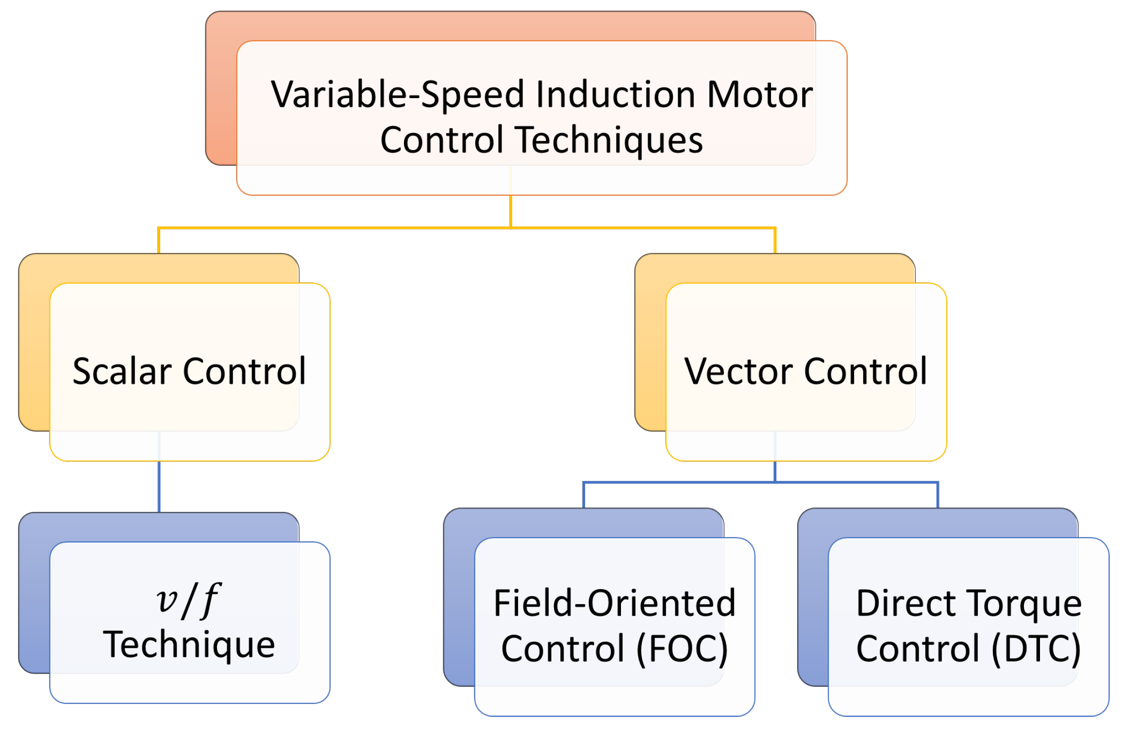
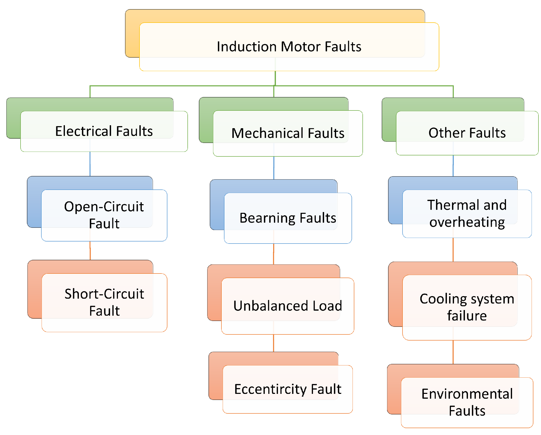
1. Introduction
- Demonstration of the limitations of open-loop V/f control under OCF conditions;
- The PR controller is analyzed to maintain continuous motor operation during fault and post-fault operation as the PI controller fails to achieve such performance;
- The PI control method fails to maintain continuous motor operation during the OCF due to the double sinusoidal term;
- A new novel controller using the PIR controller is introduced. The resonant controller (RC) is combined with a PI controller, resulting in a PIR controller, which makes the new modified controller work effectively under OCF conditions;
- The PIR control exhibits a better dynamic performance under OCF with minimal torque ripple compared to the PI and PR controller behaviors;
- Elimination of the need for fault detection systems, offering a simpler and cost-effective solution for OCF operation.
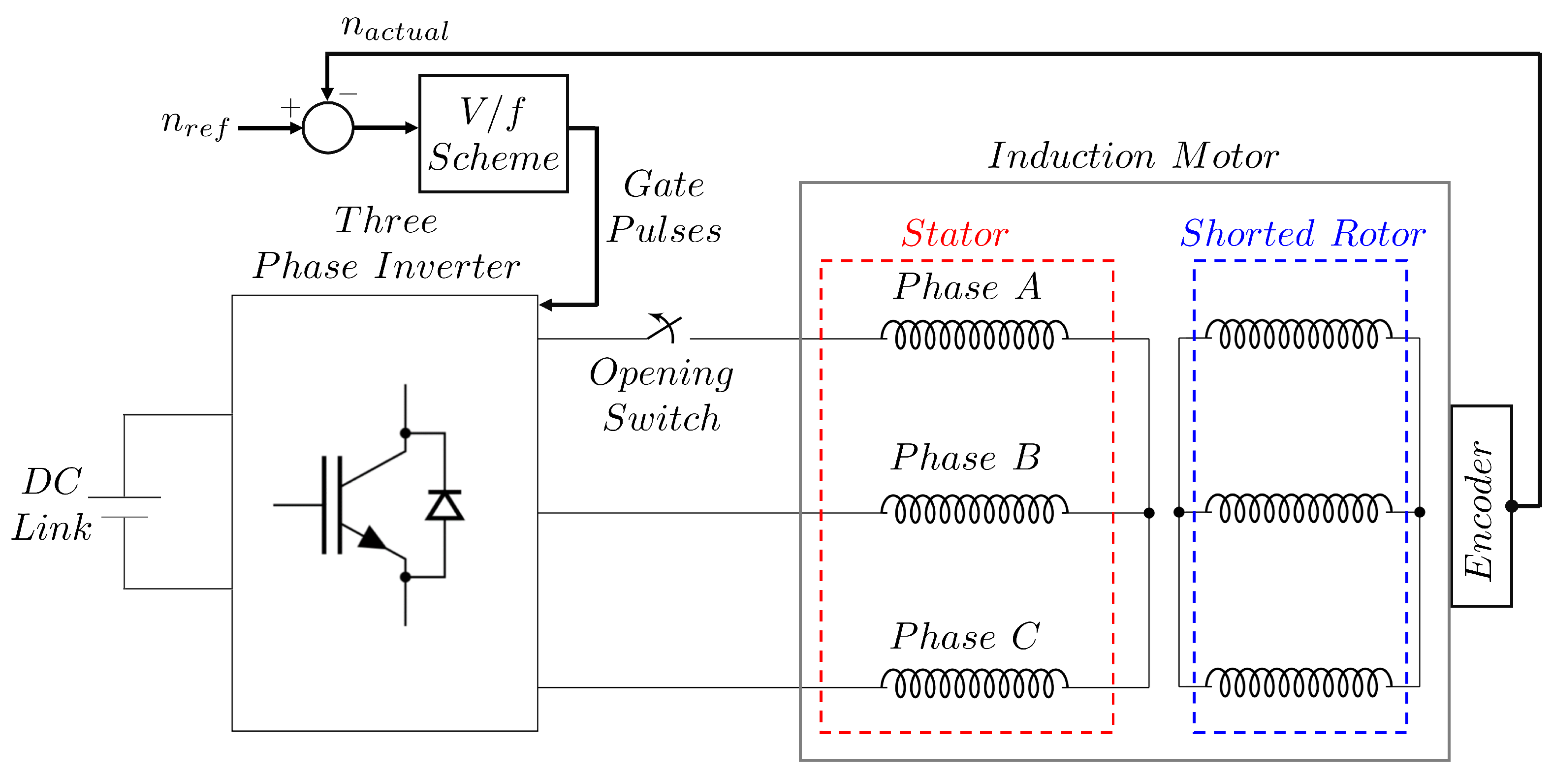
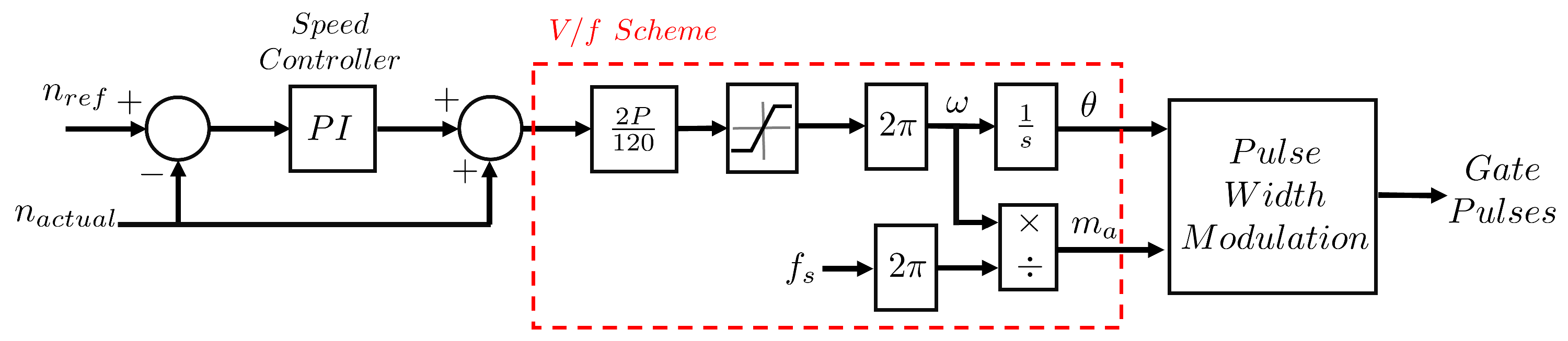
2. System Model Equations
3. Closed-Loop V/f Control Techniques Under OCF
3.1. Closed-Loop V/f Control Using PI Control Method
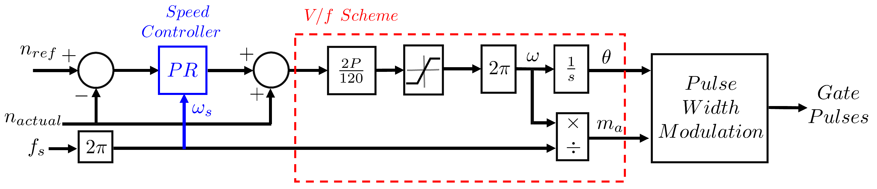
3.2. Closed-Loop V/f Control Using PR Control Method
- The proportional gain () is set to a small value to ensure system stability while minimizing overshoot in the system’s performance;
- The resonant gain () is tuned to enhance disturbance rejection and improve fault tolerance. However, excessive values may introduce system instability, so a balance must be maintained;
- The resonant frequency () is determined directly from the fundamental frequency of the motor currents under OCF conditions, ensuring accurate tuning. It is calculated aswhere P is the number of poles, is the desired reference speed in rpm, and is the frequency at the desired speed. This method ensures that is accurately synchronized with the motor dynamics without requiring iterative tuning techniques;
- The PR controller gains are selected through careful tuning, striking a balance between improved control performance and maintaining system stability, similar to classical tuning methodologies.
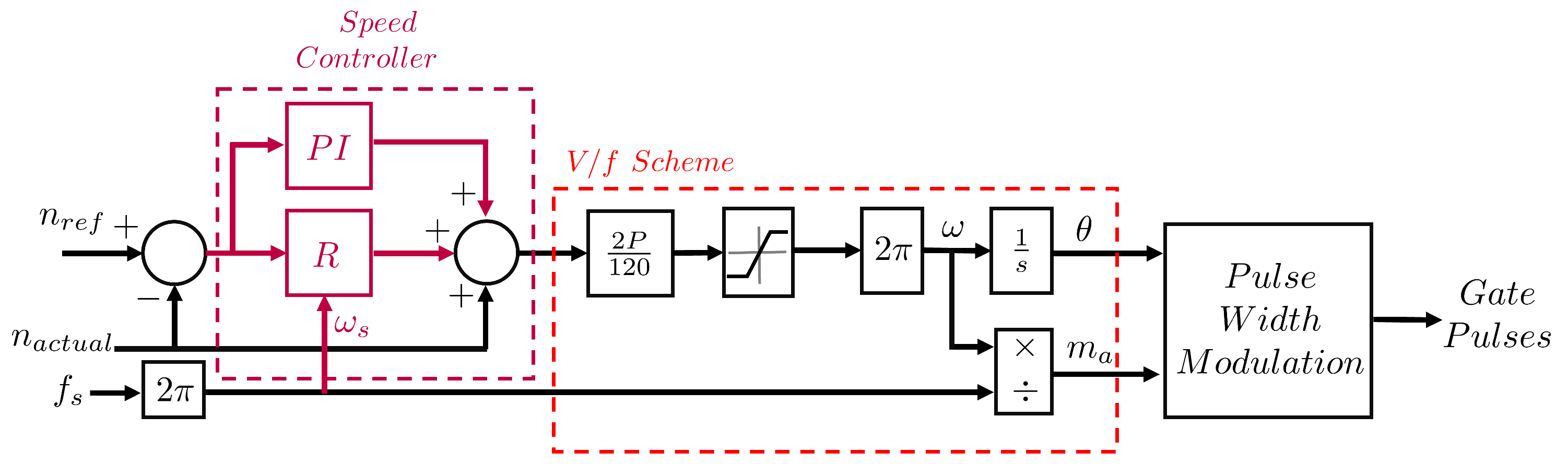
3.3. Closed-Loop V/f Control Using PIR Control Method
- The proportional gain () is set to a small value to ensure system stability while minimizing overshoot in the system’s performance. It can be tuned in the same manner as Z–N method;
- The integral gain () is tuned to balance steady-state error reduction and dynamic response. While increasing reduces steady-state error, excessive values may introduce overshoot and oscillations, so careful tuning is essential. It can be tuned in the same manner as Z–N method;
- The resonant gain () enhances disturbance rejection and improves performance under OCF conditions. However, excessive values may compromise system stability, necessitating a well-balanced selection. It can be tuned in the same manner as in the PR controller tunning method;
- The resonant frequency () is determined directly from the fundamental frequency of the motor currents under OCF conditions, which can be tuned in the same manner as in the PR controller tunning method. It is calculated aswhere P is the number of poles and is the desired reference speed in rpm. This ensures that is accurately synchronized with the motor dynamics without requiring iterative tuning techniques;
- The PIR controller gains are selected through careful tuning, ensuring an optimal balance between improved control performance and maintaining system stability, similar to classical tuning methodologies.
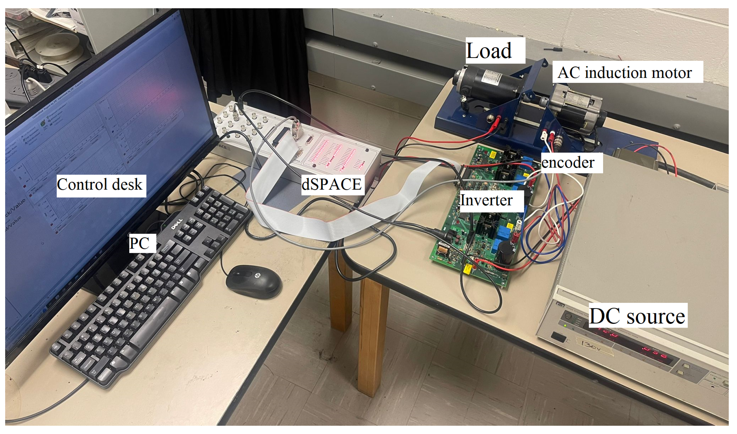
4. Experimental Case Studies
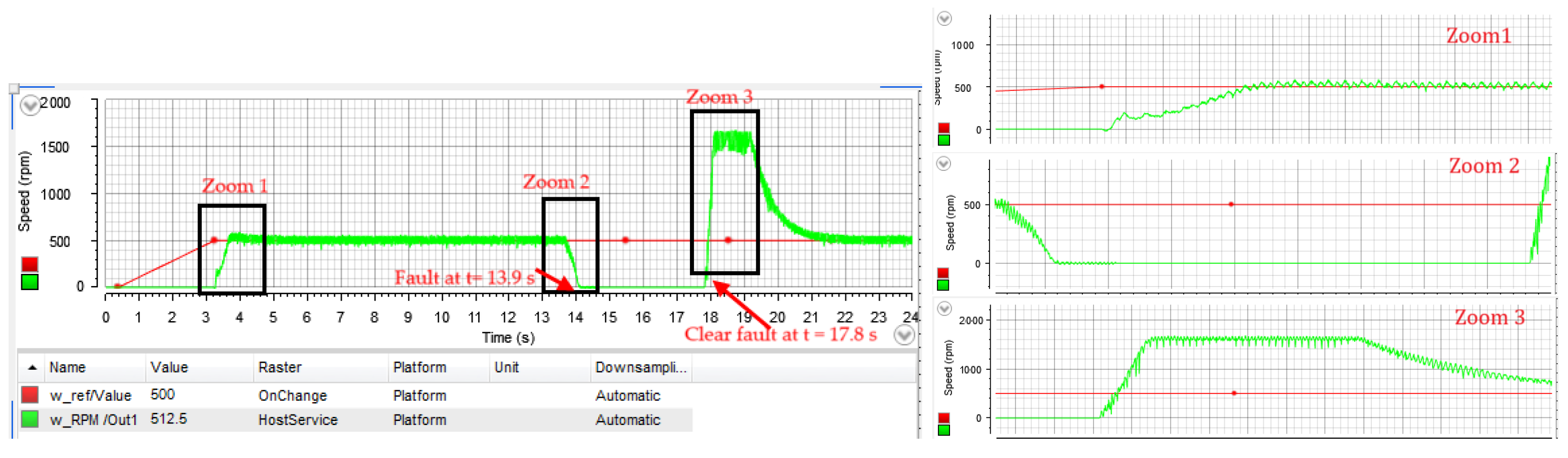
4.1. PI Case Study
4.2. PR Case Study
4.3. PIR Case Study
5. Conclusions
Author Contributions
Funding
Data Availability Statement
Conflicts of Interest
References
- Zahedi, B.; Vaez-Zadeh, S. Efficiency Optimization Control of Single-Phase Induction Motor Drives. IEEE Trans. Power Electron. 2009, 24, 1062–1070. [Google Scholar] [CrossRef]
- Jannati, M.; Anbaran, S.A.; Asgari, S.H.; Goh, W.Y.; Monadi, A.; Abdul, A.M.; Idris, N. A review on Variable Speed Control techniques for efficient control of Single-Phase Induction Motors: Evolution, classification, comparison. Renew. Sustain. Energy Rev. 2017, 27, 1306–1319. [Google Scholar]
- dos Santos, T.; Goedtel, A.; da Silva, S.; Suetake, M. Scalar control of an induction motor using a neural sensorless technique. Electr. Power Syst. Res. 2014, 108, 322–330. [Google Scholar]
- Hinkkanen, M.; Tiitinen, L.; Molsa, E.; Harnefors, L. On the Stability of Volts-per-Hertz Control for Induction Motors. IEEE J. Emerg. Sel. Top. Power Electron. 2022, 10, 1609–1618. [Google Scholar] [CrossRef]
- Shrawane, P. Induction motor open- and closed-loop control using Volt-per-Hertz controller. In Proceedings of the 12th IEEE International Power Electronics Congress, San Luis Potosi, Mexico, 22–25 August 2010; pp. 97–101. [Google Scholar] [CrossRef]
- Hegde, S.; Angadi, S.; Raju, A.B. Speed control of 3-phase induction motor using volt/hertz control for automotive application. In Proceedings of the 2016 International Conference on Circuits, Controls, Communications and Computing (I4C), Bangalore, India, 4–6 October 2016; pp. 1–5. [Google Scholar] [CrossRef]
- Li, W.; Xu, Z.; Zhang, Y. Induction motor control system based on FOC algorithm. In Proceedings of the 2019 IEEE 8th Joint International Information Technology and Artificial Intelligence Conference (ITAIC), Chongqing, China, 24–26 May 2019; pp. 1544–1548. [Google Scholar] [CrossRef]
- Mehammai, C.; Zidani, F.; Benaicha, S.; Nait-Said, M. Research on improvement of FOC system for induction motor using fuzzy logic. Int. J. Model. Identif. Control IJMIC 2014, 21, 370–377. [Google Scholar]
- Ba-Razzouk, A.; Cheriti, A.; Olivier, G.; Sicard, P. Field-oriented control of induction motors using neural-network decouplers. IEEE Trans. Power Electron. 1997, 12, 752–763. [Google Scholar] [CrossRef]
- Talla, J.; Kosan, T.; Blahnik, V. FOC-based Speed Control Algorithms of Induction Motor Drive with System Parameter Mismatch. In Proceedings of the 18th International Conference on Mechatronics—Mechatronika (ME), Brno, Czech Republic, 5–7 December 2018; pp. 1–8. [Google Scholar]
- Malla, S.G. A review on Direct Torque Control (DTC) of induction motor: With applications of fuzzy. In Proceedings of the International Conference on Electrical, Electronics, and Optimization Techniques (ICEEOT), Chennai, India, 3–5 March 2016; pp. 4557–4567. [Google Scholar] [CrossRef]
- Zaky, M.S. High performance DTC of induction motor drives over a wide speed range. Electr. Eng. 2015, 97, 139–154. [Google Scholar] [CrossRef]
- Gadoue, S.M.; Giaouris, D.; Finch, J.W. Artificial intelligence-based speed control of DTC induction motor drives—A comparative study. Electr. Power Syst. Res. 2009, 79, 210–219. [Google Scholar] [CrossRef]
- Lis, J.; Kowalski, C.T.; Orlowska-Kowalska, T. Sensorless DTC control of the induction motor using FPGA. In Proceedings of the IEEE International Symposium on Industrial Electronics, Cambridge, UK, 30 June–2 July 2008; pp. 1914–1919. [Google Scholar] [CrossRef]
- Le-Huy, H. Comparison of field-oriented control and direct torque control for induction motor drives. In Proceedings of the Conference Record of the 1999 IEEE Industry Applications Conference. Thirty-Forth IAS Annual Meeting, Phoenix, AZ, USA, 3–7 October 1999; pp. 1245–1252. [Google Scholar] [CrossRef]
- Suman, N.; Prasad, U.; Kumar, R. Comparison between Direct Torque Control based on Space Vector Modulation with Conventional Direct Torque Control Technique for Speed Control of Three-phase Induction Motor. In Proceedings of the Fourth International Conference on Advances in Electrical, Computing, Communication and Sustainable Technologies (ICAECT), Bhilai, India, 11–12 January 2024; pp. 1–6. [Google Scholar] [CrossRef]
- Gundewar, S.K.; Kane, P.V. Condition Monitoring and Fault Diagnosis of Induction Motor. J. Vib. Eng. Technol. 2021, 9, 643–674. [Google Scholar] [CrossRef]
- Ghanayem, H.; Alathamneh, M.; Nelms, R.M. Decoupled Speed and Flux Control of a Three-Phase Permanent Magnet Synchronous Motor under an Open-Circuit Fault Using a PR Current Controller. Energies 2023, 16, 5325. [Google Scholar] [CrossRef]
- Bazzi, A.M.; Ding, X.; Dominguez-García, A.; Krein, P.T. Circuit-based induction motor drive reliability under different control schemes and safe-mode operation. In Proceedings of the Twenty-Sixth Annual IEEE Applied Power Electronics Conference and Exposition (APEC), Fort Worth, TX, USA, 6–11 March 2011; pp. 653–660. [Google Scholar] [CrossRef]
- Liu, T.H.; Fu, J.R.; Lipo, T.A. A strategy for improving reliability of field-oriented controlled induction motor drives. IEEE Trans. Ind. Appl. 1993, 29, 910–918. [Google Scholar]
- Mohammadpour, A.; Sadeghi, S.; Parsa, L. A generalized fault-tolerant control strategy for five-phase PM motor drives considering star, pentagon, and pentacle connections of stator windings. IEEE Trans. Ind. Electron. 2014, 61, 63–75. [Google Scholar] [CrossRef]
- Jasim, O.; Sumner, M.; Gerada, C.; Arellano-Padilla, J. Development of a new fault-tolerant induction motor control strategy using an enhanced equivalent circuit model. IET Electr. Power Appl. 2011, 5, 618–627. [Google Scholar]
- Rangari, S.C.; Suryawanshi, H.M.; Renge, M. New Fault-Tolerant Control Strategy of Five-Phase Induction Motor with Four-Phase and Three-Phase Modes of Operation. Electronics 2018, 7, 159. [Google Scholar] [CrossRef]
- Guzman, H.; Duran, M.J.; Barrero, F.; Bogado, B.; Toral, S. Speed Control of Five-Phase Induction Motors With Integrated Open-Phase Fault Operation Using Model-Based Predictive Current Control Techniques. IEEE Trans. Ind. Electron. 2014, 61, 4474–4484. [Google Scholar]
- Bermudez, M.; Gonzalez-Prieto, I.; Barrero, F.; Guzman, H.; Duran, M.J.; Kestelyn, X. Open-Phase Fault-Tolerant Direct Torque Control Technique for Five-Phase Induction Motor Drives. IEEE Trans. Ind. Electron. 2017, 64, 902–911. [Google Scholar] [CrossRef]
- Dwari, S.; Parsa, L. Fault-Tolerant Control of Five-Phase Permanent-Magnet Motors With Trapezoidal Back EMF. IEEE Trans. Ind. Electron. 2011, 58, 476–485. [Google Scholar] [CrossRef]
- Tabbache, B.; Benbouzid, M.; Kheloui, A.; Bourgeot, J.; Mamoune, A. An improved fault-tolerant control scheme for PWM inverter-fed induction motor-based EVs. Isa Trans. 2013, 52, 862–869. [Google Scholar] [CrossRef]
- Khamis, A.; Owaj, A.; Abbas, A. Performance Improvement of a Conventional Direct Torque Control of a Three-Phase Induction Motor. Int. J. Eng. Inf. Technol. IJET 2020, 6, 65–72. [Google Scholar]
- Ziegler, J.G.; Nichols, N.B. Optimum Settings for Automatic Controllers. J. Dyn. Syst. Meas. Control 1993, 115, 220–222. [Google Scholar] [CrossRef]
- Ghanayem, H.; Alathamneh, M.; Nelms, R.M. PMSM Field-Oriented Control with Independent Speed and Flux Controllers for Continuous Operation under Open-Circuit Fault at Light Load Conditions. Energies 2024, 17, 593. [Google Scholar] [CrossRef]

| Parameters | Value | Unit |
|---|---|---|
| Rated.Power | 120 | W |
| Rated.Volts | 30 | |
| Max.Speed | 4000 | RPM |
| Rated.Amps | 6 | |
| Resistance.(L-L) | 0.7 | Ohms |
| Inductance | 2.27 | mH |
Disclaimer/Publisher’s Note: The statements, opinions and data contained in all publications are solely those of the individual author(s) and contributor(s) and not of MDPI and/or the editor(s). MDPI and/or the editor(s) disclaim responsibility for any injury to people or property resulting from any ideas, methods, instructions or products referred to in the content. |
© 2025 by the authors. Licensee MDPI, Basel, Switzerland. This article is an open access article distributed under the terms and conditions of the Creative Commons Attribution (CC BY) license (https://creativecommons.org/licenses/by/4.0/).
Share and Cite
Alathamneh, M.; Ghanayem, H.; Nelms, R.M.; Allafi, I.M. Open-Circuit Fault Mitigation for Inverter-Driven Induction Motor Based on Closed-Loop Volt-per-Hertz. Energies 2025, 18, 1596. https://doi.org/10.3390/en18071596
Alathamneh M, Ghanayem H, Nelms RM, Allafi IM. Open-Circuit Fault Mitigation for Inverter-Driven Induction Motor Based on Closed-Loop Volt-per-Hertz. Energies. 2025; 18(7):1596. https://doi.org/10.3390/en18071596
Chicago/Turabian StyleAlathamneh, Mohammad, Haneen Ghanayem, R. M. Nelms, and Ibrahim M. Allafi. 2025. "Open-Circuit Fault Mitigation for Inverter-Driven Induction Motor Based on Closed-Loop Volt-per-Hertz" Energies 18, no. 7: 1596. https://doi.org/10.3390/en18071596
APA StyleAlathamneh, M., Ghanayem, H., Nelms, R. M., & Allafi, I. M. (2025). Open-Circuit Fault Mitigation for Inverter-Driven Induction Motor Based on Closed-Loop Volt-per-Hertz. Energies, 18(7), 1596. https://doi.org/10.3390/en18071596