Article

Towards Nonlinear Magnetic Rotating Pendula for Low-Frequency Weak Vibration Energy Harvesting

by
Mihai Ionut Trandafir
and
Panagiotis Alevras
*
School of Production Engineering and Management, Technical University of Crete, 73100 Chania, Greece
*
Author to whom correspondence should be addressed.
Energies 2025, 18(8), 2058; https://doi.org/10.3390/en18082058
Submission received: 3 April 2025 / Revised: 11 April 2025 / Accepted: 15 April 2025 / Published: 17 April 2025
(This article belongs to the Special Issue Advances in Energy Harvesting Systems)

Abstract

:
Energy harvesting from ambient vibrations has received significant attention as an alternative renewable, clean energy source for microelectronic devices in diverse applications such as wearables and environmental monitoring. However, typical vibrations in remote environments exhibit ultra-low frequencies with variations and uncertainty leading to operation away from resonance and severe underperformance in terms of power output. Pendulum-based energy harvesters offer a promising solution to these issues, particularly when designed for parametric resonant response to driven displacement of the pendulum pivot. Parametric excitation has been shown to trigger fast rotational motion of the pendulum VEH that is beneficial for energy generation and the necessary space utilization. Nevertheless, low-frequency ambient vibrations typically come at very weak amplitudes, a fact that establishes significant design barriers when traditional gravitational pendula are used for rotary energy harvesting. In this paper, we propose a novel concept that utilizes permanent magnet arrays to establish pendulum dynamics. Extensive investigation of the restoring torque of the proposed magnetic pendulum concept is conducted with analytical tools and FEA verification. The resulting oscillator exhibits frequency tuning that is decoupled from gravity and adjustable via the circularly arranged magnetic fields, leading to increased flexibility in the concurrently necessary amplitude tuning. Numerical integration of the nondimensional equation of motion is performed in the system’s parameter space to identify the impact on the regions triggering rotational response to parametric excitation. Finally, a theoretical case study is numerically investigated with the device space constrained within 20 cm3, showing a multi-fold improvement in the achieved power density of over 600 μW/cm3/g2/Hz over a broad range of frequencies and driving amplitudes as low as 1.1 Hz at 0.2 g.

1. Introduction

Vibration energy harvesters (VEHs) are devices that convert the mechanical energy of vibrations into usable electrical energy for local power supply of small electrical loads [1]. These harvesters are composed of a transduction mechanism and a mechanical system interacting with the host structure vibrations. The transduction mechanism typically consists of electromagnetic [2], piezoelectric [3], or electrostatic elements [4], which transform the displacement of an inertial oscillator or the deformation of a substructure into electrical energy. A wide range of applications are targeted for VEHs, among the most prominent of which include self-powering of remote distributed wireless sensor nodes for structural health monitoring or condition monitoring, embedded and implanted sensor nodes for medical applications, monitoring tire pressure in automobiles, capturing and analyzing environmental data, and running security systems in household applications [5]. At the center of the VEH technological concept is the supply of recyclable power to remote sensors in Internet-of-Things applications, reducing battery replacements in hard-to-reach locations whereas small VEHs can supplement batteries in health monitoring wearables [6]. The versatility of VEHs across these domains underscores their potential in promoting energy efficiency and sustainability in modern technological applications with the main advantages pertaining to reduced hardware cost and labor intensity [7,8].
Efficient energy harvesting is typically achieved by tuning the coupled electromechanical oscillator to resonant operation. Nevertheless, vibration energy in most practical applications is distributed across a frequency band that may also be subject to uncertainty and frequent variations in the dominant frequencies, leading to detuning of the resonator and severe underperformance in terms of the harvested power. This, in turn, adversely affects the resilience of potentially critical data transfers to inherently uncertain operating conditions. Therefore, traditional resonant VEHs are often limited by narrow operational bandwidths that restrict their efficiency when environmental vibration frequencies vary. Consequently, optimizing VEHs to capture energy across a broad vibration spectrum is essential for improving their performance and practical utility. To address this, several strategies have been developed to achieve broadband energy harvesting. One approach involves the use of nonlinear stiffness elements in the VEH to broaden the bands of efficient power capture based on the associated nonlinear frequency response [9]. Diverse realizations of the required nonlinearity have been proposed involving geometric nonlinearities such as H-shaped springs [10], magnetic levitation [11] and bi-stable configuration of the mechanical part of the harvester [12], extended to rotational systems as well [13]. The introduced nonlinearity allows the harvester to adapt to shifts in ambient vibration frequencies [14], thereby broadening the frequency range over which energy can be effectively harvested. Simulations have demonstrated that nonlinear devices can outperform linear systems, with potential increases in output power of up to 48% [10]. Despite promising results in increasing the response bandwidth, weak mechanical nonlinearities offer questionable improvements in the power output, particularly when real-world noisy vibrations are considered [15]. Another method is the implementation of the Short Circuit Synchronized Electric Charge Extraction (SC-SECE) interface. This technique introduces a tunable short-circuit phase, which influences the energy harvesting process. The SC-SECE strategy has been shown to significantly enhance both the harvested power and the operational bandwidth, particularly when applied to highly coupled harvesters [10]. Additionally, integrating electret-based electrostatic coupling with piezoelectric cantilevers offers a means to achieve frequency tuning. The electrostatic force generated by the electret film enables modulation of the resonant frequency and introduces additional electrical damping, leading to improved power output. Experimental results indicate that such hybrid harvesters can adjust their resonant frequency over a range of 176.1 rad/s and achieve power outputs significantly higher than those of individual piezoelectric generators [16]. These advancements in tuning mechanisms are pivotal for the development of VEHs capable of efficient energy harvesting across a wide range of vibration frequencies, thereby enhancing their applicability in various real-world scenarios.
Typically, electromagnetic VEHs are considered to be more suitable for low-frequency vibrations [2,17]. Among the various concepts proposed in the literature, pendulum-based vibration energy harvesters (VEHs) have earned significant attention among researchers due to their unique ability to convert ambient mechanical vibrations into rotor-generated electrical energy [18], particularly in environments characterized by low-frequency and multidirectional excitations [19]. Unlike traditional linear harvesters that rely on elastic elements, pendulum-based VEHs utilize gravitational restoring forces that are easier to tune to low frequencies without jeopardizing the VEH’s structural integrity. Ma et al. proposed a parametrically excited pendulum energy harvester with a generator attached to the pendulum’s shaft [20], benefiting from the parametric instability regions which have been shown to result in broadband energy harvesting [21]. Typical softening backbone curves were exploited to convert rectilinear vibrations to oscillatory pendulum response, reaching a power output of 1 mW over a broad range of approximately 2–4 Hz. Attaching the induction coils on a second parallelly placed pendulum provided power improvements of ca. 37% as long as anti-phase motion was established [22]. Various other modifications have been proposed in the literature—see, for example, [23]—which mostly regard the swinging motion of the pendulum as a means of angular electromagnetic induction. Recent advancements have explored various configurations, such as single- and multi-pendulum setups, spherical pendula [18], as well as the integration of modulation mechanisms to enhance the energy transduction efficiency. For instance, the incorporation of hybrid vibro-impact electromagnetic-dielectric generators within pendulum structures has demonstrated improved energy conversion capabilities [24]. Additionally, the development of pendulum–flywheel systems [25] has been shown to facilitate automatic transitions between swinging and rotational modes, thereby adapting to varying excitation intensities and optimizing energy harvesting performance. Another emerging proposal is the use of a double-pendulum energy harvester that exhibits better energy conversion than the single pendulum while having a magnet connected to the lower mass [26]. Various researchers have also considered combining different transduction mechanisms with the pendulum part being used for frequency tuning [27]. These innovations underscore the versatility and potential of pendulum-based VEHs in harnessing ambient vibrational energy across diverse applications.
An interesting class of pendulum VEHs considers the possibility for the pendulum to respond with rotary motion to driving vibrations. Parametric instability of the pendulum may lead to a variety of response types, with the unidirectional rotations occupying a significant area of the high-amplitude design space even with the presence of prominent uncertainty [28]. The concept has been previously put forward for wave energy conversion [29,30] and still attracts researchers with various applications [31], taking advantage of the rotational response regime. Frequency tuning to the primary parametric resonance was shown to be accessible via the compound pendulum inertia [30,32], whereas inclined arrangement of the plane of rotation could allow a narrow space for amplitude tuning as well [29], with the main drawback related to the necessary space for installation. Micro-and meso-scale applications with rotational pendulum VEHs have also been considered. Ylli et al. compared the performance of rotary pendulum VEH for human motion energy harvesting [33]. Dai proposed a magnetoelectric transduction for increasing the efficient harvesting band [34], and Kuang et al. utilized the stabilization effect of parallelly polarized permanent magnets and the excellent friction properties of nickel-plated magnets to form a pendulum with a magnet rolling on another one [35]. A hybrid VEH with rotary pendula was proposed by Hou et al., involving a magnet-carrying pendulum and plucked triboelectric beams for human motion and ocean monitoring [36]. Despite the admittedly impressive experimental endeavor and meticulosity of the authors, the relatively strong vibrations of more than 1.5 g raise questions about the efficacy of traditional gravitational pendulum and the achievable power density at the more often encountered weak vibrations << 1 g. Li et al. considered a more representative vibration amplitude across the board of 0.1 g up to 3 Hz for a compound magnetic pendulum, and found an impressive power improvement near resonance [37], although the demonstrated VEH bandwidth was limited. Masabi et al. [38], on the other hand, considered an ungrounded pendulum for harvesting energy from high-speed shafts with a remarkable utilization of multiple dynamical response regimes.
This rich literature demonstrates a genuine opportunity to utilize rotating pendula for efficient VEH at low frequencies. However, previous efforts have been limited by the influence of gravity and the coupled determination of the nondimensional frequency and amplitude control parameters. This is an interesting fact given that electromagnetic VEHs presuppose strong magnetic interactions for efficient voltage induction. Nevertheless, permanent magnets have been primarily used in pendulum VEHs as a means of electromagnetic transduction alone or for the local modification of the potential energy of gravitational pendula [39]. In this paper, we propose a novel concept for a magnetic pendulum VEH (mPVEH) based on purely magnetic restoring torque. The main advantage of this concept is the flexible adjustment of the nontraditional pendulum dynamics to a target mode of operation (e.g., rotational) that overcomes reported limitations of traditional gravitational pendula VEHs. Section 2 provides an overview of the mathematical background that demonstrates this latter limited operation within mainly oscillatory motion. The working principle of the proposed concept is presented and a mathematical model of the magnetic restoring torque is developed. The equation of motion of a simplified VEH realization is also reported in nondimensional form. Numerical investigations of the mPVEH are presented in Section 3, aiming to highlight the flexibility of tuning the mPVEH to rotational response under low-frequency weak-amplitude vibrations and to reveal the power gains achieved with the rotational mode of energy harvesting as opposed to the oscillatory counterpart. Section 4 shows the regular dimensional analysis of two case studies as a demonstration exercise, and the main conclusions are reported at the end of this work.

2. Magnetic Pendulum Vibration Energy Harvester

2.1. Pendulum VEH Limitations

Pendulum-based VEHs have been extensively considered for harvesting energy from low-frequency vibrations, not least due to the potential of establishing rotational motion in response to rectilinear displacement of their pivot. However, the parametrically excited pendulum comes with significant limitations for vibration energy harvesting that is inherent to the physical realization of pendulum dynamics. To elucidate these, consider the following equation of motion for a typical pendulum VEH with its pivot point excited by the base displacement x b :
I d + m e 2 θ ¨ + ( c m + c e ) θ ˙ + m g e sin   θ m e x ¨ b s i n   θ = 0
where I d is the inertia of balanced parts of the pendulum, m the eccentric mass, e its radial fixed distance from the pivot axis, c m the mechanical damping, g the gravitational acceleration, θ the pendulum’s angular displacement from the hanging-down position and c e the electrical damping. The latter arises by the commonly considered simplification that the coil inductance is negligible, thus leading to a single-degree-of-freedom (SDOF) system with an additional damping term, c e = κ 2 / ( R c + R l ) , where κ is the electromechanical coupling of the moving magnet with the stationary coil, R c the coil’s resistance, and R l a resistive load that closes the coil’s circuit. For impedance matching ( R c   =   R l ), the instantaneous power harvested can be expressed as P = c e θ ˙ 2 / 2 . Let us now assume harmonic base displacement   x b = A cos ω t   and further nondimensionalize the time t in Equation (1), using τ = Ω n t :
θ + ( γ m + γ e ) θ + ( 1 + λ cos v τ ) sin θ = 0
where the following parameters have been defined:
( Ω n 2 = m g e I d + m e 2 , v = ω Ω n , λ = I r A v 2 e ,   γ m = c m Ω n I d + m e 2 , γ e = c e Ω n I d + m e 2 , I r = m e 2 I d + m e 2
It is well known from the mathematical analyses of the parametric pendulum that the system described by Equation (2) may exhibit a multitude of interesting dynamical phenomena including period doubling cascades, chaos, and global bifurcations. When displaced from its hanging-down equilibrium, the parametric pendulum has two main response regimes that have been commonly considered for vibration energy harvesting purposes: swinging vibrations about the stable hanging-down equilibrium and unidirectional rotations. Interestingly, the parametric resonance tongue that initiates from ν   = 2 may lead to a broad frequency range where the pendulum establishes either swinging vibrations for relatively weak excitation or rotational response for higher pivot accelerations. Apparently, the rotational response is easily shown to be much favorable for VEH due to the higher average speed that the pendulum develops and the unidirectional character of its motion in the rotational regimes.
With these remarks in mind, researchers have investigated harvesting energy from the host base vibrations. Nevertheless, the physical realization of this promising mathematical possibility stumbles upon persisting issues related to the gravitational potential well that effectively dictates the pendulum dynamics. Note that a baseline concept involves a rotary permanent magnet generator mounted to the pendulum shaft whereby the pendulum consists of purely mechanical parts, although such an approach comes with increased space requirements. Recently, several authors have considered an alternative concept for more compact devices with the power harvesting electromagnetics placed at the pendulum end. Typical issues in the latter are the centrifugal radial loads on the VEH bearings caused by the swinging pendulum and the considerable space required for the pendulum parts, such as the shaft, the arm, and the eccentric mass. In addition, ambient vibrations such as those encountered in environmental interactions and wearables may drive the host system in multiple directions with considerable uncertainty. This could displace the pendulum’s plane of rotation from its designed-for position to misalign with respect to the gravitational acceleration, leading to uncertainly weaker excitation that is too difficult to account for in one amalgamated realization. Nevertheless, the most critical difficulty relates to the tuning requirements. Usually, the pendulum consists of a bluff inertia I d including the shaft, mounting connectors, and possibly mounting discs and an eccentric mass m used to introduce the mass imbalance that is required for establishing pendulum dynamics. Tuning the pendulum to the primary parametric resonance ( ν = 2) requires an elaborate manipulation of the two main inertias such that the resulting compound natural frequency (see definition of Ω n ) satisfies the conditions for the primary resonance. Tuning a mathematical pendulum to low frequencies then requires the eccentricity of the pendulum to become unfeasibly large. Often, the balanced bluff inertia I d is used to overcome this by increasing the pendulum inertia without affecting the gravitational restoring torque, thus offering a solution to tuning the pendulum to the primary parametric resonance. However, the parametric pendulum—as is mostly the case with nonlinear oscillators—needs to be adjusted above a minimum nondimensional excitation amplitude in order to establish the favorable rotational response, an issue that cannot be overcome by manipulating the pendulum’s inertia (see parameter space plots in [28,29]).
This is highlighted by the factor I r that now appears in the parametric excitation amplitude. In fact, with some simple manipulations, it is shown that the nondimensional amplitude λ is equal to A ω 2 / g and thus cannot be adjusted by the system’s inertia. Therefore, in order to enter the rotational response regime, the input acceleration has to overcome a threshold ratio with respect to the gravitational acceleration that tends to restore it. Typically, and depending on the dissipation of energy, this λ ratio takes values of O ( 1 ) . Low-frequency vibrations typically come with relatively weak amplitudes in the order of 0.01–0.1 in g units, thus leading to disappointingly weak excitation and keeping the feasible pendulum response below the global bifurcation amplitude thresholds. Although the threshold to overcome the global boundary depends on damping and one might suggest that lower dissipation could fill the gap, this might have an adverse effect on the generated power via the electrical damping coefficient. Consequently, the coupling of the gravitational potential well not only with the resultant frequency ratio ν , but with the amplitude λ as well, is a persistent barrier that delimits the applicability of pendulum VEHs for low-frequency vibrations.

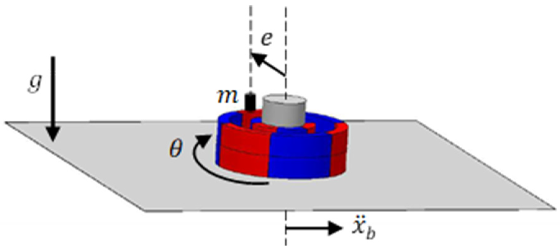
2.2. The Proposed Concept

In this paper, a magnetic pendulum is proposed with the scope to address the limitations described in Section 2.1, focusing on overcoming the issues of weak amplitude for low-frequency vibrations. A schematic representation of the concept is shown in Figure 1a. The stator (s) is placed around a static mounting rod, whereas the rotor (r) is free to rotate with respect to the common center point (denoted with a black dot). The airgap (a) of thickness a g is interposed to separate the rotor and the stator, being a rather critical design parameter, and it will be discussed later. An even number of 2 n p p magnets is arranged in circular arrays with alternating polarity in n p p pole pairs at both the rotor and the stator. The magnets are constrained to an even number to result in an integer number of equidistant equilibria. Note that the proposed oscillator exhibits an equal number of stable and unstable equilibria, for example, a realization with six magnets in the rotor and six corresponding magnets in the stator (i.e., n p p = 3 pole pairs) would have three stable and three unstable equilibria. Throughout this work, we focus on the mechanical aspect of the magnetic pendulum, and thus, the harvesting circuitry is taken at its simplest form for electromagnetic VEHs. The electrical subsystem of the harvester is considered to be 2 n p p multilayer coils mounted on the stator and arranged radially to face the rotor magnets, with each coil connected to an identical load with resistance R l . Neglecting the generally small inductance of the coils, the circuits amount to an additional electrical parasitic damping where the dynamic response of the harvester is concerned. Neglecting the inductance is not expected to induce severe errors, given the ultra-low vibration frequencies and the generally small size of the coils. Of course, advanced power management and voltage rectification would be required in a practical application of the VEH. However, the current paper is focused on investigating the benefits of the nonlinear mechanical response of magnetic pendula, and therefore, secondary energy losses at the power management circuitry are neglected.
For simplicity, all magnets are considered to have equal width w perpendicularly to the plane of rotation and equal radial thickness t , resulting in larger arc lengths for each magnet on the rotor. The pairs are adjusted such that opposite magnets in the rotor and the stator have the same polarity for zero angular displacement θ of the rotor, leading to a system with multiple equilibria, equal to the number of pole pairs. For example, the particular case shown in Figure 1a with four pole pairs exhibits four stable equilibrium positions as denoted in the illustration.
Pendulum dynamics are introduced in the proposed concept via the magnetic interactions developed between the permanent magnets of the rotor and the stator. When the rotor is displaced to an arbitrary displacement θ, the stator magnets apply a restoring torque that tends to counteract this displacement, similarly to a nonlinear torsional spring. In fact, the symmetric pattern of the proposed design is shown to produce an almost sinusoidal restoring torque (Section 2.3.1) that closely emulates the gravitational restoring torque of classical gravitational pendula, alas, without any dependence on the gravitational accelerations, such that the proposed VEH could be realized even with a purely balanced pendulum system. Furthermore, the analysis in the following section shows that the magnitude of the restoring torque (Figure 1b) is decoupled from the mass distribution of the rotor and the gravitational potential well, which is a critical limitation in traditional gravitational pendulum VEHs, and it is largely flexible against its size, since it is directly determined by the intensity of the interacting magnetic fields. The latter depend on a multitude of design control parameters: namely, magnet grade, rotor and stator geometry and size and airgap properties. This allows for manipulating the oscillator’s potential well according to the tuning requirements, irrespectively of gravity and the balance or imbalance of the rotor.

2.3. Mathematical Model

In this section, a mathematical model is developed to study the dynamics inherent to the proposed concept. First, a model of the magnetic restoring torque is developed using the so-called charge model [40], and then, a reduced SDOF model of the mPVEH is used to analyze the system response. The magnetic oscillator is also coupled with an electric harvesting circuit to calculate the expected power output.

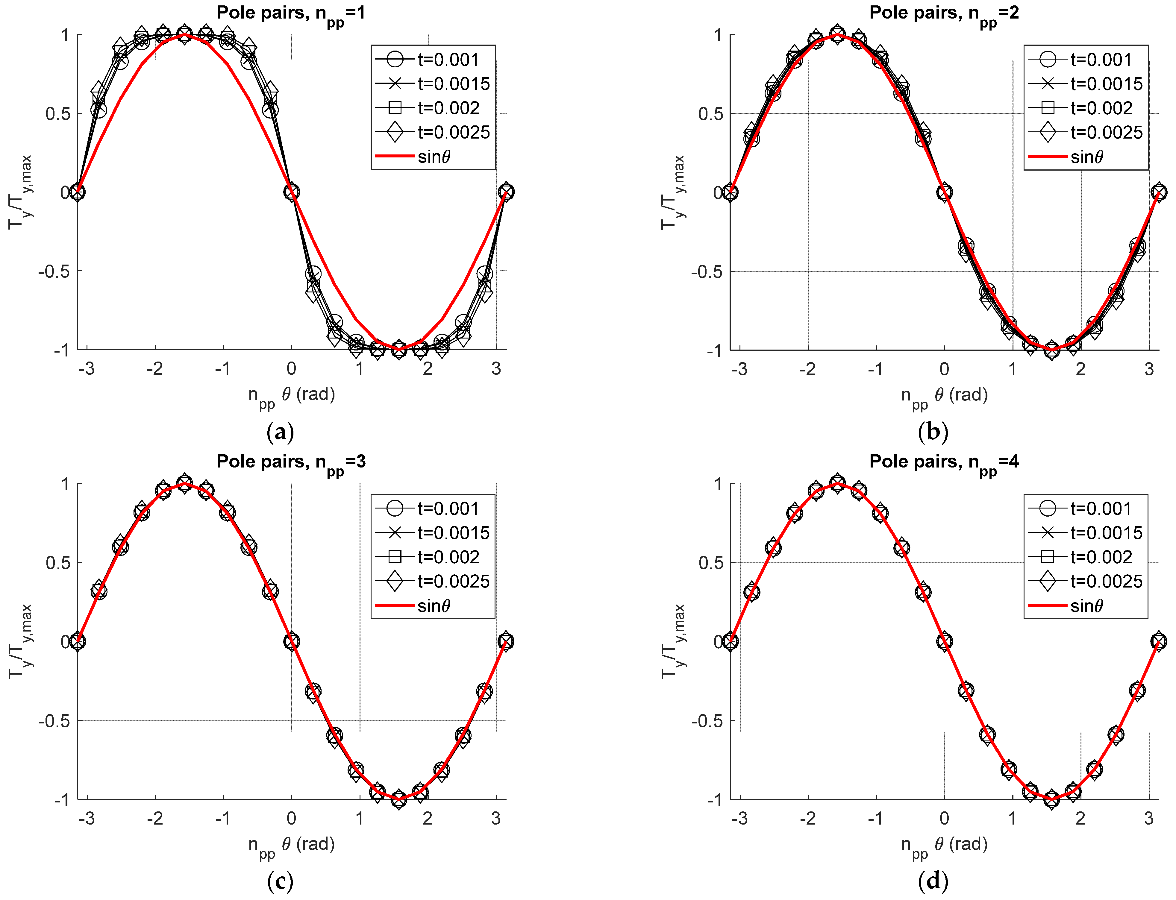
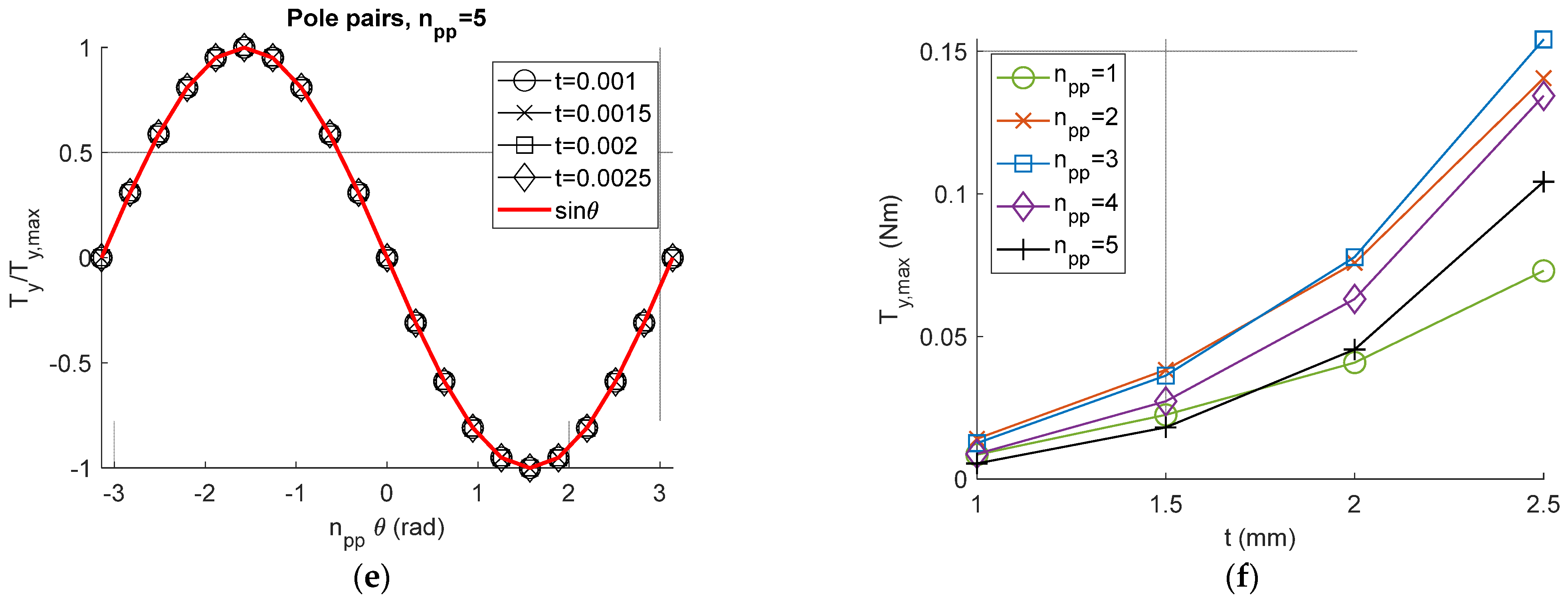
2.3.1. Restoring Magnetic Torque

A model of the restoring torque acting on the rotor–stator system is necessary to understand the design principles underlying the proposed concept and to highlight possible limitations. Several authors concerned with VEH have considered the relatively simple dipole model to account for magnetic forces. However, this approach requires large separation distances which cannot hold for the magnetic arrays considered herein. Furthermore, the magnetic fields of permanent magnets are prone to weakening effects from their own intensity fields captured by the related permeance coefficient that leads to weaker operating points, whereas avoiding demagnetization from interacting magnets delimits the breadth of the foregoing analysis to large airgaps. As a result, the so-called charge model is used for calculating the restoring torque at the concept’s design space, validated with pertinent FEA results. This approach discretizes the magnetic body to a finite number of magnetic dipoles, thus involving the impact of the magnet’s geometry. The results are also validated with FEA analysis to exclude the possibility of demagnetization.
Referring to Figure 1a and the associated parameters, the restoring torque on the rotor is calculated numerically using the following formula [40], p. 142:
T = V ρ m r × B e x t d v + S σ m r × B e x t d s
where the mentioned notation is used and bold indicates a vector. Effectively, the volume V of the magnets and the surface areas S to which the magnetization is normal, i.e., the inner and outer arc surfaces of the magnets, are discretized with a spatial grid on a cylindrical coordinate system ( r i , ϕ i   , z i ) for the rotor and ( r j   , ϕ j , z j ) for the stator, with the origins at their common center. Note that the 3D grid indices are omitted for ease of presentation. Then, the total torque is calculated with a numerical iterative procedure as follows:
T y = μ 0 4 π i , j = 1 2 n p p ( T V i V j + T S i V j + T V i S j + T S i S j )
where summation arguments refer to the torques induced by volume-to-volume, surface-to-volume, volume-to-surface, and surface-to-surface magnetic interactions between the i-th rotor magnet volume and the j-th stator magnet. Subscripts V i , V j denote all the nodes belonging to the i-th rotor magnet volume and the j-th stator magnet, respectively, and S i k , k = 1, 2 denotes the node sets on the two polarized face surfaces of the i-th outer magnet and S j l , l = 1, 2 the corresponding ones relating to the j-th inner magnet. The torque arguments in Equation (4) are given by the following [40]:
T V i V j = V i V j ρ i ρ j r i r j sin ( ϕ i ϕ j ) D i j 3 T S i V j = S i k , k = 1,2 V j σ i ρ j r i r j sin ( ϕ i ϕ j ) D i j 3 T V i S j = V i S j k , k = 1,2 ρ i σ j r i r j sin ( ϕ i ϕ j ) D i j 3 T S i S j = S i k k = 1,2 S j l , l = 1,2 σ i σ j r i r j sin ( ϕ i ϕ j ) D i j 3
with
D i j = r i 2 + r j 2 2 r i r j cos ϕ i ϕ j + z i z j 2
where ρ i , j = M ^ s i , j = M s i , j d r d ϕ d z is the volume charge, σ i , j = M ^ S i , j n ^ = M s i , j r i , j d ϕ d z is the surface charge, and M s i , j = B r i , j / μ 0 is the magnetization of the i-th rotor and j-th stator magnets across the radial coordinate with alternating direction. B r i , j is the remnant magnetic flux density of the material, and n ^ is the normal vector to each magnet’s faces. The reader is referred to [40] for a detailed discussion of the use of the charge model for calculating force and torque between permanent magnets.
Figure 2 shows the restoring torque of the rotor for various pole pairs. The computed torque is normalized to unity, and it is shown against a scaled angle n p p θ in order to facilitate comparison of the torque profiles. The numerical results were produced for a theoretical case study whereby the stator’s inner diameter was kept constant at 10 mm and the rotor’s outer diameter at 30 mm. The spatial grid used a constant size of d r = 0.2 mm, d ϕ = π / 60 and d z = 1.7 mm. This approach was preferred in order to highlight the concept’s flexibility within a given space constraint, which is typically an issue that has to be satisfied in VEH applications and, in fact, a rather pressing one when low-frequency concepts are concerned due to typically larger displacement amplitudes. Different thickness values t were considered starting from 1 mm up to 2.5 mm, which were applied to both the rotor and the stator magnets. Hence, the airgap was kept at a g = 10 2 t mm, varying from 8 mm down to 5 mm correspondingly. Moreover, each graph contains a pure sine wave that effectively describes the normalized potential well of a gravitational pendulum. The purpose of this exercise is to elucidate the mathematical pattern of the torque produced across the angular displacement range of the proposed concept and to compare it with the one expected in a typical pendulum VEH. Figure 2a–e reveal that the restoring torque closely follows a sinusoidal function of the displacement. In particular, for two pole pairs and above, the deviation of the restoring torque from a pure sine wave is clearly negligible. For a single pole pair, the departure is more substantial with R 2 = 0.9633; however, a single pole pair would not be a preferential option anyway since it can be reasonably expected that more pole pairs would lead to higher rates of harvesting coil flux density variations. Consequently, the proposed magnetic concept can be confidently expected to emulate the dynamics of traditional gravitational pendula for a broad range of design space parameters.
Additionally, Figure 2f shows the computed maximum torque for each case. It is noteworthy that the cases with n p p = 2, 3 are shown to produce a maximum torque magnitude with respect to the other options, almost regardless of the magnets’ thickness. Moreover, it is quite sensible that thicker magnets are shown to lead to harder magnetic torsional springs. Based on these, the pole pairs and the magnets’ size can be used to scale the resulting restoring torque to the levels required for frequency and amplitude tuning. However, an important observation from this graph is the vast design space that the features of the proposed concept create with respect to the restoring potential well. The torque magnitude attains values from about 0.005 Nm up to around 0.155 Nm, utilizing a confined available space and without necessarily having to resort to any eccentricity or a precise total inertia. The variation in the magnets’ thickness can be easily compensated by non-magnetic material, showing that a constant rotor inertia—even balanced in principle—offers a design space that covers an almost 30-fold increase in the restoring torque, without any influence from possible variations in the plane of rotation. Note that this is achieved without considering the readily available option to use less and/or smaller magnets in the stator. In other words, the proposed magnetic pendulum concept offers a design space that can fulfill the pendulum-based VEH tuning requirements in a correspondingly broad frequency range. On the other hand and under the same constraints of fixed space and inertia, the gravitational counterpart could only be tuned to a specific frequency that would come with detrimental sensitivity to the system’s orientation in space.
The ensuing analysis has not hitherto considered the effects of permeance and possible external H-field demagnetization. Although permeance is expected to cause minor weakening of the magnetic fields, external demagnetization is quite unlikely to do so due to the relatively large radial distance between the magnets. Nevertheless, an FEA model was developed in Simcenter Magnet 2022.1® to verify these reasonable predictions. The case with n p p = 3 and t = 2.5 mm was selected since it is expected to demonstrate the higher risk of demagnetization. Indeed, the model using 3,330,000 tetrahedra of 0.5 mm maximum size for the magnets and an airbox verified that the above analysis is not susceptible to demagnetization issues. Figure 3a shows the field plot for the Demagnetization Proximity, a Magnet® metric that quantifies the risk of demagnetization, effectively subtracting the computed H-field value in the mesh from the knee point and expressing it in normalized form. Positive proximity values signal a demagnetization issue, whereas negative values indicate a safe magnetic circuit. It is noticed that the maximum computed value is −0.1347, which builds confidence on the aforementioned analysis. Furthermore, as Figure 3b depicts, the FEA model produced a result extremely close to the torque calculated with the charge model with a magnitude of 0.153 Nm for the former and 0.1534 Nm for the latter.

2.3.2. Equation of Motion

After obtaining validated data for the restoring torque developed in the magnetic pendulum system, the equation of motion of the VEH can be developed. For simplicity, we assume that the VEH’s pivot vibrations x ¨ b lies within a horizontal plane perpendicular to gravity and that the parametric excitation term is produced by an eccentricity of the rotor, m e (Figure 4) which, nevertheless, does not affect the VEH’s conservative dynamics due to the horizontal constraint of the plane of rotation. These assumptions are only used herein to reduce the system complexity for the ensuing analysis. Nonetheless, one could readily conceive of an arrangement without the horizontal constraint leading to a combination of magnetic and gravitational torques. However, we hold these assumptions in order to simplify the foregoing analysis that aims to elucidate the potential of magnetic pendula for VEH. Then, the equation of motion of the mPVEH is written as follows:
I r θ ¨ + c m + c e θ ˙ + T 0 sin n p p θ m e x ¨ b sin θ = 0
where I r denotes the rotor moment of inertia. T 0 is the magnitude of the restoring torque at the angular position where each rotor magnet faces a stator pole pair. The analysis in Section 2.3.1 justifies the assumption used in Equation (1) that the torque has a purely sinusoidal profile, whereas the mentioned computational procedure can be used to determine T 0 for a given design. It can be readily observed from linearizing Equation (1) that the magnetic pendulum has a natural frequency for which Ω m 2 = n p T 0 / I r , i.e., completely independent from gravity and any possible eccentricity. In principle, the VEH’s conservative dynamics are also independent from the orientation of the rotor’s plane of rotation, given that the eccentricity is not essential to realize the conservative dynamics. Therefore, tuning the system to a desired frequency can be accomplished with the magnetic torque, apart from the traditional influence of the moment of inertia, allowing the possibility to use versatile lightweight concepts. Furthermore, normalizing time using τ = Ω m t and the angle using ϕ = n p θ , and again assuming harmonic base displacement leads to the following:
ϕ + ( γ m + γ e ) ϕ + sin ϕ + λ m cos ν m τ sin ϕ n p = 0
where γ m = c m / Ω m I r , γ e = c e / Ω m I r , ν m = ω / Ω m and λ m = m e A ω 2 / T 0 . From a design perspective, it is noticed that this equation describes the dynamics of a parametrically excited pendulum for which frequency and amplitude tuning are controlled with increased flexibility from each other, despite the parallel dependence on the eccentricity m e and the magnetic torque T 0 . Note also that they are both completely independent from gravity and the VEH’s orientation. The design problem is then converted to an exercise of finding the desired parameter set for given excitation frequencies and amplitudes. This is a promising feature that allows adjusting the VEH to the expected vibration magnitude at the design stage, an option that is not available with existing pendulum VEHs. This is readily deduced by comparing the expressions of the nondimensional amplitudes λ and λ m with each other. Effectively, the former is the given host vibrations in g units over which there are no design degrees-of-freedom, whereas the latter can be adjusted by properly scaling the ratio of the eccentricity to the magnetic torque. Recall that maintaining a desired frequency tuning can additionally be achieved by adjusting the balanced inertia term. Consequently, the magnetic pendulum system represents a linear-to-rotary VEH whereby the nondimensional parameters ν m and λ m controlling the parametric response type can be designed-for with substantial flexibility. This is a considerable step forward for nonlinear VEH since existing pendulum concepts were hitherto confined to frequency tuning only.
In order to demonstrate this, an exploration of the parameter space is conducted for fixed vibration input of 0.2 g magnitude at 2 Hz considering a maximum possible balanced inertia of 20 kgmm2 fitting a 30 × 10 mm3 space. Figure 5a shows colormaps of the resultant λ m over the eccentricity and the magnetic torque. The contours demonstrate the potential to adjust the system parameters such that a desired amplitude tuning can be achieved, whereas the rotational response needs finer amplitude tuning depending on the frequency ratio. Furthermore, Figure 5b,c show shaded areas enclosing values of ν m [ 1.5,3.5 ] for various values of the balanced inertia I 0 , suggesting that a broad range of tuning parameters may result in the preferred frequency ratio. It is therefore observed that the proposed pendulum VEH nondimensional frequency and amplitude specifications can be tuned to the parameter space regions expected to lead to the rotational response regime ( λ > 1 ), despite the assumed weak 0.2 g vibration magnitude. The following section aims to demonstrate the impact of these advantageous design features on the establishment of rotational vibration harvesting with numerical calculations of frequency and amplitude response curves and a representative design case study.

3. Numerical Results

In this section, Equations (6) and (7) are numerically integrated to assess the potential response regimes of the proposed magnetic pendulum. Firstly, the normalized equation of motion shown in Equation (7) is used to produce parameter space plots of the pendulum response for various pole pairs, highlighting the parameter space regions leading to unidirectional rotary response. Then, frequency and amplitude response curves are plotted to better understand the response regime structure, along with selected time histories and phase portraits. Finally, informed by the ensuing analysis, the response and power output of a design case study is numerically evaluated via integration of Equation (6). In all succeeding results, the integration is conducted using a MATLAB R2024a® built-in solver with a maximum time step of d τ = 2 π / ν / 100 and d t = 2 π / ω / 100 correspondingly, and for 1000 excitation periods.

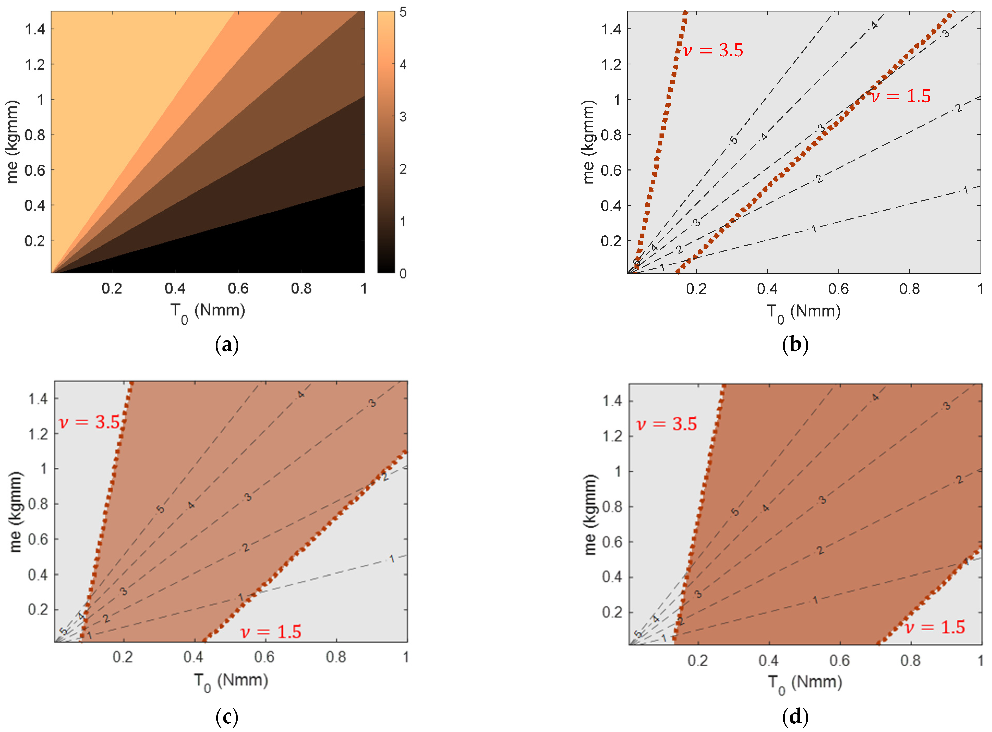
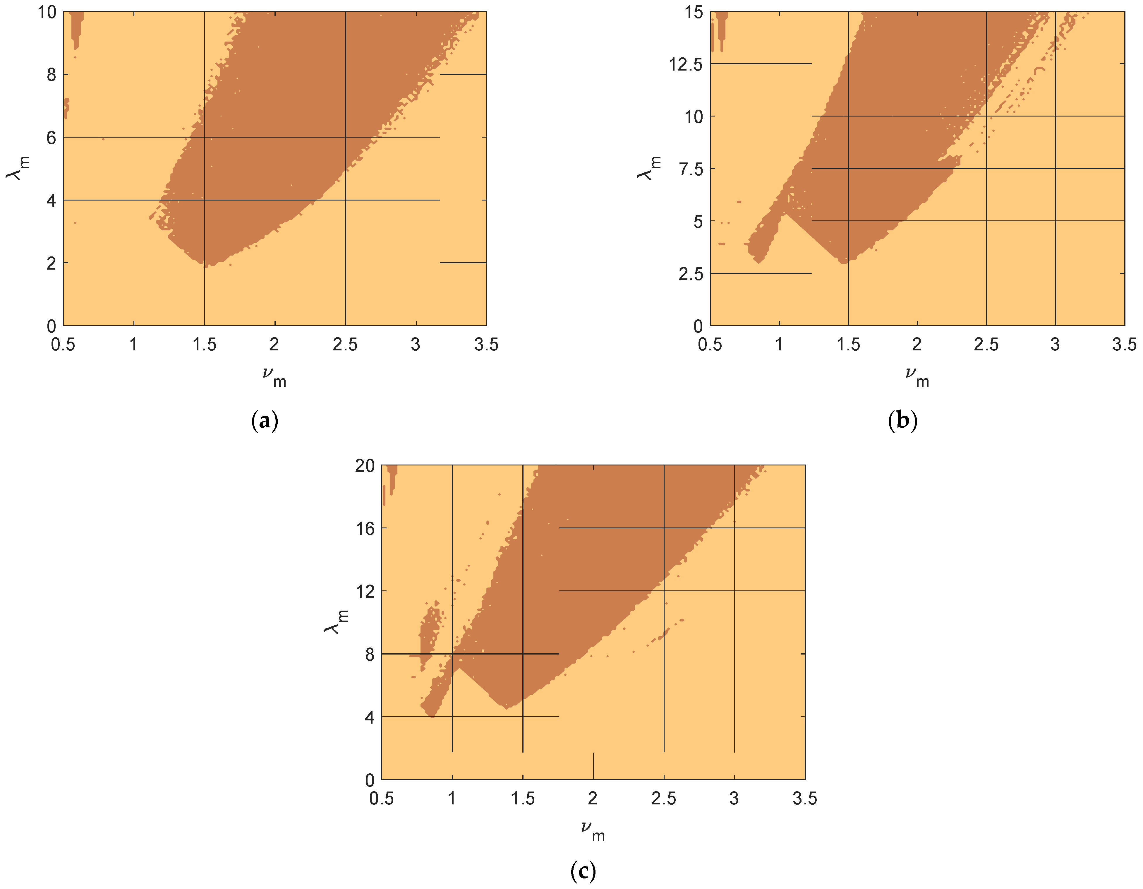
3.1. Parameter Space Plots

The first step in the analysis is to produce parameter space plots distinguishing the regions where the magnetic pendulum performs a stable unidirectional response. This is accomplished by numerical integration of the governing equation of motion for various frequency and amplitude ratios in the range ν = [ 0.5,3.5 ] and λ = [ 0,5 n p p ] , considering three arrangements of the pole pairs, n p p = 2, 3 and 4. The case of one pole pair is left out since the resulting normalized equation of motion is identical to that of a parametric gravitational pendulum. Each point in the space plot is examined for rotational steady-state response. This is accomplished by tracking the average value of the pendulum angular velocity, < ϕ > , for the last 500 periods. This metric is suitable to identify the establishment of unidirectional steady-state rotations, since in such a case it is expected to be ~ 2 ν . Stable fixed point and oscillatory response are expected to have a mean velocity of about 0, while mixed oscillatory rotary, bidirectional rotary, and chaotic are expected to have a mean angular velocity that is considerably lower than 2 ν . Furthermore, we do not distinguish clockwise from anticlockwise rotational response by taking the absolute value of the mean velocity. Therefore, parameter space regions of unidirectional steady-state rotations are tracked with reasonable accuracy of the boundaries.
Figure 6 shows the distinction of parameter space regions tuning the magnetic pendulum to rotary steady response for n p p = 2,3 , 4 correspondingly. Dark shaded areas correspond to regions of unidirectional rotations, whereas light shaded areas correspond to any other response regime. The integration of each ( ν , λ ) point starts from the same initial conditions of (0.1 π , 0), i.e., we are not performing a continuation analysis since this would introduce a bias in the evaluation of the response. Note that we extend the plots up to a λ m value that depends on the number of pole pairs. This is carried out based on the linearized version of the equation of motion where the parametric driving term is normalized by n p p . It is therefore surmised that increasing pole pairs would require higher input energy. Indeed, the depicted rotational regions show a consistent pattern for the minimum required amplitude, which is nearly proportional to the number of pole pairs. This is against the initial effort of providing easier access to the rotational space; however, one should note that the plotted λ m can be manipulated at the design stage via the ratio of the eccentricity over the magnetic torque, an option that has not been available for alternative pendulum-based VEHs. In fact, weak pivot vibrations (<<1 g) would trap a gravitational pendulum well below the rotational region, within a broad frequency range of stable fixed points and a limited band of oscillatory motion. On the contrary, as will be demonstrated later, weak vibrations can be properly scaled in the proposed concept such that the resulting λ m falls within the rotational parameter space region.

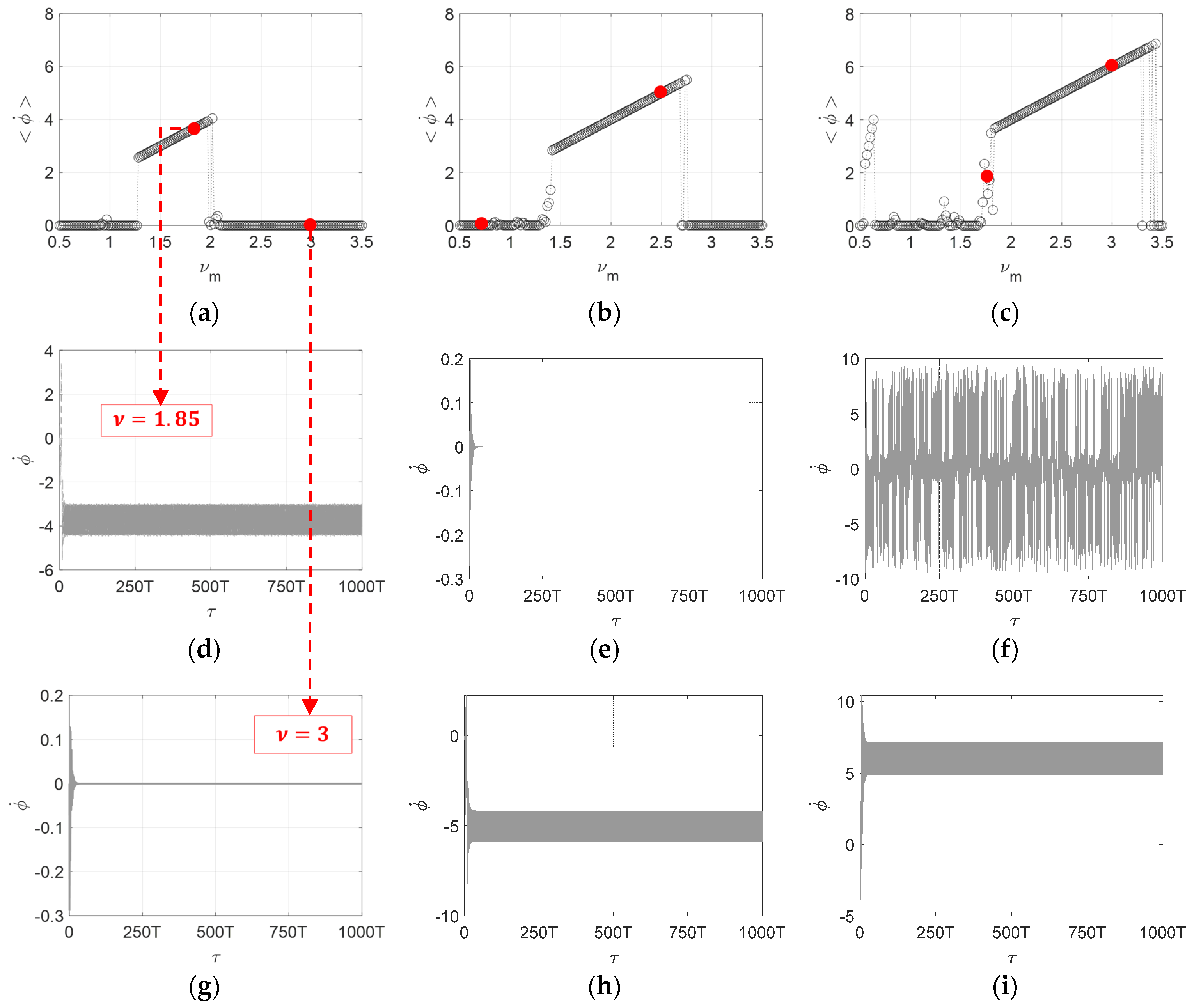
3.2. Frequency and Amplitude Response Curves
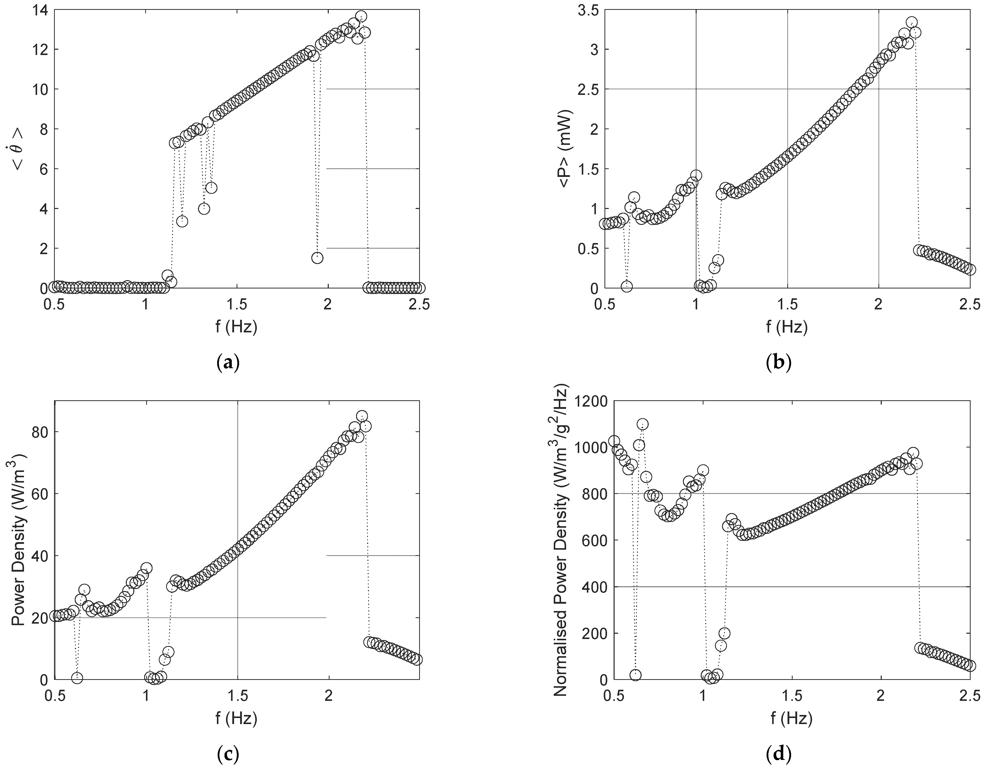
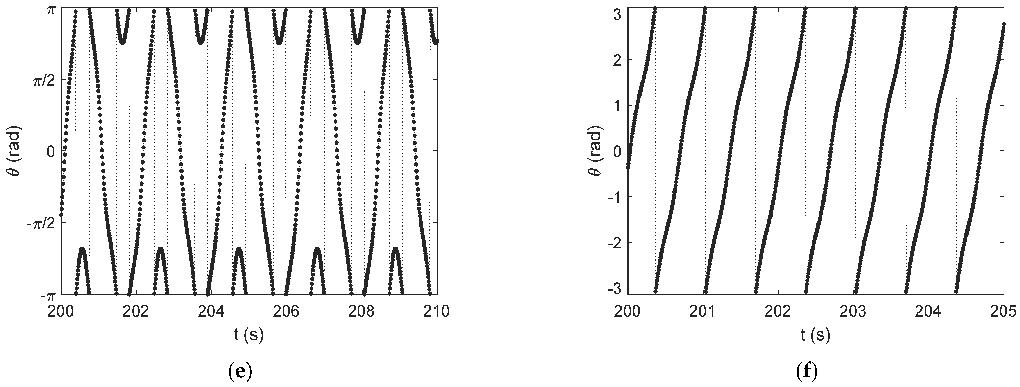
Another interesting observation is the rather broad frequency range of the regions corresponding to rotational response. This is better illustrated in the frequency response curves (FRCs) shown in Figure 7a–c for three λ m values. Selected time histories are shown in Figure 7d–i to verify the identified response, denoted on the FRCs with red circles. Note the response recorded for ν = 1.75 shown in Figure 7f that depicts an irregular response pattern of oscillations and rotations of mixed direction, where the mean velocity was computed below the expected value for rotations. This verifies that the mean angular velocity adequately identifies unidirectional rotations, such as the ones shown in Figure 7d,h,i for which the mean velocity was computed at 2 ν . As the amplitude increases from Figure 7a–c, the frequency band leading to rotary response increases as well, providing a promising measure to exploit the system nonlinearities. Note also that, despite the variation in the amplitude, the mean velocity for all unidirectional rotations is equal to 2 ν , which implies that for a given frequency, the rotary response of the pendulum remains fairly consistent under amplitude variations.
Motivated by the previous remark, amplitude response curves are shown to graphically illustrate the effect of increasing amplitude. Given that the rotary response regions have already been identified for the considered cases, the mean-squared velocity is now plotted in Figure 8a against the amplitude λ m for ν = 2 and n p p = 2. Considering that damping is taken constant at γ m = γ e = 0.1, this is selected as a measure that closely tracks the power output capacity of the harvester, although in nondimensional form. Observing the plotted graph, the response expectedly starts from a stable fixed point response, followed by the onset of oscillations between approximately λ m = (1, 3). As the amplitude increases, the pendulum swing angles increase as well, leading to mild increase in the mean-square velocity. However, once the global bifurcation boundary is crossed at about λ m = 3, an upwards step change is recorded of over x8 increase in the mean-squared velocity, attributed to the onset of rotations. These response types are also verified with phase portraits in Figure 8b,c.
As a result, the presented amplitude response curve reveals that the rotational response regime has multiple times higher power generation capacity than the oscillatory counterpart. In that sense, the proposed concept aims at overcoming the amplitude limitations for pendulum-based VEHs in order to facilitate rotary harvesting and the consequent expected improvements in the power output, showcased by the response curve in Figure 8a. However, the onset of rotations is largely inhibited by the damping present in the VEH, that is, by the power-extracting circuitry among others. It is therefore necessary to document the impact of damping on the mean-square velocity. Figure 8d shows < ϕ 2 > against the inverse of the electrical damping ratio, γ e , for a moderate value of λ m = 3. Interestingly, once the damping falls below the threshold corresponding to the selected amplitude for the rotational response to emerge, the mean-squared velocity attains an almost constant value. This suggests that the proposed pendulum VEH may operate over a broad frequency range (see Figure 7a–c) and, at the same time, maintain relatively consistent power output as long as it is attracted to the rotational response.

3.3. Case Study

The nondimensional analyses in the previous sections highlighted the features of utilizing magnetic interactions as the basis for the potential energy of a pendulum VEH. Moving on, a case study is studied numerically in order to show the potential of the proposed concept with dimensional quantities. Specifically, a low-frequency band is targeted between 0.5 and 2.5 Hz, assuming weak vibration amplitudes of 0.2 g. Table 1 enlists the parameters used in this preliminary analysis. The rotor and stator magnets are placed at a radial distance from the center of rotation such that they coincide with the corresponding listed diameters. Hard N42 magnets are used in the rotor, and soft ferrite magnets are used for the stator, leading to a weak restoring torque of 0.5 Nmm magnitude. All permanents magnets are assumed to be 5 mm thick. Noteworthy, the space utilized is confined at less than 20 cm3, which is considerably lower than the ones reported for other low-frequency VEHs (see Wang [19]).
The parameters used for this demonstration lead to a frequency band corresponding to circa ν   ( 0.55,2.77 ) for a nondimensional amplitude of λ = 4.71 . Consequently, Figure 6a is anticipated to describe the VEH response, revealing that a large band of rotary response is expected. Indeed, Figure 9a verifies the utilization of the nondimensional analysis. Computing the magnetic pendulum response using the dimensional equation of motion shown in Equation (6) and the analytical-FEA workflow described in Section 2.3.1 to compute T 0 shows the predicted broad band of rotary response to weak low-frequency vibrations. Notably, the load power is shown to follow a steady pattern of nearly proportional increase with respect to the base frequency within the rotary response boundaries from ca. 1.15 Hz up to 2.2 Hz. The delivered power is much greater than the power generated by bounded oscillations of the rotor within the [ π , π ] , observed in the region at a higher end of the considered band, above ca. 2.2 Hz. This is also reported in Figure 10 where a parametric analysis with respect to the load resistance R l is conducted, effectively reducing the damping ratio by increasing the resistance. A steep step increase in power output is recorded when the damping becomes low enough such that the rotor enters the rotational response region, despite the weak 0.2 g vibrations. Note that when rotary motion is established, the average speed is nearly independent from the damping ratio, leading to relatively consistent power output. The observed variation in the power output is attributed to deviation from impedance matching (at ca. 3 Ohms), which nonetheless exhibits a relatively low sensitivity to fine tuning.
Moreover, Figure 9c,d reveal a substantial power density of up to ca 80 W/m3 (or μW/cm3). When the normalized power density is considered, triggering the rotary motion via the primary parametric response exhibits a maximum value of ca. 1000 W/m3/g2/Hz which is orders of magnitude bigger than typical low-frequency VEHs reported in the literature (see, for example, corresponding tables in [19,41]). The increased power density is a result of the adjustable potential well that can trigger the onset of rotary motion for low-frequency weak-amplitude vibrations. Interestingly, the multiple pole pairs and the associated equilibria give rise to another distinct region of similarly efficient power densities at ultra-low frequencies (<1 Hz). In fact, the mean angular velocity is capable of capturing unidirectional rotations only. The frequency response curves in Figure 9a–d demonstrate that before the primary resonance where unidirectional rotations are recorded (Figure 9f), significant power can be harvested via inter-well oscillations observed as jumps between the two stable equilibria at as low as 0.5 Hz, converted to even bidirectional rotations that overcome the ± π barrier, such as the time history shown in Figure 9e. This reveals the potential of the proposed concept for harvesting vibration energy from a large band of ultra-low- and low-frequency vibrations with a mild acceleration magnitude of 0.2 g.
Furthermore, an additional frequency response is presented in Figure 11 for a constant displacement amplitude of the base of 12 mm, i.e., with an input acceleration varying from 0.01 g for 0.5 Hz up to 0.3 g at 2.5 Hz. This is motivated by the fact that mechanical vibrations at this low end of the frequency spectrum are typically controlled by kinematic rather than forcing inputs (e.g., wearables). Figure 11 shows the average power harvested by the electrical load and the corresponding normalized power density. The magnetic pendulum VEH enters the rotational response just below 1.2 Hz corresponding to a base acceleration of less than 0.07 g. A remarkable consistency of the harvested power density is observed in Figure 11b for higher frequencies. Note that a purely inertial VEH with the static magnets removed (i.e., with T 0 = 0) is bounded to low amplitude oscillations about a stable equilibrium under the same driving conditions. The introduction of the more flexibly adjusted restoring torque employs the primary parametric resonance leading to stable unidirectional rotations. Effectively, as long as the VEH responds with stable rotations, the harvested power becomes proportional to the base acceleration and nearly independent of the driving frequency. Although further investigations are required in various aspects of the proposed concept, the purely magnetically induced pendulum dynamics offers a potential solution to the persisting bandwidth problem for ultra-low-frequency vibration energy harvesting.

4. Conclusions

In this paper, a novel magnetic pendulum was proposed for harvesting vibration energy from low-frequency weak vibrations. The conservative dynamics of the proposed device are due to the magnetic interactions developed between a purely balanced rotor and a stator, both carrying permanent magnets. The key feature of this concept is the adjustability of the restoring torque via the employment of properly sized and placed permanent magnets, which leads to a far more flexible design with respect to tuning the device to the primary parametric resonance, especially when low-frequency weak vibrations are concerned. The conducted analyses showed that the strength of the magnetic fields offers an additional design degree-of-freedom, on top of the traditional adjustment of the rotor’s inertia. Utilizing this, the pendulum VEH can be tuned to a targeted low frequency, whilst allowing for adjusting the nondimensional excitation amplitude such that the pendulum enters the rotational response regime. Numerical investigations of the concept’s VEH performance have revealed that a substantial power density of over 600 W/m3/g2/Hz can be expected within a low-frequency range of 0.5–2.5 Hz under weak inputs of 0.2 g. Although the proposed system was studied under strict constraints, such as the vertical orientation of the pendulum’s axis of rotation, the concept can be readily extended to an arbitrary orientation considering the combined effect of gravity and appropriately scaled magnetic fields. The presented results form a promising basis for future development of the concept towards establishing the relevant technical know-how for linear-to-rotary energy harvesting from weak low-frequency vibrations in versatile applications.

Author Contributions

Conceptualization, P.A.; Software, M.I.T.; Validation, M.I.T. and P.A.; Formal analysis, P.A.; Investigation, P.A.; Writing—original draft, M.I.T.; Writing—review & editing, P.A.; Visualization, M.I.T.; Supervision, P.A.; Project administration, P.A. All authors have read and agreed to the published version of the manuscript.

Funding

This research received no external funding.

Data Availability Statement

The original contributions presented in the study are included in the article, further inquiries can be directed to the corresponding author.

Conflicts of Interest

The authors declare no conflict of interest.

References

  1. Ells, D.A.; Mechefske, C.; Lai, Y. Innovative electromagnetic vibration energy harvester with free-rotating mass for passive resonant frequency tuning. Appl. Energy 2025, 377, 124622. [Google Scholar] [CrossRef]
  2. Muscat, A.; Bhattacharya, S.; Zhu, Y. Electromagnetic Vibrational Energy Harvesters: A Review. Sensors 2022, 22, 5555. [Google Scholar] [CrossRef] [PubMed]
  3. Sezer, N.; Koç, M. A comprehensive review on the state-of-the-art of piezoelectric energy harvesting. Nano Energy 2021, 80, 105567. [Google Scholar] [CrossRef]
  4. Wei, C.; Jing, X. A comprehensive review on vibration energy harvesting: Modelling and realization. Renew. Sustain. Energy Rev. 2017, 74, 1–18. [Google Scholar] [CrossRef]
  5. Priya, S.; Inman, D.J. (Eds.) Energy Harvesting Technologies; Springer: Boston, MA, USA, 2009. [Google Scholar] [CrossRef]
  6. Ylli, K.; Hoffmann, D.; Willmann, A.; Folkmer, B.; Manoli, Y. Human motion energy harvesting: Numerical analysis of electromagnetic swing-excited structures. Smart Mater. Struct. 2016, 25, 095014. [Google Scholar] [CrossRef]
  7. Iqbal, M.; Nauman, M.M.; Khan, F.U.; Abas, P.E.; Cheok, Q.; Iqbal, A.; Aissa, B. Vibration-based piezoelectric, electromagnetic, and hybrid energy harvesters for microsystems applications: A contributed review. Int. J. Energy Res. 2020, 45, 65–102. [Google Scholar] [CrossRef]
  8. Li, Y.; Sun, Z.; Huang, M.; Sun, L.; Liu, H.; Lee, C. Self-Sustained Artificial Internet of Things Based on Vibration Energy Harvesting Technology: Toward the Future Eco-Society. Adv. Energy Sustain. Res. 2024, 5, 2400116. [Google Scholar] [CrossRef]
  9. Barton, D.A.W.; Burrow, S.G.; Clare, L.R. Energy Harvesting from Vibrations with a Nonlinear Oscillator. J. Vib. Acoust. 2010, 132, 021009. [Google Scholar] [CrossRef]
  10. Boisseau, S.; Despesse, G.; Seddik, B.A. Nonlinear H-Shaped Springs to Improve Efficiency of Vibration Energy Harvesters. J. Appl. Mech. 2013, 80, 061013. [Google Scholar] [CrossRef]
  11. Mann, B.; Sims, N. Energy harvesting from the nonlinear oscillations of magnetic levitation. J. Sound Vib. 2009, 319, 515–530. [Google Scholar] [CrossRef]
  12. Cottone, F.; Vocca, H.; Gammaitoni, L. Nonlinear Energy Harvesting. Phys. Rev. Lett. 2009, 102, 080601. [Google Scholar] [CrossRef] [PubMed]
  13. Alevras, P.; Theodossiades, S.; Rahnejat, H. On the dynamics of a nonlinear energy harvester with multiple resonant zones. Nonlinear Dyn. 2018, 92, 1271–1286. [Google Scholar] [CrossRef]
  14. Sommermann, P.; Cartmell, M.P. The dynamics of an omnidirectional pendulum harvester. Nonlinear Dyn. 2021, 104, 1889–1900. [Google Scholar] [CrossRef]
  15. Daqaq, M.F.; Masana, R.; Erturk, A.; Quinn, D.D. On the Role of Nonlinearities in Vibratory Energy Harvesting: A Critical Review and Discussion. Appl. Mech. Rev. 2014, 66, 040801. [Google Scholar] [CrossRef]
  16. Morel, A.; Badel, A.; Gasnier, P.; Gibus, D.; Pillonnet, G. Short Circuit Synchronized Electric Charge Extraction (SC-SECE): A tunable interface for wideband vibration energy harvesting. arXiv 2018, arXiv:1808.04461. [Google Scholar] [CrossRef]
  17. Sun, R.; Zhou, S.; Cheng, L. Ultra-low frequency vibration energy harvesting: Mechanisms, enhancement techniques, and scaling laws. Energy Convers. Manag. 2023, 276, 116585. [Google Scholar] [CrossRef]
  18. Castagnetti, D. A simply tunable electromagnetic pendulum energy harvester. Meccanica 2019, 54, 749–760. [Google Scholar] [CrossRef]
  19. Wang, T. Pendulum-based vibration energy harvesting: Mechanisms, transducer integration, and applications. Energy Convers. Manag. 2023, 276, 116469. [Google Scholar] [CrossRef]
  20. Ma, T.-W.; Zhang, H.; Xu, N.-S. A novel parametrically excited non-linear energy harvester. Mech. Syst. Signal Process. 2012, 28, 323–332. [Google Scholar] [CrossRef]
  21. Alevras, P.; Theodossiades, S.; Rahnejat, H. Broadband energy harvesting from parametric vibrations of a class of nonlinear Mathieu systems. Appl. Phys. Lett. 2017, 110, 233901. [Google Scholar] [CrossRef]
  22. Lee, B.; Chung, G. Design and analysis of a pendulum-based electromagnetic energy harvester using anti-phase motion. IET Renew. Power Gener. 2016, 10, 1625–1630. [Google Scholar] [CrossRef]
  23. Yakubu, G.; Olejnik, P.; Adisa, A.B. Variable-Length Pendulum-Based Mechatronic Systems for Energy Harvesting: A Review of Dynamic Models. Energies 2024, 17, 3469. [Google Scholar] [CrossRef]
  24. Zhang, C.; Xu, J.; Fang, S.; Qiao, Z.; Yurchenko, D.; Lai, Z. A pendulum-based absorber-harvester with an embedded hybrid vibro-impact electromagnetic-dielectric generator. Nano Energy 2023, 107, 108126. [Google Scholar] [CrossRef]
  25. Marszal, M.; Witkowski, B.; Jankowski, K.; Perlikowski, P.; Kapitaniak, T. Energy harvesting from pendulum oscillations. Int. J. Non-Linear Mech. 2017, 94, 251–256. [Google Scholar] [CrossRef]
  26. Kumar, R.; Gupta, S.; Ali, S.F. Energy harvesting from chaos in base excited double pendulum. Mech. Syst. Signal Process. 2019, 124, 49–64. [Google Scholar] [CrossRef]
  27. Shi, G.; Chen, J.; Peng, Y.; Shi, M.; Xia, H.; Wang, X.; Ye, Y.; Xia, Y. A Piezo-Electromagnetic Coupling Multi-Directional Vibration Energy Harvester Based on Frequency Up-Conversion Technique. Micromachines 2020, 11, 80. [Google Scholar] [CrossRef] [PubMed]
  28. Yurchenko, D.; Naess, A.; Alevras, P. Pendulum’s rotational motion governed by a stochastic Mathieu equation. Probabilistic Eng. Mech. 2013, 31, 12–18. [Google Scholar] [CrossRef]
  29. Yurchenko, D.; Alevras, P. Parametric pendulum based wave energy converter. Mech. Syst. Signal Process. 2018, 99, 504–515. [Google Scholar] [CrossRef]
  30. Alevras, P.; Brown, I.; Yurchenko, D. Experimental investigation of a rotating parametric pendulum. Nonlinear Dyn. 2015, 81, 201–213. [Google Scholar] [CrossRef]
  31. Graves, J.; Kuang, Y.; Zhu, M. Scalable pendulum energy harvester for unmanned surface vehicles. Sens. Actuators Phys. 2020, 315, 112356. [Google Scholar] [CrossRef]
  32. Yurchenko, D.; Alevras, P. Dynamics of the N-pendulum and its application to a wave energy converter concept. Int. J. Dyn. Control 2013, 1, 290–299. [Google Scholar] [CrossRef]
  33. Ylli, K.; Hoffmann, D.; Willmann, A.; Folkmer, B.; Manoli, Y. Investigation of Pendulum Structures for Rotational Energy Harvesting from Human Motion. In Proceedings of the 15th International Conference on Micro and Nanotechnology for Power Generation and Energy Conversion Applications (PowerMEMS 2015), Boston, MA, USA, 1–4 December 2015; Volume 660, p. 012053. [Google Scholar] [CrossRef]
  34. Dai, X. An vibration energy harvester with broadband and frequency-doubling characteristics based on rotary pendulums. Sens. Actuators A Phys. 2016, 241, 161–168. [Google Scholar] [CrossRef]
  35. Kuang, Y.; Hide, R.; Zhu, M. Broadband energy harvesting by nonlinear magnetic rolling pendulum with subharmonic resonance. Appl. Energy 2019, 255, 113822. [Google Scholar] [CrossRef]
  36. Hou, C.; Chen, T.; Li, Y.; Huang, M.; Shi, Q.; Liu, H.; Sun, L.; Lee, C. A rotational pendulum based electromagnetic/triboelectric hybrid-generator for ultra-low-frequency vibrations aiming at human motion and blue energy applications. Nano Energy 2019, 63, 103871. [Google Scholar] [CrossRef]
  37. Li, M.; Deng, H.; Zhang, Y.; Li, K.; Huang, S.; Liu, X. Ultra-Low Frequency Eccentric Pendulum-Based Electromagnetic Vibrational Energy Harvester. Micromachines 2020, 11, 1009. [Google Scholar] [CrossRef]
  38. Masabi, S.N.; Fu, H.; Flint, J.A.; Theodossiades, S. A pendulum-based rotational energy harvester for self-powered monitoring of rotating systems in the era of industrial digitization. Appl. Energy 2024, 365, 123200. [Google Scholar] [CrossRef]
  39. Litak, G.; Kondratiuk, M.; Wolszczak, P.; Ambrożkiewicz, B.; Giri, A.M. Energy Harvester Based on a Rotational Pendulum Supported with FEM. Appl. Sci. 2024, 14, 3265. [Google Scholar] [CrossRef]
  40. Furlani, E.P. Permanent Magnet and Electromechanical Devices; Elsevier: Amsterdam, The Netherlands, 2001. [Google Scholar]
  41. Masabi, S.N.; Fu, H.; Flint, J.; Theodossiades, S. A multi-stable rotational energy harvester for arbitrary bi-directional horizontal excitation at ultra-low frequencies for self-powered sensing. Smart Mater. Struct. 2024, 33, 095017. [Google Scholar] [CrossRef]
Figure 1. (a) Conceptual sketch of the magnetic coupling with 4 pole pairs with radially magnetized permanent magnets at θ angular displacement of the rotor. Arrows indicate radial magnetization direction with read denoting inwards and blue outwards magnetization; (b) restoring torque of the rotor for N42 magnets ( B r = 1.31   T ) and n p p = 4 ,     t = 5   m m ,     w = 10   m m ,   g a = 5   m m ,     d o u t = 50   m m .
Energies 18 02058 g001
Figure 2. Normalized restoring torque against normalized displacement angle for pole pair numbers (a) n p p = 1 ; (b) n p p = 2 ; (c) n p p = 3 ; (d) n p p = 4 ; (e) n p p = 5 ; and (f) maximum torque computed for each pole pair number and radial magnet thickness t .
Energies 18 02058 g002aEnergies 18 02058 g002b
Figure 3. (a) Demagnetization FEA results for N42 magnet’s setting n p p = 3 , t = 2.5 mm and normal thickness w = 10 mm. Negative values indicate that the induced H-field in the magnetic circuit has not reached the material’s knee point; (b) Comparison of the restoring torque computed with the charge model with FEA results.
Energies 18 02058 g003
Figure 4. Sketch of the assumed VEH vibrating in a horizontal plane with a small eccentricity.
Energies 18 02058 g004
Figure 5. Parametric analysis of the design space for 0.2 g base vibrations at 2 Hz using n p p = 2 pole pairs within a space of 30 × 10 mm3; (a) variation in λ m against the eccentricity m e and magnetic torque T 0 ; (b) shaded area encloses the parameter space of 1.5 < ν m < 3.5 for (b) I 0 = 4 kgmm2; (c) I 0 = 12 kgmm2 and (d) I 0 = 20 kgmm2 with λ m isolines.
Energies 18 02058 g005
Figure 6. Parameter space plots for ϕ ( 0 ) = 0.1 π and (a) n p p = 2; (b) n p p =3; (c) n p p = 4. Dark shaded regions denote unidirectional rotational response and light shaded regions otherwise.
Energies 18 02058 g006
Figure 7. Frequency response curves for γ m = γ e = 0.1 and n p p = 2. The mean angular velocity magnitude is shown for (a) λ = 3, (c) λ = 6, and (g) λ = 10. Figures (b) n p p = 3 and λ m = 4, 8, 15; (c) n p p = 3 and λ m = 3, 6, 10; (di) selected time histories corresponding to above FRFs.
Energies 18 02058 g007
Figure 8. (a) Amplitude response curve for the mean-squared velocity < ϕ ˙ 2 > for γ m = γ e = 0.1, n p p = 2 and ν = 2; corresponding phase space plots for (b) λ m = 2; (c) λ m = 5. Grey dotted lines in the RHS column show the response from τ = 0, and solid black lines show the steady-state response computed from the last 100 periods. Parametric analysis of γ e (d) via the mean-squared velocity ϕ ˙ 2 for γ m = 0.01 , λ m = 3, ν m = 2; F denotes stable fixed point, O oscillatory steady-state response, IR irregular response and R rotational response; (e,f) show corresponding phase space plots.
Energies 18 02058 g008
Figure 9. (a) Mean angular velocity; (b) average load power output; (c) load power density with respect to device volume; (d) normalized power density for 0.2 g base acceleration, and (e,f) rotor angular displacement for f = 0.96 Hz and f = 1.5 Hz correspondingly.
Energies 18 02058 g009aEnergies 18 02058 g009b
Figure 10. Parametric analysis of average power output and mean angular velocity against load resistance R l for f = 1.5 Hz.
Energies 18 02058 g010
Figure 11. (a) Average load power output; (b) normalized power density for a constant base displacement amplitude of 12 mm corresponding to a varying base acceleration of 0.01 g up to 0.3 g.
Energies 18 02058 g011
Table 1. Parameters used in the case study.
ParameterValue
T 0 (Nmm)0.5
n p p 2
m (grams)60
e (mm)20
R d (mm)25
I t o t (kgmm2)31.2
Ω m (rad/s)5.66
c m ( = c e ) (Nms/rad)1.77 × 10−5
B r , r o t o r (T)1.315
B r , s t a t o r (T)0.23
D s t a t o r (mm)10
D r o t o r (mm)50
t s t a t o r (mm)1
t r o t o r (mm)5
w (mm)5
κ (N/A)0.47
R c (Ohms)3
γ m ( = γ e ) 0.1
Disclaimer/Publisher’s Note: The statements, opinions and data contained in all publications are solely those of the individual author(s) and contributor(s) and not of MDPI and/or the editor(s). MDPI and/or the editor(s) disclaim responsibility for any injury to people or property resulting from any ideas, methods, instructions or products referred to in the content.

