

Mechanical, Thermal, and Environmental Energy Harvesting Solutions in Fully Electric and Hybrid Vehicles: Innovative Approaches and Commercial Systems

 ,
,  ,
,  ,
,  and
and 
Abstract
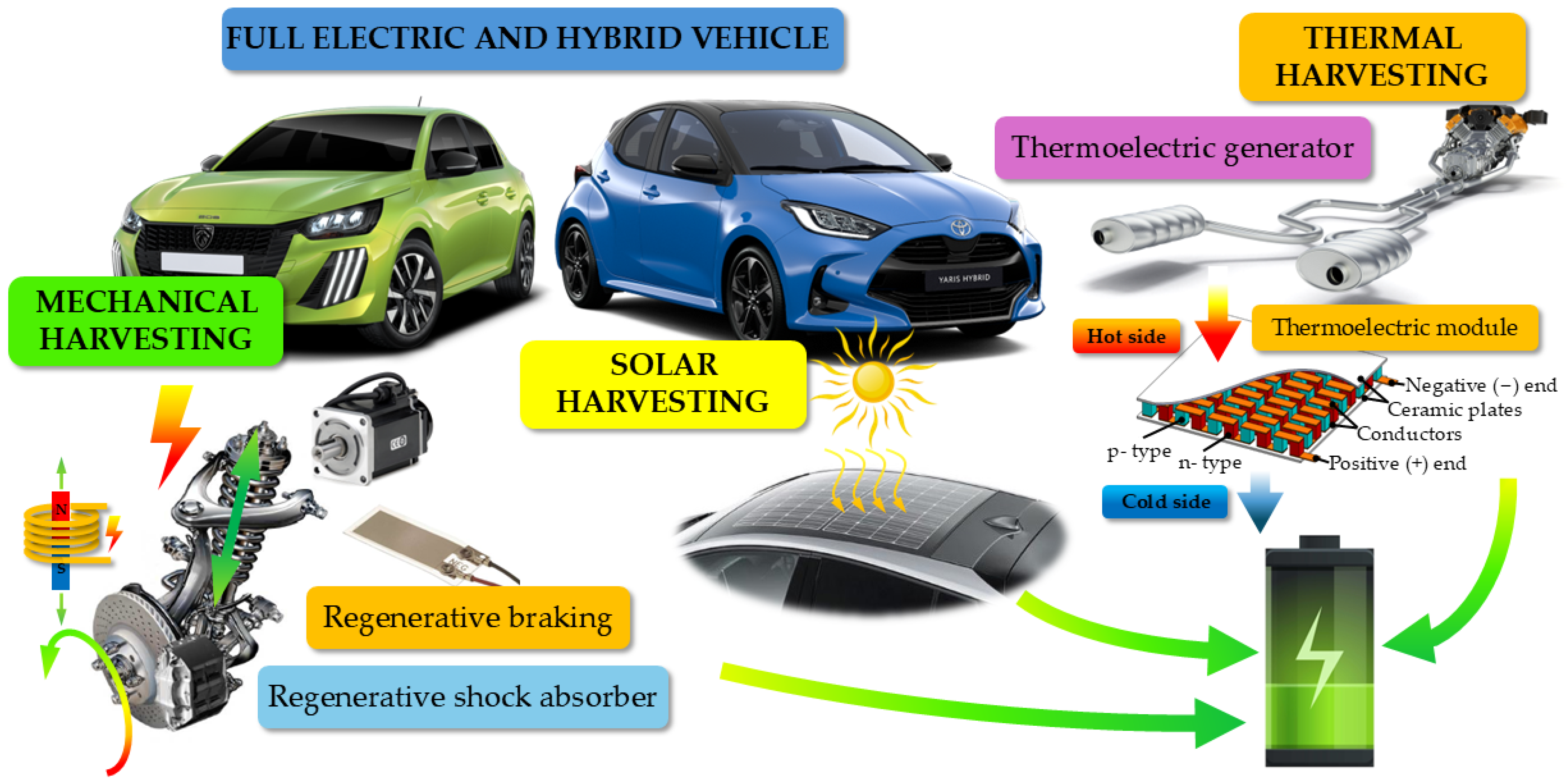
1. Introduction
- ➢
- Mechanical harvesting: various harvesting methodologies that exploit vehicle vibrations to recover electrical energy are presented, placing particular attention on regenerative suspensions and piezoelectric harvesting and presenting innovative solutions with excellent performance (Section 2).
- ➢
- Thermal harvesting: some harvesting solutions have been reported that can convert heat waste from ICEs into electrical energy to power the battery or small devices. Energy recovery solutions that exploit the organic Rankine cycle by recovering the heat produced by the ICE are also presented (Section 3).
- ➢
- Hybrid and environmental harvesting (solar–wind): an overview of solutions capable of simultaneously exploiting a vehicle’s mechanical and thermal energy source is provided. In addition, some harvesting solutions that exploit solar and wind energy are comprehensively described (Section 4).
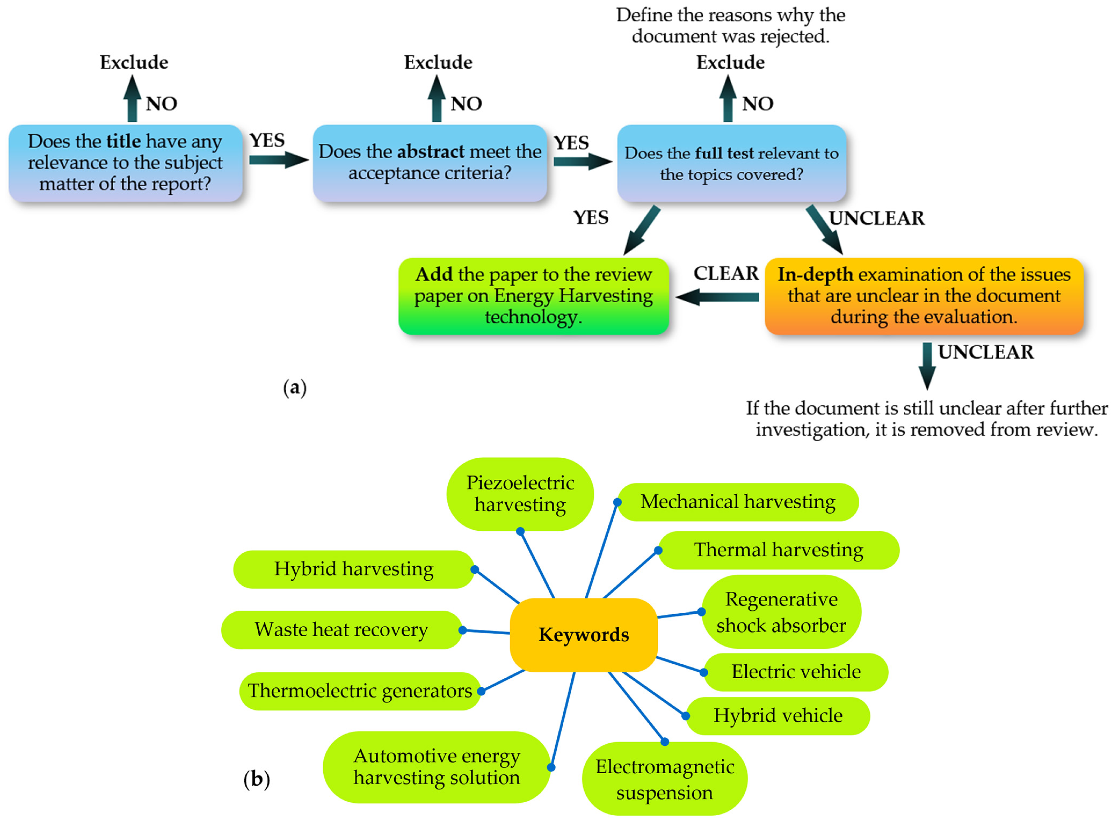
Selection Method of the Analyzed Articles Based on PRISMA Methodologies
2. Electromechanical Solutions for Mechanical Energy Harvesting to Power Auxiliary Devices and Batteries
2.1. Electromechanical Energy Harvesting Applications
- ➢
- Energy harvesting using electric generators
- ➢
- Energy harvesting using electromagnetic systems
- ➢
- Energy harvesting through hydraulic systems
2.2. Piezoelectric Energy Harvesting Applications
- ➢
- Electromechanical/piezoelectric hybrid energy harvesting solutions
- ➢
- Investigation of materials for piezoelectric devices
- ➢
- Piezoelectric ceramics are mechanically robust and can withstand high static stresses, promote the accumulation of electrical charges, increase the sensitivity of devices, and convert mechanical energy into electrical energy with high efficiency [53,54]. The most common piezoelectric ceramics are based on complex oxides, such as PZT (lead zirconate titanate, Pb(Zr,Ti)O3), thanks to high piezoelectric efficiency and the possibility of being polarized to improve performance [15]; however, because of the lead, it is toxic. BaTiO3 (barium titanate) is less widely used than PZT and in less demanding applications. KNN (potassium sodium niobate, K0.5Na0.5NbO3) is an ecological alternative to PZT since it is lead-free. As they are made of ceramic materials, they are fragile and can break under high mechanical stress. Finally, their piezoelectric properties can vary with temperature, limiting some applications.
- ➢
- Polymer-based piezoelectric materials are more flexible and lightweight and can be bent and shaped, which is ideal for wearable devices or for applying to irregular surfaces [55]. Unlike ceramics, they are not brittle and can withstand greater loads without breaking. They have high chemical stability and corrosion resistance but produce a lower electric charge than ceramic materials with the same deformation level and have lower thermal stability. The most common polymer-based piezo-materials are PVDF (polyvinylidene fluoride (C2H2F2)n), which has good piezoelectricity and chemical stability [42,44], PVDF copolymers (PVDF-TrFE), which have better piezoelectricity than pure PVDF, and polymers loaded with piezoelectric ceramic nanoparticles (PZT and BaTiO3) [56].
- ➢
- Monocrystalline piezoelectric materials have a highly ordered and continuous crystalline structure without the grain boundaries or defects typical of polycrystalline ceramics, giving them superior properties compared to ceramics and polymers. These materials have a very high piezoelectric coefficient, high thermal and chemical stability, and greater electromechanical coupling. On the other hand, they are more difficult to produce, are more fragile than polycrystalline materials, and are expensive [57].
- ➢
- Piezoelectric composite materials are engineered materials combining the properties of traditional piezo-materials (ceramic or polymeric) with those of a support matrix (often polymer), optimizing electromechanical properties for specific applications [58].
2.3. Comparative Analysis and Limitations Related to Energy Harvesting Applications Using Mechanical Energy
- ➢
- Discussion of limitations related to mechanical energy-based harvesting applications
3. Energy Harvesting Solutions That Exploit the Wasted Thermal Energy in Vehicles
- The temperature difference;
- The materials used in the generator, which must feature good thermoelectric properties, such as a high Seebeck coefficient and low thermal conductivity;
- Operating conditions, which must be stable to avoid fluctuations in power production.
3.1. Energy Harvesting Using Different Propulsion Systems
- ➢
- Vehicles with an Internal Combustion Engine
- ➢
- Electric and hydrogen vehicles
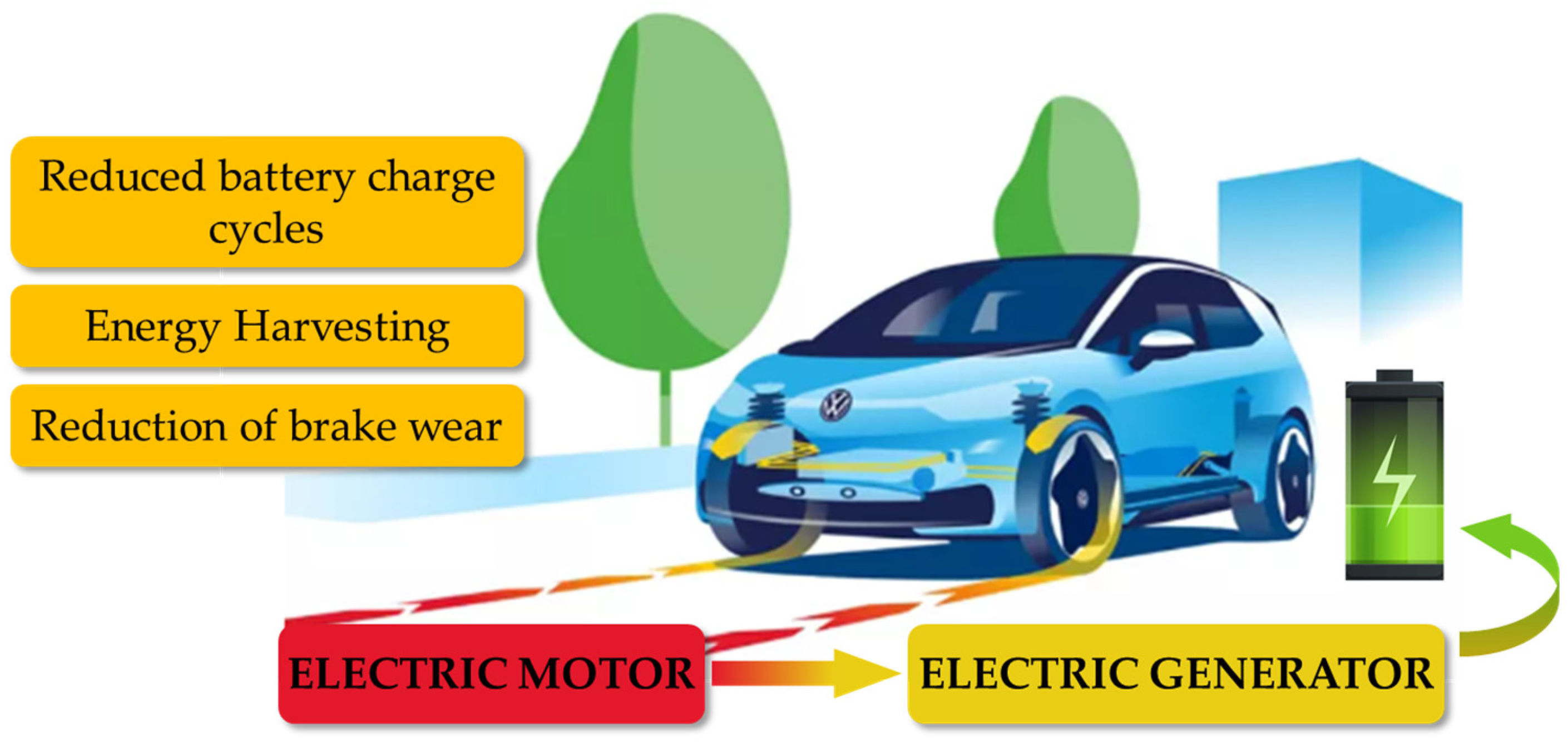
3.2. Energy Recovery from Braking Systems
3.3. Comparative Analysis and Limitations Related to Energy Harvesting Applications Using Thermal Energy
- ➢
- Discussion of limitations related to thermal-energy-based harvesting applications
4. Hybrid, Solar, and Wind Energy Harvesting Systems
4.1. Hybrid Harvesting Systems
4.2. Solar Harvesting Systems
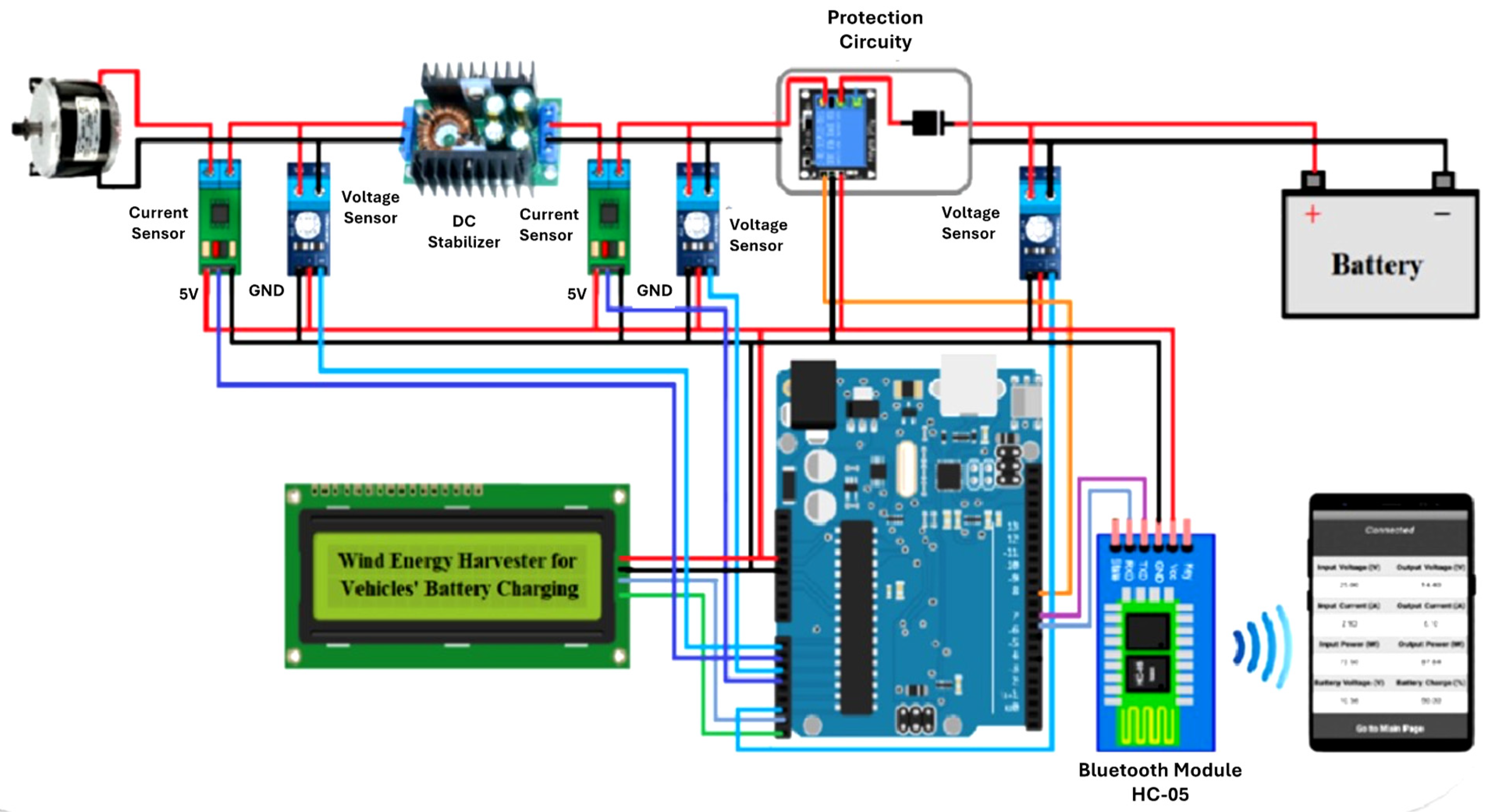
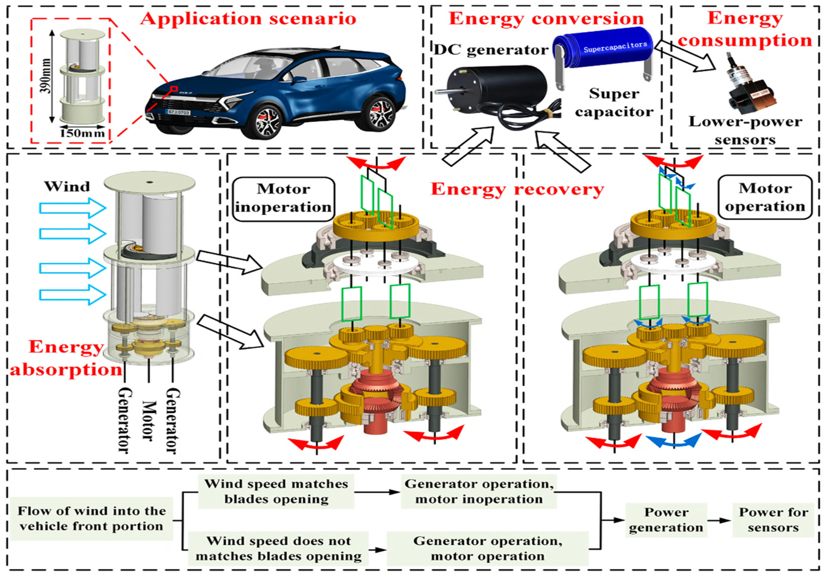
4.3. Wind Harvesting Systems
4.4. Comparative Analysis and Limitations Related to Energy Harvesting Applications from Solar, Wind, and Hybrid Solutions
5. Harvesting Methodologies Implemented by Car Manufacturers in Vehicles
- Regenerative braking, widespread in electric and hybrid vehicles, allows the recovery of kinetic energy during deceleration, reducing fuel consumption and improving battery autonomy;
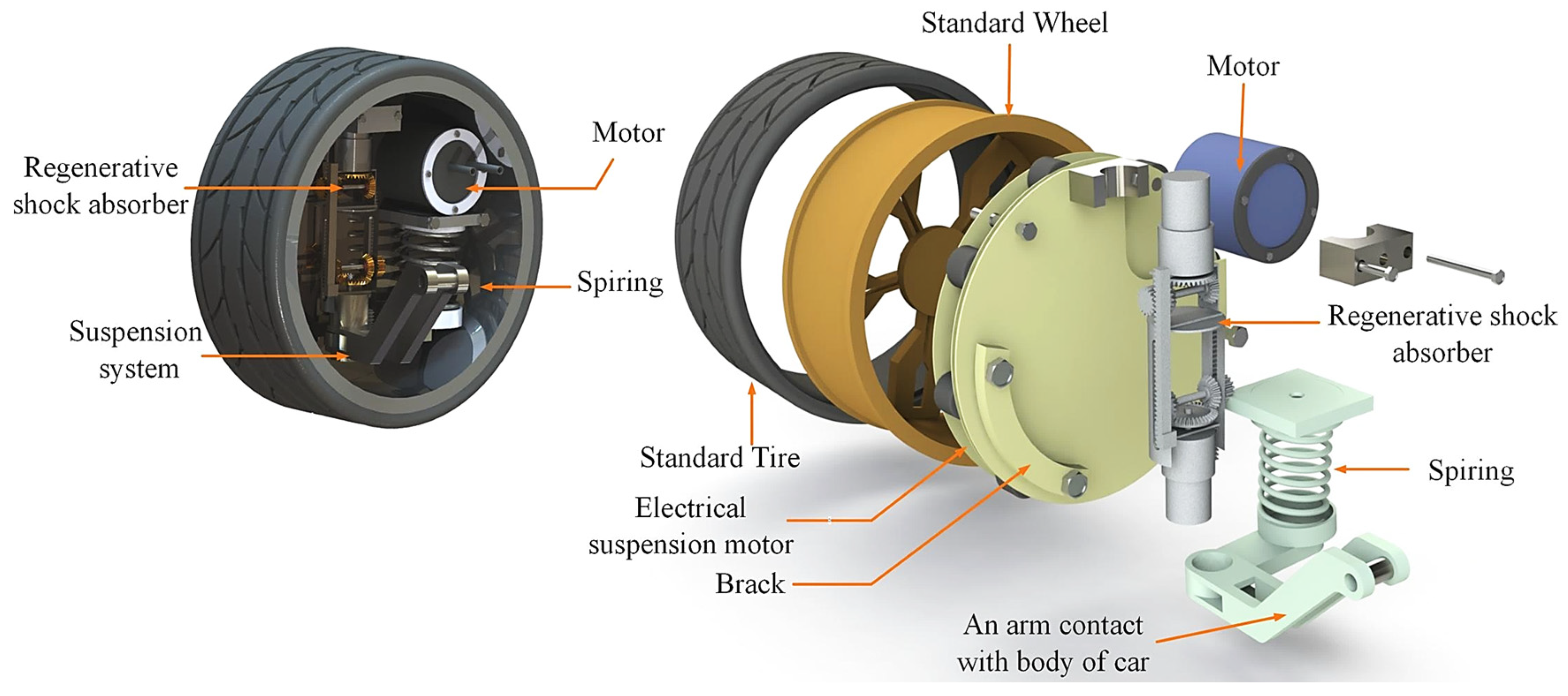
- Suspension harvesting systems use electromagnetic generators to transform suspension vibrations into electrical energy to power onboard electronic components;
- Exhaust heat recovery is mainly used in ICE vehicles. These models use TEG systems made of thermoelectric materials to convert waste heat into electricity;
- Integrated solar panels on the roof to power auxiliary systems such as air conditioning and lighting, reducing the load on the main battery.
5.1. Regenerative Braking and Mechanical Energy Harvesting in Commercial Vehicles
- Tesla uses one-pedal driving technology, moving towards driving with just one pedal. This technology allows for high regeneration when the accelerator is released, reducing the need for mechanical brake use. In the latest models, it is no longer possible to manually adjust the intensity of the regeneration, but the system adapts the braking based on the battery and driving conditions.
- Toyota (hybrid and electric) focuses on a balance between regeneration and mechanical braking. Hybrid models such as the Toyota Prius combine regenerative and mechanical braking for a smooth and natural ride. In these models, regeneration is less aggressive than in pure EVs, which ensures a smoother transition between the two systems (progressive regenerative braking).
- BMW (i3, i4, iX, etc.) has created a system that can select the level of regeneration; in fact, many BMW models offer different regeneration settings, allowing the driver to choose between more aggressive braking or one more similar to a traditional car. In addition, the adaptive range automatically adjusts the intensity of the regenerative braking based on traffic conditions and the road.
- Volkswagen (ID.3, ID.4, etc.) has implemented the B (brake) mode in its vehicles, which increases regeneration and allows for driving like one-pedal driving. The D mode provides lighter regeneration, and the car decelerates more due to inertia.
- Hyundai and Kia (IONIQ 5, EV6, etc.) have implemented the i-Pedal system, which allows driving using only the accelerator pedal, with strong regeneration when released. These vehicles offer multiple regeneration levels, selectable via the paddles on the steering wheel. Finally, the intelligent regenerative braking of these models automatically adapts energy recovery based on the distance from other vehicles and the route type.
- Mercedes-Benz (EQE, EQS, etc.) offers different regeneration modes. The EQ range allows you to select various levels of regenerative braking, up to ‘D Auto’ mode, which automatically manages recovery depending on the traffic. The Mercedes recovery system integrates with advanced driver assistance systems (ADAS) to optimize braking and energy recovery.
- Porsche (Taycan) uses a more discreet regenerative braking system to provide a driving experience similar to a traditional sports car; the regeneration is activated only by operating the brake pedal.
5.2. Thermal Harvesting Systems in Commercial Vehicles
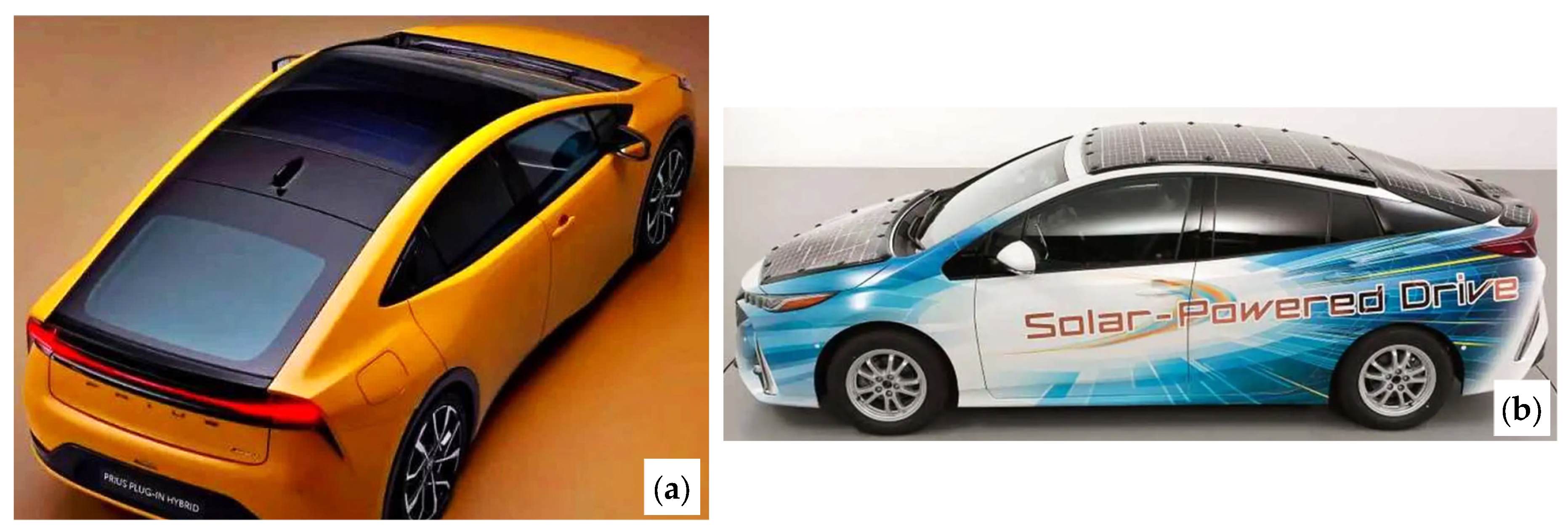
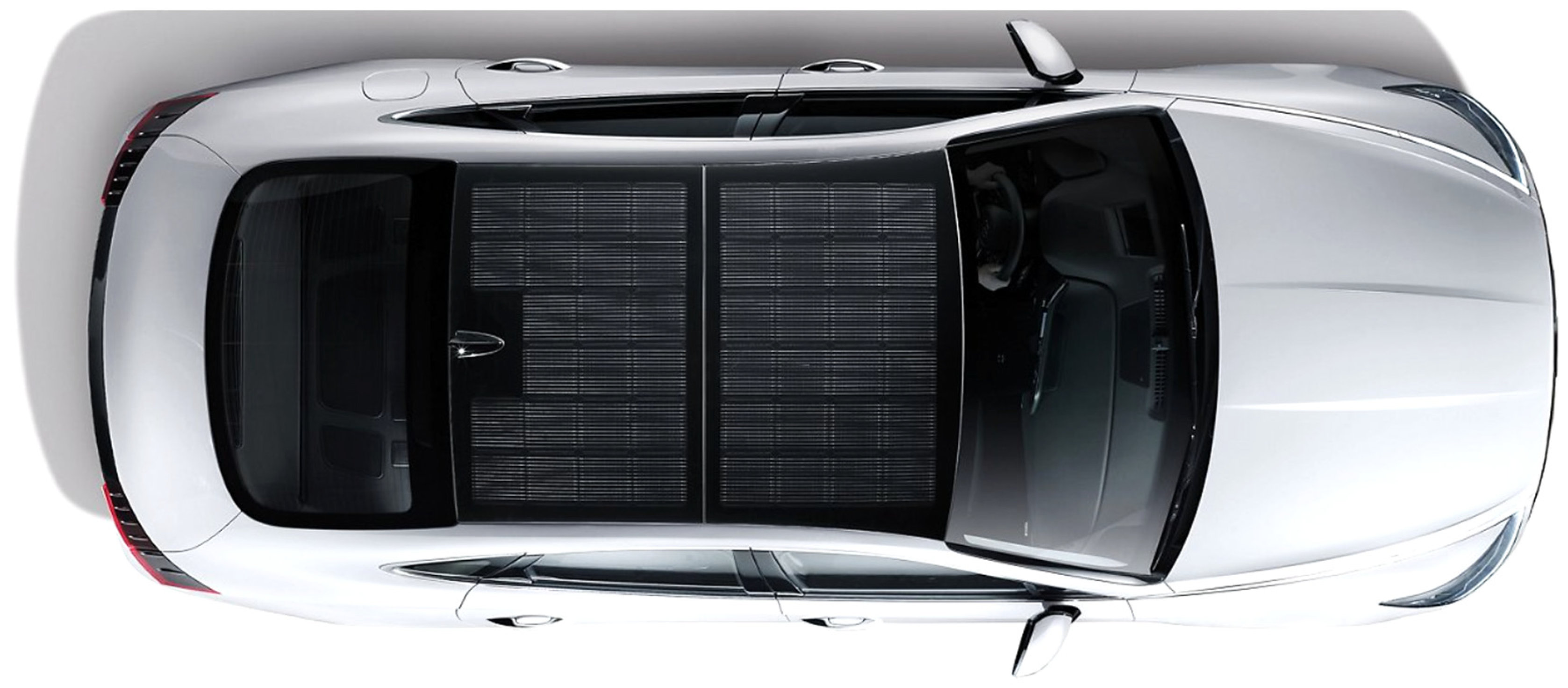
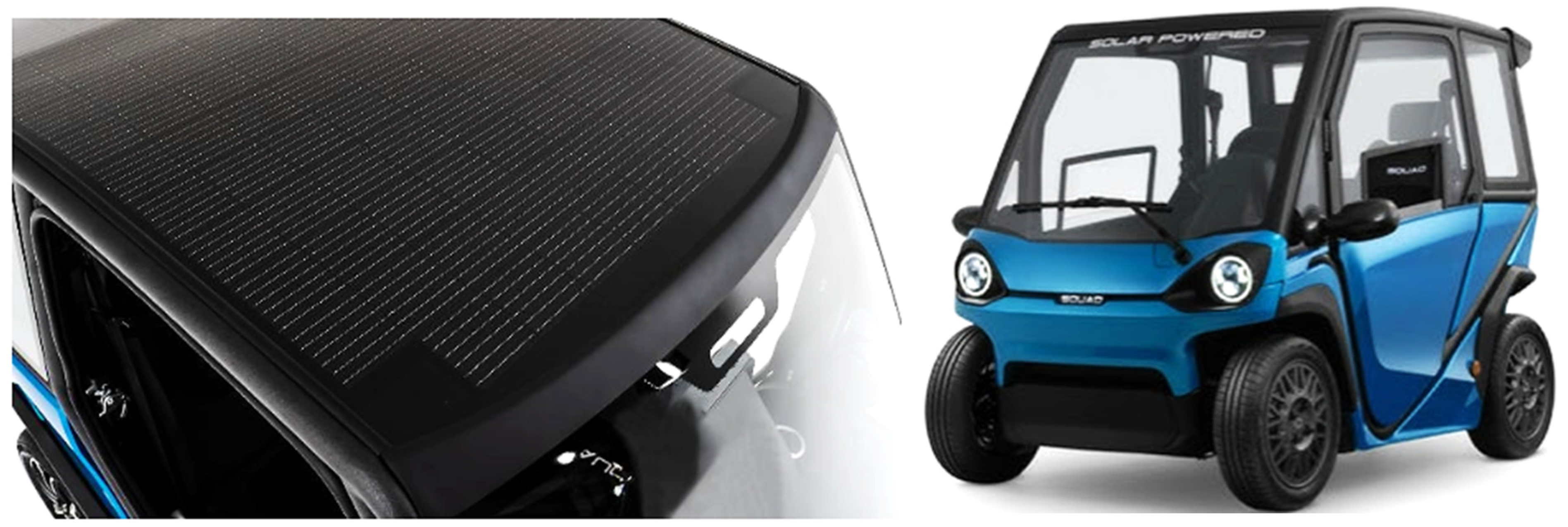
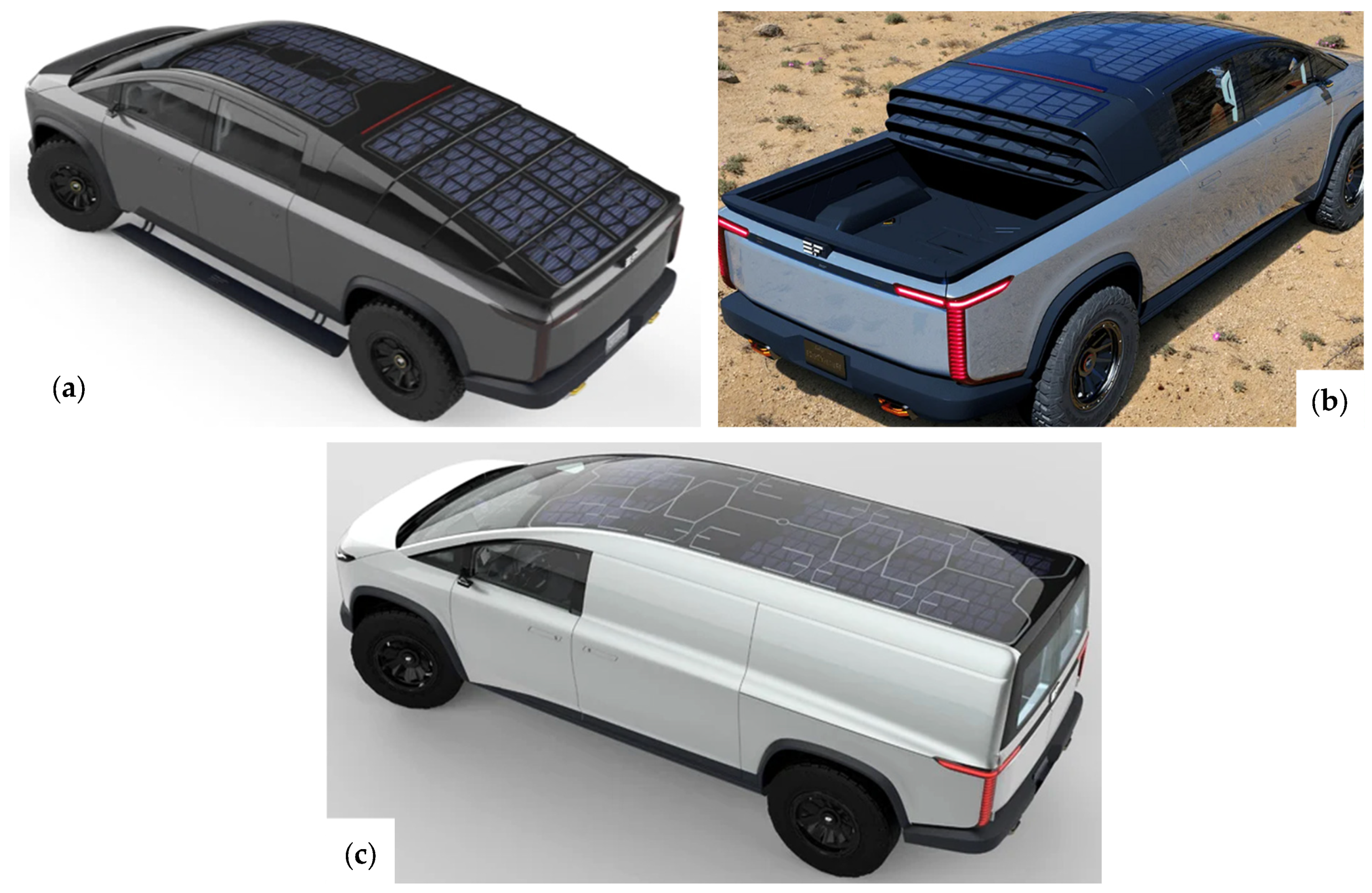
5.3. Solar Harvesting in Commercial Vehicles
6. Thermal, Mechanical, and Environmental (Solar/Wind) Harvesting Technologies in a Horizontal Comparison
- ➢
- Operating principle
- ➢
- Energy efficiency
- ➢
- Cost, scalability, and environmental impact
7. Conclusions
Author Contributions
Funding
Data Availability Statement
Conflicts of Interest
Abbreviations
| Abbreviation | Meaning |
| ICE | Internal Combustion Engine |
| TEG | Thermoelectric Generator |
| ORC | Organic Rankine Cycle |
| EV | Electric Vehicle |
| TSA-AD-ADMM | Two-Stage Accelerated Asynchronous Decentralized Alternating Direction Method of the Multipliers |
| DC | Direct Current |
| AC | Alternating Current |
| RSA | Regenerative Shock Absorber |
| ERSA | Energy Recovery Shock Absorber |
| HVA | Harvesting Vibration Absorber |
| SCB-HESP | Supercapacitor–Lithium Battery Hybrid Energy Storage Paradigm |
| SCB-HESP-RBS | SCB-HESP with Regenerative Shock Absorber |
| MEHS | Magnetic Energy Harvesting Suspension |
| EHSA | Energy Harvesting Shock Absorber |
| IPVA | Inert Pendulum Vibration Absorber |
| SL-MPC | Stochastic Linearization-based Predictive Control |
| S-TENG | Sliding-mode Triboelectric Nanogenerator |
| EP-RSA | Electromagnetic-Pneumatic Regenerative Shock Absorber |
| EMG | Electromagnetic Generator |
| PI | Polyimide |
| HIIRS | Hydraulic Interconnected Integrated Regenerative Suspension |
| PSD | Power Spectral Density |
| IHERS | Inflatable Hydraulic–Electric Regenerative Suspension |
| MEH-RSS | Mechanical–Electric–Hydraulic Regenerative Suspension System |
| HMG | Hydraulic Motor Generator |
| PEH | Piezoelectric Energy Harvester |
| PVDF | Polyvinylidene Fluoride |
| TPU | Thermoplastic Polyurethane |
| IoT | Internet of Things |
| KEH | Kinetic Energy Harvesting |
| FPEH | Flutter Piezoelectric Energy Harvester |
| EVEH | Electromagnetic Vibration Energy Harvester |
| PZT | Lead Zirconate Titanate |
| WHR | Waste Heat Recovery |
| BTE | Brake Thermal Efficiency |
| EGHR | Exhaust Gas Heat Recovery |
| HE | Heat Exchanger |
| WLTC | Worldwide Harmonized Light Vehicles Test Cycle |
| TD | Temperature Difference |
| AEATEG | Automotive Exhaust Annular Thermoelectric Generator |
| AEFTEG | Automotive Exhaust Flat-plate Thermoelectric Generator |
| HTKC | High-Temperature Kalina Cycle |
| IAE-FTEG | Innovative Automobile Exhaust Flexible Thermoelectric Generator |
| ATEG | Annular Thermoelectric Generator |
| ATEM | Annular Thermoelectric Module |
| HEV | Hybrid Electric Vehicle |
| ISG | Integrated Starter and Generator |
| AETEG | Automobile Exhaust Thermoelectric Generator |
| MPC | Model Predictive Control |
| DP | Dynamic Programming |
| SUV | Sport Utility Vehicle |
| AUTEG | Automotive Thermoelectric Generator |
| TEM | Thermoelectric Module |
| TTEG | Tubular Thermoelectric Generator |
| FTEG | Flat-plate Thermoelectric Generator |
| ΔT | Temperature difference |
| DRL | Deep Reinforcement Learning |
| EEV | Extended-range Electric Vehicle |
| PEMFC | Proton Exchange Membrane Fuel Cell |
| HICE | Hydrogen Internal Combustion Engine |
| SOFC | Solid Oxide Fuel Cell |
| CFD | Computational Fluid Analysis |
| HDV | Heavy-Duty Vehicle |
| UHI | Urban Heat Island |
| MRAC | Model Reference Adaptive Control |
| DSSCs | Dye-Sensitized Solar Cells |
| CFRP | Carbon Fiber-Reinforced Poly |
| FOPID | Fractional Order PID |
| NPID | Nonlinear PID |
| IoV | Internet of Vehicle |
| SVAWT | Savonius Vertical-Axis Wind Turbine |
| ADAS | Advanced Driver Assistance System |
References
- Greenhouse Gas Emissions from Transport in Europe. Available online: https://www.eea.europa.eu/en/analysis/indicators/greenhouse-gas-emissions-from-transport (accessed on 18 February 2025).
- Hamada, A.T.; Orhan, M.F. An Overview of Regenerative Braking Systems. J. Energy Storage 2022, 52, 105033. [Google Scholar] [CrossRef]
- Cai, S.; Kirtley, J.L.; Lee, C.H.T. Critical Review of Direct-Drive Electrical Machine Systems for Electric and Hybrid Electric Vehicles. IEEE Trans. Energy Convers. 2022, 37, 2657–2668. [Google Scholar] [CrossRef]
- Wang, Y.; Biswas, A.; Rodriguez, R.; Keshavarz-Motamed, Z.; Emadi, A. Hybrid Electric Vehicle Specific Engines: State-of-the-Art Review. Energy Rep. 2022, 8, 832–851. [Google Scholar] [CrossRef]
- Amer, M.; Masri, J.; Dababat, A.; Sajjad, U.; Hamid, K. Electric Vehicles: Battery Technologies, Charging Standards, AI Communications, Challenges, and Future Directions. Energy Convers. Manag. X 2024, 24, 100751. [Google Scholar] [CrossRef]
- Alanazi, F. Electric Vehicles: Benefits, Challenges, and Potential Solutions for Widespread Adaptation. Appl. Sci. 2023, 13, 6016. [Google Scholar] [CrossRef]
- Waseem, M.; Ahmad, M.; Parveen, A.; Suhaib, M. Battery Technologies and Functionality of Battery Management System for EVs: Current Status, Key Challenges, and Future Prospectives. J. Power Sources 2023, 580, 233349. [Google Scholar] [CrossRef]
- Matharu, H.S.; Girase, V.; Pardeshi, D.B.; William, P. Design and Deployment of Hybrid Electric Vehicle. In Proceedings of the 2022 International Conference on Electronics and Renewable Systems (ICEARS), Tuticorin, India, 16–18 March 2022; pp. 331–334. [Google Scholar]
- Bai, S.; Liu, C. Overview of Energy Harvesting and Emission Reduction Technologies in Hybrid Electric Vehicles. Renew. Sustain. Energy Rev. 2021, 147, 111188. [Google Scholar] [CrossRef]
- Mhatre, A.S.; Shukla, P. A Comprehensive Review of Energy Harvesting Technologies for Sustainable Electric Vehicles. Environ. Sci. Pollut. Res. 2024. [Google Scholar] [CrossRef]
- Hosseini, S.M.; Soleymani, M.; Kelouwani, S.; Amamou, A.A. Energy Recovery and Energy Harvesting in Electric and Fuel Cell Vehicles, a Review of Recent Advances. IEEE Access 2023, 11, 83107–83135. [Google Scholar] [CrossRef]
- Bentouba, S.; Zioui, N.; Breuhaus, P.; Bourouis, M. Overview of the Potential of Energy Harvesting Sources in Electric Vehicles. Energies 2023, 16, 5193. [Google Scholar] [CrossRef]
- Salman, W.; Zhang, X.; Li, H.; Wu, X.; Li, N.; Azam, A.; Zhang, Z. A Novel Energy Regenerative Shock Absorber for In-Wheel Motors in Electric Vehicles. Mech. Syst. Signal Process. 2022, 181, 109488. [Google Scholar] [CrossRef]
- Zhou, R.; Yan, M.; Sun, F.; Jin, J.; Li, Q.; Xu, F.; Zhang, M.; Zhang, X.; Nakano, K. Experimental Validations of a Magnetic Energy-Harvesting Suspension and Its Potential Application for Self-Powered Sensing. Energy 2022, 239, 122205. [Google Scholar] [CrossRef]
- Zhang, B.; Zhao, Z.; Li, Y.; Zhang, X.; Li, X.; Hao, D.; Zhang, Z. Design and Analysis of a Piezoelectric Energy Harvesting Shock Absorber for Light Truck Applications. Appl. Energy 2025, 377, 124569. [Google Scholar] [CrossRef]
- Huang, J.; Xu, C.; Ma, N.; Zhou, Q.; Ji, Z.; Jia, C.; Xiao, S.; Wang, P. Intelligent Device for Harvesting the Vibration Energy of the Automobile Exhaust with a Piezoelectric Generator. Micromachines 2023, 14, 491. [Google Scholar] [CrossRef]
- Madaro, F.; Mehdipour, I.; Caricato, A.; Guido, F.; Rizzi, F.; Carlucci, A.P.; De Vittorio, M. Available Energy in Cars’ Exhaust System for IoT Remote Exhaust Gas Sensor and Piezoelectric Harvesting. Energies 2020, 13, 4169. [Google Scholar] [CrossRef]
- Koo, B.-G.; Shin, D.-J.; Lim, D.-H.; Kim, M.-S.; Kim, I.-S.; Jeong, S.-J. Properties of Car-Embedded Vibrating Type Piezoelectric Harvesting System. Appl. Sci. 2021, 11, 7449. [Google Scholar] [CrossRef]
- Hazeri, S.; Mulligan, C.N. Energy Harvesting by Piezo-Tires and Their Life Cycle Assessment. AIP Adv. 2022, 12, 065112. [Google Scholar] [CrossRef]
- Dadi, P.S.; R, M.; Rajkumar, K.; R, S. Enhance Energy Efficiency Based Automobile Wheels by Using Piezoelectric Energy Harvesting Technology and Sustainable Power Generation. In Proceedings of the 2024 2nd International Conference on Networking & Communications (ICNWC), Chennai, India, 2–4 April 2024; IEEE: New York, NY, USA, 2024; pp. 1–9. [Google Scholar] [CrossRef]
- Liu, C.; Wang, Q.; Wang, Y.; Wang, Z.; Han, X.; Zhou, Q.; He, Z.; Yin, T. Automobile Exhaust Flexible Thermoelectric Harvester Enabled by Liquid Metal-Based Heatsink. Energy Convers. Manag. 2024, 316, 118826. [Google Scholar] [CrossRef]
- Sok, R.; Kusaka, J. Development and Validation of Thermal Performances in a Novel Thermoelectric Generator Model for Automotive Waste Heat Recovery Systems. Int. J. Heat Mass Transf. 2023, 202, 123718. [Google Scholar] [CrossRef]
- Zhai, X.; Li, Z.; Li, Z.; Xue, Y.; Chang, X.; Su, J.; Jin, X.; Wang, P.; Sun, H. Risk-Averse Energy Management for Integrated Electricity and Heat Systems Considering Building Heating Vertical Imbalance: An Asynchronous Decentralized Approach. Appl. Energy 2025, 383, 125271. [Google Scholar] [CrossRef]
- Zhang, H.; Li, Z.; Xue, Y.; Chang, X.; Su, J.; Wang, P.; Guo, Q.; Sun, H. A Stochastic Bi-Level Optimal Allocation Approach of Intelligent Buildings Considering Energy Storage Sharing Services. IEEE Trans. Consum. Electron. 2024, 70, 5142–5153. [Google Scholar] [CrossRef]
- Page, M.J.; McKenzie, J.E.; Bossuyt, P.M.; Boutron, I.; Hoffmann, T.C.; Mulrow, C.D.; Shamseer, L.; Tetzlaff, J.M.; Akl, E.A.; Brennan, S.E.; et al. The PRISMA 2020 Statement: An Updated Guideline for Reporting Systematic Reviews. BMJ 2021, 372, n71. [Google Scholar] [CrossRef] [PubMed]
- Page, M.J.; Moher, D.; Bossuyt, P.M.; Boutron, I.; Hoffmann, T.C.; Mulrow, C.D.; Shamseer, L.; Tetzlaff, J.M.; Akl, E.A.; Brennan, S.E.; et al. PRISMA 2020 Explanation and Elaboration: Updated Guidance and Exemplars for Reporting Systematic Reviews. BMJ 2021, 372, n160. [Google Scholar] [CrossRef] [PubMed]
- Ali, A.; Ahmed, A.; Ali, M.; Azam, A.; Wu, X.; Zhang, Z.; Yuan, Y. A Review of Energy Harvesting from Regenerative Shock Absorber from 2000 to 2021: Advancements, Emerging Applications, and Technical Challenges. Environ. Sci. Pollut. Res. 2023, 30, 5371–5406. [Google Scholar] [CrossRef]
- Abdelkareem, M.A.A.; Eldaly, A.B.M.; Kamal Ahmed Ali, M.; Youssef, I.M.; Xu, L. Monte Carlo Sensitivity Analysis of Vehicle Suspension Energy Harvesting in Frequency Domain. J. Adv. Res. 2020, 24, 53–67. [Google Scholar] [CrossRef]
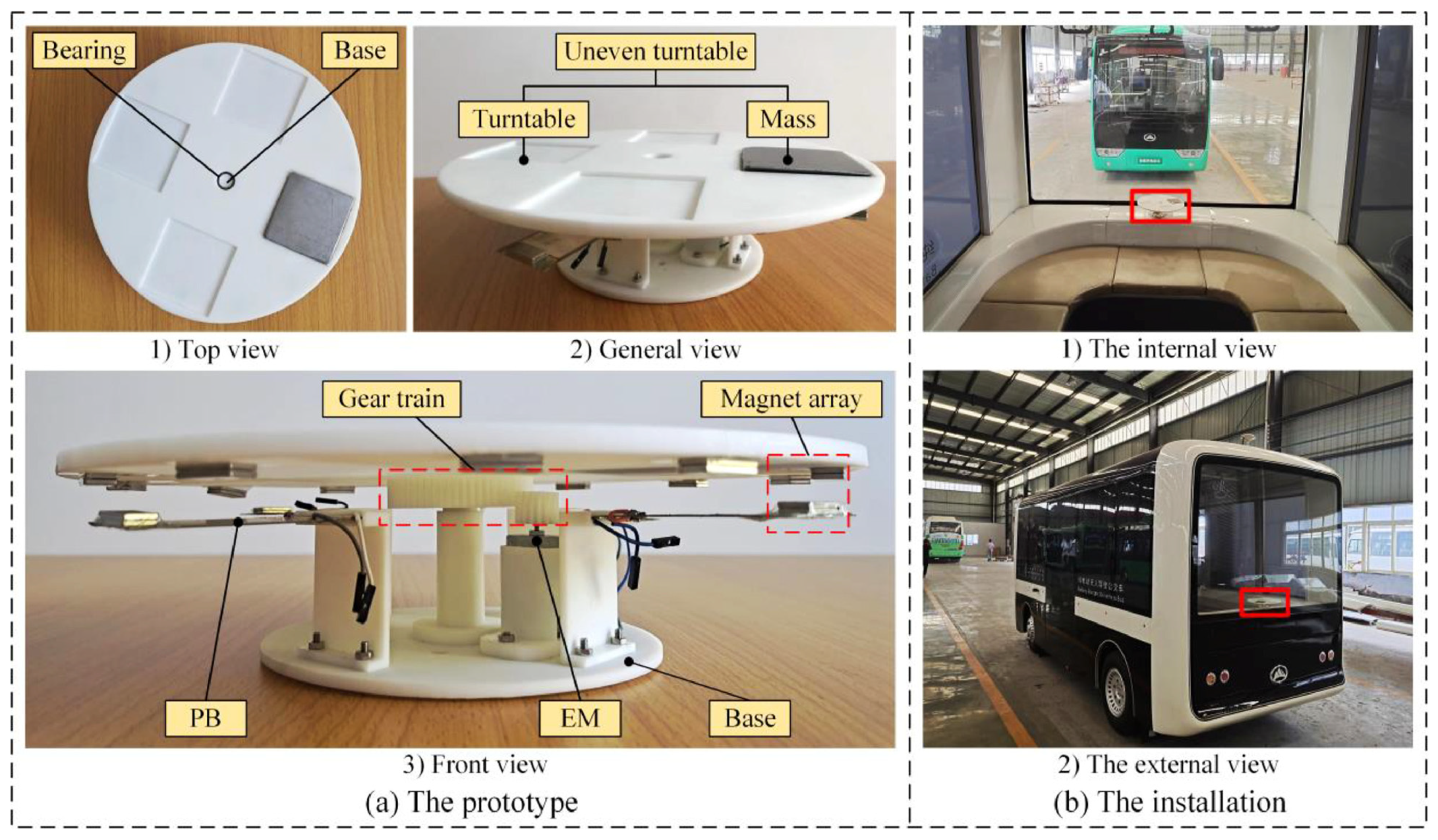
- Abdelrahman, M.; Liu, G.; Fan, C.; Zhang, Z.; Ali, A.; Li, H.; Azam, A.; Cao, H.; Mohamed, A.A. Energy Regenerative Shock Absorber Based on a Slotted Link Conversion Mechanism for Application in the Electrical Bus to Power the Low Wattages Devices. Appl. Energy 2023, 347, 121409. [Google Scholar] [CrossRef]
- Techalimsakul, P.; Sawetmethikul, P. Efficiency Analysis of Hybrid Extreme Regenerative with Supercapacitor Battery and Harvesting Vibration Absorber System for Electric Vehicles Driven by Permanent Magnet Synchronous Motor 30 kW. World Electr. Veh. J. 2024, 15, 214. [Google Scholar] [CrossRef]
- Li, H.; Zheng, P.; Zhang, T.; Zou, Y.; Pan, Y.; Zhang, Z.; Azam, A. A High-Efficiency Energy Regenerative Shock Absorber for Powering Auxiliary Devices of New Energy Driverless Buses. Appl. Energy 2021, 295, 117020. [Google Scholar] [CrossRef]
- Wang, Z.; Zhang, T.; Zhang, Z.; Yuan, Y.; Liu, Y. A High-Efficiency Regenerative Shock Absorber Considering Twin Ball Screws Transmissions for Application in Range-Extended Electric Vehicles. Energy Built Environ. 2020, 1, 36–49. [Google Scholar] [CrossRef]
- Hajidavalloo, M.R.; Cosner, J.; Li, Z.; Tai, W.-C.; Song, Z. Simultaneous Suspension Control and Energy Harvesting Through Novel Design and Control of a New Nonlinear Energy Harvesting Shock Absorber. IEEE Trans. Veh. Technol. 2022, 71, 6073–6087. [Google Scholar] [CrossRef]
- Jiang, W.; Song, Y.; Xu, Y.; Zhou, R.; Sun, F.; Zhang, X. Energy-Harvesting Characteristics of a Dual-Mode Magnetic Suspension for Vehicles: Analysis and Experimental Verification. Actuators 2022, 11, 363. [Google Scholar] [CrossRef]
- Hu, Y.; Wang, X.; Qin, Y.; Li, Z.; Wang, C.; Wu, H. A Robust Hybrid Generator for Harvesting Vehicle Suspension Vibration Energy from Random Road Excitation. Appl. Energy 2022, 309, 118506. [Google Scholar] [CrossRef]
- Niu, S.; Liu, Y.; Wang, S.; Lin, L.; Zhou, Y.S.; Hu, Y.; Wang, Z.L. Theory of Sliding-Mode Triboelectric Nanogenerators. Adv. Mater. 2013, 25, 6184–6193. [Google Scholar] [CrossRef] [PubMed]
- Song, J.; Zong, R.; Li, Y.; Gao, Y.; Chen, Z.; Qi, L.; Zhang, Z. An Electromagnetic-Pneumatic Hybrid Regenerative Shock Absorber for Extended Range of Space Exploration Vehicles. Mech. Syst. Signal Process. 2024, 210, 111161. [Google Scholar] [CrossRef]
- Zou, J.; Guo, S.; Guo, X.; Xu, L.; Wu, Y.; Pan, Y. Hydraulic Integrated Interconnected Regenerative Suspension: Modeling and Mode-Decoupling Analysis. Mech. Syst. Signal Process. 2022, 172, 108998. [Google Scholar] [CrossRef]
- Zhang, W.; Wang, G.; Guo, Y. Research on Damping and Energy Recovery Characteristics of a Novel Mechanical-Electrical-Hydraulic Regenerative Suspension System. Energy 2023, 271, 127022. [Google Scholar] [CrossRef]
- Zhang, B.; Luo, M.; Tan, C.A. Ride Comfort and Energy Harvesting of Inflatable Hydraulic-Electric Regenerative Suspension System for Heavy-Duty Vehicles. J. Mech. Sci. Technol. 2024, 38, 2277–2289. [Google Scholar] [CrossRef]
- Ghazanfarian, J.; Mohammadi, M.M.; Uchino, K. Piezoelectric Energy Harvesting: A Systematic Review of Reviews. Actuators 2021, 10, 312. [Google Scholar] [CrossRef]
- Yu, G.; He, L.; Wang, H.; Sun, L.; Zhang, Z.; Cheng, G. Research of Rotating Piezoelectric Energy Harvester for Automotive Motion. Renew. Energy 2023, 211, 484–493. [Google Scholar] [CrossRef]
- Li, Y.; Wang, R.; Wan, Z.; Chen, M.; Liang, G. Effects of Mechanical and Electrical Topologies on Piezoelectric Stacked Energy Harvesting in Vehicle Suspensions. Int. J. Energy Res. 2024, 2024, 6680018. [Google Scholar] [CrossRef]
- Ikbal, M.; Rizal, M.; Ali, N.; Putra, T.E. Design and Experimental Study of Piezoelectric Energy Harvester Integrated in Rotating Vehicle Tire Using End-Cap System. Results Eng. 2025, 25, 104195. [Google Scholar] [CrossRef]
- Devi, K.S.; Vishnuraj, C.; Thaufiq Parvez, I.S.; Sukirtha Veena, K.; Swathi, S. Generate Electricity for Automobiles Using Piezoelectric Sensors—Using IoT. In Proceedings of the 2024 3rd International Conference on Automation, Computing & Renewable Systems, Pudukkottai, India, 4–6 December 2024; IEEE: New York, NY, USA, 2025; pp. 447–452. [Google Scholar] [CrossRef]
- Alhumaid, S.; Hess, D.; Guldiken, R. A Noncontact Magneto–Piezo Harvester-Based Vehicle Regenerative Suspension System: An Experimental Study. Energies 2022, 15, 4476. [Google Scholar] [CrossRef]
- Zhao, Z.; Zhang, B.; Li, Y.; Bao, C.; Wang, T. A Novel Piezoelectric Energy Harvester of Noncontact Magnetic Force for a Vehicle Suspension System. Energy Sci. Eng. 2023, 11, 1133–1147. [Google Scholar] [CrossRef]
- Morad, H.; Nikzad, A.; Keynia, F. Generation of Electrical Energy through Vehicle Impact in Shock Absorbers Using Layered Piezoelectric Plates. In Proceedings of the 2024 19th Iranian Conference on Intelligent Systems (ICIS), Sirjan, Iran, 23–24 October 2024; IEEE: New York, NY, USA, 2025; pp. 174–177. [Google Scholar] [CrossRef]
- Tang, M.; Cao, H.; Kong, L.; Azam, A.; Luo, D.; Pan, Y.; Zhang, Z. A Hybrid Kinetic Energy Harvester for Applications in Electric Driverless Buses. Int. J. Mech. Sci. 2022, 223, 107317. [Google Scholar] [CrossRef]
- Li, Z.; Li, X.; Liu, B.; Wang, J. Influence of Vehicle Body Vibration Induced by Road Excitation on the Performance of a Vehicle-Mounted Piezoelectric-Electromagnetic Hybrid Energy Harvester. Smart Mater. Struct. 2021, 30, 055019. [Google Scholar] [CrossRef]
- Sekhar, M.C.; Veena, E.; Kumar, N.S.; Naidu, K.C.B.; Mallikarjuna, A.; Basha, D.B. A Review on Piezoelectric Materials and Their Applications. Cryst. Res. Technol. 2023, 58, 2200130. [Google Scholar] [CrossRef]
- Yang, C.; Ji, J.; Lv, Y.; Li, Z.; Luo, D. Application of Piezoelectric Material and Devices in Bone Regeneration. Nanomaterials 2022, 12, 4386. [Google Scholar] [CrossRef]
- Ju, M.; Dou, Z.; Li, J.-W.; Qiu, X.; Shen, B.; Zhang, D.; Yao, F.-Z.; Gong, W.; Wang, K. Piezoelectric Materials and Sensors for Structural Health Monitoring: Fundamental Aspects, Current Status, and Future Perspectives. Sensors 2023, 23, 543. [Google Scholar] [CrossRef]
- Dai, Y.; Li, D.; Wang, D. Review on the Nonlinear Modeling of Hysteresis in Piezoelectric Ceramic Actuators. Actuators 2023, 12, 442. [Google Scholar] [CrossRef]
- Ansari, M.A.; Somdee, P. Piezoelectric Polymeric Foams as Flexible Energy Harvesters: A Review. Adv. Energy Sustain. Res. 2022, 3, 2200063. [Google Scholar] [CrossRef]
- Chang, S.-M.; Hur, S.; Park, J.; Lee, D.-G.; Shin, J.; Kim, H.S.; Song, S.E.; Baik, J.M.; Kim, M.; Song, H.-C.; et al. Optimization of Piezoelectric Polymer Composites and 3D Printing Parameters for Flexible Tactile Sensors. Addit. Manuf. 2023, 67, 103470. [Google Scholar] [CrossRef]
- Katsumata, Y.; Yoshida, S.; Tanaka, S. Fabrication of Monocrystalline-Based Composite PZT Thin Film with Polycrystalline Crack Stopper Structure. In Proceedings of the 2022 IEEE 35th International Conference on Micro Electro Mechanical Systems Conference (MEMS), Tokyo, Japan, 9–13 January 2022; IEEE: New York, NY, USA, 2022; pp. 543–546. [Google Scholar] [CrossRef]
- Zhang, X.; Xia, W.; Liu, J.; Zhao, M.; Li, M.; Xing, J. PVDF-Based and Its Copolymer-Based Piezoelectric Composites: Preparation Methods and Applications. J. Electron. Mater. 2022, 51, 5528–5549. [Google Scholar] [CrossRef]
- Rijpkema, J.; Erlandsson, O.; Andersson, S.B.; Munch, K. Exhaust Waste Heat Recovery from a Heavy-Duty Truck Engine: Experiments and Simulations. Energy 2022, 238, 121698. [Google Scholar] [CrossRef]
- Sok, R.; Kusaka, J. Experimental and Modeling Analysis on Thermoelectric Heat Recovery to Maximize the Performance of Next-Generation Diesel Engines Dedicated for Future Electrified Powertrains. Appl. Therm. Eng. 2023, 219, 119530. [Google Scholar] [CrossRef]
- Kumar, V.; Dadam, S.R.; Zhu, D.; Mehring, J. Fuel-Economy Performance Analysis with Exhaust Heat Recovery System on Gasoline Engine. SAE Int. J. Engines 2022, 15, 825–848. [Google Scholar] [CrossRef]
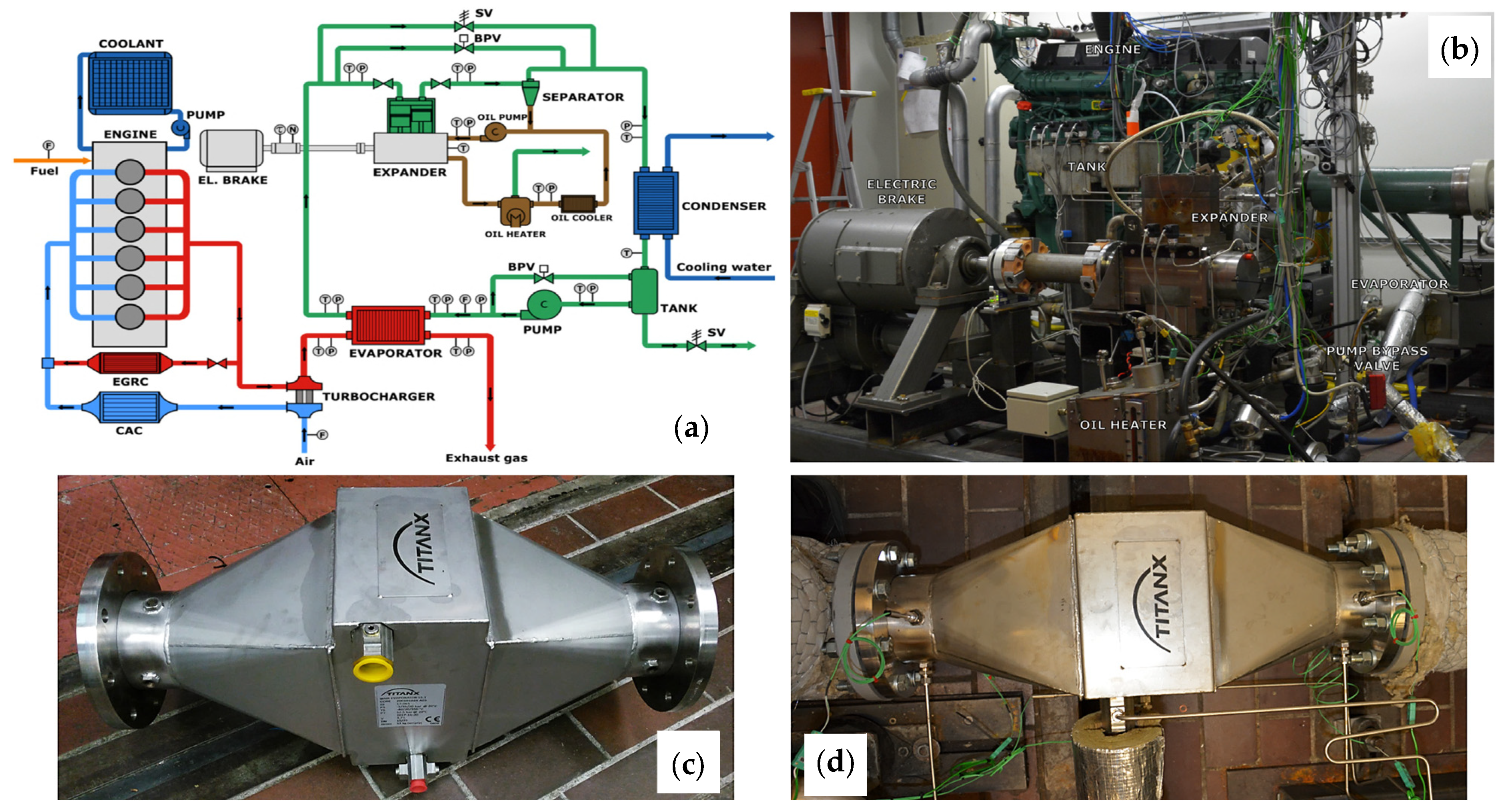
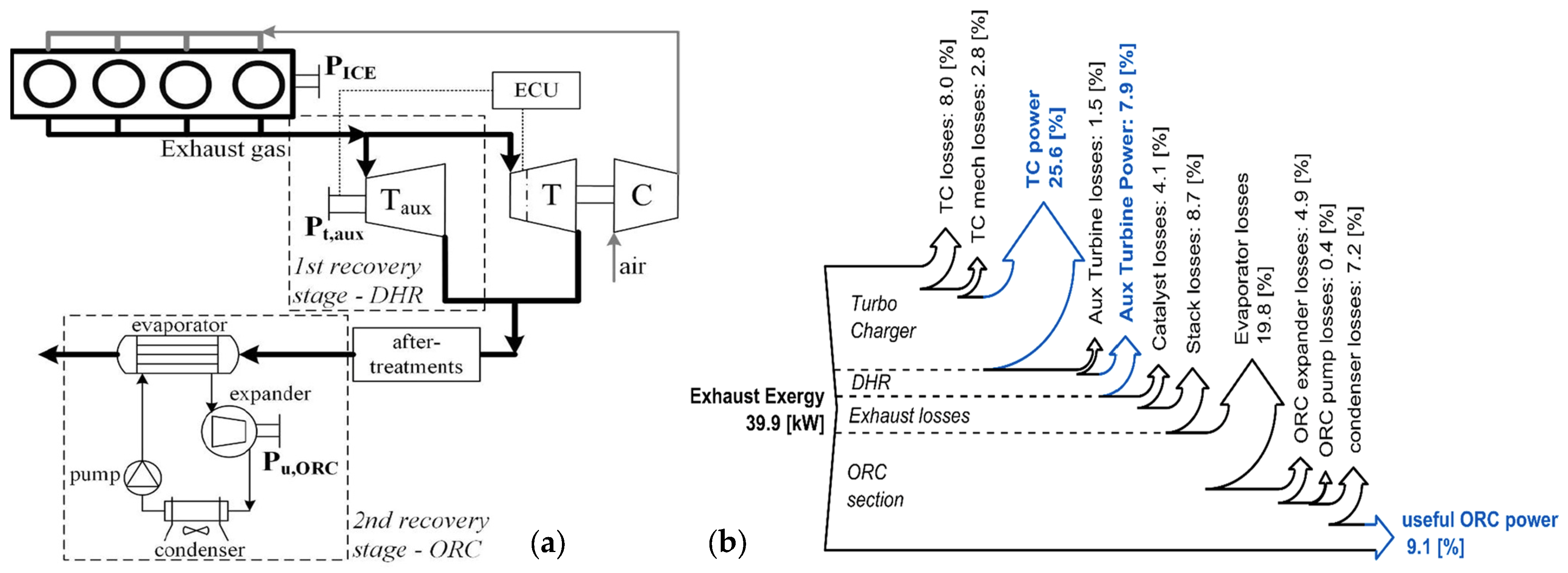
- Di Battista, D.; Di Bartolomeo, M.; Cipollone, R. Full Energy Recovery from Exhaust Gases in a Turbocharged Diesel Engine. Energy Convers. Manag. 2022, 271, 116280. [Google Scholar] [CrossRef]
- Khayum, N.; Anbarasu, S.; Murugan, S. Optimizing Waste Heat Recovery in a Dual-Fuel Diesel Engine through Thermoelectric Generation and Heat Pipe Integration. J. Renew. Sustain. Energy 2024, 16, 063103. [Google Scholar] [CrossRef]
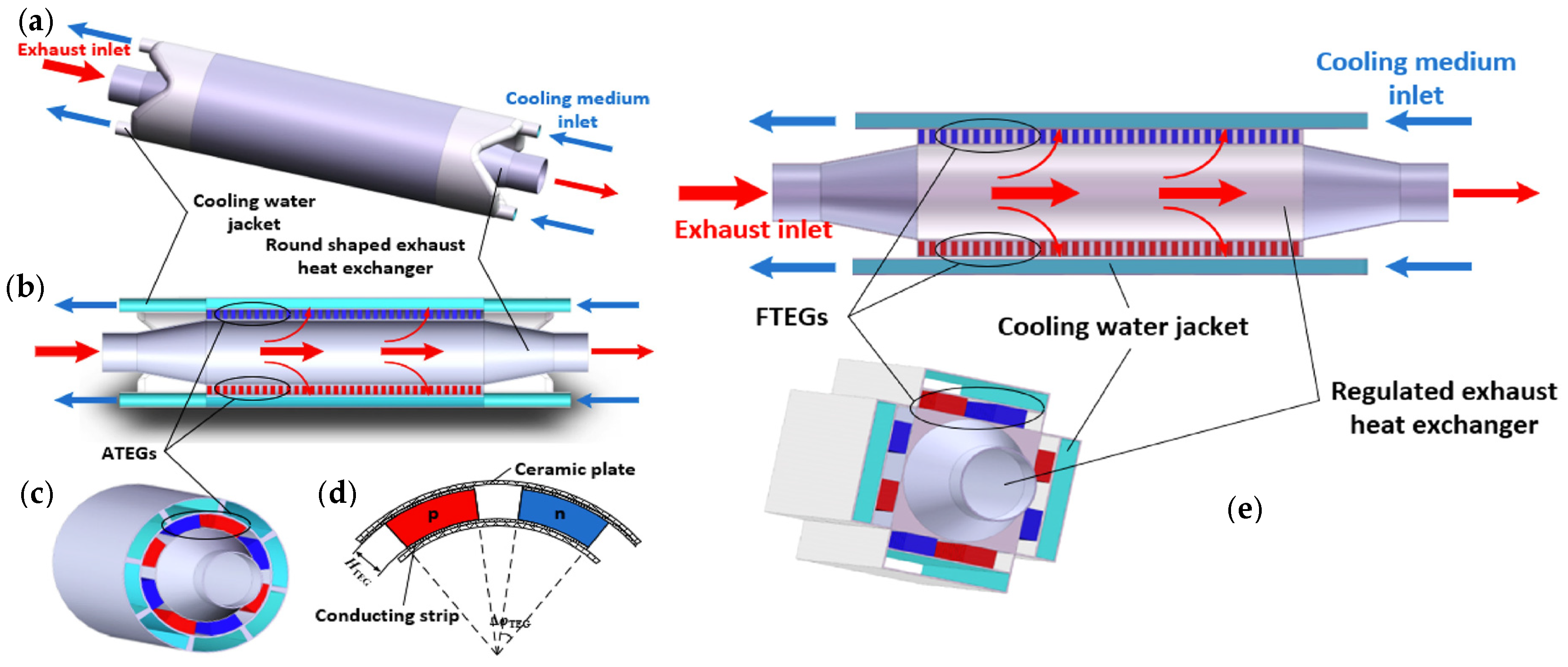
- Huang, B.; Shen, Z.-G. Performance Assessment of Annular Thermoelectric Generators for Automobile Exhaust Waste Heat Recovery. Energy 2022, 246, 123375. [Google Scholar] [CrossRef]
- Sharma, G.; Kumar, J.; Sharma, S.; Singh, G.; Singh, J.; Sharma, A.; Chohan, J.S.; Kumar, R.; Obaid, A.J. Performance of Diesel Engine Having Waste Heat Recovery System Fixed on Stainless Steel Made Exhaust Gas Pipe. Mater. Today Proc. 2022, 48, 1141–1146. [Google Scholar] [CrossRef]
- Roeinfard, N.; Moosavi, A. Thermodynamic Analysis and Optimization of the Organic Rankine and High-Temperature Kalina Cycles for Recovering the Waste Heat of a Bi-Fuel Engine. Fuel 2022, 322, 124174. [Google Scholar] [CrossRef]
- Burnete, N.V.; Mariasiu, F.; Depcik, C.; Barabas, I.; Moldovanu, D. Review of Thermoelectric Generation for Internal Combustion Engine Waste Heat Recovery. Prog. Energy Combust. Sci. 2022, 91, 101009. [Google Scholar] [CrossRef]
- Asaduzzaman, M.; Ali, M.H.; Pratik, N.A.; Lubaba, N. Exhaust Heat Harvesting of Automotive Engine Using Thermoelectric Generation Technology. Energy Convers. Manag. X 2023, 19, 100398. [Google Scholar] [CrossRef]
- Luo, D.; Zhang, H.; Cao, J.; Yan, Y.; Cao, B. Innovative Design of an Annular Thermoelectric Generator for Enhanced Automotive Waste Heat Recovery. Energy Convers. Manag. 2024, 313, 118584. [Google Scholar] [CrossRef]
- Quan, R.; Liu, D.; Li, X.; Chang, Y.; Wan, H. Performance Evaluation and Energy Management of an Automobile Exhaust Thermoelectric Generator for ISG Mild HEV Application. Appl. Therm. Eng. 2024, 243, 122556. [Google Scholar] [CrossRef]
- Quan, R.; Liu, D.; Li, W.; Feng, Z.; Chang, Y.; Wan, H. The Potential Role of Automotive Thermoelectric Generator to Improve the Fuel Economy of Vehicle. Energy Convers. Manag. 2024, 308, 118421. [Google Scholar] [CrossRef]
- Luo, D.; Yang, S.; Yan, Y.; Cao, J.; Yang, X.; Cao, B. Performance Improvement of the Automotive Thermoelectric Generator System with a Novel Heat Pipe Configuration. Energy 2024, 306, 132376. [Google Scholar] [CrossRef]
- Quan, R.; Liang, W.; Quan, S.; Huang, Z.; Liu, Z.; Chang, Y.; Tan, B. Performance Interaction Assessment of Automobile Exhaust Thermoelectric Generator and Engine under Different Operating Conditions. Appl. Therm. Eng. 2022, 216, 119055. [Google Scholar] [CrossRef]
- Luo, D.; Sun, Z.; Wang, R. Performance Investigation of a Thermoelectric Generator System Applied in Automobile Exhaust Waste Heat Recovery. Energy 2022, 238, 121816. [Google Scholar] [CrossRef]
- Du, K.-W.; Wu, C.-I. An Innovative Tubular Thermoelectric Generator (TTEG) for Enhanced Waste Heat Recovery in Industrial and Automotive Applications. Appl. Sci. 2024, 14, 685. [Google Scholar] [CrossRef]
- Gürbüz, H.; Akçay, H.; Topalcı, Ü. Experimental Investigation of a Novel Thermoelectric Generator Design for Exhaust Waste Heat Recovery in a Gas-Fueled SI Engine. Appl. Therm. Eng. 2022, 216, 119122. [Google Scholar] [CrossRef]
- Quan, R.; Zhou, Y.; Yao, S.; Feng, Z.; Liu, J. Structure Optimization of a Polygonal Automobile Exhaust Thermoelectric Generator Considering In-Vehicle Compatibility. Case Stud. Therm. Eng. 2025, 66, 105724. [Google Scholar] [CrossRef]
- Quan, R.; Zhou, Y.; Cheng, G.; Wan, H.; Feng, Z. Evaluation and Optimization of Fuel Economy for an SUV Installed with Automobile Exhaust Thermoelectric Generators. Appl. Therm. Eng. 2025, 265, 125605. [Google Scholar] [CrossRef]
- Wang, X.; Wang, R.; Shu, G.; Tian, H.; Zhang, X. Energy Management Strategy for Hybrid Electric Vehicle Integrated with Waste Heat Recovery System Based on Deep Reinforcement Learning. Sci. China Technol. Sci. 2022, 65, 713–725. [Google Scholar] [CrossRef]
- Lan, S.; Stobart, R.; Wang, X. Matching and Optimization for a Thermoelectric Generator Applied in an Extended-Range Electric Vehicle for Waste Heat Recovery. Appl. Energy 2022, 313, 118783. [Google Scholar] [CrossRef]
- Lee, S.; Chung, Y.; Kim, S.; Jeong, Y.; Kim, M.S. Predictive Optimization Method for the Waste Heat Recovery Strategy in an Electric Vehicle Heat Pump System. Appl. Energy 2023, 333, 120572. [Google Scholar] [CrossRef]
- Wilberforce, T.; Olabi, A.G.; Muhammad, I.; Alaswad, A.; Sayed, E.T.; Abo-Khalil, A.G.; Maghrabie, H.M.; Elsaid, K.; Abdelkareem, M.A. Recovery of Waste Heat from Proton Exchange Membrane Fuel Cells—A Review. Int. J. Hydrogon Energy 2024, 52, 933–972. [Google Scholar] [CrossRef]
- Wang, X.; Liu, P.; Ling, Z.; Tian, H.; Shu, G. Contribution of Waste Heat Recovery System to Hydrogen Power Technology for Land Transportation. Appl. Energy 2025, 377, 124399. [Google Scholar] [CrossRef]
- Saif, M.Z.U.; Ahmed, M.R.; Hanif, M.A.; Tasnim, F.; Hossain, C.A. Computational Fluid Dynamics (CFD) Analysis of Thermoelectric Generator for Regenerative Braking of the Hybrid Electric Vehicle. In Proceedings of the 2023 International Conference on Robotics, Electrical & Signal Processing Techniques, Dhaka, Bangladesh, 7–8 January 2023; IEEE: New York, NY, USA, 2023; pp. 149–154. [Google Scholar] [CrossRef]
- Coulibaly, A.; Zioui, N.; Bentouba, S.; Kelouwani, S.; Bourouis, M. Use of Thermoelectric Generators to Harvest Energy from Motor Vehicle Brake Discs. Case Stud. Therm. Eng. 2021, 28, 101379. [Google Scholar] [CrossRef]
- Saif, M.Z.U.; Mahmud, D.M.; Tasnim, F.; Hanif, M.A.; Ahmed, M.R. Chowdhury Akram Hossain Current and Temperature Analysis of Thermoelectric Generator for Regenerative Breaking of the Hybrid Electric Vehicle. In Proceedings of the 2021 IEEE 6th International Conference on Computing, Communication and Automation (ICCCA), Arad, Romania, 17–19 December 2021; IEEE: New York, NY, USA, 2022; pp. 504–508. [Google Scholar] [CrossRef]
- Zhao, Y.; Li, W.; Zhao, X.; Wang, Y.; Luo, D.; Li, Y.; Ge, M. Energy and Exergy Analysis of a Thermoelectric Generator System for Automotive Exhaust Waste Heat Recovery. Appl. Therm. Eng. 2024, 239, 122180. [Google Scholar] [CrossRef]
- Park, J.W.; Cheng, T.; Zhang, D.; Zhao, Y.; Arriaga, R.I.; Starner, T.; Gupta, M.; Zhang, Y.; Abowd, G.D. Applying Compute-Proximal Energy Harvesting to Develop Self-Sustained Systems for Automobiles. IEEE Pervasive Comput. 2022, 21, 75–83. [Google Scholar] [CrossRef]
- Kim, S.-B.; Shin, J.; Kim, H.-S.; Lee, D.-G.; Park, J.-C.; Baik, J.M.; Kim, S.Y.; Kang, C.-Y.; Choi, W.; Song, H.-C.; et al. A Synergetic Effect of Piezoelectric Energy Harvester to Enhance Thermoelectric Power: An Effective Hybrid Energy Harvesting Method. Energy Convers. Manag. 2023, 298, 117774. [Google Scholar] [CrossRef]
- Yadav, D.; Kumar, R.; Kulshrestha, U.; Jain, A.; Rani, S. Enhancement of Fuel Efficiency in Heavy Duty Vehicles through Integrated Module of TEG, Piezoelectric and Regenerative Braking Solutions. Mater. Today Proc. 2022, 63, 1–5. [Google Scholar] [CrossRef]
- Park, C.; Park, H.; Jeon, H.; Choi, K.; Suh, J. Evaluation and Validation of Photovoltaic Potential Based on Time and Pathway of Solar-Powered Electric Vehicle. Appl. Sci. 2023, 13, 1025. [Google Scholar] [CrossRef]
- Jin, Z.; Li, D.; Hao, D.; Zhang, Z.; Guo, L.; Wu, X.; Yuan, Y. A Portable, Auxiliary Photovoltaic Power System for Electric Vehicles Based on a Foldable Scissors Mechanism. Energy Built Environ. 2024, 5, 81–96. [Google Scholar] [CrossRef]
- Mytafides, C.K.; Tzounis, L.; Prouskas, C.; Yentekakis, I.V.; Paipetis, A.S. Advanced Functionalization of Carbon Fiber-Reinforced Polymer Composites towards Enhanced Hybrid 4-Terminal Photo-Thermal Energy Harvesting Devices by Integrating Dye-Sensitized Solar Cells and Thermoelectric Generators. Chem. Eng. J. 2025, 503, 158400. [Google Scholar] [CrossRef]
- Shamseldin, M.A. Adaptive Controller with PID, FOPID, and NPID Compensators for Tracking Control of Electric—Wind Vehicle. J. Robot. Control (JRC) 2022, 3, 546–565. [Google Scholar] [CrossRef]
- Khan, Z.A.; Sherazi, H.H.R.; Ali, M.; Imran, M.A.; Rehman, I.U.; Chakrabarti, P. Designing a Wind Energy Harvester for Connected Vehicles in Green Cities. Energies 2021, 14, 5408. [Google Scholar] [CrossRef]
- Zhao, Z.; Li, Y.; Zhang, B.; Wang, C.; Yan, Z.; Wang, Q. Design and Analysis of a Novel Adjustable SVAWT for Wind Energy Harvesting in New Energy Vehicle. World Electr. Veh. J. 2022, 13, 242. [Google Scholar] [CrossRef]
- Energy Harvesting Exploits Diverse Sources in Automotive Applications. Available online: https://www.digikey.it/it/articles/energy-harvesting-exploits-diverse-sources-in-automotive-applications (accessed on 14 December 2024).
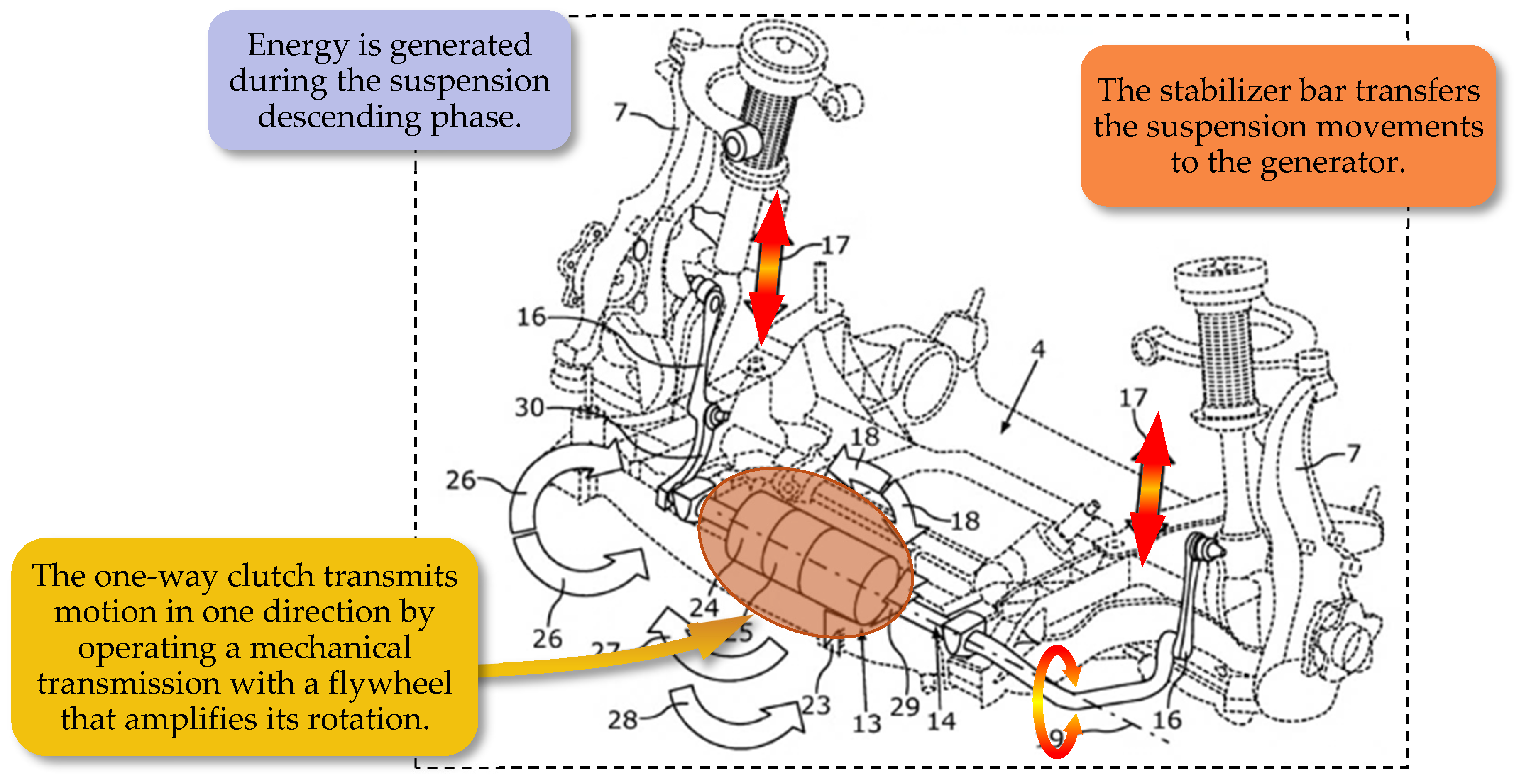
- BMW Patents a System for Recovering Energy Through the Suspension. Available online: https://www.highmotor.com/en/BMW-patents-energy-recovery-system-through-suspension.html (accessed on 15 December 2024).
- New BMW Suspension Turns Speed Bumps into Electricity for Electric Cars. Available online: https://carbuzz.com/news/new-bmw-suspension-turns-speed-bumps-into-electricity-for-electric-cars/ (accessed on 15 December 2024).
- From Exhaust Gases to Energy: Making Combustion Engines More Efficient. Available online: https://cordis.europa.eu/article/id/36176-from-exhaust-gases-to-energy-making-combustion-engines-more-efficient (accessed on 28 December 2024).
- Thermoelectric Energy Harvesting 2013–2023: Devices, Applications. Opportunities. Available online: https://www.idtechex.com/en/research-report/thermoelectric-energy-harvesting-2013-2023-devices-applications-opportunities/354 (accessed on 3 January 2025).
- 2nd Generation Prius Plug-In Hybrid. Available online: https://www.toyota-europe.com/news/2017/2nd-generation-prius-plug-in-hybrid (accessed on 3 January 2025).
- All-New Toyota Prius Plug-in Hybrid. Available online: https://newsroom.toyota.eu/all-new-toyota-prius-plug-in-hybrid-0/ (accessed on 5 January 2025).
- Toyota Shows off Solar Prius with 860 W Output from 34% Efficient Cells. Available online: https://naturalsolar.com.au/solar-news/toyota-shows-off-solar-prius-with-860-w-output-from-34-efficient-cells/ (accessed on 5 January 2025).
- Toyota’s New Electric SUV Has a Solar Roof and a Steering Yoke Like Tesla. Available online: https://www.theverge.com/2021/10/29/22752539/toyota-bz4x-electric-suv-steering-yoke-solar-roof (accessed on 9 January 2025).
- Everything About the Sonata Hybrid’s Solar Roof. Available online: https://www.hyundaimotorgroup.com/story/CONT0000000000091508 (accessed on 10 January 2025).
- Ioniq 5 the All-Electric SUV. Power Your World. Available online: https://laxmihyundai.com/electric/ioniq-5-electric/convenience (accessed on 15 January 2025).
- Solar Car City Car for Daily Urban Mobility. Available online: https://www.squadmobility.com/ (accessed on 15 January 2025).
- Long Range Solar Electric Vehicle—Lightyear 0. Available online: https://lightyear.one/lightyear-0/ (accessed on 16 January 2025).
- Featured Collection—Edison Future. Available online: https://edisonfuture.com/collections/frontpage (accessed on 20 January 2025).
- Edison Future EF1-T: Everything We Know So Far. Available online: https://www.topspeed.com/edisonfuture-ef1-t-everything-we-know/ (accessed on 20 January 2025).
- EV Solar Charger Deposit. Available online: https://gosun.co/products/ev-solar-charger-deposit (accessed on 28 January 2025).
- Mercedes-Benz Testing New Solar Paint. Available online: https://www.pv-magazine.com/2024/12/02/mercedes-benz-testing-new-solar-paint/ (accessed on 28 January 2025).
- Ji, D.; Cai, H.; Ye, Z.; Luo, D.; Wu, G.; Romagnoli, A. Comparison between Thermoelectric Generator and Organic Rankine Cycle for Low to Medium Temperature Heat Source: A Techno-Economic Analysis. Sustain. Energy Technol. Assess. 2023, 55, 102914. [Google Scholar] [CrossRef]


| Reference | Developed System | Harvesting Technology | Application Point | Specific Design Features | Recovered Power |
|---|---|---|---|---|---|
| W. Salam et al. [13] | RSA for EVs | Electric generator | Suspension inside the wheel | Racks, bevel pinions, and freewheel clutch | 380 W |
| M. Abdelrahman et al. [29] | Energy recovery shock absorber for electric buses | Electric generator | Inside the suspension | Slotted link mechanism, bevel pinions, and freewheel clutch | 6.591 W |
| P. Techalimsakul et al. [30] | Suspension-based vibration absorber for 2-ton EVs | Electric generator | Inside the suspension | Racks, bevel pinions, and freewheel clutch | 8.253 W |
| H. Li et al. [31] | RSA | Electric generator | Inside the suspension | Racks, bevel pinions, and freewheel clutch | 4.25 W |
| Z. Wang et al. [32] | RSA for EVs | Electric generator | Inside the suspension | Twin ball screws, cylindrical gear, and freewheel clutch | 3.701 W |
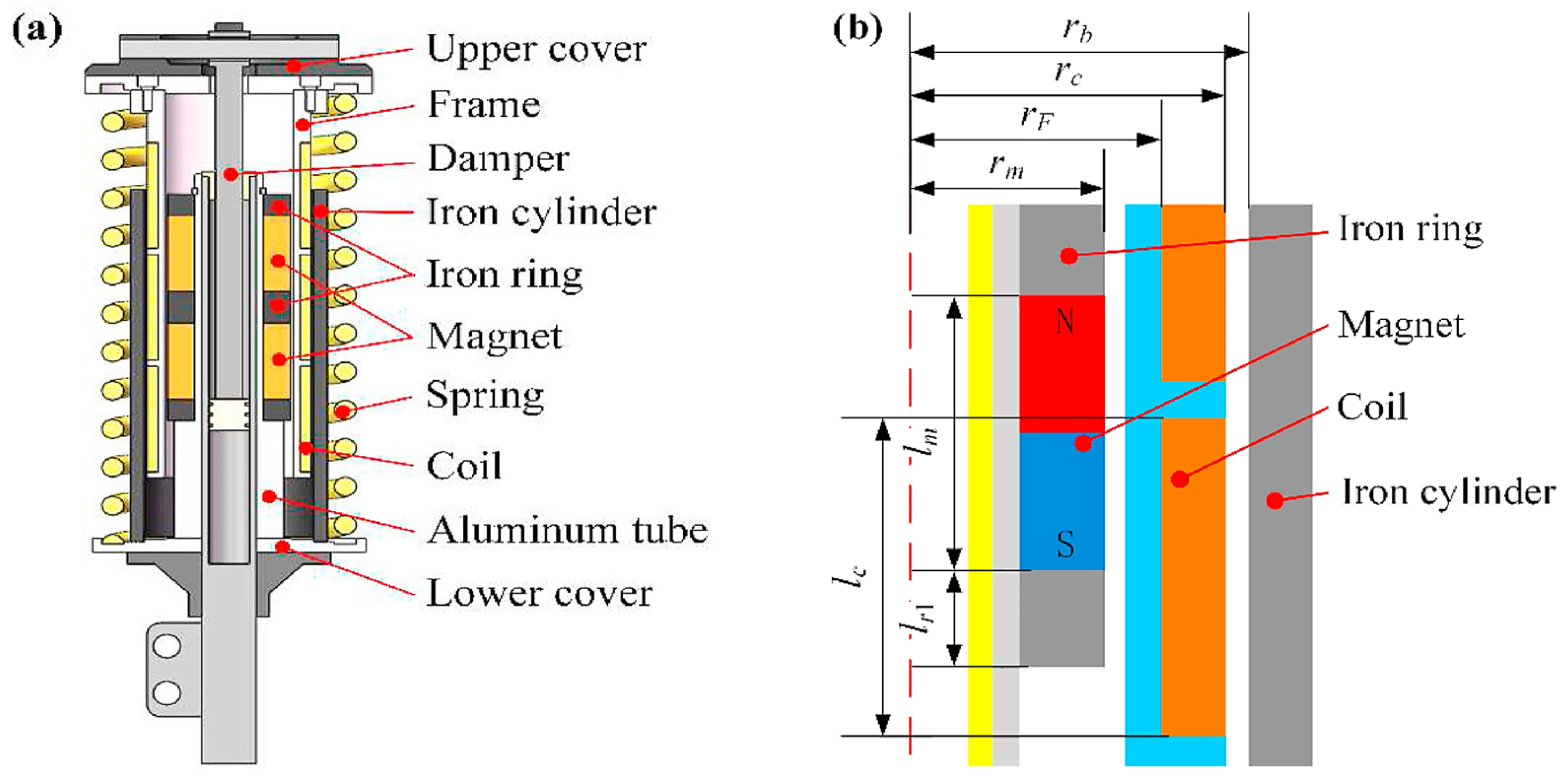
| R. Zhou et al. [14] | Magnetic energy-harvesting suspension | Electromagnetic generator | Harvester device in the suspension spring–damper system | Stator with two magnets and mover with three coils | 0.34 W |
| M.R. Hajidavalloo et al. [33] | Ball screw-based energy-harvesting shock absorber | Electromagnetic generator | Device included in the suspension assembly | Ball screws, planet gear, sun gear, and inert pendulum vibration absorber | ~70 to ~133 W (1) |
| W. Jiang et al. [34] | Dual-mode magnetic suspension | Electromagnetic generator | Device integrated into the suspension spring–damper system | Stator with a permanent magnet ring and mover with three coils | 7.6 V (excitation 2.8 mm and 21 Hz) |
| Y. Hu et al. [35] | Hybrid generator with an S-TENG and EMG | Electromagnetic generator | Device integrated into the suspension spring–damper system | One slider with an S-TENG system (CU foils and PI films) and coils for EMG; one stator with a Halbach magnet array | from 2.791 V to 3.176 V in 30 min (2) |
| J. Zou et al. [38] | Hydraulic interconnected integrated regenerative suspension | Electric generator | Energy harvesting via hydraulic cylinders that replace the dumper | Hydraulic motor generator group, a high- and low-pressure accumulator, 4 actuators, and 4 hydraulic rectifiers. | 87.69 W to 147.86 W |
| W. Zhang et al. [39] | Mechanical–electric–hydraulic regenerative suspension | Electric generator | Device positioned at a point adjacent to the vehicle’s suspension. | Device with a vane damper, hydraulic commutator, and HMG, driven by a rod directly connected to the suspension | 1104 W |
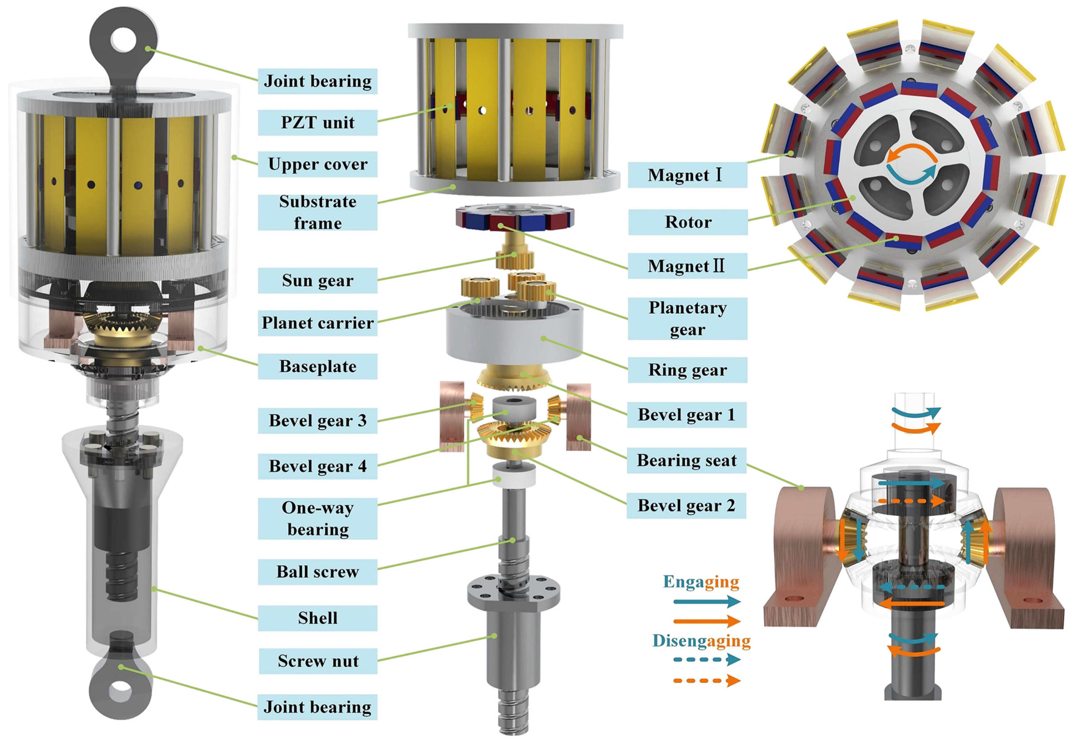
| B. Zhang et al. [15] | Piezoelectric energy-harvesting shock absorber | Direct piezoelectric effect | Device included in the suspension assembly | Ball screw, freewheel, and planetary mechanism for one-way rotation and speed amplifier. Rotor with alternating permanent magnets that interact with those in the piezo module of the stator | Max: 7.51 W, Average: 1.89 W |
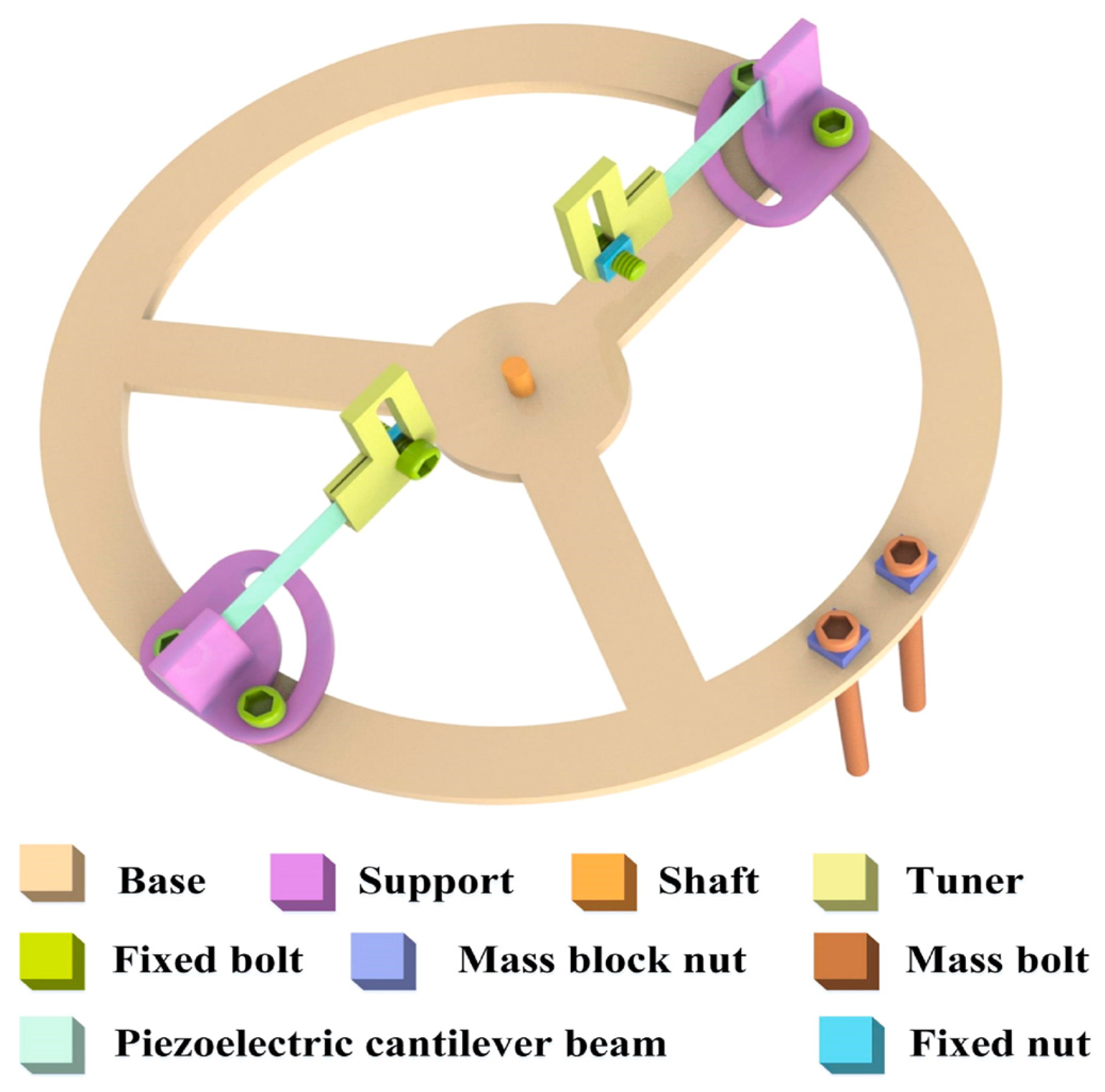
| G. Yu et al. [42] | Rotating piezoelectric energy harvester for automotive motion | Direct piezoelectric effect | Base disc with piezoelectric cantilever beams on the vehicle wheel | Piezoelectric cantilever beams with a tip mass constrained to a circular base connected to the vehicle wheel | 6.25 mW |
| Y. Li et al. [43] | Piezoelectric harvesting from suspension vibrations | Direct piezoelectric effect | Piezoelectric cantilever beams applied to vehicle suspensions | Gear wheel driven by a rack that deforms a vector of piezoelectric elements during rotation | 86.4 mW |
| S. Hazeri et al. [19] | Energy harvesting by tire deformations | Direct piezoelectric effect | Piezoelectric elements on the tire surface | 56 circular piezoelectric elements attached to the central tire’s surface | 2.31 W |
| P.S. Surya Dadi et al. [20] | Energy harvesting by tire deformations | Direct piezoelectric effect | Piezoelectric elements on the tire surface | 75 piezo elements on a 600 mm diameter wheel | 4.346 mW (60 km/h), 7 mW (80 km/h) |
| M. Ikbal et al. [44] | Energy harvesting by tire deformations | Direct piezoelectric effect | Piezoelectric elements inside the tires | PVDF-based piezo-elements integrated into a sandwich made from PTFE and rubber on a TPU and cap | max: 3.42 mW, med: 0.20 mW |
| K.S. Devi et al. [45] | Harvesting by vibration, pressure variations, and deformations of tires | Direct piezoelectric effect | Piezoelectric elements on the suspension system | Piezoelectric patches mounted onto the suspensions to recover energy and to provide information regarding mechanical stress and vibration variations | max: 12 W average: 5 W |
| B.-G. Koo et al. [18] | Piezoelectric harvesting by engine vibrations | Direct piezoelectric effect | Cantilever piezoelectric beam on the engine block | Piezoelectric cantilever beams with the tip load mounted on the top part of the engine | 0.038 mW at 2200 rpm; 0.357 mW at 3200 rpm |
| S. Alhumaid et al. [46] | Rotational piezoelectric harvester | Direct piezoelectric effect | Piezoelectric elements in a cylindrical stator integrated in the suspension | Racks and pinions for motion conversion, freewheel clutches for one-way rotation; the deformation of piezo-elements obtained by magnetic interaction | 14.86 mW |
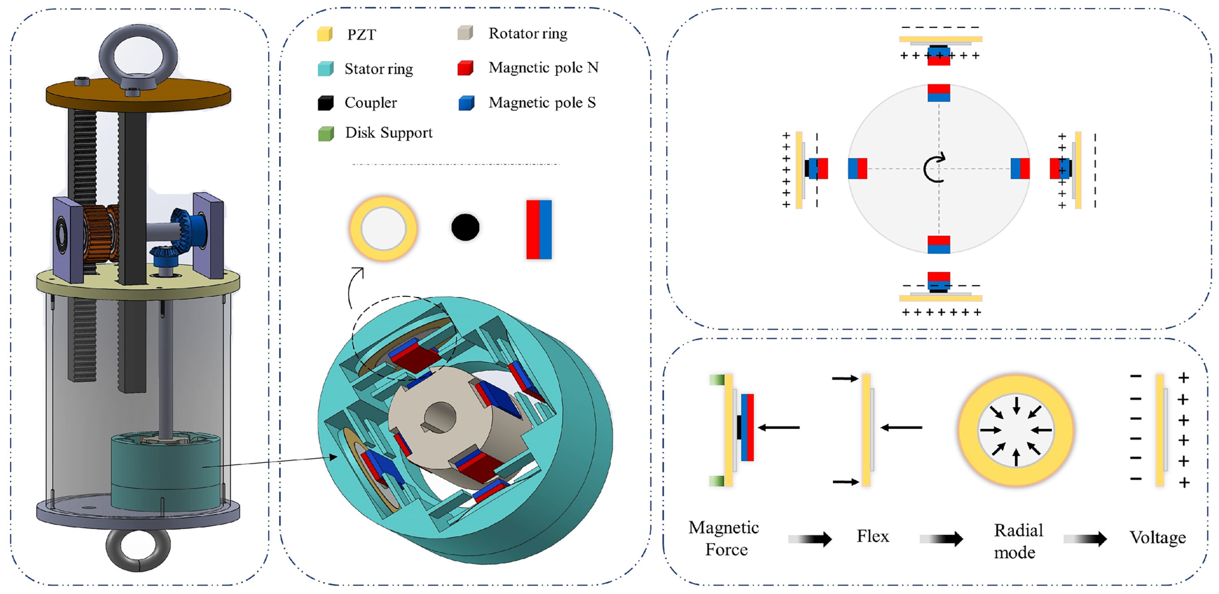
| Z. Zhao et al. [47] | Piezoelectric harvesting by suspension vibrations | Direct piezoelectric effect | Piezoelectric patch in a rotary drum included in the suspension assembly | Ball screw for motion conversion and magnetic interaction for mechanical stress of piezoelectric elements | 24.28 W (60 km/h), 3346 W (30 km/h) (3) |
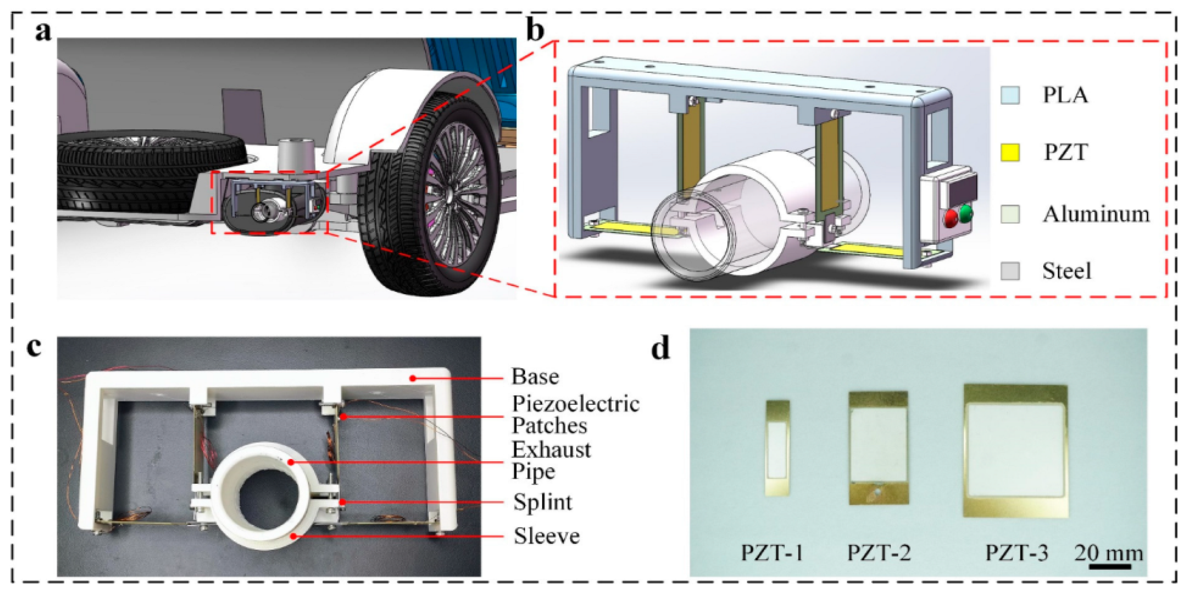
| J. Huang et al. [16] | Vibration energy recycling in the exhaust pipe | Direct piezoelectric effect | Piezoelectric elements around the exhaust pipe | Piezoelectric beams constrained on one side to a fixed frame and on the other to a support attached to the exhaust pipe | 23.4 μW |
| F. Madaro et al. [17] | Piezoelectric harvester to convert the kinetic energy of exhaust gases | Direct piezoelectric effect | Piezoelectric elements inside the exhaust pipe | Piezoelectric converter positioned on an aluminum body in correspondence with the silencer | Max.: 42 μW, Average: 33 nW |
| Song et al. [37] | Electromagnetic energy recovery from vibration | Electromagnetic-pneumatic generator | System applied on vehicle suspension | The EP-RSA’s structure comprises three modules: one for vibration input, one for transmission, and one for the generator | Average: 1.26 W |
| Zhang et al. [40] | Hydraulic–electric regenerative suspension | Electric generator | System applied on vehicle suspension | Inflatable hydraulic–electric regenerative suspension | 124 W (5 m/s), 566 W (20 m/s) |
| Morad et al. [48] | Piezoelectric harvesting by suspension vibrations | Direct piezoelectric effect | System applied on vehicle suspension | 16 piezoelectric units arranged in four layers. Each block of four units uses TPU dampers for vibration absorption, while diode bridges rectify the voltage output into DC | Peak output of 146 V (4) |
| References | Propulsion Category | Harvesting Technology | Conversion Efficiency | Recovered Power | Operating Temp. | Design Features | Advantages | Challenges |
|---|---|---|---|---|---|---|---|---|
| Y. Zhao et al. [87] | Internal Combustion Engine | Thermoelectric Generators (TEGs) | 1.80% | Max output value 236.02 W | 200–650 °C (1) | Direct heat-to-electricity conversion | Exergy loss analysis, optimizing exhaust parameters | Low power output, integration complexity |
| R. Sok et al. [60] | - | 1.1 kW | 250 °C (1) | EG integration for diesel engines, boosting BTE by 1.1% | ||||
| G. Sharma et al. [65] | 3.5% | 37 W | - | TEGs on diesel engine exhaust, max output 37 W | ||||
| R. Sok et al. [22] | - | 3 W | 200–300 °C (1) | TEG–heat exchanger modeling, accurate power prediction | ||||
| Md. Asaduzzaman et al. [68] | 4.65% steel TEG, 4.63% copper TEG | 2.0 W steel TEG, 2.9 W copper TEG | 297–300 °C (1) | Copper vs. steel TEGs, copper has 48% higher power | ||||
| D. Luo et al. [74] | 1.53% | 38.07 W | 363.15 K (1) | Numerical model for TEG placement impact | ||||
| Quan et al. [77] | 0.97% | 118.24 W | 623 K | Structure optimization of AETEGs | ||||
| Quant et al. [78] | 5 TEG units reach 1.06% at 125 km/h | 721.76 W | 663 K | Solution for AETEG system optimization and assessment of fuel efficiency | ||||
| J. Rijpkema et al. [59] | Organic Rankine Cycle (ORC) | 1.6% (water) (2); 2.5% (ethanol) (2); 3.4% (cyclopentane) (2) | 0.5–5.7 kW 1.8–9.6 kW 1.0–7.8 kW | 260–320 °C (1) | High energy recovery, suitable for trucks | ORC for heavy-duty diesel engines, 3.4% recovery with cyclopentane | Requires additional components, space constraints | |
| D. Di Battista et al. [62] | 10% | 3 kW (I stage), 3.5 kW (ORC stage) | 300–400 °C (1) | ORC + turbo-compounding, up to 10% brake power recovery | ||||
| N. Roeinfard et al. [66] | 25–40% (HTKC), 8–13% (ORC) | 10–25 kW (HTKC), 2–7 kW (ORC) | 700–900 K (3) | ORC vs. Kalina cycle, HTKC achieves 25–40% efficiency | ||||
| S. Lee et al. [81] | Electric Vehicles | Heat Pump Optimization | Up to 13% (energy saved in EV) | - | - | Optimal WHRS (waste heat recovery strategy) | Multi-level heat recovery strategy reduces power consumption by 13% | Dependent on driving conditions |
| Md.Z.U. Saif et al. [84] | Braking Systems | Thermoelectric Generators (TEGs) in Braking | 0.3–4% | 41.98 W | 326 °C | Heat recovery during braking for battery charging | TEG model using brake heat for HEVs, CFD analysis | Limited power output, efficiency depends on braking conditions |
| A. Coulibaly, et al. [85] | 0.3% | 4.25 W (4) 3.25 W (5) | 25–200 °C (6), 25–175 °C (6) | Brake disc TEGs, recovery up to 4 W | ||||
| Md.Z.U. Saif et al. [86] | - | 71.136 A 97.001 A | 250 °C (7) 326 °C (7) | Impact of temperature on TEG efficiency for regenerative braking |
| Reference | Developed System | Harvesting Technology | Application Point | Specific Design Features | Performance |
|---|---|---|---|---|---|
| J.W. Park et al. [88] | Energy recovery for powering sensors and electronic accessories | Electric generator | Thermoelectric generator attached to the exhaust pipe and the wind fan on the front bumper | Electronic devices: parking assistant (RearSense) powered by a thermo-electric unit, pedestrian display powered by wind fan | RearSense: 3900 μWh for 20 °C heat difference; PedDisplay: 1700 μWh for 15 mph wind speed |
| S.-B. Kim et al. [89] | Hybrid generator with a TEG and piezoelectric system | Electric generator | Right-side engine head | Piezoelectric cantilever beam mounted on a TEG for amplifying power generation | 7.619 mW and 0.5 g vibrational source; increment > 50% compared to no vibration |
| D. Yadav et al. [90] | Energy recovery from TEGs, regenerative braking, and piezoelectric solution | Electric generator | TEG on turbocharger exit and exhaust pipe; regenerative braking on braking system; piezoelectric on suspensions | Integration of multiple energy recovery methods | TEG: 1068 W, piezoelectric system: 332 W; breaking system: increment of generated current: 157% (low braking intensity), 238.72% (high intensity) |
| Park et al. [91] | Energy recovery from solar PV panels | Electric generator | Four sides of the vehicle: roof, rear window, left door, and right door | PV photovoltaic power generation modules attached on the car and tested with various inclinations and azimuths | 0.0158 kWh for a single drive (approximately 10 min) and 221 kWh for one year (considering six hours a day) |
| Z. Jin et al. [92] | Energy recovery from solar PV panels | Electric generator | Car roof | Foldable scissors mechanism for efficient energy conversion (PVPGM, photovoltaic power generation module) | Max output power: 1.736 W, max. electricity transfer efficiency: 57.7% |
| M.A. Shamseldin [94] | Energy recovery from wind fan | Electric generator | Car front bumper | Combination of model reference adaptive control (MRAC) with different types of PID for catching the wind in the opposite direction of a moving vehicle | Recovery of 59.26% of the total wind power under ideal conditions |
| Z.A. Khan et al. [95] | Energy recovery from wind fan | Electric generator | Car front bumper | Wind fan integration for power recovery, reducing dependence on charging | Power: 100 W at a speed of 90 mph |
| Z. Zhao et al. [96] | Energy recovery from wind turbine | Electric generator | Vehicle’s front grille | Savonius vertical-axis wind turbine (SVAWT) | Blades’ absorbing power: 3.9 W ÷ 7.1 W (varies with wind speed) |
| C.K. Mytafides et al. [93] | Hybrid TEG- and DEEC-based energy harvester | Electric generator | Possible application on the external surface of the vehicle body | TEG and DSSCs within CFRP composites | Power density of 6.4 mW/cm2 |
| Car Manufacturer | Model | Year | Extended Autonomy |
|---|---|---|---|
| Toyota (Toyota, Japan) | Prius Plug-in Hybrid | 2017 | 5 km/day (~1800 km/year) |
| Prius PHEV | 2023 | 9 km/day (~3200 km/year) | |
| BZ4X | 2022 | 1800 km/year | |
| Hyundai (Seoul, Republic of Korea) | Sonata Hybrid | 2019 | ~1460 km/year |
| Ioniq 5 | 2022 | 1200–1500 km/year | |
| Squad Mobility BV (Breda, The Netherland) | Squad Solar City Car | 2023 | 22–31 km/day |
| Lightyear (Venray, The Netherland) | Lightyear 0 | 2022 | 70 km/day |
| Edison Future | EF1-T Pickup Truck | 2025 | 24–40 km/day |
| (Anaheim, CA, USA) | EF1-V Delivery Van | 2025 | N.A. |
| Key Parameters | Mechanical Harvesting | Thermal Harvesting | Environmental (Solar/Wind) Harvesting |
|---|---|---|---|
| Operating principle | Recovery of kinetic energy dissipated by the vehicle. | Recovery of waste heat produced by the vehicle. | Production of electrical energy from sunlight and the air flow produced by the moving vehicle. |
| Energetic efficiency | Mechanical harvesting architectures have the highest efficiency among harvesting technologies, recovering between 50–70% of the energy dissipated by the vehicle. | TEGs’ efficiency ranges from 5–10% and is limited by the materials, the physics of the conversion process, and operating conditions. Instead, ORC systems reach an efficiency range of 10–25% depending on the circuit’s thermodynamic losses, the working fluid, and the system design. | Commercial PV panels have a conversion efficiency that varies from 15 to 22%, even reaching 34% with the latest generation, and depends on the solar incidence and the environmental conditions. Wind harvesting reaches 30–45% efficiency but depends greatly on size, airflow, and installation location. |
| Costs | Low installation cost. High maintenance costs. | High installation cost. Low maintenance costs. | Low installation and maintenance costs for solar harvesting. High installation cost and low maintenance costs for wind harvesting. |
Disclaimer/Publisher’s Note: The statements, opinions and data contained in all publications are solely those of the individual author(s) and contributor(s) and not of MDPI and/or the editor(s). MDPI and/or the editor(s) disclaim responsibility for any injury to people or property resulting from any ideas, methods, instructions or products referred to in the content. |
© 2025 by the authors. Licensee MDPI, Basel, Switzerland. This article is an open access article distributed under the terms and conditions of the Creative Commons Attribution (CC BY) license (https://creativecommons.org/licenses/by/4.0/).
Share and Cite
Rausa, G.; Calabrese, M.; Velazquez, R.; Del-Valle-Soto, C.; Fazio, R.D.; Visconti, P. Mechanical, Thermal, and Environmental Energy Harvesting Solutions in Fully Electric and Hybrid Vehicles: Innovative Approaches and Commercial Systems. Energies 2025, 18, 1970. https://doi.org/10.3390/en18081970
Rausa G, Calabrese M, Velazquez R, Del-Valle-Soto C, Fazio RD, Visconti P. Mechanical, Thermal, and Environmental Energy Harvesting Solutions in Fully Electric and Hybrid Vehicles: Innovative Approaches and Commercial Systems. Energies. 2025; 18(8):1970. https://doi.org/10.3390/en18081970
Chicago/Turabian StyleRausa, Giuseppe, Maurizio Calabrese, Ramiro Velazquez, Carolina Del-Valle-Soto, Roberto De Fazio, and Paolo Visconti. 2025. "Mechanical, Thermal, and Environmental Energy Harvesting Solutions in Fully Electric and Hybrid Vehicles: Innovative Approaches and Commercial Systems" Energies 18, no. 8: 1970. https://doi.org/10.3390/en18081970
APA StyleRausa, G., Calabrese, M., Velazquez, R., Del-Valle-Soto, C., Fazio, R. D., & Visconti, P. (2025). Mechanical, Thermal, and Environmental Energy Harvesting Solutions in Fully Electric and Hybrid Vehicles: Innovative Approaches and Commercial Systems. Energies, 18(8), 1970. https://doi.org/10.3390/en18081970