Article

Study on Flow and Heat Transfer Characteristics of Battery Thermal Management System with Supercritical CO2 for Energy Storage Stations

1
Municipal Sub-Bureau, Sinohydro Engineering Bureau 4 Co., Ltd., Xining 810009, China
2
College of Energy and Power Engineering, Lanzhou University of Technology, Lanzhou 730050, China
*
Author to whom correspondence should be addressed.
Energies 2025, 18(8), 2030; https://doi.org/10.3390/en18082030
Submission received: 16 March 2025 / Revised: 7 April 2025 / Accepted: 11 April 2025 / Published: 16 April 2025
(This article belongs to the Section J1: Heat and Mass Transfer)

Abstract

:
Energy storage stations (ESSs) need to be charged and discharged frequently, causing the battery thermal management system (BTMS) to face a great challenge as batteries generate a large amount of heat with a high discharge rate. Supercritical carbon dioxide (SCO2) is considered a promising coolant because of its favorable properties, including non-flammability, high dielectric strength and low cost for the BTMS. The heat of a battery can be absorbed to a great extent if there is a small temperature rise because as the fluid temperature approaches a pseudo-critical temperature, the specific heat capacity of SCO2 reaches its peak. In this study, a periodic model of the unit BTMS is established, and a numerical simulation is implemented to investigate the effects of different boundary conditions on the heat dissipation of a battery pack. The flow and heat transfer characteristics of SCO2 in the liquid cold plate (LCP) of a battery pack with an extreme discharge rate are revealed. The results show that SCO2 is more preferably used as a coolant compared to water in the same conditions. The maximum temperature and the temperature difference in the battery pack are reduced by 19.22% and 79.9%, and the pressure drop of the LCP is reduced by 40.9%. In addition, the heat transfer characteristic of the LCP is significantly improved upon increasing the mass flow rate. As the operational pressure decreases, the pressure drops of SCO2 decrease in the LCP. Overall, the maximum temperature and the temperature difference in the battery pack and the pressure drops of the LCP can be effectively controlled by using a coolant made out of SCO2. This study can provide a reference for the design of BTMSs in the future.

1. Introduction

The adverse impacts of large-scale production and consumption in the conventional energy industry are further exacerbated by the global energy crisis, while environmental pollution continues to worsen [1]. As a renewable and clean energy source, electricity plays a pivotal role in mitigating energy shortages and advancing decarbonization goals [2]. In this context, ESSs are emerging as a critical strategy for the efficient development and utilization of renewable energy [3].
Lithium-ion batteries exhibit several advantageous properties, including high energy efficiency, superior power density, rapid charging capability, and an extended cycle life [4]. These characteristics make them well suited for ESSs, where they can address critical challenges such as high-power output and frequent charge–discharge cycles [5]. However, operating temperature is a critical factor influencing the safety and reliability of ESSs [6]. Under high-voltage demands to meet ESS operational requirements, battery packs generate significant heat [7]. Prolonged exposure to elevated temperatures degrades performance, shortens service life, and accelerates capacity fade [8]. If this accumulated heat is not effectively dissipated, it can lead to severe consequences, including internal short circuits, thermal runaway, and even catastrophic failure events such as fires or explosions [9]. To mitigate these risks, advanced BTMSs are essential for maintaining safe and stable operation, particularly in high-rate discharge scenarios. Current BTMS research primarily focuses on four cooling methodologies: air cooling, liquid cooling, phase-change materials (PCM), and heat pipes [10]. While air cooling—a passive strategy—offers simplicity, cost-effectiveness, and reliability [11], its inherently low heat transfer coefficient limits its applicability in high thermal load ESS applications [12].
The BTMS utilizing PCM can regulate battery pack temperature rise and maintain thermal uniformity by exploiting latent heat absorption during phase transition [13]. However, this approach fails to adequately address the challenge of rapid temperature escalation during high-rate discharge conditions [14], primarily due to PCM’s inherent limitations of low thermal conductivity and slow heat storage recovery. While heat pipes demonstrate excellent thermal conductivity characteristics [15], their standalone application in BTMSs is impractical, necessitating their integration with supplementary cooling strategies for effective thermal management [16]. These constraints render both PCM and heat pipe solutions suboptimal for ESS battery thermal management applications. Therefore, these cooling methods are not suitable for use in the BTMS of an ESS. Cooling by liquid is the main method used in BTMSs according to recent research [17].
Liquid cooling systems can be categorized into two primary types: direct contact and indirect contact cooling [18]. In direct contact cooling, a battery pack is fully immersed in dielectric coolant for efficient thermal management. While this method provides excellent heat transfer, its long-term operation presents significant challenges with coolant leakage [18], making it impractical for most real-world engineering applications. Alternatively, indirect contact cooling utilizes an LCP to transfer heat from the battery pack to the coolant without direct contact [19].
As a conventional coolant, water is widely used in the thermal management system of electronic equipment [20]. However, single-phase water cooling has become inadequate for handling the progressively higher heat fluxes encountered in modern ESSs. This thermal limitation underscores the need for advanced coolants in BTMSs to achieve more efficient heat dissipation. An experiment was carried out by Hall [21], and its outcome is that the heat transfer coefficient of supercritical fluids is high near the pseudo-critical point. The outstanding characteristics of supercritical carbon dioxide include its low viscosity, significant specific heat and high thermal conductivity [22]. It is applied in a nuclear reactor system as a coolant by Huang et al. [23]. Recent studies have demonstrated the effective use of SCO2 in printed circuit heat exchangers for the thermal management of electronic devices [24], highlighting its strong potential for advanced cooling applications. Khalesi and Sarunac [25] investigated the flow and heat transfer characteristics by using SCO2 as the coolant. They found that there is a high heat transfer coefficient near the pseudo-critical point, but it decreases when it is far away from it. A numerical simulation was used to study the heat transfer of SCO2 in a microchannel by Rosa et al. [26]. The conclusions indicated that the desired cooling effect was provided by controlling the operational pressure according to the heat load of the electronic circuit. Huang et al. [27] studied numerically the thermal characteristics of SCO2 in a wave microchannel. The results indicated that the temperature uniformity of the system was improved by the optimization, but the heat transfer was slightly reduced. A proposed combination of a microchannel of a complex structure and SCO2 was studied by Huang. The effect of hot spots was effectively reduced, and the overall heat transfer was improved. Khan et al. [28] studied the cooling effect of SCO2 for batteries. They found that SCO2 exhibited excellent temperature suppression and temperature differences compared to conventional coolants. But the heat transfer characteristics of SCO2 were not summarized. Yang et al. [29] analyzed the effect of SCO2 at different working pressures in an LCP with a micron channel for a battery. The results showed that the cooling effect of the battery was improved when the pressure was reduced from 8.0 MPa to 7.5 MPa. To sum up, there are broad prospects for SCO2 in improving heat transfer. However, current research on supercritical carbon dioxide primarily focuses on fundamental studies in microchannels, and its application as a coolant is mainly limited to small-scale electronic devices. There is relatively scarce research on the use of SCO2 as a coolant in large-scale battery packs, and the flow and heat transfer characteristics of SCO2 in an LCP have not yet been thoroughly summarized.
Therefore, the aims of the present work are to investigate the flow and heat transfer characteristics of SCO2 in an LCP during the operation of a battery pack with a high discharge rate to improve the heat transfer and pressure drop of a BTMS and to maintain the battery pack’s operation at a safe temperature. A periodic BTMS model with a coolant composed of SCO2 is established and compared to water. The effects of different boundary conditions on the cooling effect of the battery pack and heat transfer characteristic of the LCP are studied by numerical simulation. This study can provide a reference for the design of large-scale BTMSs in the future.

2. Geometry and Numerical Methods

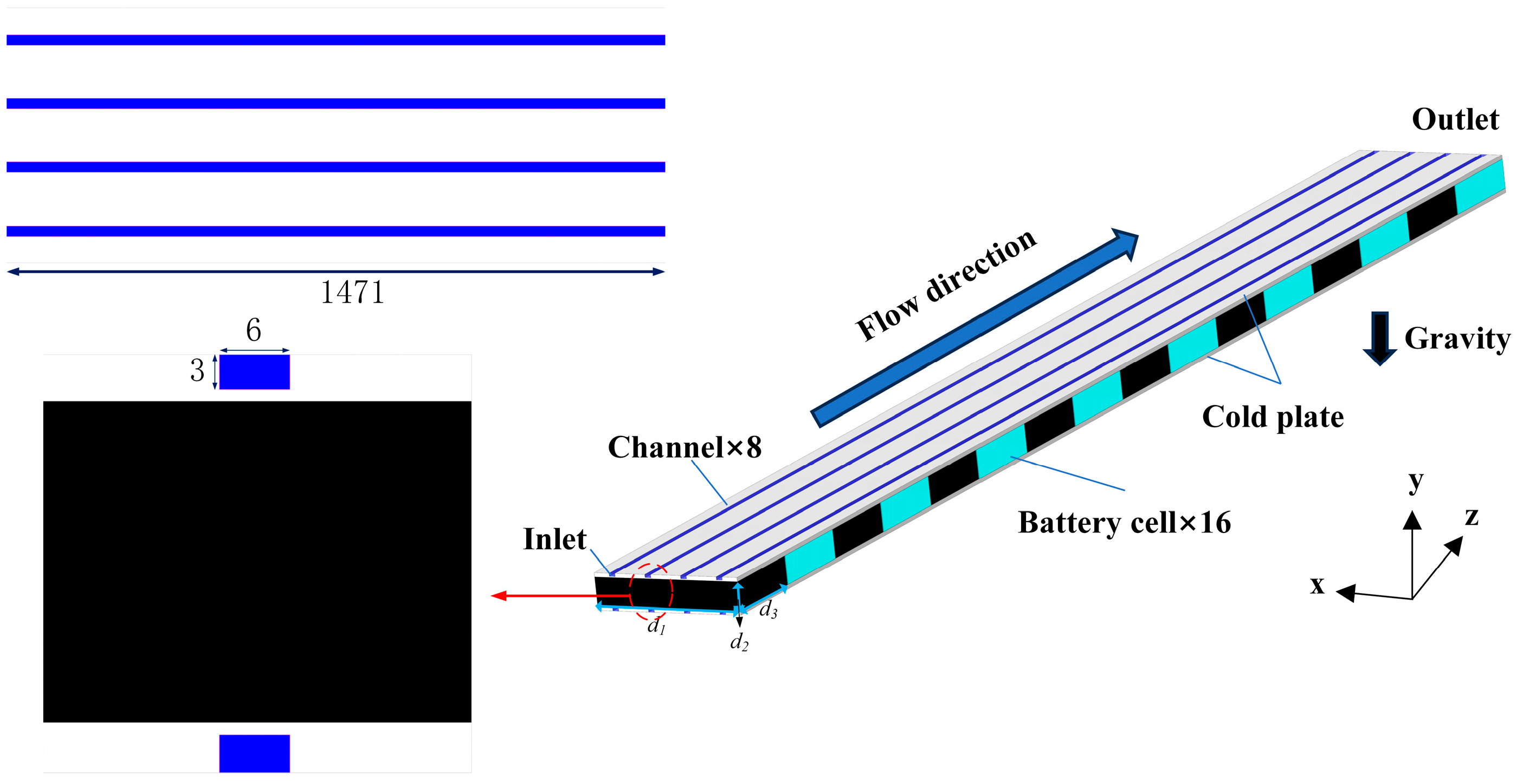
2.1. Geometrical Model

In this study, a geometric model of a BTMS is designed using Creo 9.0. As shown in Figure 1, the model simplifies the battery pack by excluding electrodes and other auxiliary mechanical components. The single-battery model has dimensions of 148 mm (length, d1), 27.5 mm (thickness, d2), and 91 mm (width, d3). Sixteen such batteries are arranged in a series between LCPs, with the assumption of perfect thermal contact between the batteries and LCPs in the numerical simulation. A 1 mm gap is maintained between adjacent batteries to prevent thermal conduction and mitigate the risk of thermal runaway. The LCPs are constructed from structural steel [29], capable of withstanding pressures up to 20 MPa. Each LCP incorporates four identical cooling channels, each with a cross-sectional area of 6 × 6 mm2. Due to the symmetry of the battery and cooling system, only half of the LCPs on either side of the battery pack are modeled. The upper and lower walls of the LCPs are treated as interior periodic boundaries, while the side walls are also defined with periodic boundary conditions. Detailed parameters of the BTMS are provided in Table 1.

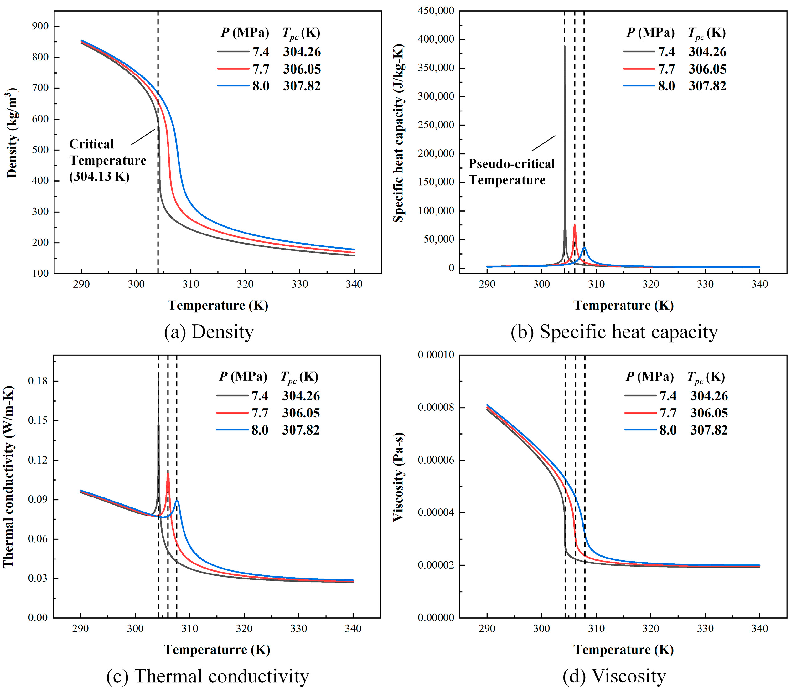
2.2. Governing Equations

The heat generated by the battery is considered to be uniform, and it is calculated according to the Bernadi model [30]:
Q = 1 V s I U O C V U + I T s U O C V T
where Q is the heat generated by the battery, Vs is the volume of a single battery, UOCV is the open circuit voltage of the battery, U is the working open circuit voltage of the battery, Ts is the temperature of the battery, and I is the current of the battery. The heat generated by the battery is composed of the electrochemical reaction heat inside the cell and the internal resistance joule heat of each part [31]:
Q = 1 V s I 2 R + I T s U O C V T
where R is the internal resistance of the battery. The material of the battery is assumed to be uniform, and the density, specific heat and thermal conductivity do not change with temperature. Heat conduction is considered, while heat convection and heat radiation are ignored in the numerical simulation. The energy conservation equation of the battery [32] is expressed as
ρ s c p s T t = x λ x T x + y λ y T y + z λ z T z + Q
where ρs is the density of the battery, cps is the specific heat capacity, and λx, λy, and λz are the thermal conduction coefficients along the coordinates in the battery. The material of LCP is considered to be isotropic, the fluid is incompressible, and the steady flow is without a heat source. The governing equations of mass conservation, the momentum conservation, and the energy conservation are expressed [33] as follows:
ρ c u = 0
ρ c ( u u ) = p + μ 2 u
ρ c c p c ( u T c ) = λ c 2 T c
λ l 2 T l = 0
where ρ, u, p, cp, λ, and μ are the density, velocity, pressure, specific heat, thermal conductivity, and dynamic viscosity, respectively, and ∇ is the gradient operator. The subscripts c and l represent the coolant and LCP, respectively. The SST k-ω turbulence model is applied to calculate due to its great robustness, and the flow characteristics of the fluid in the near-wall region can be extensively described. The transport equations [34] are expressed as follows:
t ( ρ c k ) + x i ( ρ c k u i ) = x j ( Γ k k x j ) + G k Y k + S k
t ( ρ c ω ) + x i ( ρ c ω u i ) = x j ( Γ ω ω x j ) + G ω Y ω + S ω + D ω
where Γk and Γω represent the effective diffusivity of turbulent kinetic energy k and specific turbulent dissipation rate ω, respectively, Gk represents the turbulence kinetic energy generated by the mean velocity, Gω represents the generation of ω, Yk and Yω are the dissipation of k and ω, respectively, Sk and Sω are the source terms of k and ω, respectively, and Dω represents the cross-diffusion term [35].

2.3. Parameter Definition

There is a dimensionless number Re that describes the characteristics of the fluid flow state, and its equation is expressed as follows:
R e x = ρ c u d c μ
where dc represents the hydraulic diameter of the channel, and μ is the molecular viscosity. The dimensionless number Nu is usually used to describe the heat transfer characteristics of an LCP, and its equation is expressed as follows:
N u x = h x d c λ
where λ is the thermal conductivity of the coolant along the mainstream. hx is the heat transfer coefficient, and its equation is expressed as
h x = q w ( T w , x T b , x )
where qw is the heat flux, Tw,x is the wall temperature, and Tb,x is the bulk temperature of the coolant.

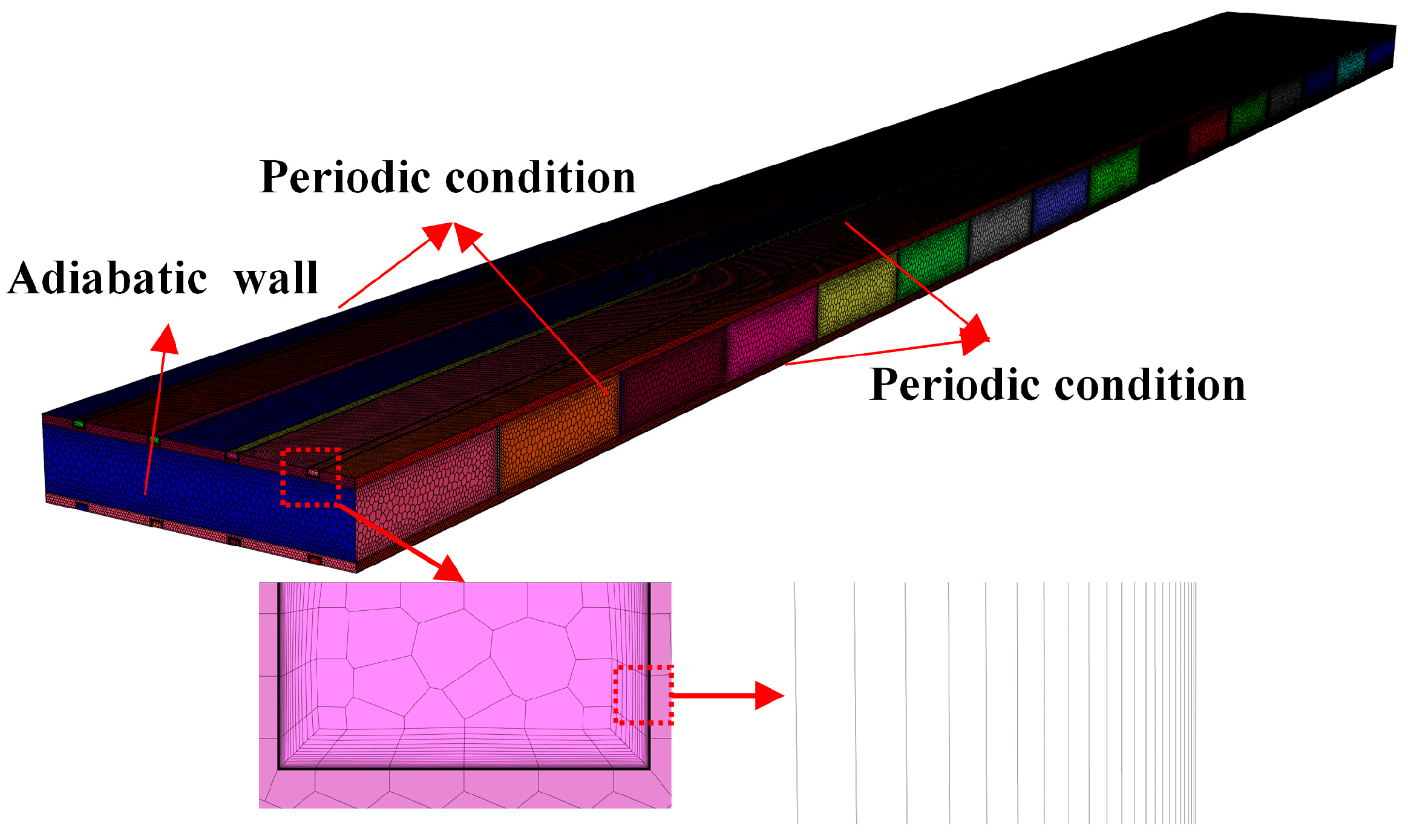
2.4. Boundary Conditions

Ansys Fluent (2021R1) is used in the numerical simulation. The mass flow is considered as the inlet boundary condition, and the initial temperature of the inlet is set to 300 K. The cooling system adopts a mass flow rate of 0.002~0.006 kg/s. The pressure outlet boundary condition is used at the outlet. The thermophysical properties of SCO2 are obtained from the NIST Refprop 9.1 and entered into Fluent for the calculation. The variations in the thermophysical properties of SCO2 with pressure and temperature are shown in Figure 2. As described, SCO2 reaches critical point at 7.38 MPa and 304.13 K. The operating conditions in this study cover pressures of 7.4–8.0 MPa with discharge rates of 3C–5C in this study. The pseudo-critical temperatures of SCO2 are 304.26 K at 7.4 MPa, 306.05 K at 7.7 MPa, and 307.82 K at 8.0 MPa. The listing of the computational cases is shown in Table 2. When the bulk temperature exceeds the pseudo-critical temperature, SCO2 exhibits sharp decreases in density, thermal conductivity, and viscosity while demonstrating a pronounced specific heat capacity peak near the pseudo-critical point. For the flow characteristics, SCO2 in the LCP maintains vigorous turbulent flow, while water remains laminar under identical conditions. Accordingly, the SST k-ω turbulence model was employed for SCO2 simulations, with a laminar model applied for water. The governing equations were discretized using a second-order upwind scheme, with pressure–velocity coupling resolved via the SIMPLEC algorithm. Gravity was applied vertically downward along the flow direction, and all solution residuals were converged below 10−8 for all variables.

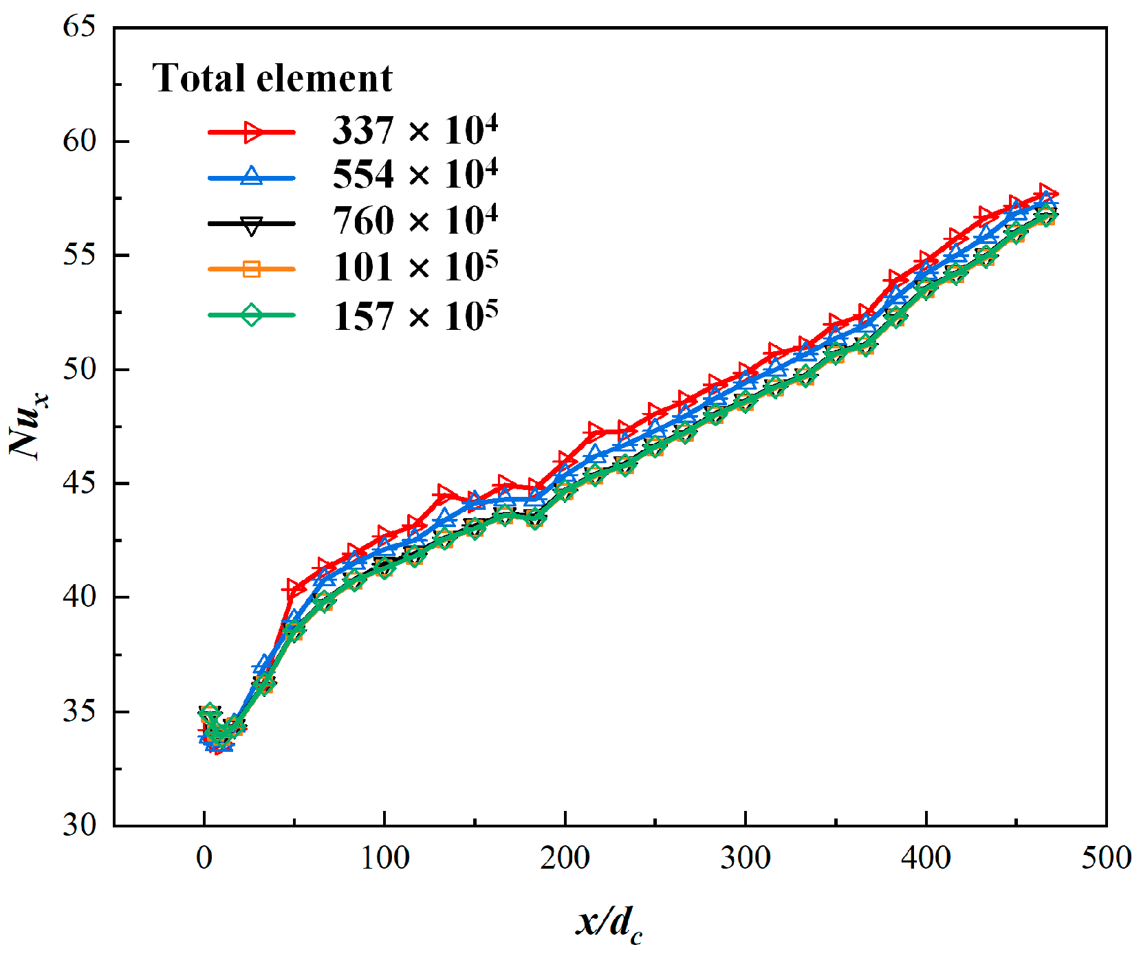
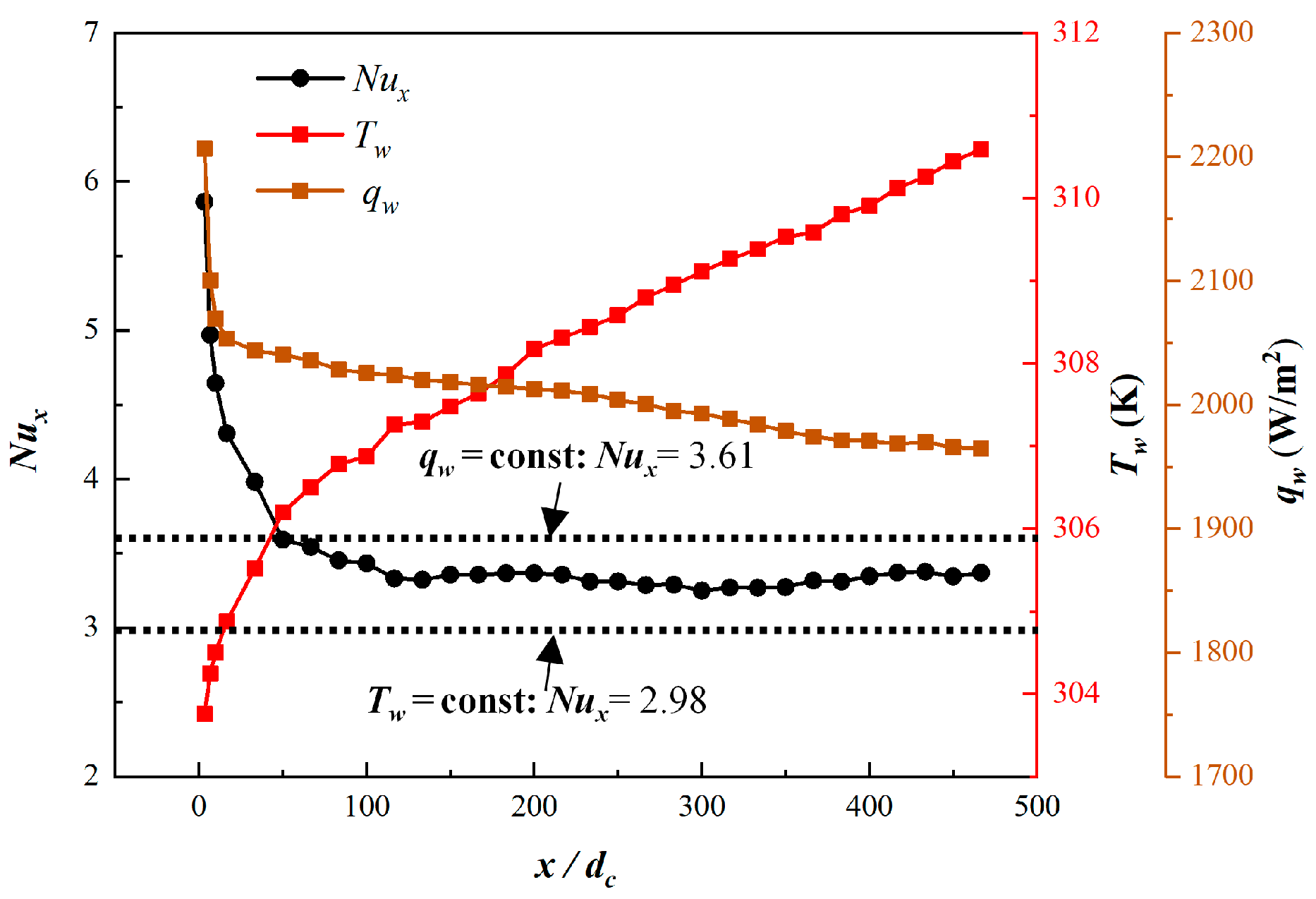
2.5. Grid Independence Tests and Validation

The grid independence test is conducted to verify the numerical accuracy of the simulations. Figure 3 presents the periodic computational domain meshed with a Poly-Hexcore grid scheme. The boundary layer was particularly refined, with the first grid layer height set to 0.001 mm from the wall to maintain a non-dimensional wall distance (y+) below 1. Figure 4 shows the variation in the local Nusselt number with different grid resolutions. While noticeable differences exist between 3.37 × 10⁶ and 7.60 × 10⁶ grid elements, further refinement to 1.57 × 10⁷ elements yields a maximum Nusselt number variation of only 0.37%, indicating grid independence. Since additional grid refinement beyond 7.60 × 10⁶ elements showed no significant improvement in accuracy while substantially increasing computational costs, this optimal grid resolution is selected for all subsequent simulations.
A supercritical BTMS has not yet been established, and the verification of a simulation using water as the coolant is discussed. According to fundamental heat transfer principles, the Nusselt number for fully developed laminar flow remains constant, with theoretical values of 3.61 for constant heat flux conditions and 2.98 for constant wall temperature conditions in square channels. A single battery is set as the energy source in the numerical simulation, and there is a gap between the batteries in this work, resulting in the periodic disruption and re-establishment of the thermal boundary layer within the LCP. This configuration induces axial non-uniformity in the wall heat flux distribution, accompanied by a progressive streamwise temperature increase along the LCP walls, as illustrated in Figure 5. The Nusselt number of the developed region in the LCP is between the constant heat flux condition and the constant wall temperature condition, reflecting the hybrid thermal characteristics of this non-ideal system.

3. Results and Discussion

The temperature of the battery pack rises rapidly with a high discharge rate. The working environment of the battery pack gradually becomes harsh when the heat is not dissipated effectively. The main design purpose is that the maximum temperature and the temperature difference are controlled effectively for the BTMS. It is generally considered that the maximum temperature of the battery should not exceed 328 K, and the temperature difference between the highest-maximum-temperature cell and the lowest-maximum-temperature cell should not exceed 5 K [36]. The implementation of SCO2 as a coolant offers significant advantages in BTMS applications. When operating near its pseudo-critical temperature, SCO2 exhibits a specific heat capacity peak, enabling substantial heat absorption with a minimal temperature increase. In addition, the up flow in the LCP for the battery pack is in the lower half of the channel, and the down flow in the LCP for the battery pack is in the upper half of the channel on account of the periodic model.

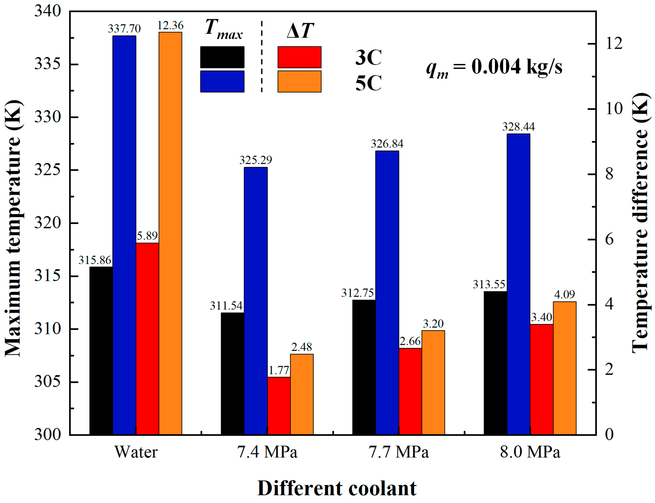
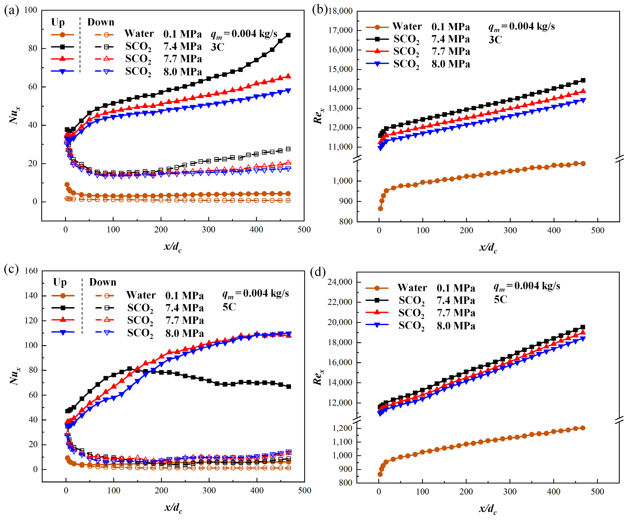
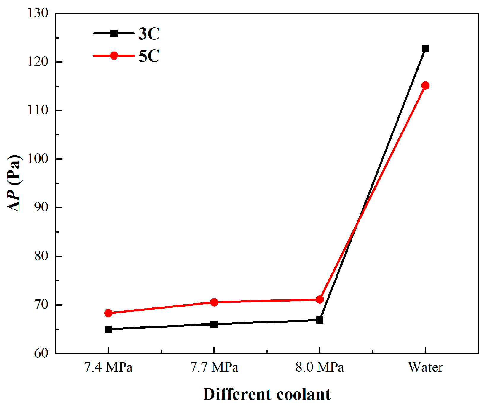
3.1. Comparison of SCO2 with Water

In this section, the effects of SCO2 and water on the heat dissipation of the battery pack are compared. Figure 6 presents the results of the maximum temperature and the temperature difference in the battery pack with the rate of discharge at 3C and 5C and the mass flow rate of 0.004 kg/s. SCO2 outperforms water in reducing the temperature of the battery pack. The maximum temperature and the temperature difference in the battery pack are 315.8 K and 5.89 K, respectively, regarding the battery pack at 3C with the coolant of water. The maximum temperature and the temperature difference in the battery pack are 311.54 K and 1.77 K, respectively, with the coolant of SCO2 at 7.4 MPa. The maximum temperature and the temperature difference in the battery pack are 313.55 K and 3.4 K, respectively, when the operational pressure increases from 7.4 MPa to 8.0 MPa. It is discovered that the maximum temperature and the temperature difference are reduced, respectively, by 10% and 69.9% compared to water. Moreover, the differences in heat dissipation effects between SCO2 and water are further increased at 5C. Compared to water, the maximum temperature and the temperature difference decreased by 19.22% and 79.9%, respectively, when using the coolant of SCO2. The temperature distributions of the battery pack that has five periodic units along the x and y coordinates are extracted with different coolants, as shown in Figure 7. It is obvious from the results that the temperature distributions of the battery pack using SCO2 as a coolant is more uniform than those using water. Compared to water, the temperature uniformity of SCO2 is more obvious when the battery pack is discharged at 5C. At the same time, the lower the operational pressure in the LCP, the better the temperature uniformity of the battery pack.
Figure 8 illustrates the effects of heat transfer and flow characteristics in the LCP at different discharge rates and pressures. Figure 8a shows the variation in the local Nusselt number along the mainstream for the battery at a discharge rate of 3C. The results indicate that the Nusselt number for SCO2 is significantly higher than that of water. This difference could be primarily attributed to the highly turbulent flow of SCO2 in the LCP, whereas water remains in a laminar flow regime. As shown in Figure 8b, the Reynolds number of SCO2 in the LCP exhibits a sharp increase along the mainstream, whereas water displays a much more gradual rise. Notably, the local Reynolds number increases as the operating pressure drops from 8.0 MPa to 7.4 MPa, leading to a corresponding enhancement in the local Nusselt number. When the battery pack’s discharge rate increases to 5C, both the local Nusselt number and Reynolds number exhibit enhanced growth rates along the mainstream due to the elevated heat flux, as shown in Figure 8c,d. However, at an operating pressure of 7.4 MPa, the local Nusselt number begins to decline beyond x/d = 100, indicating the gradual decrease in heat transfer. This phenomenon may be attributed to buoyancy effects and flow acceleration resulting from the density variation between radial and axial flows in the LCP when the fluid temperature approaches the pseudo-critical point [37]. These effects promote local laminarization, ultimately impairing heat transfer performance [38]. As the operating pressure is further reduced to 7.4 MPa, more pronounced density variations intensify the buoyancy and flow acceleration effects, leading to significant heat transfer degradation beyond x/d = 100. In contrast, water maintains a consistently low Nusselt number due to its persistent laminar flow regime, even under the increased heat flux at the 5C discharge rate.
Figure 9 presents the pressure drop characteristics of the LCP for different coolants. SCO2 demonstrates a significantly lower pressure drop compared to water, primarily due to its sharp viscosity reduction near the pseudo-critical temperature. Quantitative analysis reveals 47% and 40.9% reductions in pressure drop for SCO2 at 3C and 5C discharge rates, respectively, relative to water. This substantial decrease in pumping requirements translates to considerable energy savings for the battery pack system. Based on the above analysis, the cooling effect of SCO2 is better than that of water as a coolant, and the lower the operational pressure, the better the cooling effect and smaller the pressure drop.

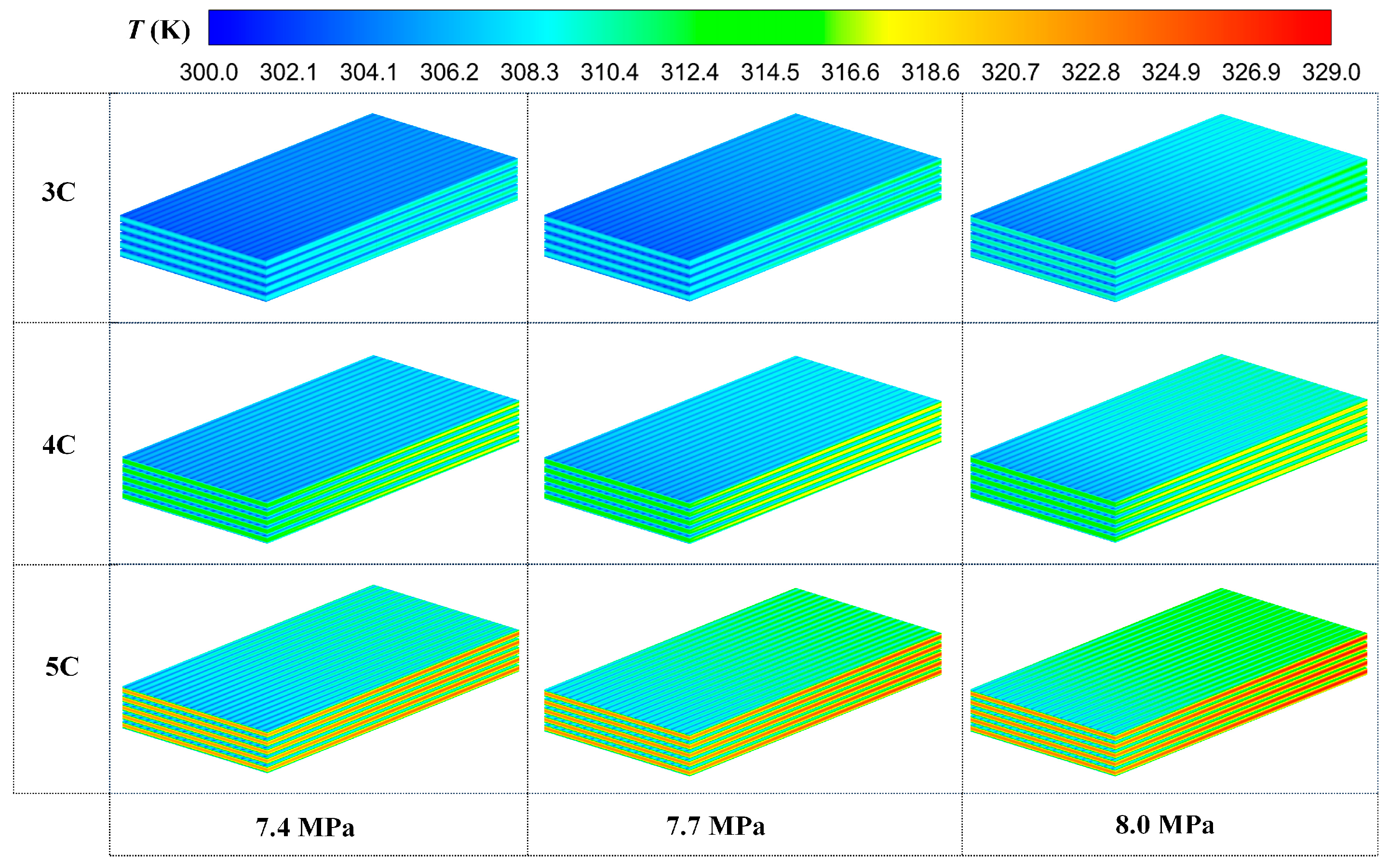
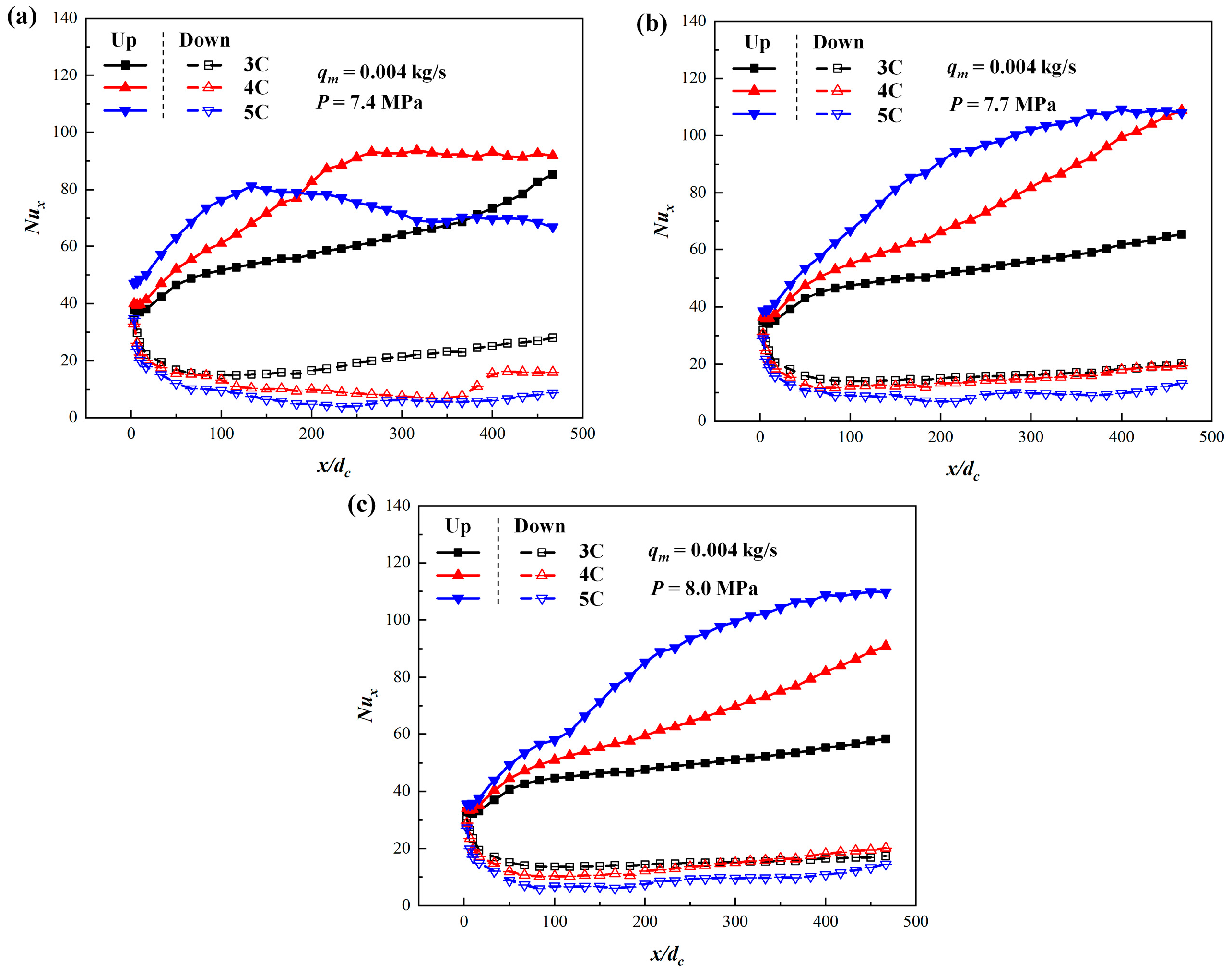
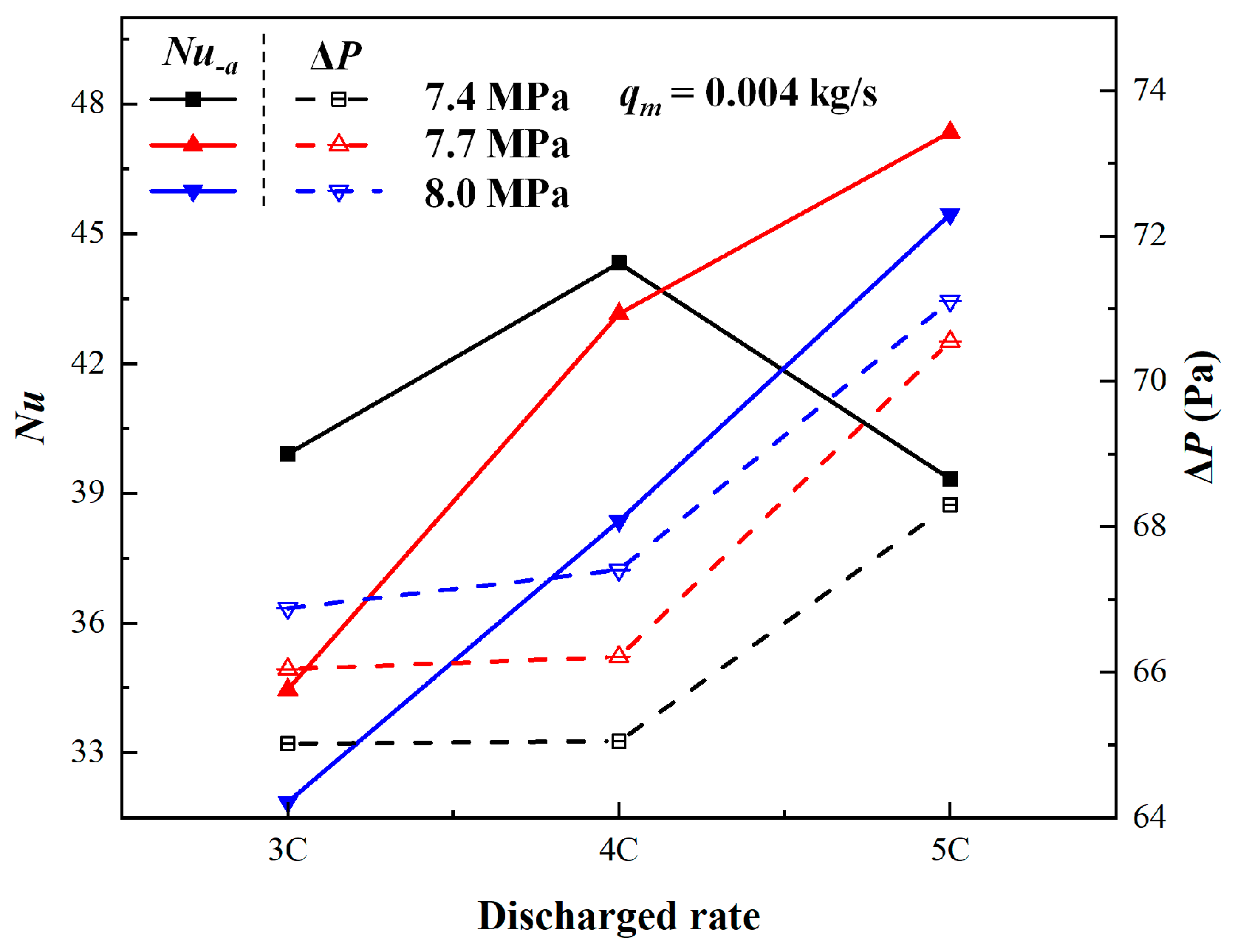
3.2. Comparison of Different Discharge Rates

The battery pack exhibits greater heat generation at higher discharge rates, which correspondingly influences the thermophysical properties of SCO2 under varying heat flux conditions. Figure 10 depicts the variations in the maximum temperature and the temperature difference in the battery with the different discharge rates. When the discharge rate increases from 3C to 5C, the maximum temperature of the battery pack rises by 13.75 K, 14.09 K, and 14.89 K at pressures of 7.4 MPa, 7.7 MPa, and 8.0 MPa, respectively. Concurrently, the temperature difference in the battery pack increases by 0.71 K, 0.54 K, and 0.68 K at these respective pressures.
The temperature distributions of the battery pack with different discharge rates are shown in Figure 11. As can be seen, the surface temperature of the battery increases with increases in the discharge rate. The lower the operational pressure, the lower the maximum temperature and the more uniform the temperature distribution. The heat dissipation effect and uniformity for the battery pack are optimized due to the operational pressure being close to the critical pressure, causing a higher specific heat peak.
Figure 12 illustrates how the local heat transfer characteristics of SCO2 vary with operating pressures and discharge rates. As the battery pack’s discharge rate increases, the accompanying rise in heat flux elevates the local Nusselt number. When the fluid temperature approaches the pseudo-critical point, significant density variations emerge due to radial temperature gradients, inducing buoyancy effects that create distinct heat transfer behaviors between upward and downward flows in the LCP. The intensification of radial temperature gradients with increasing discharge rates (from 3C to 5C) amplifies these characteristic differences. While enhanced heat flux generally improves heat transfer performance, a notable deterioration occurs in the upward flow at 7.4 MPa when the discharge rate exceeds 4C. This phenomenon stems from the more pronounced axial density variations near critical pressure, which promote flow laminarization through acceleration effects [39]. At the highest discharge rate of 5C, the acceleration effects become more dominant, further impairing heat transfer and causing the onset of thermal performance degradation to shift upstream to x/d = 100.
Figure 13 indicates that the average Nusselt number and pressure drop changed with the discharge rate. The pressure drop is increased upon increasing the discharge rate, and the lower the operating pressure, the smaller the pressure drop. Under the same conditions, the average Nusselt number increases when discharge rate increases, but it is reduced at 7.4 MPa and 5C.

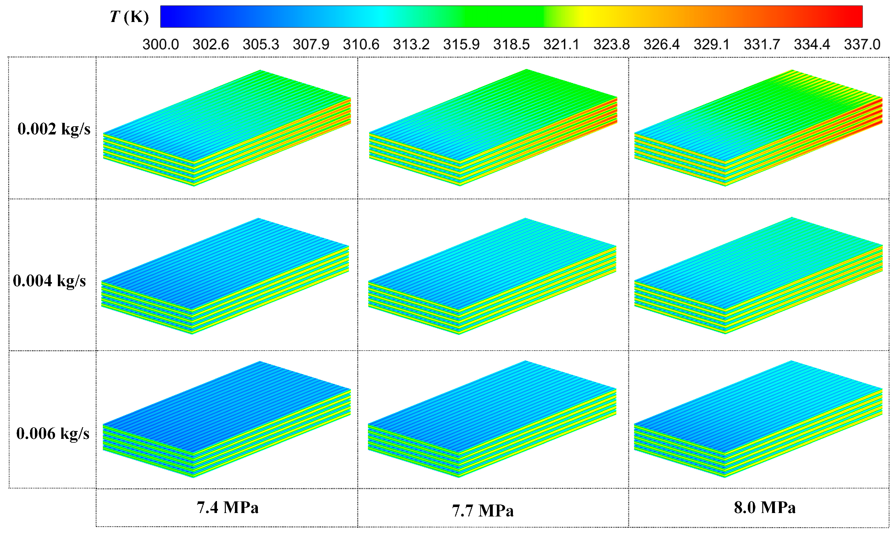
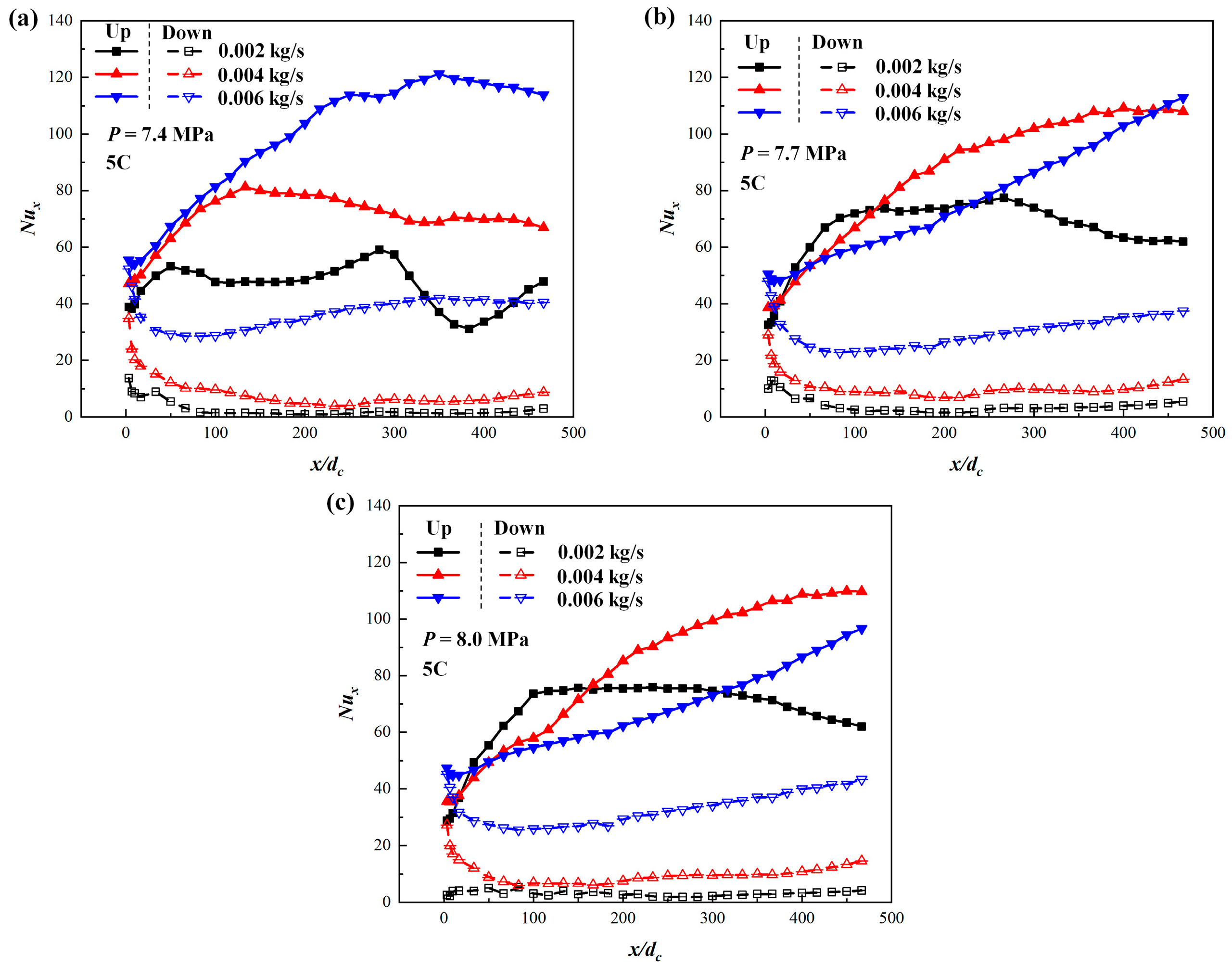
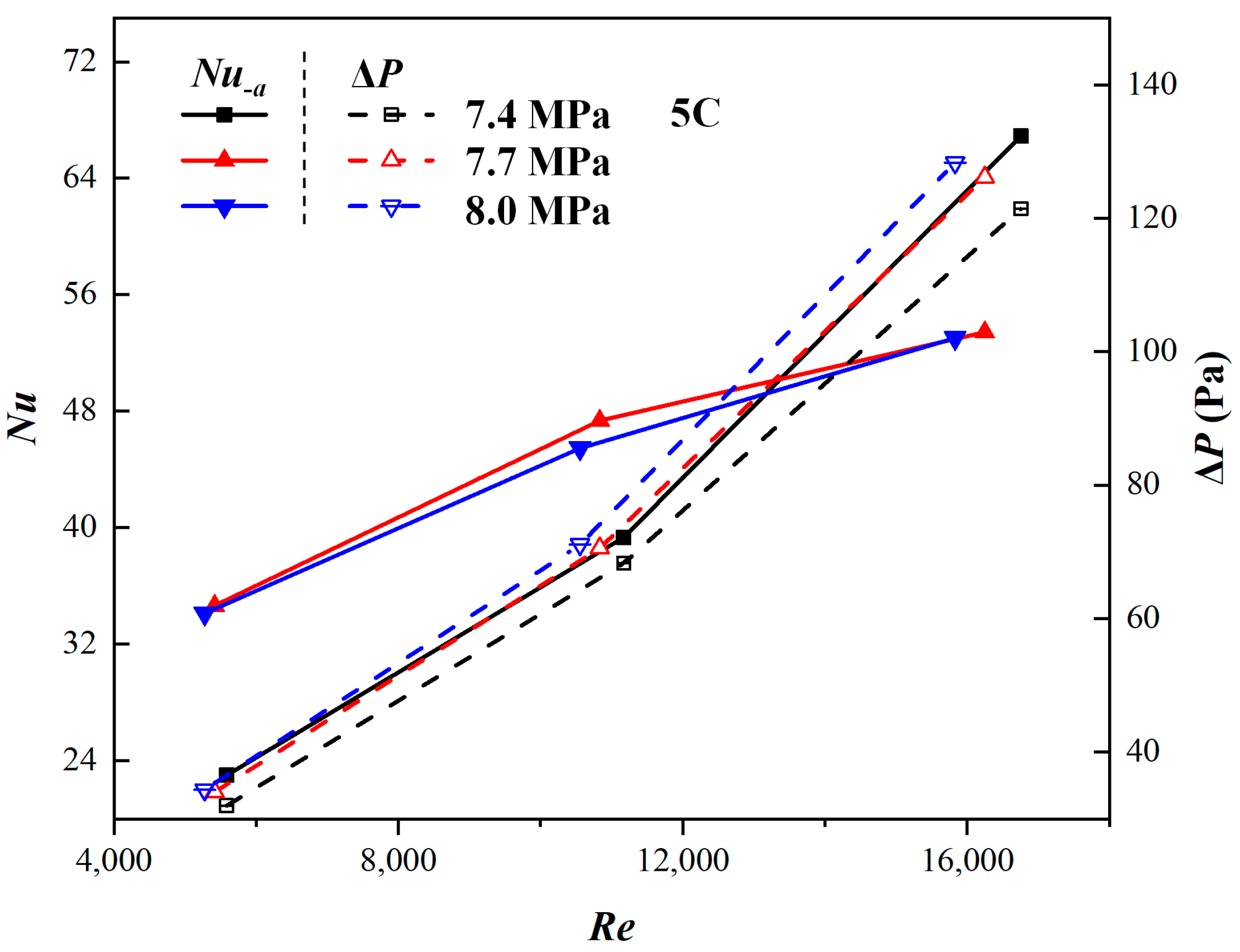
3.3. Comparison of Different Mass Flow Rates of Coolant

Figure 14 presents the results of the maximum temperature and the temperature difference with different mass flow rates at 5C. The maximum temperature and the temperature difference in the battery pack decrease with the increase in the mass flow rate. When the mass flow rate increases from 0.002 kg/s to 0.006 kg/s, for the pressures of 7.4 MPa, 7.7 MPa and 8.0 MPa, the maximum temperature reduces from 331.5 K, 334.1 K and 336.55 K to 323.49 K, 324.92 K and 326.28 K, respectively. The temperature difference reduces from 7.47 K, 9.18 K and 10.59 K to 2.38 K, 2.49 K and 3.38 K, respectively. However, the temperature of the battery pack is not reduced by a large margin upon increasing the mass flow rate. When the mass flow rate increases from 0.004 kg/s to 0.006 kg/s, the maximum temperature is reduced by 3.45% (1.8 K), 3.76% (1.92 K) and 3.9% (2.16 K), and the maximum temperature difference is reduced by 4.03% (0.1 K), 22.18% (0.61 K) and 17.35% (0.71 K), respectively. The improved thermal performance comes at the cost of significantly increased pumping power, which rises by at least 50% with the higher mass flow rates. Figure 15 shows the temperature distributions of the battery pack at the discharge rate of 5C with different mass flow rates. As can be seen, the maximum temperature of the battery pack is effectively reduced and the uniformity of temperature is obviously improved by increasing the mass flow rate.
The results in Figure 16 show that the variations in local heat transfer characteristics change with the mass flow rate. The effect of buoyancy results in differences in the heat transfer characteristics of the up and down flow of the LCP. For the down flow, the heat transfer characteristics are enhanced upon increasing the mass flow rate. For the up flow, the local Nusselt number is increased as the mass flow rate increases at an operational pressure of 7.4 MPa. It is worth noting that the local transfer characteristics begin to weaken with the mass flow rate of 0.002 kg/s at a certain position in the flow channel. The probable reason is that the effects of buoyancy and flow acceleration become more significant with the lower mass flow rate, causing a reduction in the Reynolds number. Furthermore, at elevated pressures of 7.7 MPa and 8.0 MPa with a mass flow rate of 0.004 kg/s, the local Nusselt number exhibits higher values, reflecting the complex interplay between forced convection, buoyancy, and flow acceleration under these conditions. These findings underscore the intricate coupling of competing thermal–hydraulic phenomena governing heat transfer in LCP systems.
The variations in the mean Nusselt number and pressure drop with the Reynolds number are presented in Figure 17. Regarding the results, the average Nusselt numbers are increased when the Reynolds number increases. At Reynolds numbers below Re = 10,000, the average Nusselt number is smaller at 7.4 MPa. However, for Re > 15,000, the average Nusselt number is higher than those at 7.7 MPa and 8.0 MPa. In contrast, the average Nusselt number at 7.7 MPa is slightly higher than that at 8.0MPa with different Reynolds numbers. Moreover, the Reynolds number increases also enhance the pressure drop, and the higher the operational pressure, the higher the pressure drop under the same conditions.

4. Conclusions

This study establishes a periodic model of the unit BTMS and employs numerical simulation to examine how different boundary conditions affect the battery pack’s heat dissipation performance. The investigation reveals the fundamental flow and heat transfer characteristics of SCO2 within the LCP under high battery discharge rate conditions. The main conclusions can be drawn as follows:
(1) This study demonstrates the superior thermal performance of SCO2 as a coolant in the BTMS compared to conventional water cooling. The experimental results show that SCO2 achieves significantly better heat dissipation while maintaining lower pressure drops. At a mass flow rate of 0.004 kg/s and 3C discharge rate, SCO2 cooling reduces the maximum temperature by 10% and temperature difference by 69.9% relative to water cooling. These improvements become even more pronounced at higher discharge rates, with 19.22% and 79.9% reductions in maximum temperature and temperature difference, respectively, at 5C. Furthermore, SCO2 exhibits substantially lower hydraulic resistance, with pressure drops in the LCP being 47% and 40.9% lower than those of water at 3C and 5C discharge rates, respectively, under identical operating conditions.
(2) When using the coolant of SCO2, the maximum temperature and the temperature difference in the battery pack increase upon increasing the discharge rate, and the pressure drop also is increased. The maximum temperature and the temperature difference in the battery pack decrease upon increasing the mass flow rate, but the pressure drop is increased. Under the same conditions, the lower the operational pressure, the better the heat dissipation effect and the smaller the pressure drop.
When employing SCO2 as the coolant, both the maximum temperature and temperature difference in the battery pack exhibit a positive correlation with the discharge rate while simultaneously experiencing an increased pressure drop. The maximum temperature and the temperature difference in the battery pack decrease upon increasing the mass flow rate, but the pressure drop is increased. Under the same conditions, the lower the operational pressure, the better the heat dissipation effect and the smaller the pressure drop. A comparative analysis reveals that lower operating pressures consistently provide enhanced thermal characteristics coupled with reduced hydraulic resistance under identical operating conditions.
(3) The effect of buoyancy causes a difference in the heat transfer characteristics of up and down flow in the LCP for the battery pack. The local Nusselt number in the channel does not increase axially. The local heat transfer shows a declining trend when the operational pressure and the mass flow rate are low and the discharge rate of the battery pack is large. The probable reason for this is that the effects of buoyancy and flow acceleration caused by the density of the fluid sharply drop due to the fluid temperature reaching a pseudo-critical temperature.

Author Contributions

Y.W.: administration, methodology, software, data curation, investigation, writing—original draft preparation. F.L.: supervision, validation. F.C.: supervision, validation. S.L.: writing—reviewing, supervision, validation. J.F.: writing—reviewing and editing, supervision, funding acquisition. All authors have read and agreed to the published version of the manuscript.

Funding

This work was supported by the National Natural Science Foundation of China (Grant No. 52276197), Gansu Province Key Research and Development Program-Industrial Project (Grant No. YFGA0069), National Science and Technology Major Project of China (J2019-III-0021-0065) and the Gansu Youth Science and Technology Fund (23JRRA827).

Data Availability Statement

The data presented in this study are available on request from the corresponding author.

Conflicts of Interest

Authors Ya Wang, Fengbim Li, Feng Cao were employed by the Sinohydro Engineering Bureau 4 Co., Ltd. The remaining authors declare that the research was conducted in the absence of any commercial or financial relationships that could be construed as a potential conflict of interest.

Abbreviations

The following abbreviations are used in this manuscript:
BTMSBattery thermal management system
ESSEnergy storage station
LCPLiquid cold plate
SCO2Supercritical carbon dioxide

References

  1. Darcovich, K.; MacNeil, D.D.; Recoskie, S.; Cadic, Q.; Ilinca, F. Comparison of Cooling Plate Configurations for Automotive Battery Pack Thermal Management. Appl. Therm. Eng. 2019, 155, 185–195. [Google Scholar] [CrossRef]
  2. Hannan, M.A.; Al-Shetwi, A.; Begum, R.A.; Young, S.E.; Hoque, M.M.; Ker, P.; Alzaareer, K. The Value of Thermal Management Control Strategies for Battery Energy Storage in Grid Decarbonization: Issues and Recommendations. J. Clean. Prod. 2020, 276, 124223. [Google Scholar] [CrossRef]
  3. Elaadouli, N.; Lajouad, R.; El Magri, A.; Mansouri, A.; Elmezdi, K. Adaptive Control Strategy for Energy Management in a Grid-Connected Battery Energy Storage System Using a Bidirectional Vienna Rectifier. J. Energy Storage 2024, 104, 114382. [Google Scholar] [CrossRef]
  4. Kalair, A.; Abas, N.; Saleem, M.S.; Kalair, A.R.; Khan, N. Role of Energy Storage Systems in Energy Transition from Fossil Fuels to Renewables. Energy Storage 2021, 3, e135. [Google Scholar] [CrossRef]
  5. Liu, H.; Wei, Z.; He, W.; Zhao, J. Thermal Issues about Li-Ion Batteries and Recent Progress in Battery Thermal Management Systems: A Review. Energy Convers. Manag. 2017, 150, 304–330. [Google Scholar] [CrossRef]
  6. Liu, B.; Jia, Y.; Yuan, C.; Wang, L.; Gao, X.; Yin, S.; Xu, J. Safety Issues and Mechanisms of Lithium-Ion Battery Cell upon Mechanical Abusive Loading: A Review. Energy Storage Mater. 2020, 24, 85–112. [Google Scholar] [CrossRef]
  7. Borah, R.; Hughson, F.R.; Johnston, J.; Nann, T. On Battery Materials and Methods. Mater. Today Adv. 2020, 6, 100046. [Google Scholar] [CrossRef]
  8. Shahjalal, M.; Shams, T.; Islam, M.E.; Alam, W.; Modak, M.; Hossain, S.B.; Iqbal, A. A Review of Thermal Management for Li-Ion Batteries: Prospects, Challenges, and Issues. J. Energy Storage 2021, 39, 102518. [Google Scholar] [CrossRef]
  9. Ahmed, D.; Ebeed, M.; Ali, A.; Alghamdi, A.S.; Kamel, S. Multi-Objective Energy Management of a Micro-Grid Considering Stochastic Nature of Load and Renewable Energy Resources. Electronics 2021, 10, 403. [Google Scholar] [CrossRef]
  10. Xie, J.; Ge, Z.; Zang, M.; Wang, S. Structural Optimization of Lithium-Ion Battery Pack with Forced Air Cooling System. Appl. Therm. Eng. 2017, 126, 583–593. [Google Scholar] [CrossRef]
  11. Lebrouhi, B.E.; Khattari, Y.; Lamrani, B.; Maaroufi, M.; Zeraouli, Y.; Kousksou, T. Key Challenges for a Large-Scale Development of Battery Electric Vehicles: A Comprehensive Review. J. Energy Storage 2021, 44, 103273. [Google Scholar] [CrossRef]
  12. Li, Y.; Du, Y.; Xu, T.; Wu, H.; Zhou, X.; Ling, Z.; Zhang, Z. Optimization of Thermal Management System for Li-Ion Batteries Using Phase Change Material. Appl. Therm. Eng. 2018, 131, 766–778. [Google Scholar] [CrossRef]
  13. Ling, Z.; Wang, F.; Fang, X.; Gao, X.; Zhang, Z. A Hybrid Thermal Management System for Lithium-Ion Batteries Combining Phase Change Materials with Forced-Air Cooling. Appl. Energy 2015, 148, 403–409. [Google Scholar] [CrossRef]
  14. Weragoda, D.M.; Tian, G.; Burkitbayev, A.; Lo, K.H.; Zhang, T. A Comprehensive Review on Heat Pipe Based Battery Thermal Management Systems. Appl. Therm. Eng. 2023, 224, 120070. [Google Scholar] [CrossRef]
  15. Mei, N.; Xu, X.; Li, R. Heat Dissipation Analysis on the Liquid Cooling System Coupled with a Flat Heat Pipe of a Lithium-Ion Battery. ACS Omega 2020, 5, 17431–17441. [Google Scholar] [CrossRef]
  16. Xia, G.; Cao, L.; Bi, G. A Review on Battery Thermal Management in Electric Vehicle Application. J. Power Sources 2017, 367, 90–105. [Google Scholar] [CrossRef]
  17. Tan, X.; Lyu, P.; Fan, Y.; Rao, J.; Ouyang, K. Numerical Investigation of the Direct Liquid Cooling of a Fast-Charging Lithium-Ion Battery Pack in Hydrofluoroether. Appl. Therm. Eng. 2021, 196, 117279. [Google Scholar] [CrossRef]
  18. Zhang, T.; Gao, Q.; Wang, G.; Gu, Y.; Wang, Y.; Bao, W.; Zhang, D. Investigation on the Promotion of Temperature Uniformity for the Designed Battery Pack with Liquid Flow in Cooling Process. Appl. Therm. Eng. 2017, 116, 655–662. [Google Scholar] [CrossRef]
  19. Xu, J.; Guo, Z.; Xu, Z.; Zhou, X.; Mei, X. A Systematic Review and Comparison of Liquid-Based Cooling System for Lithium-Ion Batteries. eTransportation 2023, 17, 100242. [Google Scholar] [CrossRef]
  20. Hall, W.B. Heat Transfer near the Critical Point. In Advances in Heat Transfer; Elsevier: Amsterdam, The Netherlands, 1971; Volume 7, pp. 1–86. [Google Scholar]
  21. Austin, B.T.; Sumathy, K. Transcritical Carbon Dioxide Heat Pump Systems: A Review. Renew. Sustain. Energy Rev. 2011, 15, 4013–4029. [Google Scholar] [CrossRef]
  22. Huang, Y.; Wang, J. Application of Supercritical Carbon Dioxide in Nuclear Reactor System. Nucl. Power Eng. 2012, 33, 21–27. [Google Scholar]
  23. Li, H.; Zhang, Y.; Zhang, L.; Yao, M.; Kruizenga, A.; Anderson, M. Based Modeling on the Turbulent Convection Heat Transfer of Supercritical CO2 in the Printed Circuit Heat Exchangers for the Supercritical CO2 Brayton Cycle. Int. J. Heat Mass Transf. 2016, 98, 204–218. [Google Scholar] [CrossRef]
  24. Khalesi, J.; Sarunac, N. Numerical Analysis of Flow and Conjugate Heat Transfer for Supercritical CO2 and Liquid Sodium in Square Microchannels. Int. J. Heat Mass Transf. 2019, 132, 1187–1199. [Google Scholar] [CrossRef]
  25. da Rosa, O.C.; Battisti, F.G.; Hobold, G.M.; da Silva, A.K. Enhancing Heat Rejection from Electronic Devices with a Supercritical Carbon Dioxide Minichannel Heat Exchanger. Int. J. Refrig. 2019, 106, 463–473. [Google Scholar] [CrossRef]
  26. Huang, H.; Zhai, Y.; Li, Z.; Wang, H. Thermo-Hydraulic Characteristics and Structural Optimization of Supercritical CO2-Cooled Microchannel Heat Sink. Int. Commun. Heat Mass Transf. 2024, 154, 107438. [Google Scholar] [CrossRef]
  27. Huang, H.; Zhai, Y.; Li, Z.; Li, Y.; Wang, H. Thermal Management for Microelectronic Chips under Non-Uniform Heat Flux with Supercritical CO2. Int. J. Heat Mass Transf. 2025, 236, 126271. [Google Scholar] [CrossRef]
  28. Khan, S.A.; Ahmad, S.; Lau, K.T.; Dong, K.; He, S.; Liu, H.; Zhao, J. A Novel Strategy of Thermal Management System for Battery Energy Storage System Based on Supercritical CO2. Energy Convers. Manag. 2023, 277, 116676. [Google Scholar] [CrossRef]
  29. Yang, Y.; Wu, J.; Song, X.; Gu, Z. Thermal Management Performance of Lithium-Ion Battery Using Supercritical CO2 as Cooling Fluid. Heat Transf. Eng. 2023, 44, 1452–1465. [Google Scholar] [CrossRef]
  30. Fan, Y.; Wang, Z.; Fu, T.; Wu, H. Numerical Investigation on Lithium-Ion Battery Thermal Management Utilizing a Novel Tree-Like Channel Liquid Cooling Plate Exchanger. Int. J. Heat Mass Transf. 2022, 183, 122143. [Google Scholar] [CrossRef]
  31. Li, B.; Wang, W.; Bei, S.; Quan, Z. Analysis of Heat Dissipation Performance of Battery Liquid Cooling Plate Based on Bionic Structure. Sustainability 2022, 14, 5541. [Google Scholar] [CrossRef]
  32. Ding, Y.; Ji, H.; Wei, M.; Liu, R. Effect of Liquid Cooling System Structure on Lithium-Ion Battery Pack Temperature Fields. Int. J. Heat Mass Transf. 2022, 183, 122178. [Google Scholar] [CrossRef]
  33. Deng, T.; Zhang, G.; Ran, Y.; Liu, P. Thermal Performance of Lithium-Ion Battery Pack by Using Cold Plate. Appl. Therm. Eng. 2019, 160, 114088. [Google Scholar] [CrossRef]
  34. Khoshvaght-Aliabadi, M.; Zakizadeh-Matak, T. Mechanism Analysis of Turbulent Convective Heat Transfer of Supercritical Carbon Dioxide in Serpentine Tubes. Appl. Therm. Eng. 2024, 257, 124490. [Google Scholar] [CrossRef]
  35. Fu, J.; Liu, H.Y.; Wang, Y. Numerical Analysis of Mechanism on Heat Transfer Deterioration of Hexamethyldisiloxane in a Vertical Upward Tube at Supercritical Pressures. J. Appl. Fluid Mech. 2024, 17, 1967–1980. [Google Scholar]
  36. Xu, X.; Tong, G.; Li, R. Numerical Study and Optimizing on Cold Plate Splitter for Lithium Battery Thermal Management System. Appl. Therm. Eng. 2020, 167, 114787. [Google Scholar] [CrossRef]
  37. Huang, D.; Li, W. A Brief Review on the Buoyancy Criteria for Supercritical Fluids. Appl. Therm. Eng. 2018, 131, 977–987. [Google Scholar] [CrossRef]
  38. Jackson, J.D. Models of Heat Transfer to Fluids at Supercritical Pressure with Influences of Buoyancy and Acceleration. Appl. Therm. Eng. 2017, 124, 1481–1491. [Google Scholar] [CrossRef]
  39. Kim, T.H.; Kwon, J.G.; Kim, M.H.; Park, H.S. Experimental Investigation on Validity of Buoyancy Parameters to Heat Transfer of CO2 at Supercritical Pressures in a Horizontal Tube. Exp. Therm. Fluid Sci. 2018, 92, 222–230. [Google Scholar] [CrossRef]
Figure 1. Schematic of battery and cooling system model.
Energies 18 02030 g001
Figure 2. Variations in thermal physical properties of SCO2 with temperature and pressure.
Energies 18 02030 g002
Figure 3. Mesh generated in the battery and cooling system.
Energies 18 02030 g003
Figure 4. Results of simulations performed for mesh independence tests.
Energies 18 02030 g004
Figure 5. Validation of numerical simulation.
Energies 18 02030 g005
Figure 6. Maximum temperature and temperature difference in battery with different coolants: qm = 0.004 kg/s, and temperature difference 3C and 5C.
Energies 18 02030 g006
Figure 7. Temperature distributions of battery with different coolants: (a) qm = 0.004 kg/s, 3C; (b) qm = 0.004 kg/s, 5C.
Energies 18 02030 g007
Figure 8. Effects of different coolants on the local heat transfer characteristics and flow characteristics: (a) heat transfer characteristics, qm = 0.004 kg/s, 3C; (b) flow characteristics, qm = 0.004 kg/s, 3C; (c) heat transfer characteristics, qm = 0.004 kg/s, 5C; (d) flow characteristics, qm = 0.004 kg/s, 5C.
Energies 18 02030 g008
Figure 9. Pressure drops with different coolants: qm = 0.004 kg/s, 3C and 5C.
Energies 18 02030 g009
Figure 10. Maximum temperature and temperature difference in battery with different discharge rates: qm = 0.004 kg/s.
Energies 18 02030 g010
Figure 11. Temperature distributions of battery pack with different discharge rates: qm = 0.004 kg/s.
Energies 18 02030 g011
Figure 12. Effects of discharge rate on local heat transfer characteristics: (a) P = 7.4 MPa, qm = 0.004 kg/s; (b) P = 7.7 MPa, qm = 0.004 kg/s; (c) P = 8.0 MPa, qm = 0.004 kg/s.
Energies 18 02030 g012
Figure 13. Effects of discharge rate on average Nusselt number and pressure drop.
Energies 18 02030 g013
Figure 14. Maximum temperature and temperature difference in battery with different mass flow rates.
Energies 18 02030 g014
Figure 15. Temperature distributions of battery pack with different mass flow rates of coolant.
Energies 18 02030 g015
Figure 16. Effects of mass flow rate of coolant on local heat transfer characteristics: (a) P = 7.4 MPa, 5C; (b) P = 7.7 MPa, 5C; (c) P = 8.0 MPa, 5C.
Energies 18 02030 g016
Figure 17. Effects of the mass flow rate of the coolant on the average Nusselt number and the pressure drop.
Energies 18 02030 g017
Table 1. Specifications of battery and LCP.
SpecificationsDetails
Battery
MaterialLiFePO4
Dimension 148 × 27.5 × 91 mm
Nominal capacity40 Ah
Nominal voltage 3.2 V
Density2160 kg/m3
Specific heat1129 J/kg·K
Cold plate
Density 7980 kg/m3
Specific heat500 J/kg·K
Thermal conductivity 16.3 W/m·K
Table 2. Test matrix of LCP.
Discharge Rates (C)Mass Flow Rates (kg/s)Operational Pressure (MPa)
30.0027.4
40.0047.7
50.0068.0
Disclaimer/Publisher’s Note: The statements, opinions and data contained in all publications are solely those of the individual author(s) and contributor(s) and not of MDPI and/or the editor(s). MDPI and/or the editor(s) disclaim responsibility for any injury to people or property resulting from any ideas, methods, instructions or products referred to in the content.

