Article

A Neutron Source Based on Spherical Tokamak

1
ENEA Nuclear Department, C.R. Frascati, via E Fermi 45, 00044 Frascati, Italy
2
ENEA Nuclear Department, C.R. Casaccia, via Anguillarese 301, S. Maria di Galeria, 00123 Roma, Italy
3
GeNERG, Dipartimento di Ingegneria Meccanica, Energetica, Gestionale e dei Trasporti, Università di Genova, 16145 Genova, Italy
4
INFN Sezione di Genova, via Dodecaneso 33, 16146 Genova, Italy
*
Authors to whom correspondence should be addressed.
Energies 2025, 18(8), 2029; https://doi.org/10.3390/en18082029
Submission received: 30 December 2024 / Revised: 22 March 2025 / Accepted: 2 April 2025 / Published: 15 April 2025
(This article belongs to the Special Issue Advanced Technologies in Nuclear Engineering)

Abstract

:
The paper presents a conceptual study of a neutron source based on a spherical tokamak (ST). The plasma scenario chosen for the ST is non-thermal fusion (hot ion mode), which is extensively used on machines like JET and TFTR deuterium–tritium (DT) experiments, which seems suited for low fusion gain reactors. As demonstrated in experiments, this scenario is a robust tool for neutron production. Starting from a new scaling law of energy confinement tested, approximately, on ST40 spherical tokamak, the parameters of a 15 MW ST DT fusion reactor (ST180) are derived, and a preliminary radial build of the machine is established.

1. Introduction

The progress on the physics and technology of fusion devices has led, in recent years, to studies on the possibility of building neutron sources based on fusion. In the context of Magnetic Confinement Fusion (MCF), various magnetic configurations have been considered, including mirrors, conventional tokamaks (CT) with aspect ratios of A ≥ 3, spherical tokamaks with aspect ratios of A ≤ 2, and other configurations.
Research on fusion devices not optimized for electrical power production is gaining more and more interest [1,2,3]. The need to build neutron sources for testing materials that are resistant to high neutron fluxes has been identified as a high priority R&D subject for fusion reactor development [4]. In addition, these sources can be useful for driving fusion–fission hybrid reactors (FFHR) [5,6].
In fact, a neutron source for FFHR can be compact and, using a non-thermal D-T (deuterium–tritium) plasma scenario, is optimal for neutron production with low fusion gain (Q). The technology needed to build this neutron source is available; both high temperature superconducting magnets as well as heating system (neutral beam sources and Ion cyclotron resonance heating systems) technologies have been tested on devices in operation. Therefore, projects studying compact ST neutron sources optimized for low Q are important, because the available fusion technology could be used to build a pilot FFHR plant.
An ST (spherical tokamak) has a compact geometry, relatively good confinement, and MHD stability. The key point here is the use of a new confinement scaling law for non-thermal plasmas, obtained by merging results from the experiments on TFTR and preliminarily validated on ST40. This makes the design quite innovative. The statement of the problem developed here can be as follows: is it possible to determine the plasma parameters of a tokamak neutron source optimized for neutron production at low Q fusion gain, and its layout? In this paper, a project involving a neutron source based on ST is presented, using the following arguments:
(i).
The non-thermal plasma scenario has been demonstrated as a solid tool for plasma operation, as record fusion power was obtained in the JET DTE2 campaign [7,8,9], and it was studied intensively on TFTR [10] and JET DTE1 [11]; the same scenario has been used to obtain a record ion temperature in ST40 in deuterium plasma [12]; it is the optimized scenario for low Q [13] operation.
(ii).
A new scaling law for the confinement time of the non-thermal scenario has been preliminarily validated on ST40 [14]; it improves the previous scaling, including the plasma geometry and density peaking dependences found in experiments [10,15].
(iii).
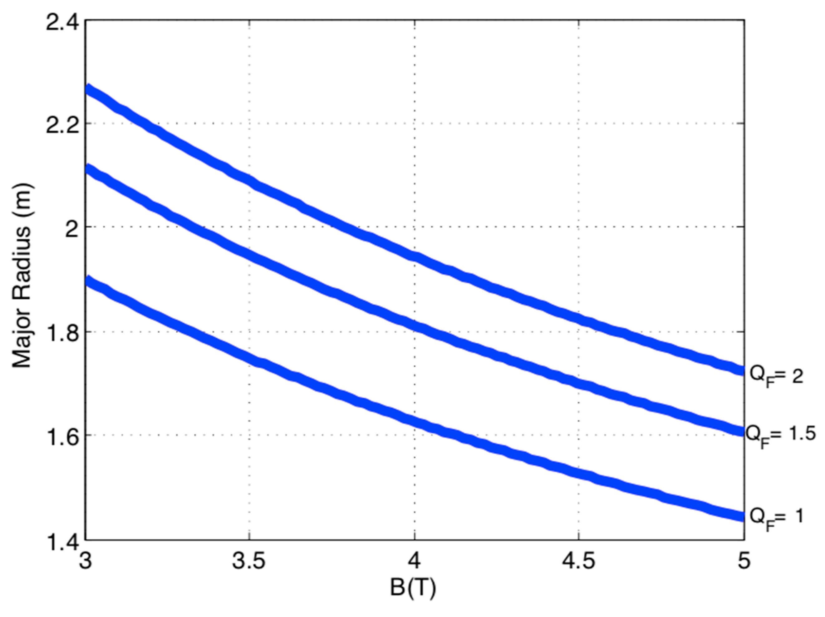
Using the previous points and the method described in Section 3, an elaboration of the scaling law, which gives the major radius versus the magnetic field, can be performed, leading to the determination of the plasma parameters of a Q = 1.5 ST neutron source (named ST180, R = 180 cm, Aspect Ratio A = 1.8, B = 4 T).
(iv).
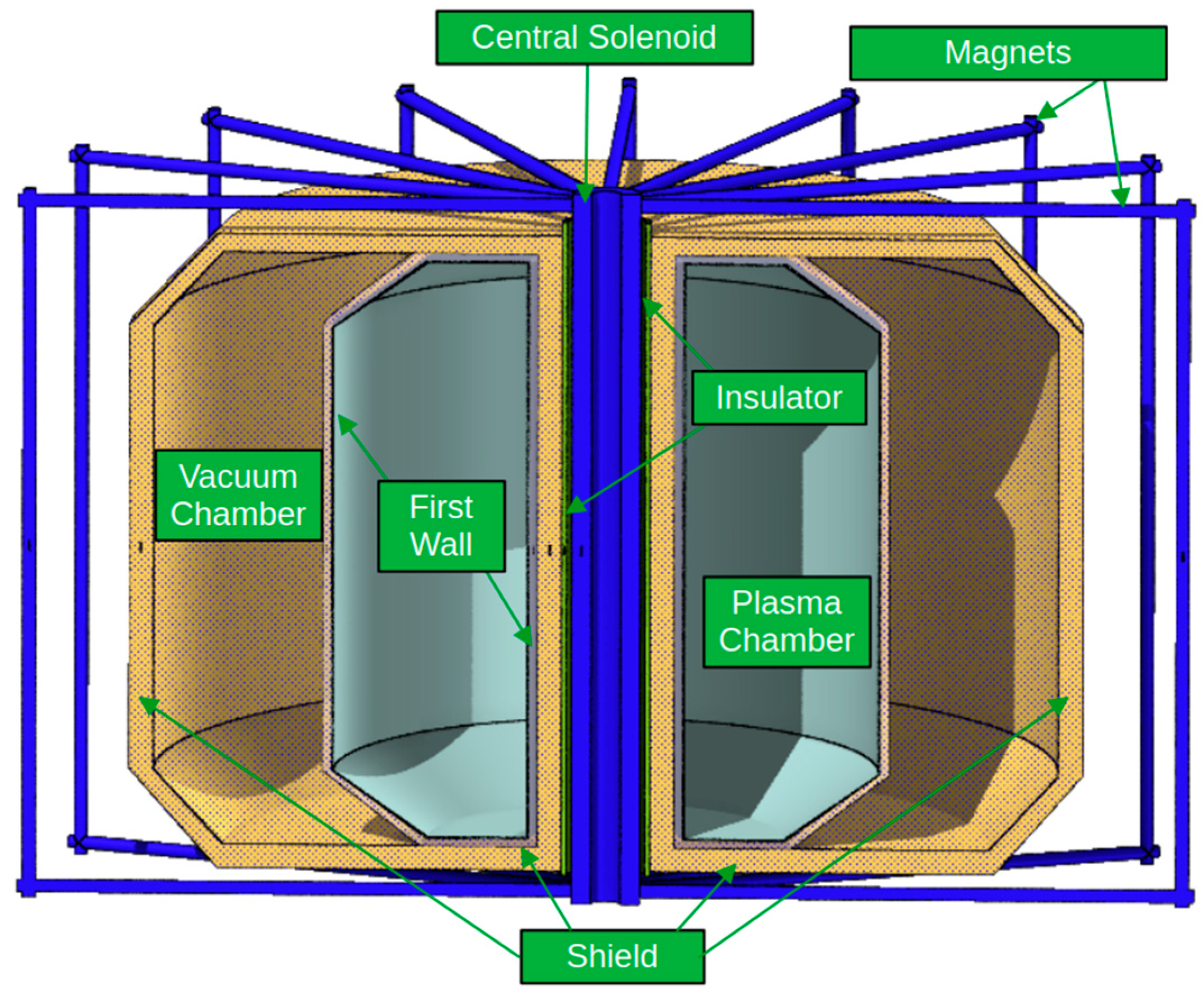
Based on the plasma parameters determined, the layout of ST180 tokamak is determined, defining the structural components as well: due to the high neutron flux, the problem of shieldings, which are useful for protecting the superconducting magnets, is solved using (Zr(BH4)4,W) [16,17,18]. The pulse length evaluated from the available flux swing is 58 s, and possible continuous operation of ST180 in the chosen plasma scenario is only limited by the recharging time of the main solenoid.
(v).
The ST180 neutron source can be considered suitable for FFHR realization because, using the non-thermal scenario, it is optimized for low fusion gain factors.
Now, we move to a short description of the general context of the status of the research on the tokamak.
In the context of tokamaks, arguments based on the confinement and stability properties of spherical tokamaks (ST) elevated these machines as compact, high-intensity neutron source candidates [19]. The plasma scenarios considered in [19] were the conventional high-confinement mode (H-mode) for the CT [20] or the NSTX-extended mode for the ST [19,21]. In this context, one of the results of [19] is that, at a fixed fusion power, the ST allows for a higher fusion gain with respect to CT.
Recently, record ion temperature results in ST40 spherical tokamak were obtained using a (so called) hot-ion (or non-thermal; in this paper, both names are used with reference to the same scenario) mode plasma scenario [12]: ion temperatures, Ti ≈ 9–10 keV, were obtained in deuterium plasmas. These plasmas are characterized by Ti >> Te and the heat thermal losses were dominated by electrons, while the ion thermal conduction was much lower than that of the electrons. The triple product estimated was ni Ti τE = 6 ± 2 × 10¹⁸ keV m−3 s (ni = ion density, Ti = ion temperature, and τE = energy confinement time).
The hot-ion mode scenario is obtained by direct fusion reaction of supra-thermal ions injected into a plasma interacting directly with plasma thermal ions. This configuration increases the neutron flux, because the fusion reaction is obtained with optimal fusion cross section values: the DT cross section has a maximum deuterium energy of about 100 keV [22].
We consider, therefore, a neutron source made by a ST with an aspect ratio of A = 1.8, based on non-thermal fusion. Actually, the present record of fusion production obtained on JET in DTE2/3 was obtained using a non-thermal plasma scenario, where deuterium beams with 130 keV energy were fired on tritium-rich DT plasma (25% deuterium, 75% tritium) [7,9]. The non-thermal plasma scenario is optimized for low fusion gain Q (proportional to triple product nTτ) devices, because it maximizes the neutron production at a relatively low value of the product n·τE [13].
Therefore, the a DT (deuterium–tritium) compact neutron source based on ST which uses a hot-ion mode plasma scenario with low fusion gain factor (Q ≤ 3) is the subject analyzed for the first time in the present paper.
The paper is organized as follows:
  • In Section 2, the non-thermal plasma scenario with a spherical tokamak with low fusion gain factor and a new confinement scaling law are introduced;
  • In Section 3, the scaling laws for spherical tokamaks are obtained, and the results are used to determine the plasma parameters of a low gain spherical fusion reactor, named ST180, which is useful as neutron source;
  • In Section 4, the fusion power of ST180 non-thermal plasma is evaluated;
  • In Section 5, the radial build-up of ST180 is briefly described;
  • In Section 6, conclusions are drawn.

2. Non-Thermal Plasma Scenario for Spherical Tokamaks

The non-thermal plasma scenario (called ‘supershots’ on TFTR [10] or ‘hot-ion mode’ on JET [7,11]) is considered the ideal scenario for low Q (fusion gain) machines; see Figure 23 in [13]. Furthermore, a new ‘supershot-like’ scaling law of confinement has tested positively on ‘hot-ion mode’ discharges of the ST40 spherical tokamak [14].
The scaling law of energy confinement time is
τ TFTR ( s ) = 0.048   Ip 0.22   Bt   W Beam 0.56   R 1.83   A 0.06   k 0.64   n < n > 1 . 5   n 0 . 4
where the plasma geometry (major radius R, aspect ratio A = major radius/minor radius, elongation k), the magnetic field on axis Bt, the plasma current Ip, the density peaking (n/<n> = central plasma density/volume average plasma density), and beam energy (Wbeam) are included. The scaling law (1) was obtained by merging the TFTR supershots’ confinement time scaling (see [10], Equation (24)) and the L-mode scaling [20], which contains the plasma geometry.
In the Formula (1) the dependence of the confinement time on the isotopic mass (M) is neglected as the L-mode scaling exhibits a very slow dependence (M0.20). The proportionality constant in (1) is preliminarily evaluated as 0.048 [14].
Therefore, Equation (1) describes complex plasmas where the heating beam is deuterium and the target plasma is mainly tritium: the main fusion reactions (and then the neutron emission) are connected to the direct interaction of the beam with thermalized tritium ions present in the plasma. In the scaling law (1), the dependence on carbon light emission (which appears in the original TFTR confinement scaling [10]) is omitted, because it was related to the wall composition; the isotopic composition of the plasma is also not included. The beam geometry, i.e., the ratio between the co-injected power (in the direction of axial magnetic field) and the total power, which appears in the original formulation of TFTR confinement scaling, is not included in the scaling (1). The density peaking scaling is taken from Figure 5 in [15], where it is remarked that the density peaking could be linked to a transport property of the TFTR supershots. Finally, it is important to note that the confinement time in (1) is related to the total plasma energy, which includes mainly beam target reactions, so the produced alpha particle slowing down is important in this context as well as the collisional relaxation of beams on plasma ions.
The additional motivation for using the non-thermal supershot scenario is that it is relatively easy to realize, and particularly resilient to any plasma instability. The supershot plasma scenario is a good candidate for a neutron source: it needs a neutral beam heating system or a ICRH (ion-cyclotron resonance heating system) which can be used for the acceleration of plasma ions to energies higher than (or of the order of) 100 keV.
The scaling in (1) is new and different from the different forms of scaling in energy confinement presently used for the L-mode (low confinement mode [20]), the H-mode (high confinement mode [20]), and the improved NSTX scaling used for the ST confinement [1,19]. It is specifically developed for non-thermal plasmas, heated by neutral beams, and/or fast ions generated by ICRH heating. It is based on the TFTR experimental data and retains the L-mode nature of the non-thermal plasma confinement.

3. Scaling Law for Spherical Tokamak Fusion Reactors in Non-Thermal Supershot-like Scenario

The method outlined in [14,21] can be used to obtain the scaling law for spherical fusion reactors working in a supershot-like scenario. We start with the working conditions useful for defining the plasma state of a fusion reactor [21]:
(i).
The reactor is working at a value of Q0 = ni τE Ti, where ni is the ion density, Ti the ion temperature, and τE the energy confinement time given by Equation (1)
(ii).
The alpha particle slowing down time (τSD) must be less than the energy confinement time; i.e., τSD = ΛSD τE, where ΛSD << 1 is a number
To make the derivation of the scaling law easier, additional simplifying assumptions are carried out, as follows: ni = ne, the electron density is equal to the ion density (which means that the impurities and the helium dynamics are not considered), and Ti ≥ Te (Te electron temperature), the ion temperature is not much higher than the electron temperature. In practice this second condition means that the alpha particles produced in this scenario give their energy mainly to electrons and the fraction of energy given by alpha particles to ions cannot be considered high. But, with the working plasma density being sufficiently high, the electron temperature is not much lower than Ti. Considering that τSD = ASD Te3/2/ne (ne = electron density, ASD = dimensional constant [22]), we obtain the relation between the electron temperature and the product of the confinement time and the density (from now on, ne = ni = n)
Te = Λ SD ASD 2 / 3   n   τ E 2 / 3
On the other side, since Ti ≥ Te, we can consider the following condition (which is obtained from the condition i) valid, substituting Ti ≈ Te =T):
n   τ E T = Λ S D A S D 2 / 3   n   τ E 5 / 3
we obtain a scaling law expressing the major radius versusthe plasma and geometry parameters, substituting in (3) the expression of the confinement time given by (1):
R           Q 0 0.33     Λ SD ASD 0 . 22   n 0 . 75   Bt 0 . 54   f 0 . 54   ; f 0 . 54 = Ip 0 . 12     W beam 0.3     A 0.03       k 0.34       n < n > 0.81
The values of the plasma major radius of a spherical fusion reactor can be obtained if we introduce a calibration constant in (4) using the TFTR supershot parameters obtained from [10], as follows: major radius, R = 2.52 m; minor radius, a = 0.87; magnetic field, Bt = 5.1 T; plasma current, Ip = 2.1 MA; elongation, k = 1; plasma density, n = 8 × 10¹⁹ m−3; aspect ratio, A = 2.86; beam energy, WB = 105 keV; density peaking factor, n/<n> = 2; QFus = 0.135. In this way, the plot reported in Figure 1 is obtained, where the major radius is given versus the magnetic field Bt for fusion gain factors; QFus = 1, 1.5, 2. The relation between QFus and Q0 is given by the following equation:
Q 0 = 1 C F 5 Q FUS 5 + Q FUS     ;     Q FUS = P FUS P H
where PFus is the fusion power and PH is the heating power external to the plasma, and CF is a dimensional constant.
From Figure 1, the following plasma parameters for a QFus = 1.5 spherical tokamak, named ST180, can be derived:
  • R = 1.8 m;
  • A = 1.8;
  • Ip = 6 MA;
  • B = 4 T;
  • N = 10·1019 m−3;
  • n/<n> = 3.5;
  • elongation k = 2.9;
  • beam energy WB = 80 keV.
The dimensions of the ST180 project are greater than all the STs built so far, as shown in Table 1.
The STs appearing in Table 1, ST40, MAST-U and GLOBUS-M2 are in operation and work in deuterium, producing 2.5 MeV neutrons in the range of 1013–1015 n/s intensity. The ST180 device is designed to operate in a D-T (deuterium–tritium) gas mixture with a composition of D:T/25:75, to obtain the non-thermal scenario, producing 14 MeV neutrons, at 5 × 10¹⁸ n/s intensity.
The data from ST40 were analyzed to obtain the normalization coefficient of the scaling law of energy confinement on a broad database. The value of the experimental confinement time was compared with the scaling law for ne = 4–14 × 1019 m−3; input heating power, PNBI = 1.5–2 MW; and plasma current, Ip = 0.4–0.6 MA. A slow dependence of the confinement time upon PNBI and plasma current was found, along with a clear dependence on the plasma density, in agreement with the results of TFTR. The scaling law obtained from ST40 data was also checked on the published TFTR confinement time data.
As demonstrated on JET [7], non-thermal plasmas can be operated with NBI and ICRH, profiting on fast ion acceleration (by ICRH) [8]. A study of the ST180-like machine using a system code (for example PROCESS [27]) will be a natural development of this analysis.

4. Fusion Power Evaluation for Non-Thermal Plasmas

The fusion power evaluation for non-thermal plasmas needs some elaboration. The plasma scenario is characterized by fusion reactions produced by the deuterium beams reacting directly on the tritium plasma target. The plasma reactivity, RDT, is given by the following general expression [22]:
R DT = σ ( v D v T )     v D v T   f D ( v D )   f T ( v T )   d 3 v D   d 3 v T
where vD and vT are the deuterium and tritium velocities, and fi are the velocity distribution functions.
The ion velocity functions are given by the following expressions:
f i = n i   b i π 3 / 2   exp ( b i   v i 2 )   ;     b i = m i 2 T i
In this scenario the deuterium ions have a velocity much higher than the plasma tritium ions; following this hypothesis, the plasma reactivity can be approximated roughly as:
R DT = σ ( v D )   v D f D ( v D )   d 3 v D f T ( v T )     d 3 v T n T σ   ( v D )   v D f D ( v D )   d 3 v D  
The fusion power Pfus produced in the plasma volume V is given by the expression:
P FUS = R DT   dV       E FUS
where the integration is extended to the plasma volume and Efus = 17.6 MeV is the total energy of one fusion reaction.
The fusion cross section versus the incident ion deuterium velocity can be parametrized using a 4th degree polynomial through the following expression:
σ = 1 5 p k   V D 5 k
where pk are coefficients of a fit to the cross section.
The expression of the reactivity can be rewritten as
R DT = n T     σ ( v D )   v D   f D ( v D )   d 3 v D = = n D   n T   b D π 3 / 2     1 5 p k v D 5 k + 3   exp ( b D   v D 2 )   ( 4 π )   dv D
The integration is straightforward, and RDT can be expressed by the following expression:
R DT = n D n T   b D π   3 / 2 1 5 p k v D 5 k + 3 exp ( b D v D 2 )   ( 4 π )   dv D = n T   n D   b D 3 / 2     4   π 1 / 2   1 5 p k   J k J 1 = 3   b D 4     ;       J 2 =   b D 7 / 2 π 2   ;     J 3 =   b D 3   ;       J 4 = b D 5 / 2 π 4   ;     J 5 = b D 2 2
The evaluation of the fusion power for non-thermal plasma can now be performed easily:
P FUS = n T   n D     V     E FUS   b D 3 / 2     4   π 1 / 2   1 5 p k   J k
where the <> means volume average and V is the plasma volume (V = 2π2 k R3/A2).
Assuming that the electron density is linked to the deuterium and tritium densities by the simple expression:
n = n T + n D = n T   1 + n D n T = n T ( 1 + f D )
we find that <nD nT> ≈ <n>2 [fD/(1 + fD)2].
Assuming that the density profile is given by the following equation (the temperature profile is similar):
n = n 0   1 ρ 2 ν
we find that the volume average of the product can be approximated by the product of the volume average: n 2 n 0 2 ( ν + 1 ) 2
It can be noted that better approximations can be found in [28].
Inserting the density volume averages in (13), the expression of the fusion power becomes:
P FUS = n 2 ( 1 + ν ) 2     f D ( 1 + f D ) 2 V     E FUS   b D 3 / 2     4   π 1 / 2   1 5 p k   J k
For the values of ST180 parameters (see Section 2) we obtain the following: PFus = 15.6 MW for fD = 13%, and index ν = 2.5 for the peaking factor n/<n> = 3.5, bD ≈ mD/(2WD) = 2.8 × 10⁻¹³ (m/s)−2, V = 103 m3; the pk coefficients when the velocity is normalized to the light velocity are:
p ( 1 ) = 1.559   × 10 8 ;     p ( 2 ) = 0.079 × 10 8 ; p ( 3 ) = 0.0012 × 10 8 ;   p ( 4 ) = 6.8 × 10 8 ; p ( 5 ) = 1.17

5. Radial Build-Up of ST180

The radial build-up of the machine corresponding to the plasma parameters obtained in the previous section is defined in the right column of Table 2. The total length of the distance between the axis of the central solenoid and plasma centre is R = 1.8 m, and the minor radius is a = 1 m; therefore, the total distance between the last closed magnetic surface (LCMS) and the centre of the solenoid is Δ = 0.8 m. To protect the central solenoid from the radiation damage, a shield of (Zr(BH4)4,W) with a thickness of shield = 0.25 m is evaluated; this guarantees two orders of magnitude attenuation of the neutron flux [16,17,18]. The gap between the LCMS and the vacuum vessel is chosen as δ_GAP = 0.05 m and the thickness of the vacuum vessel (VV) is chosen as δ_VV = 0.1 m.
The distance (δS-Shield) between the edge of the neutron shield and the central solenoid is therefore δ_S-Shield = 1.8 − (1 + 0.05 + 0.25) = 0.5 m. If we allow for an insulator of 0.05 m thickness, the total inboard thickness (δ_IT, i.e., the distance between the insulator and the central solenoid) is δ_IT = 0.45 m.
From the radial geometry reported in Table 1, we developed the ST180 geometrical layout in FLAIR [29]. Figure 2 reports the ST180 configuration: the central solenoid and the magnets are constituted by REBCO HTS (Rare Earth Barium Copper Oxide High-Temperature Superconductor), thermally insulated by a thin vacuum, and polyethylene sections. The innermost part of the neutronic shield protects the central solenoid, and the outermost shields the magnets. An SS316LN liner and the First Wall completely wrapped the Plasma Chamber. The design shown in Figure 2 is just a symbolic scheme.
An important parameter of the machine is the plasma pulse length, which can be produced by the available flux of the central solenoid. To evaluate this, an approximate formula can be derived from [30]:
τ p u l s e = R 0 2 c 3 q 95   A 2   A 1 A b R 0 2 c 4   B t c 5   B t   A 2   1 f C D c 6   0.7   q 95   β N A
where q95 is the safety factor at 95% of the poloidal magnetic flux, and βN is the normalized beta, defined as:
β N = β   R 0 B t I p   A
q 95 = 5   R 0   B t A 2   I p 1 + k 2 2
ci are calibration constants and b is the distance between the inner radius of the central solenoid and the inner radius of the plasma (b = 0.45 m); the fraction of the plasma current driven by non-inductive means is given by fCD (a value of fCD = 0.05 is used in the calculations).
Using Equation (18) the pulse length of the plasma, we obtain τpulse = 58 s. In Table. 3, the values of the quantities appearing in (19) are summarized together with the confinement time evaluated using the scaling law in Table 3.
The machine ST180 is a device which can be considered of the JET class, where the technology needed is available. The following observations on the engineering of the device can be useful:
  • The heating systems technology (ICRH and NBI) needed for ST180 has been already used for long time on all the fusion devices under operation;
  • The (high temperature) superconducting magnet technology is available and can be used;
  • The neutron flux evaluated for ST180 (3.24 × 10¹⁶ n/m2 s) is very close to the ITER value (1016–1018 n/m2 s) [31];
  • Being a nuclear device close to the ITER class, the safety rules to be applied must be the same as ITER.

6. Conclusions

The paper presents, for the first time, a conceptual study of a neutron source based on a compact spherical tokamak (ST) working in a non-thermal plasma scenario. The motivation is related to the confinement properties of ST plasmas [19,21]. The scenario chosen for the ST is non-thermal fusion, which seems suited for low-gain fusion reactors, and has been demonstrated to be robust tool for producing neutrons [7,8,9,10,11,12]. The non-thermal plasma scenario has produced record fusion production on JET in recent DTE2/3 campaigns [7,8,9] and the theoretical basis is relatively simple and stabilized. A new scaling law of plasma confinement was introduced recently for non-thermal plasma scenario confinement on spherical tokamaks [14]. This scaling law is used to obtain the parameters of a Q = 1.5 ST D-T fusion reactor (neutron flux 5 × 10¹⁸ n/s) named ST180, producing 15 MW of fusion power. The machine is a high-field superconducting device: a preliminary radial build-up of the machine is described in Table 1. In Figure 2, a preliminary schematic machine design is shown. This machine could be a suitable candidate as a neutron source for a fusion–fission hybrid reactor.
In summary, the novelty of present work is connected to the following arguments:
  • A new energy confinement time for non-thermal plasmas is introduced for ST working in non-thermal plasma scenario;
  • A new scaling law for spherical tokamaks is then obtained, linking the major radius with the magnetic field on the axis for STs with fusion gain factors, with QFus = 1, 1.5, and 2;
  • From the scaling law, the values of the plasma parameters of a Q = 1.5 ST, named ST180, are obtained (for the first time);
  • A new formula for the fusion power for non-thermal plasmas is derived and applied to the evaluation of the neutron flux of ST180;
  • A preliminary layout of the ST180 is derived from the plasma parameters and the definition of the material for the shielding of the magnets is performed;
  • Being a low Q device, ST180 can be built with technology which is available and has been demonstrated.

Author Contributions

Conceptualization, F.P.O.; methodology, F.P.O.; formal analysis, F.P.O., F.P. and N.B.; writing—original draft preparation, F.P.O.; writing—review and editing, all authors; supervision, F.P.O., F.P., G.L. and N.B.; project administration, F.P.O. and G.L. All authors have read and agreed to the published version of the manuscript.

Funding

This research was partially funded by the PRIN grant n. 2022BKEH9Y (“Fusion-fission hybrid pilot reactor for sustainable energy transition”) provided by Italian Instruction and University minister through doctoral and postdoctoral grants.

Data Availability Statement

The original data presented in the study are openly available and all the references to the data are presented in the references section.

Conflicts of Interest

The authors declare no conflicts of interest.

References

  1. Murgo, S.; Lomonaco, G.; Orsitto, F.P.; Panza, F.; Pompeo, N. Parametrical Choice of the Optimized Fusion System for a FFHR. Energies 2024, 17, 5121. [Google Scholar] [CrossRef]
  2. Murgo, S.; Bustreo, C.; Ciotti, M.; Lomonaco, G.; Orsitto, F.P.; Piovan, R.; Pompeo, N.; Ricco, G.; Ripani, M.; Panza, F. RFP-MSR Hybrid Reactor Model for Tritium Breeding and Actinides Transmutation. Energies 2024, 17, 2934. [Google Scholar] [CrossRef]
  3. Murgo, S.; Ciotti, M.; Lomonaco, G.; Pompeo, N.; Panza, F. Multi-group analysis of Minor Actinides transmutation in a Fusion Hybrid Reactor. EPJ Nuclear Sci. Technol. 2023, 9, 36. [Google Scholar] [CrossRef]
  4. IAEA TECDOC. Development of Steady State Compact Fusion Neutron Sources; Final Report Vienna, 2022; Barbarino, M., Ed.; IAEA: Vienna, Austria, 1998. [Google Scholar]
  5. Orsitto, F.P. IAEA FEC 2023 London, Tritium Production in a Fusion-Fission Hybrid Reactor Based on a Spherical Neutron Source, Paper CN 1708. Available online: https://conferences.iaea.org/event/316/ (accessed on 29 December 2024).
  6. Orsitto, F.P.; Todd, T.N. Tokamaks as neutron sources for Fusion-Fission Hybrid Reactors: Analysis of design parameters and technology readiness levels. In Proceedings of the 3rd International Conference on Fusion Neutron for Fission (FUNFI3), Hefei, China, 19–21 November 2018; Pizzuto, A., Orsitto, F.P., Eds.; ENEA: Roma, Italy, 2019. ISBN 978-88-8286-384-5. [Google Scholar]
  7. Maslov, M.; Lerche, E.; Challis, C.; Hobirk, J.; Kappatou, A.; King, D.; Rimini, F.; de La Luna, E.; Monakhov, I.; Jacquet, P.; et al. T-rich scenario for the record fusion energy plasmas in JET DT. In Proceedings of the 64th APS Plasma Physics Division, Spokane, DC, USA, 17–21 October 2022. Paper BI01.00003. [Google Scholar]
  8. Lerche, E.; Maslov, M.; Jacquet, P.; Monakhov, I.; King, D.; Keeling, D.; Challis, C.D.; Van Eester, D.; Mantica, P.; Maggi, C.; et al. Fundamental ICRF heating of deuterium ions in JET-DTE2. AIP Conf. Proc. 2023, 2984, 03005. [Google Scholar]
  9. Maggi, C.F.; Abate, D.; Abid, N.; Abreu, P.; Adabonyan, O.; Afzal, M.; Ahmad, I.; Akhtar, M.; Albanese, R.; Aleiferis, S.; et al. Overview of T and D-T results in JET with ITER-like wall. Nucl. Fusion 2024, 64, 112012. [Google Scholar]
  10. Strachan, J.D.; Bell, M.G.; Bitter, M.; Budny, R.V.; Hawryluk, R.J.; Hill, K.W.; Hsuan, H.; Jassby, D.L.; Johnson, L.C.; LeBlanc, B.; et al. Neutron emission from TFTR supershots. Nucl. Fusion 1993, 33, 991. [Google Scholar] [CrossRef]
  11. Keilhacker, M.; Gibson, A.; Gormezano, C.; Lomas, P.J.; Thomas, P.R.; Watkins, M.L.; Andrew, P.; Balet, B.; Borba, D.; Challis, C.D.; et al. High Fusion Performance from deuterium-tritium plasmas in JET. Nucl. Fusion 1999, 39, 209. [Google Scholar] [CrossRef]
  12. McNamara, S.; Asunta, O.; Bland, J.; Buxton, P.; Colgan, C.; Dnestrovskii, A.; Gemmell, M.; Gryaznevich, M.; Hoffman, D.; Janky, F.; et al. Achievement of ion temperatures in excess of 100 million of degrees Kelvin in the compact high-field spherical tokamak ST40. Nucl. Fusion 2023, 63, 054002. [Google Scholar] [CrossRef]
  13. Jassby, D.L. Neutral Beam-driven tokamak fusion reactors. Nucl. Fusion 1977, 17, 309. [Google Scholar] [CrossRef]
  14. Orsitto, F.P.; Romanelli, M. Plasma Parameters of Compact Fusion Reactors using Similarity Scaling Laws of Spherical Tokamak Fusion Plasmas. In Proceedings of the 48th EPS Conference on Plasma Physics 2022, P5a.103. Online, 27 June–1 July 2022. [Google Scholar]
  15. Bell, M.G.; Arunasalam, V.; Barnes, C.W. An overview of TFTR Confinement with intense neutral beam heating. In Proceedings of the 12th IAEA, paper IAEA-CN-50/A-1-2, proceedings. Nice, France,, 12–19 October 1988; Volume 1, p. 27. [Google Scholar]
  16. Schoof, F.; Todd, T.N. Magnetic field and power consumption constraints for spherical tokamak power plants. Fusion Eng. Des. 2022, 176, 113022. [Google Scholar] [CrossRef]
  17. Hayashi, T.; Tobita, K.; Nakamori, Y.; Orimo, S. Advanced neutron shielding material using zirconium borohydride and zirconium hydride. J. Nucl. Mater. 2009, 386–388, 119–121. [Google Scholar] [CrossRef]
  18. Windsor, C.G.; Morgan, J.G. Neutron and gamma flux distributions and their implications for radiation damage in the shielded superconducting core of a fusion power plant. Nucl. Fusion 2017, 57, 11603. [Google Scholar] [CrossRef]
  19. Costley, A. On the fusion triple product and fusion power gain of tokamak pilot plants and reactors. Nucl. Fusion 2016, 56, 066003. [Google Scholar] [CrossRef]
  20. ITER Physics Basis, Nuclear Fusion 39. Ch 2 Confinement and Transport. 1999; p. 2206eq. Available online: https://www.afs.enea.it/vlad/Papers/ITERPBch299nf.pdf (accessed on 29 December 2024).
  21. Romanelli, M.; Orsitto, F.P. On similarity scaling of tokamak fusion plasmas with different aspect ratio. Plasma Phys. Control. Fusion 2021, 63, 125004. [Google Scholar] [CrossRef]
  22. Wesson, J. Tokamaks, 2nd ed.; Oxford University Press: Oxford, UK, 1997. [Google Scholar]
  23. Gryaznevich, M. Experiments on ST40 at high magnetic field. Nucl. Fusion 2022, 62, 042008. [Google Scholar] [CrossRef]
  24. Menard, J.E.; Gehardt, S.; Bell, M.; Balek, J.; Brooks, A.; Canik, J.; Chrzanowski, J.; Denault, M.; Dudek, L.; Gates, D.A.; et al. Overview of the physics and engineering design of NSTX upgrade. Nucl. Fusion 2012, 52, 083015. [Google Scholar] [CrossRef]
  25. Harrson, J.R.; Akers, R.J.; Allan, S.Y.; Allcock, J.S.; Allen, J.O.; Appel, L.; Barnes, M.; Ayed, N.B.; Boeglin, W.; Bowman, C.; et al. Overview of new MAST physics in anticipation of first results from MAST Upgrade. Nucl. Fusion 2019, 59, 112011. [Google Scholar] [CrossRef]
  26. Petrov, Y.V.; Gusev, V.K.; Sakharov, N.V.; Minaev, V.B.; Varfolomeev, V.I.; Dyachenko, V.V.; Balachenkov, I.M.; Bakharev, N.N.; Bondarchuk, E.N.; Bulanin, V.V.; et al. Overview of GLOBUS-M2 spherical tokamak results at the enhanced values of magnetic field and plasma current. Nucl. Fusion 2022, 62, 042009. [Google Scholar] [CrossRef]
  27. Kovari, M.; Kemp, R.; Lux, H.; Knight, P.; Morris, J.; Ward, D.J. “PROCESS”: A systems code for fusion power plants—Part 1: Physics. Fusion Eng. Des. 2014, 89, 3054. [Google Scholar] [CrossRef]
  28. Johner, J. Helios: A zero dimensional tool for next step and reactor studies. Fusion Sci. Technol. 2011, 59, 308. [Google Scholar]
  29. Available online: http://flair.web.cern.ch/flair/ (accessed on 29 December 2024).
  30. Zohm, H. On the minimum size of DEMO. Fusion Sci. Technol. 2010, 58, 613. [Google Scholar] [CrossRef]
  31. Kashaykin, P.F.; Tomashuk, A.L.; Vasiliev, S.A. Radiation resistance of single-mode optical fibres with view to in-reactor applications. Nucl. Mater. Energy 2021, 27, 100981. [Google Scholar] [CrossRef]
Figure 1. Major radius R vs. magnetic field B at QF = QFus = 1, 1.5, and 2, for a fusion reactor; Ip = 6 MA, A = 1.8, k = 2.9, n/<n> = 3.5, WB = 80 keV.
Energies 18 02029 g001
Figure 2. Geometrical layout of the ST180.
Energies 18 02029 g002
Table 1. ST180 design parameters compared with the ST machines built so far.
ST180ST40 [23]NSTX [24]MAST-U [25]GLOBUS-M2 [26]
R(m)1.80.4–0.60.680.70.36
A1.81.6–1.81.251.41.5
Ip (MA)621.420.4
B (T)430.30.80.8
Pext (MW)1021160.8
Table 2. Plasma parameters (columns in blue) and radial build-up (last two columns in grey).
ST180
Plasma ParametersRadial Build-Up
Q2Plasma Density [n/1 × 1019 m−3]8Gap LCMS-VV [m]0.05
R [m]1.8Plasma Current Ip [MA]4Vacuum Vessel Thickness [m]0.1
A1.8Pfus [MW]15Neutron shield (Zr(BH4)4,W) [m]0.25
B [T]4.28Neutron Source Intensity [1 × 10¹⁸·n/s]5Thermal Insulator [m]0.05
WB [keV]40PAUX [MW]7.5Total Inboard Thickness [m]0.45
Table 3. ST180 Times and MHD values.
ST180
Confinement time (s)2.42
Pulse length (s)58
q958.71
βN2.46
fCD0.05
Disclaimer/Publisher’s Note: The statements, opinions and data contained in all publications are solely those of the individual author(s) and contributor(s) and not of MDPI and/or the editor(s). MDPI and/or the editor(s) disclaim responsibility for any injury to people or property resulting from any ideas, methods, instructions or products referred to in the content.

