
A Multi-State Rotational Control Strategy for Hydrogen Production Systems Based on Hybrid Electrolyzers


Abstract
1. Introduction
2. Modeling of Renewable Energy-Based Hydrogen Production Systems
2.1. Photovoltaic and Wind Power Models
2.2. Electrolytic Water Hydrogen Production Model
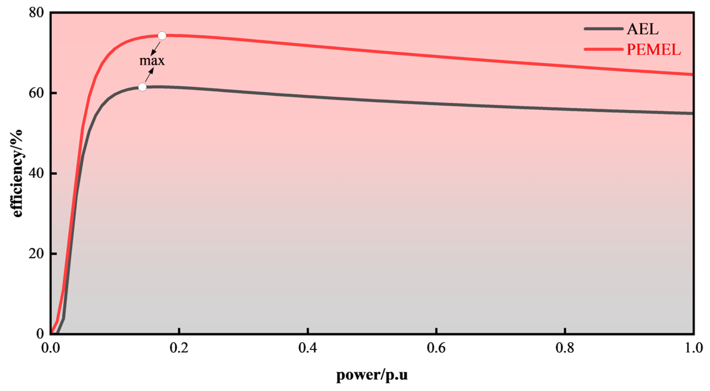
2.3. Hydrogen Production Efficiency Model
3. Multi-Mode Electrolyzer Cluster Control Optimization
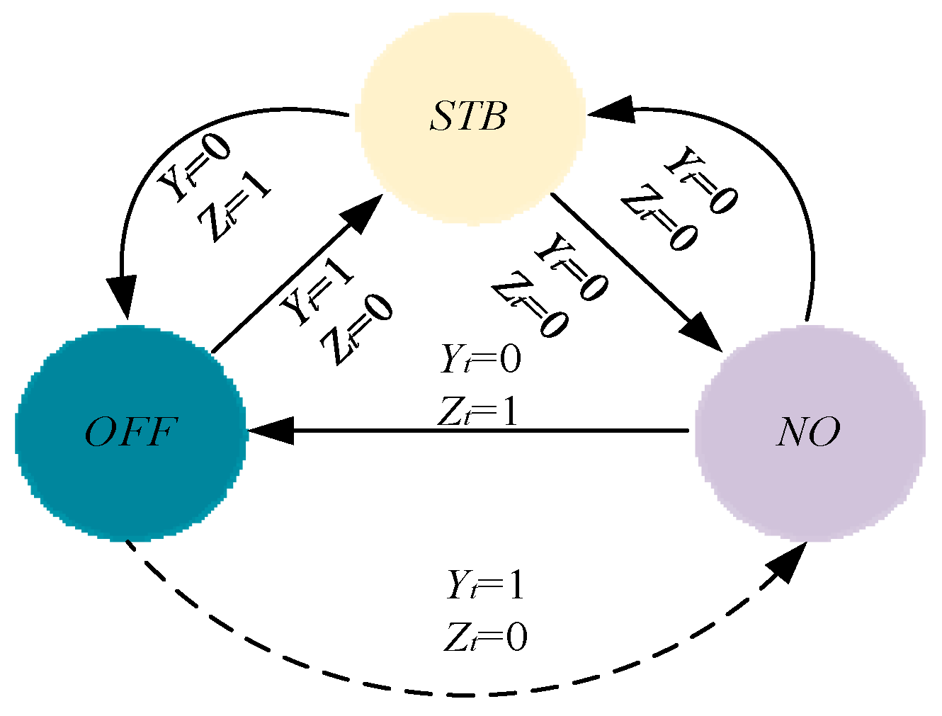
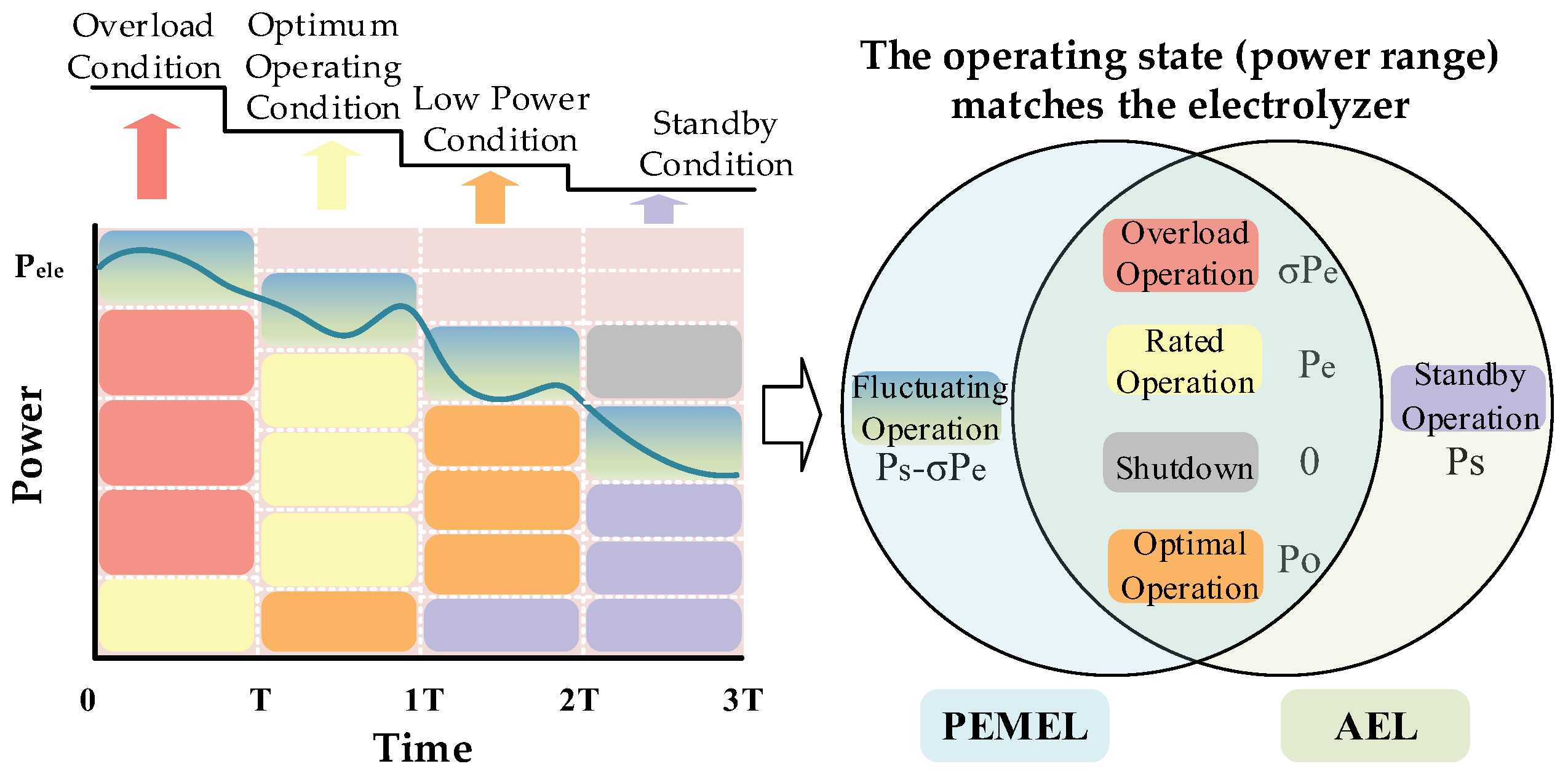
3.1. Electrolyzer Operating State Division Under Complex Operating Conditions
3.2. Design of Power Matching Mechanism for Electrolyzer Cluster
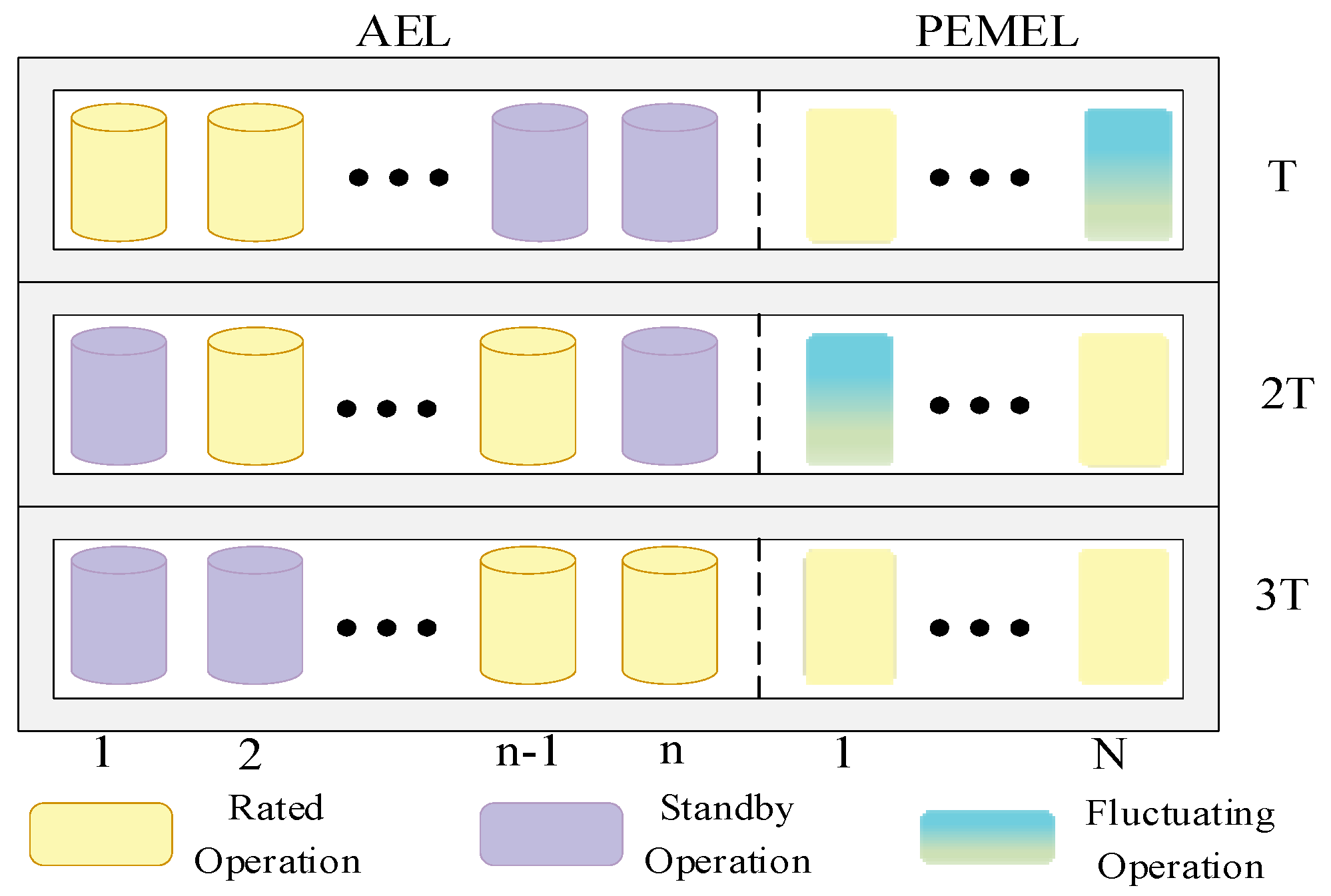
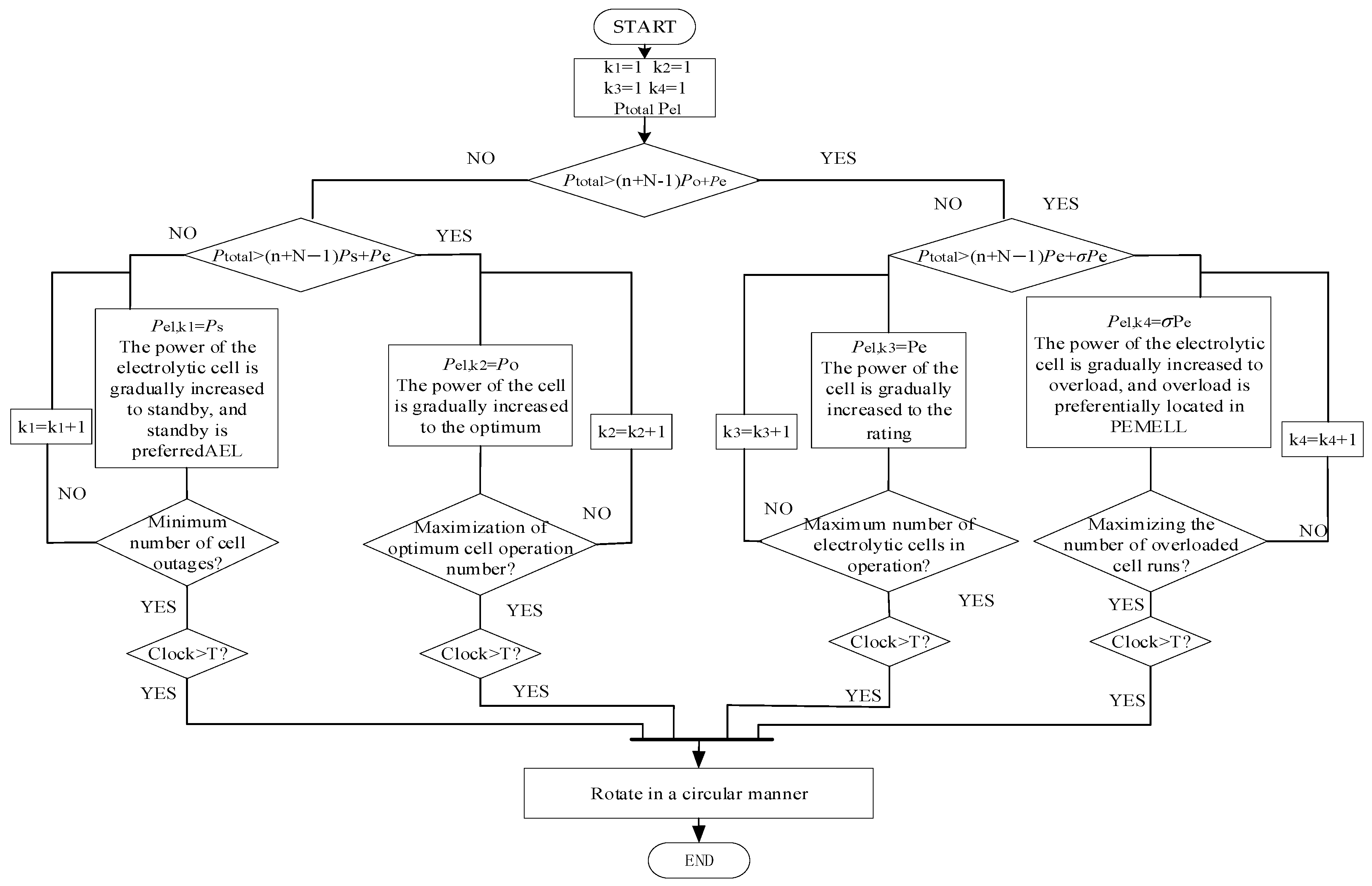
3.3. Optimization of Rotational Control Strategy for Composite Electrolyzer Cluster
3.3.1. Overload Condition
3.3.2. Optimum Operating Condition
3.3.3. Low-Power Condition
3.3.4. Standby Condition
4. Simulation Verification
4.1. Stability of Electrolyzer Cluster
- (1)
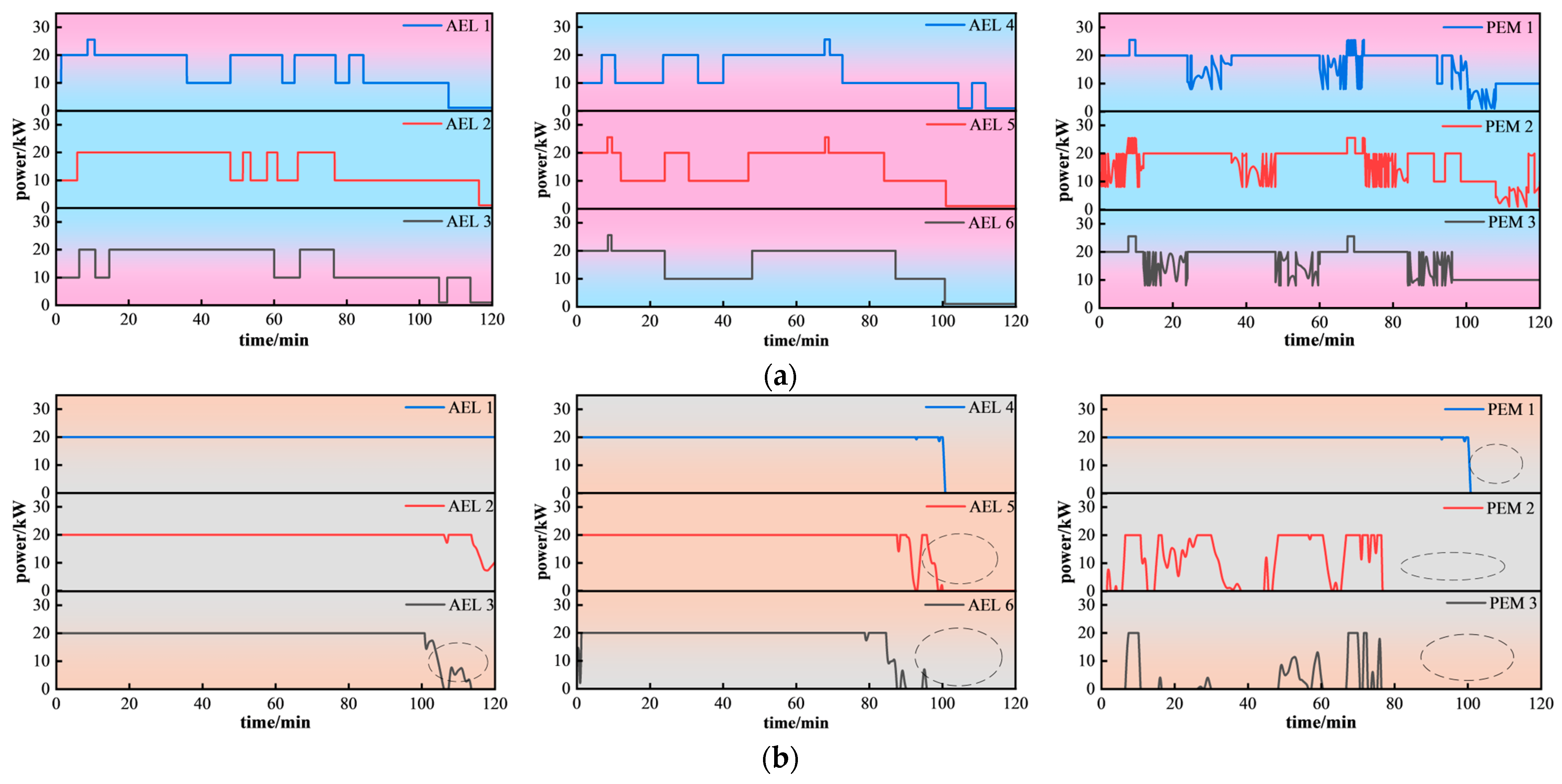
- The control strategy proposed for this paper prevented the AEL from entering fluctuating and downtime states, with the PEM electrolyzer handling the majority of the fluctuating power, accounting for over 33%. This ensured that the system not only reduced frequent start–stop situations but also fully utilized the strong capability of PEMEL to adapt to fluctuating power sources.
- (2)
- The rated operating time of AELs ranges from 42.76% to 51.71%, while that of PEMELs is mostly between 46.85% and 51.43%. This indicates that the system operated at rated power for the majority of the time, ensuring safe and efficient hydrogen production.
- (3)
- Compared to PEMELs, AELs exhibit relatively longer optimal operating durations, accounting for 33.15% to 49.25% of the total time. This suggests that AELs operate in their optimal state more frequently, effectively enhancing hydrogen production efficiency.
- (4)
- The introduction of a standby state reduces the probability of electrolyzer shutdowns and ensures the continuity of system operation.
4.2. Dynamic Real-Time Response Performance Analysis of Electrolyzers
4.3. Effectiveness of Optimized Control Strategies for Electrolyzer Clusters
5. Conclusions
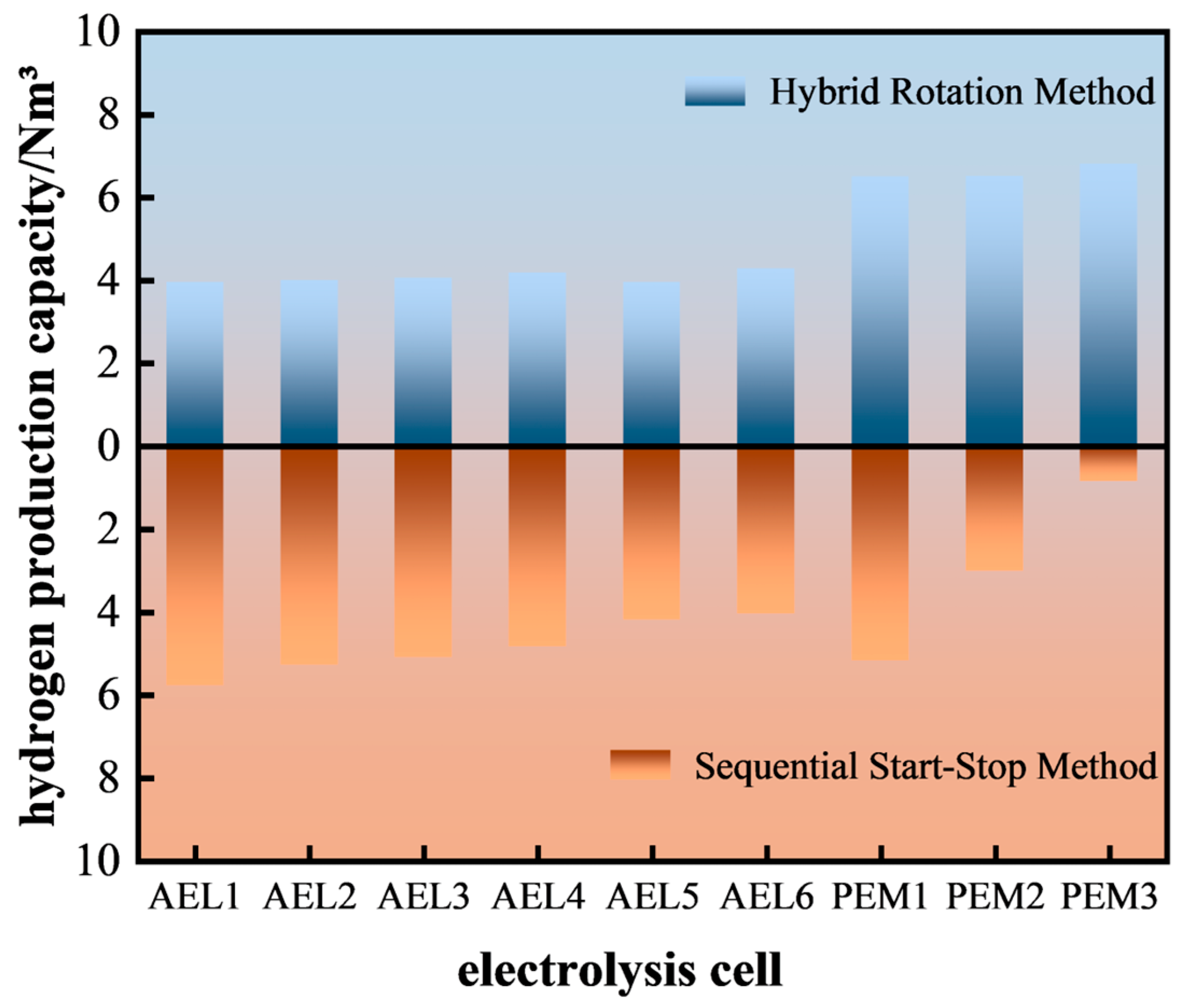
- (1)
- Under the same wind and solar power output conditions, the differentiated utilization of the operational response characteristics of AEL and PEMEL helps improve the operational efficiency and stability of the electrolysis hydrogen production system. Compared with the traditional sequential start–stop method, the proposed strategy increases the overall hydrogen production by 10.73%, and the hydrogen production from both electrolyzer types shows significant uniformity.
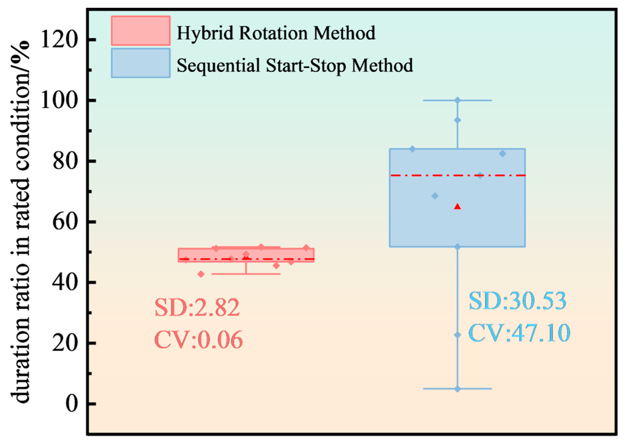
- (2)
- Compared with the traditional sequential start–stop method, the proposed strategy reduces the standard deviation and coefficient of variation in the system’s rated operation duration by 27.71 min and 47.04, respectively. This balances the operational duration of individual electrolyzers in the rated state, indirectly extending the working life of the electrolyzer cluster.
Author Contributions
Funding
Data Availability Statement
Conflicts of Interest
Appendix A

| Parameter | Value | Parameter | Value |
|---|---|---|---|
| Isc | 2.69 A | Uoc | 7.2 V |
| Um | 6.0 V | Im | 2.5 A |
| β | 0° | ρ | 1.29 kg/m3 |
| T | 298 K | nω | 100 r/min |
| 1 | R | 8.3144 J·mol−1K−1 | |
| αan | 0.8 | F | 96,485 C·mol−1 |
| αcat | 0.25 | A | 160 cm2 |
| io,cat | 1 × 10⁻¹ A/cm2 | λ | 21 |
| io,an | 1 × 10⁻⁷ A/cm2 | δmem | 0.0254 cm |
| ρeff | 18.1 × 10⁻⁶ Ωcm | δel | 0.008 cm |
| ε | 0.3 | r1 | 8.232 × 10⁻⁵ Ωcm2 |
| ξ | 4 | r2 | −4.51 × 10⁻⁷ Ωcm2 |
| 59.7 K | z | 2 | |
| 106.7 K | εH2O | 809.1 K |
References
- Moghaddam, A.L.; Hejazi, S.; Fattahi, M.; Kibria, M.G.; Thomson, M.J.; AlEisa, R.; Khan, M.A. Methane Pyrolysis for Hydrogen Production: Navigating the Path to a Net Zero Future. Energy Environ. Sci. 2025, 18, 2747–2790. [Google Scholar] [CrossRef]
- Guo, Y.; Li, G.; Zhou, J.; Liu, Y. Comparison Between Hydrogen Production by Alkaline Water Electrolysis and Hydrogen Production by PEM Electrolysis. IOP Conf. Ser. Earth Environ. Sci. 2019, 371, 042022. [Google Scholar] [CrossRef]
- Huang, Q.F.; Chen, J.; Cao, X.M.; Liu, J.; Zhang, Y.; Bao, Y. Optimization of wind-photovoltaic complementation hydrogen production system based on synergistic hydrogen production by alkaline electrolyzer and proton exchange membrane electrolyzer. Electr. Power Autom. Equip. 2023, 43, 168–174. [Google Scholar]
- Zheng, B.; Bai, Z.; Yuan, Y.; Hu, X. Hydrogen production system and capacity optimization based on synergistic operation with multi-type electrolyzers under wind-solar power. Proc. CSEE 2022, 42, 8486–8496. [Google Scholar]
- Jiang, Y.W.; Yang, G.M.; Chen, Y.X.; Huang, W. Optimal operation for the hydrogen network under consideration of the dynamic hydrogen production efficiency of electrolyzers. Proc. CSEE 2023, 43, 3014–3027. [Google Scholar]
- Yuan, T.J.; Wan, Z.; Wang, J.J.; Zhang, D.; Jiang, D. The day-ahead output plan of hydrogen production system considering the startstop characteristics of electrolytic cell. Electr. Power 2022, 55, 101–109. [Google Scholar]
- Shen, X.J.; Nie, C.Y.; Lv, H. Coordination control strategy of wind power-hydrogen alkaline electrolyzerbank considering electrothermal characteristics. Trans. China Electrotech. Soc. 2021, 36, 463–472. [Google Scholar]
- Niu, M.; Hong, Z.P.; Li, B.; Li, X. Optimal control strategy of wind power to hydrogen system considering electrolyzer efficiency improvement. Acta Energiae Solaris Sin. 2023, 44, 366–376. [Google Scholar]
- Chen, M.P.; Ren, J.X.; Li, F.Q. Coordinated and stable operation of wind solar complementarity and load of electrolytic water hydrogen production system. Acta Energiae Solaris Sin. 2023, 44, 344–350. [Google Scholar]
- Cao, X.; Wang, J.; Zhao, P.; Xia, H.; Li, Y.; Sun, L.; He, W. Hydrogen production system using alkaline water electrolysis adapting to fast fluctuating photovoltaic power. Energies 2023, 16, 3308. [Google Scholar] [CrossRef]
- Abdin, Z.; Webb, C.J.; Gray, E.M.A. Modelling and simulation of a proton exchange membrane (PEM) electrolyser cell. Int. J. Hydrogen Energy 2015, 40, 13243–13257. [Google Scholar] [CrossRef]
- Abdin, Z.; Webb, C.J.; Gray, E.M.A. Modelling and simulation of an alkaline electrolyser cell. Energy 2017, 138, 316–331. [Google Scholar] [CrossRef]
- Yang, J.; Zhang, J.; Liu, M.; Sun, J.; Shangguan, Z. Dynamic simulation and performance analysis of alkaline water electrolyzers for renewable energy-powered hydrogen production. Energies 2024, 17, 4915. [Google Scholar] [CrossRef]
- Wei, F.R.; Sui, Q.; Lin, X.N.; Li, Z.; Chen, L.; Zhao, B.; Xu, C.; Adio, O.S. Scheduling optimization strategy of coal-air hydrogen energy network considering efficiency characteristics of hydrogen production equipment. Proc. CSEE 2018, 38, 1428–1439. [Google Scholar]
- Fang, R.; Liang, Y. Control strategy of electrolyzer in a wind-hydrogen system considering the constraints of switching times. Int. J. Hydrogen Energy 2019, 44, 25104–25111. [Google Scholar] [CrossRef]
- Shen, X.; Zhang, X.; Li, G.; Lie, T.T.; Hong, L. Experimental study on the external electrical thermal and dynamic power characteristics of alkaline water electrolyzer. Int. J. Energy Res. 2018, 42, 3244–3257. [Google Scholar] [CrossRef]
- Varela, C.; Mostafa, M.; Zondervan, E. Modeling alkaline water electrolysis for power-to-x applications: A scheduling approach. Int. J. Hydrogen Energy 2021, 46, 9303–9313. [Google Scholar] [CrossRef]
- Matute, G.; Yusta, J.M.; Correas, L.C. Techno-economic modelling of water electrolysers in the range of several MW to provide grid services while generating hydrogen for different applications: A case study in Spain applied to mobility with FCEVS. Int. J. Hydrogen Energy 2019, 44, 17431–17442. [Google Scholar] [CrossRef]
- Chen, Z.X.; Zhang, Y.C.; Zhu, S.; Xie, S. Optimal scheduling electricity-hydrogen-heat integrated energy system considering combined operation of multi-electrolyzers under multiple conditions. Power Syst. Technol. 2025, 49, 542–551. [Google Scholar]
- Li, J.L.; Liang, Z.H.; Zhao, W.D.; Li, G.; Li, M. Selection and evaluation method of hydrogen production system in hybrid electrolytic cell. High Volt. Eng. 2024, 50, 2653–2662. [Google Scholar]


| Operation Mode | Fluctuating | Overload | Rated | Optimal | Standby | Shutdown |
|---|---|---|---|---|---|---|
| AEL 1 | 0 | 0 | 49.30 | 43.85 | 6.85 | 0 |
| AEL 2 | 0 | 0 | 47.72 | 49.25 | 3.03 | 0 |
| AEL 3 | 0 | 1.66 | 51.71 | 36.63 | 10.00 | 0 |
| AEL 4 | 0 | 1.41 | 51.18 | 33.15 | 14.26 | 0 |
| AEL 5 | 0 | 1.86 | 45.59 | 37.60 | 14.94 | 0 |
| AEL 6 | 0 | 1.20 | 42.76 | 45.79 | 10.05 | 0 |
| PEMEL 1 | 33.00 | 3.23 | 48.85 | 19.91 | 0 | 0 |
| PEMEL 2 | 34.00 | 3.04 | 47.5 | 15.46 | 0 | 0 |
| PEMEL 3 | 33.00 | 2.42 | 51.43 | 18.15 | 0 | 0 |
Disclaimer/Publisher’s Note: The statements, opinions and data contained in all publications are solely those of the individual author(s) and contributor(s) and not of MDPI and/or the editor(s). MDPI and/or the editor(s) disclaim responsibility for any injury to people or property resulting from any ideas, methods, instructions or products referred to in the content. |
© 2025 by the authors. Licensee MDPI, Basel, Switzerland. This article is an open access article distributed under the terms and conditions of the Creative Commons Attribution (CC BY) license (https://creativecommons.org/licenses/by/4.0/).
Share and Cite
Tan, Q.; Li, K.; Zeng, L.; Xie, L.; Cheng, M.; He, W. A Multi-State Rotational Control Strategy for Hydrogen Production Systems Based on Hybrid Electrolyzers. Energies 2025, 18, 2008. https://doi.org/10.3390/en18082008
Tan Q, Li K, Zeng L, Xie L, Cheng M, He W. A Multi-State Rotational Control Strategy for Hydrogen Production Systems Based on Hybrid Electrolyzers. Energies. 2025; 18(8):2008. https://doi.org/10.3390/en18082008
Chicago/Turabian StyleTan, Qingshan, Ke Li, Longquan Zeng, Lu Xie, Man Cheng, and Wei He. 2025. "A Multi-State Rotational Control Strategy for Hydrogen Production Systems Based on Hybrid Electrolyzers" Energies 18, no. 8: 2008. https://doi.org/10.3390/en18082008
APA StyleTan, Q., Li, K., Zeng, L., Xie, L., Cheng, M., & He, W. (2025). A Multi-State Rotational Control Strategy for Hydrogen Production Systems Based on Hybrid Electrolyzers. Energies, 18(8), 2008. https://doi.org/10.3390/en18082008