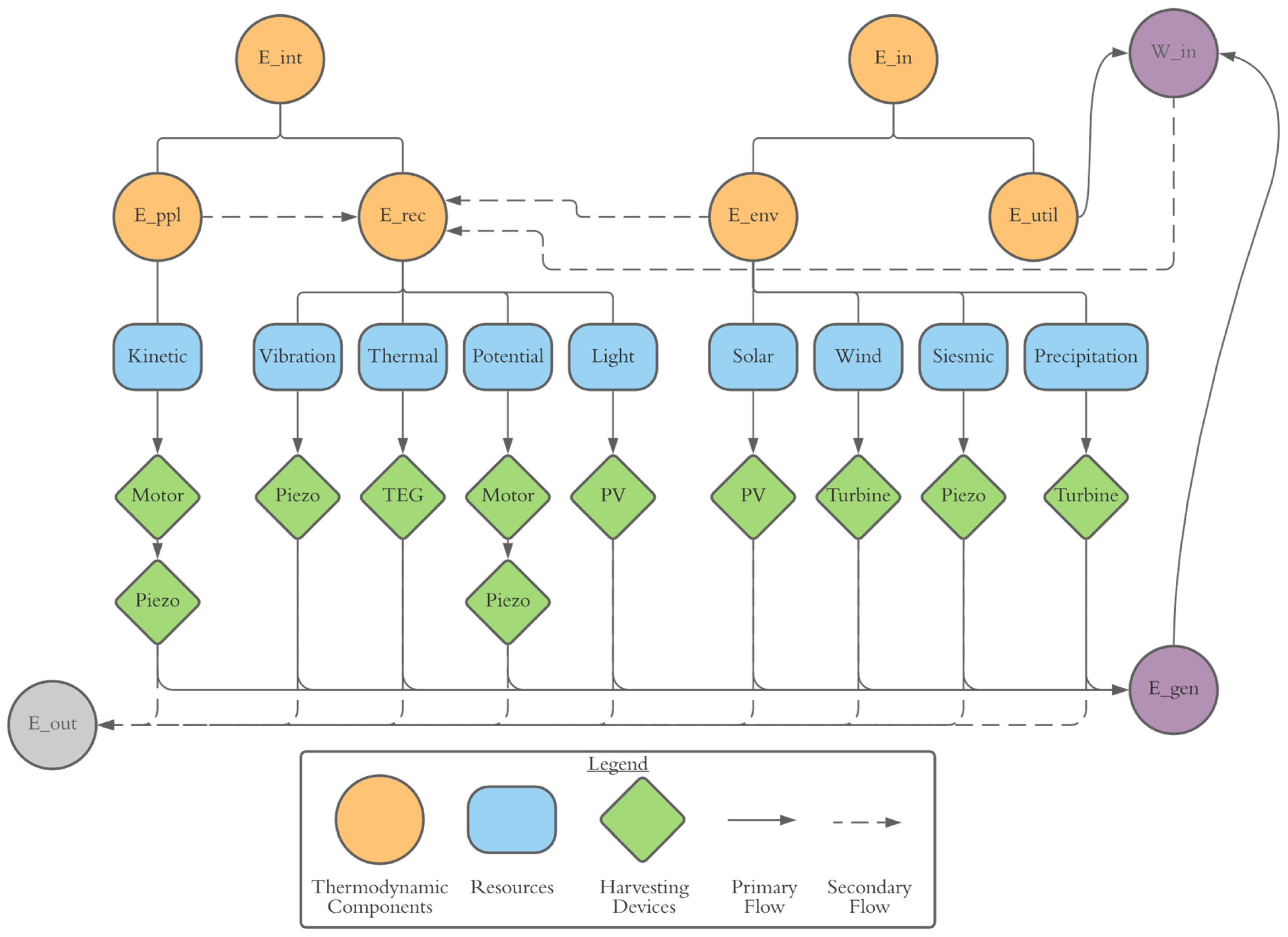
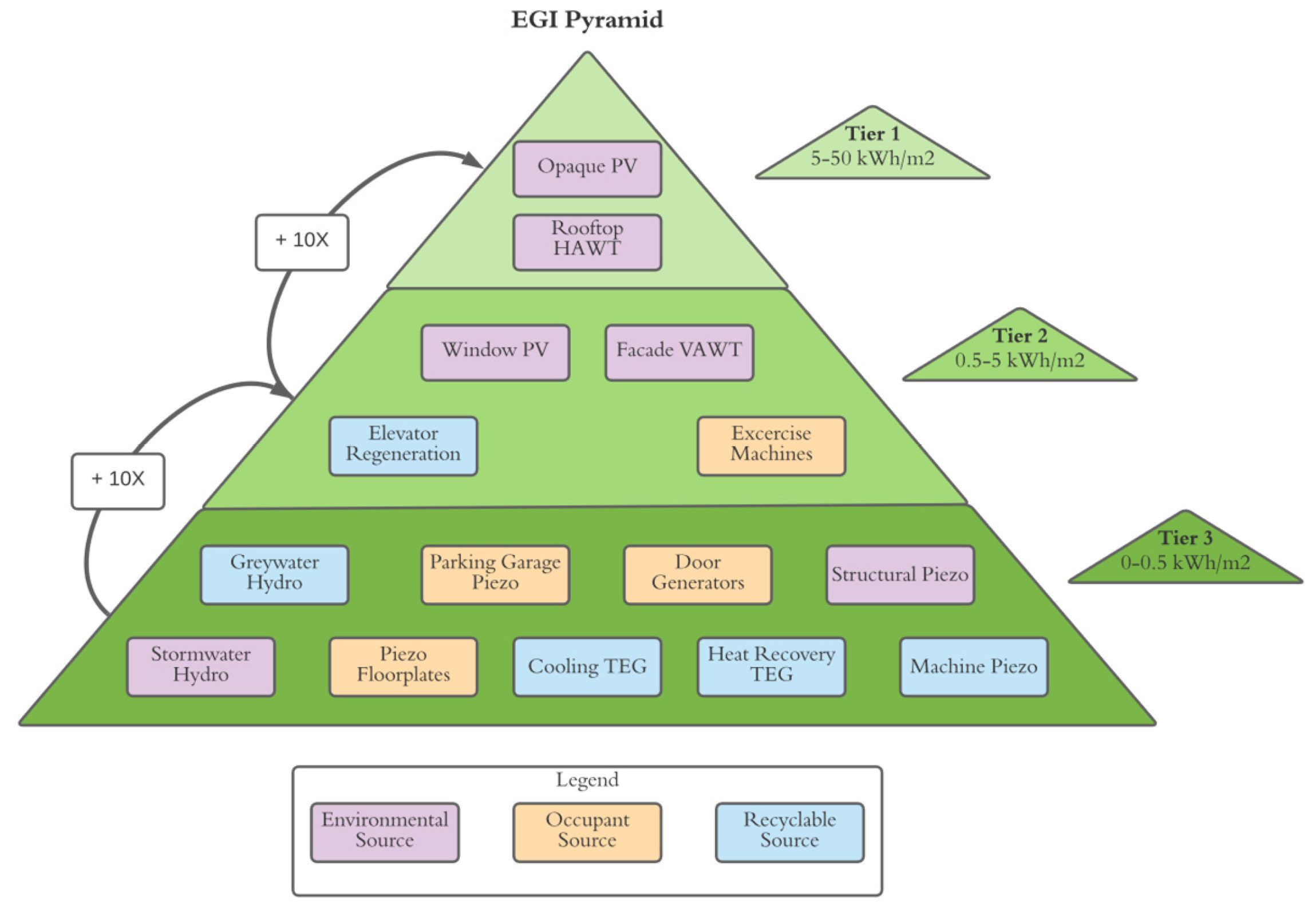
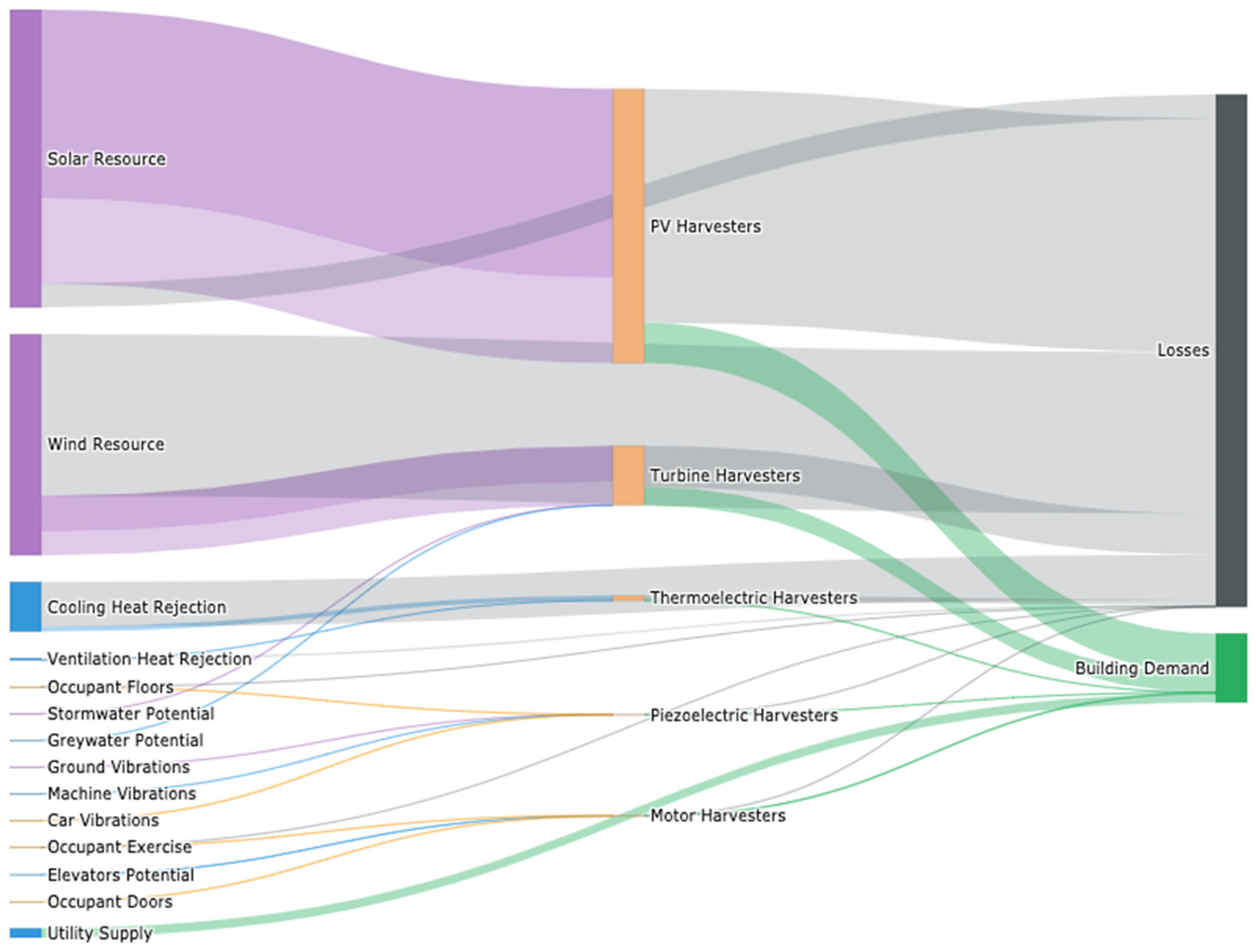
The following sections will describe the state-of-the-art technologies available today for converting the energy resources described into the electrical domain.
3.1. Photovoltaics
The photovoltaic effect is a property of semiconductor materials and alloys which enables the production of electric current in response to absorption of light. This process relates to the bonding energy of the valence electrons in the given material, described as the band-gap energy. As photons are absorbed by the material with energy greater than the band gap, electrons are displaced from the valence band of the material into the conduction band. Photovoltaic cells employ doped materials in a p-n junction to enable the efficient collection of the displaced electrons to provide current to an external circuit.
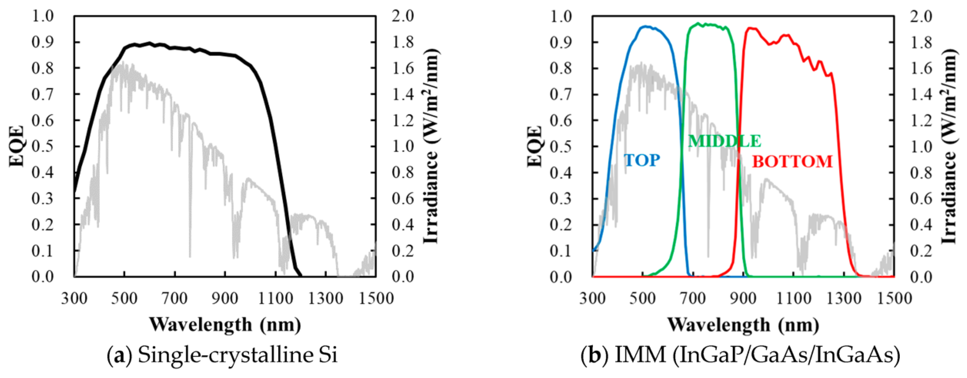
Due to the nature of this effect, the total conversion efficiency is a function of a given material’s band-gap energy. When a photon with energy below the band gap is absorbed, no current can be produced, while a photon with energy greater than the band gap produces a current but loses its excess energy to heat. The net response of a material at this level can be quantified by the quantum efficiency (QE), which is a function of photon wavelength. Mass-market photovoltaic devices are typically composed of single-junction silicon cells which provide a relatively broad match to the terrestrial solar radiation spectrum, resulting in module-level efficiencies around 20%. One of the key areas of interest in photovoltaic development is the production of tandem junction cells, which utilize multiple layers of semiconductors with complimentary band gaps, such that a broader range of the incoming solar spectrum can be more efficiently collected. This concept in depicted in
Figure 7 [
40].
The external quantum efficiency (EQE) describes the ratio of electrons excited to photons absorbed over the range of available solar spectra. However, EQE does not account for the thermal losses resulting from photon energies above the band gap. The ultimate limit to efficiency with this relation considered has been presented in the Shockley–Queisser limit [
41], which defines the maximum achievable conversion efficiency for a single junction solar cell, shown to maximize around 33.8% [
42]. Following Shockley’s approach, the theoretical efficiency limitation for an infinite junction tandem cell has been subsequently defined by Vos as 68.2% [
43]. Alharbi and Kais [
44] provide a thorough review of the prospects in approaching these theoretical limits with feasible technologies.
PV efficiency limits are generally defined at standard test conditions (STCs) involving AM1.5 irradiance spectrum and 25 °C. In practice, cell efficiency is further limited by actual operating temperature, incident irradiance spectra, and manufacturing limitations, among other factors.
Theoretical efficiency can be increased by enhancing the intensity of the incident radiation, as is the approach taken by concentrated PV (CPV) cells. High levels of concentration have been shown by Vos to increase the theoretical efficiency above 40% for single junction cells; however, this technology has generally not proven successful in practice due to thermal issues which reduce the practical efficiency and risk cell damage. CPV also lacks effectiveness with diffuse and reflected radiation, which can represent a significant portion of the available resource in cloudy climates.
Additional approaches exist in practice that enable the enhanced utilization of a given surface for light collection. With these methods, efficiency is not improved, but net output gains per unit surface area are achieved by increasing total access to light. Noteworthy technologies include single- and double-axis tracking systems which control the orientation of collection surfaces throughout the day to minimize the AOI, resulting in an achievable additional production of 25% and 45%, respectively, dependent on location [
45]. Alternatively, bifacial cells, which are rapidly gaining industry adoption, enable light collection on both the front and back side of a cell, enabling the collection of reflected, diffuse, and artificial light that may be present on the side of the cell which faces away from direct radiation. This technology has been shown to enable annual energy gains on the order of 25% in traditional array geometries [
46].
When considering building integrated application for photovoltaics, the most common application is to mount traditional PV panels in a fixed-tilt orientation on a roof. However, innovative products are in development that integrate photovoltaic technology into traditional cladding systems. This concept of cladding-integrated PV trends towards enabling combined BIPV/T systems, which harvest waste heat from PV collectors to serve a building’s thermal demand [
47]. In addition, a few advanced technologies exist for integrating PV properties into glass, to enable energy production without compromising visible transmittance. Of course, these applications are limited in the achievable efficiency given their transparent nature, with published results in the range of 3.6% [
48].
3.2. Turbines
Wind-harvesting turbines can be generally categorized into two main types: horizontal axis (HAWT) and vertical axis (VAWT). Horizontal-axis machines comprise the bulk of utility-scale wind farms due to their relatively high efficiency [
49]. The blades of a HAWT rotate in a vertical plane and thus must be controlled, either actively or passively, to point into the wind stream in order to extract maximum power.
Vertical-axis turbines utilize blades which rotate in the horizontal plane. Because of this feature, VAWTs can extract power from all wind directions without orientation control, lending to suitability in locations with a high degree of variability in the wind resource. There are two main types of VAWTs; Savonius and Darrieus, which operate on drag and lift forces, respectively [
50]. Darrieus, or lift-based VAWTs, generally have a higher achievable efficiency; however, they are unable to self-start due to their symmetry, thus requiring input energy to initiate rotation. Savonius, or drag-based VAWTs, are self-starting and require the least amount of control, yet exhibit the lowest efficiency of the surveyed machines [
51]. Combined VAWT designs are commonly deployed such that the Savonius component provides the self-starting torque and the Darrieus component enables higher efficiency operation at higher wind speeds. Each design may also be modified with a helical twist along its axis, which acts to reduce backside drag in an effort to increase the achievable power coefficient (Cp). The various models are depicted in
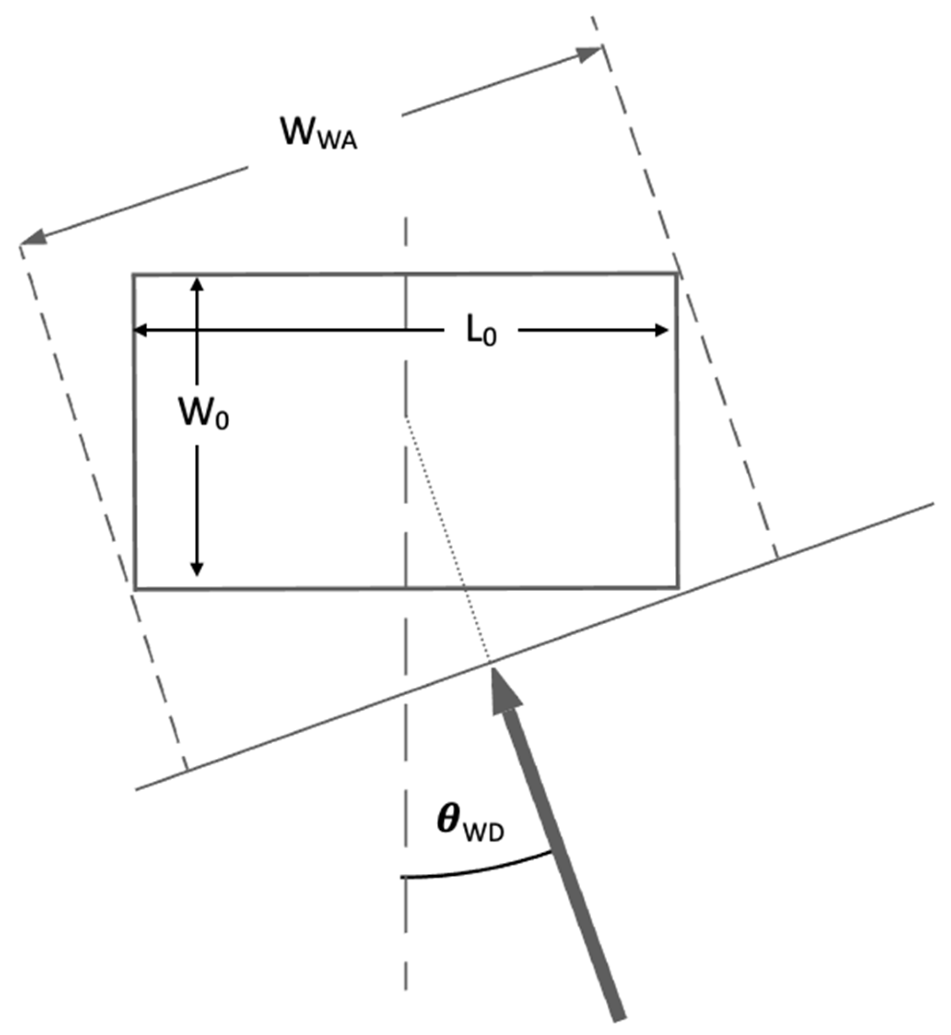
Figure 8 [
52].
A noteworthy difference between drag- and lift-type turbines is their effective tip-speed ratio, and resultant machine RPMs. Drag-based turbines are limited to a tip-speed ratio of 1 and thus generally require gearboxes to amplify the rotational velocity to a compatible rate with the generator being utilized. For lift-based turbines, higher tip-speed ratios can be achieved [
53], which may enable direct motor-drive applications. The addition of a gearing system to the power train will generally introduce losses on the order of 5%, which may be worthwhile, though dependent on the base turbine rotational dynamics. Motor generator typologies will be briefly discussed in
Section 3.5. In an effort to harvest consistently, low-wind-speed crossflow VAWT designs have been suggested [
54] and shown to exhibit the highest achievable power coefficient of existing turbines at tip-speed ratios below 0.5. The performance benefit of this typology, however, has not been proven in practice [
55].
Available wind power can be derived from a laminar flow in accordance with Equation (24), which builds on Equation (9), with the addition of area, power coefficient, and efficiency terms,
where
P is the available electrical power,
A is the effective area of the turbine,
Cp is the power coefficient of the turbine, and
ηelec is the generator electrical efficiency. When applications necessitate a mechanical gearbox, an additional term may be added to account for the corresponding losses.
Wind-turbine power coefficients vary with wind speed, typically maximized at rated wind speed and decreasing at higher speeds due to stability limitations. The maximum
Cp that can be achieved in a wind turbine is ultimately limited by Betz law, which applies to fluid flow in an open system, and works out to 16/27 or 59.3% of the total available energy [
56]. This limitation follows from the notion that 100% efficiency would necessitate downstream air molecules to be motionless, meaning additional molecules would be prevented from flowing through the turbine, and would flow around it instead. Common
Cps for the turbine types described are presented in
Table 3.
Given the capacity of building geometry to affect wind velocity as described in
Section 2.2, many researchers have proposed building-integrated wind-turbine designs which leverage building geometry to accelerate flows strategically across a turbine to increase yield. This concept of building-integrated wind is well demonstrated in [
57,
58], where wind turbines are positioned horizontally between neighbouring towers as well as vertically between stories of a given building. Both authors note the importance of optimal building geometry in order to maximize the effective acting velocity ratio to accelerate incoming flows. Hassanli et al. [
59] proposed a double-skin façade system designed for the purposes of wind-energy harvesting, ultimately noting that turbulence is reduced inside the façade cavity and average speed is increased.
Recently, interest has developed towards resonant wind-harvesting devices, described as bladeless turbines. These machines employ vertical members hinged near the base to enable single-degree-of-freedom oscillations induced via vortex shedding. The resultant oscillations may be converted into electricity via piezoelectric materials or coupling with a permanent magnet alternator, as proposed by Villarreal [
60].
In hydro applications, flows are contained closed systems where Betz law does not apply, so higher Cps can be achieved. Jawahar and Michael [
61] present efficiencies ranging from 60 to 91% for turbines relevant to micro-hydro application. Santillan concludes that the Pelton type, which operates at low speeds and high pressure, is the most appropriate selection for building application. Crossflow turbines may also be well suited to certain buildings depending on the characteristics of the given resource. Binama et al. [
62] note the potential benefits of simple pump geometries deployed as turbines, which are shown to achieve efficiencies up to 80% in a well-tuned system with dramatically lower capital cost than their more sophisticated counterparts.
3.3. Piezoelectric Materials
The piezoelectric effect is the accumulation of electric charge in a material in response to mechanical stress. Piezoelectric materials are inherently dielectric and anisotropic with asymmetric dipole distributions in their crystal lattice. These properties lend to electric polarization in response to distortion in the crystal lattice of a material from an applied stress. This dynamic is described by the electro-mechanical coupling equations, presented in Equations (25) and (26), which relate the mechanical and dielectric responses of a material via the piezoelectric effect;
where
σ is the mechanical stress,
s is the material compliance, which relates to the inverse of the elastic modulus,
X is the strain,
d is the piezoelectric constant,
E is the applied electric-field vector,
ε is the dielectric permittivity, and
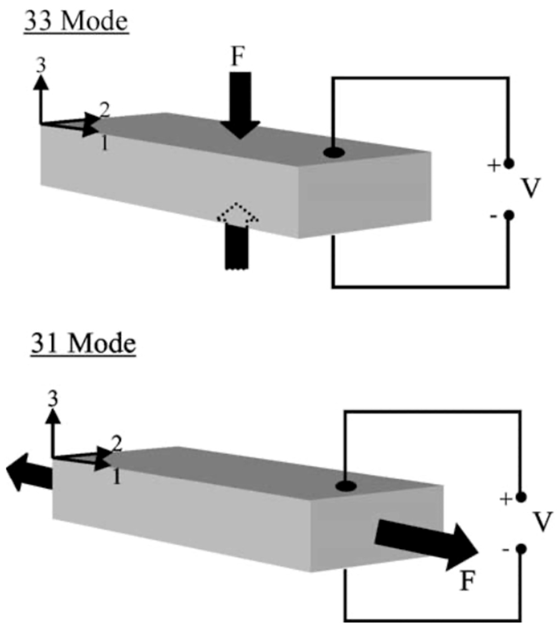
D is the electric displacement or resultant charge density. In a given material, the coupling has three distinct modes, in reference to the axes of induced strain and electric displacement in relation to the principal axis of the crystal lattice. This concept is depicted in
Figure 9 from Roundy et al. [
18].
The magnitude of energy transduction between mechanical and electrical forms in a piezoelectric material depends on the material’s coupling coefficient; k
2 is defined generally as the ratio of electrical energy stored in the material to mechanical energy input. The coupling coefficient can be related to the basic physical properties of the material in accordance with Equation (27),
where
δ is the Young’s modulus or stiffness of the material. Ultimately, the amount of energy that can be harvested from a piezoelectric transducer is a function of the transmission coefficient, λ. While the coupling coefficient is a property of a piezoelectric material, the transmission coefficient factors in the compatibility of mechanical and electrical loading conditions to enable effective energy transfer. Through first-principles derivation, Roundy has shown that the maximum achievable transmission coefficient relates directly to the coupling coefficient per Equation (28),
which is relatively consistent with the limitations provided by Uchino [
63], in Equation (29),
For energy transmission to be maximized, a piezoelectric energy-harvesting system must be designed such that its resonant frequency matches the dominant excitation frequency [
64]. There is some flexibility with this, as the resonant frequency of the device will depend on the load resistance, which may be tuned to some extent with maximum power point tracking and alternative electrical integrations, such as that described by Liang and Liao [
65]. Shafer and Garcia [
66] have shown that for a piezoelectric harvesting device operating in resonant conditions, the maximum achievable efficiency increases with the ratio of the coupling coefficient to the mechanical damping ratio and reaches an upper limit at about 44%. In structurally integrated applications, a significant portion of the internal stress must be borne by piezoelectric elements rather than the base structural material for this efficiency limit to be upheld. For an accurate estimation of energy-generation potential, finite-element models could be employed as a design tool to relate internal stress to piezoelectric generating potential under complex three-dimensional loading and geometries.
Covaci and Gontean [
60] note that a high degree of system coupling can be elusive at low vibration frequencies due to the difficulty of enabling low resonant frequencies in a harvesting device. Generally piezoelectric ceramics have higher resonant frequencies, while piezoelectric polymers can achieve lower frequencies. This would indicate that polymer materials are better suited to building applications, given the lower frequency vibrations that are generally present [
16,
18].
In a building, numerous applications can be theorized for piezoelectric energy harvesting. Many researchers have explored the alluring opportunity of integrating piezoelectric materials into building structures. As described by Chen et al. [
67], compatibility between cement and piezoelectric treatments has been demonstrated. Chen at al. summarize several treatment methods and additives explored in the literature to create a piezoelectric effect in concrete mixtures. A common method of applying piezoelectric materials for vibration damping is the shunt-damping approach, which is described by Moheimani and Fleming [
68] as the structural bonding of a piezoelectric transducer to a flexible material with external electrical impedance or load. This represents a promising approach for integration into non-concrete building structures which align well with the impactful industry goals of reduction in lifecycle carbon.
At the microscale, the bimorph architecture is a common device typology where piezoelectric materials are applied to either side of a cantilevered beam under vibration. Recent work most commonly focuses on bimorph harvesters applied to base vibrations with a small proof mass to excite the bimorph at its natural frequency [
69,
70]. However, the bimorph architecture can also be applied in shunt-damping applications. A detailed electrical–mechanical model for a bimorph shunt damper is presented by Liao and Sodano [
71] to inform the optimal placement of piezoelectric patches and the resultant dynamic response of cantilevered beams.
In the context of piezoelectric roadways which can be applied in building parking garages and neighbouring parking lots, Wang et al. [
72] report an annual energy output of 188 kWh/lane/mile, in accordance with the model results presented by Zhang et al. [
73]. Zhang’s results have shown that the instantaneous power output from a single piezoelectric transducer embedded in a roadway is proportional to vehicle velocity, with a reported output of 47 mW under a four-wheel load at 30 m/s. Guo and Lu [
74] contrarily report results from the literature as well as their own analysis, which indicate outputs of 200 and 300 mW under a vehicle speed of 8 km/h and excitation frequencies of 30 Hz, respectively. The authors [
74] speculate that these could be improved with reduced pavement stiffness lending to improve electromechanical coupling.
3.4. Thermoelectric Generators
Thermoelectric generators (TEGs) are solid-state, semi-conductor devices which produce electric current in response to directional thermal gradients, in accordance with the Seebeck effect. TEGs have garnered interest in applications ranging across industrial waste heat, automobile exhaust, body-heat scavenging, and deep-space exploration [
75,
76].
A thermoelectric device is typically composed of an array of thermocouples connected electrically in series and thermally in parallel. These devices are also commonly employed in industrial electronics for their cooling capability when operated in a reverse, according to the Peltier effect [
77,
78]. In both applications, thermoelectric devices are of interest given their simplicity and lack of moving parts.
Generally thermoelectric generators exhibit limited conversion efficiency [
79], but have been shown to have the capacity for significant power generation, provided a high-grade thermal resource [
80]. When considering opportunities for thermoelectric harvesting in buildings, a balance must be struck between tapping significant resources, and avoiding upstream inefficiencies.
The performance of TEGs may be classified in accordance with the thermoelectric figure of merit (ZT), described by Equation (30),
where
α is the Seebeck coefficient,
ρ is the electrical resistivity,
λ is the thermal conductivity and
T is the average temperature of the device. In practice, the figure of merit varies with temperature, and certain materials are best suited to certain temperature ranges. A detailed figure of the merit derivations with the temperature dependencies considered is presented by Hapenciuc et al. [
81] and Kim et al. [
82]. In the context of buildings, thermal gradients are generally modest, with average temperatures in the range of 300 K. These conditions are suitable for Bismuth Telluride-based TEGs, which are one of the most common thermoelectric materials on the market today [
83,
84]. As a form of heat engine, the maximum theoretical efficiency of a TEG is limited by the Carnot limit. In practice, this maximum efficiency is further limited by the device ZT, in accordance with Equation (31),
Many commercially available thermoelectric materials exhibit ZT in the range of 1, with a ZT of 2 being considered a standard of high performance [
85]. Zhao et al. [
86] achieved a record ZT of 2.6 at 923 K via the implementation of monocrystalline SnSe with manufacturing approaches lending to extremely low thermal resistance [
87].
As illustrated well by Hapenciuc et al. [
81], the total heat flow across a TEG comprises three components, corresponding to Fourier heat, Peltier heat, and Joule heating. The total heat input can thus be described as below in Equation (32),
where
Qh is the total heat flow,
A is the cross-sectional area normal to heat flow,
L is the thickness of the material parallel with heat flow,
I is the current flowing through the device and
r is the total electrical resistance of device. Equations (30)–(32) can be considered in the context of a full TEG device assembly, consistent with the methods presented in [
88], which allows for an analysis on a per unit area of implementation basis. Thus, the potential power density for a given application can be evaluated according to Equation (33),
where
P is the power per unit area,
Qhm is the heat flow across the module, and
Ad represents the area of the module, which factors in the packing density of thermocouples in the device. When evaluating the temperature delta of a given application, it is critical that the effective thermal resistance of contact and surface films be factored in accordance with
Figure 10. Simply taking the delta between two fluid temperatures on either side of a TEG device will yield substantial overestimates in power output, as the temperatures at the actual material interfaces are misrepresented.
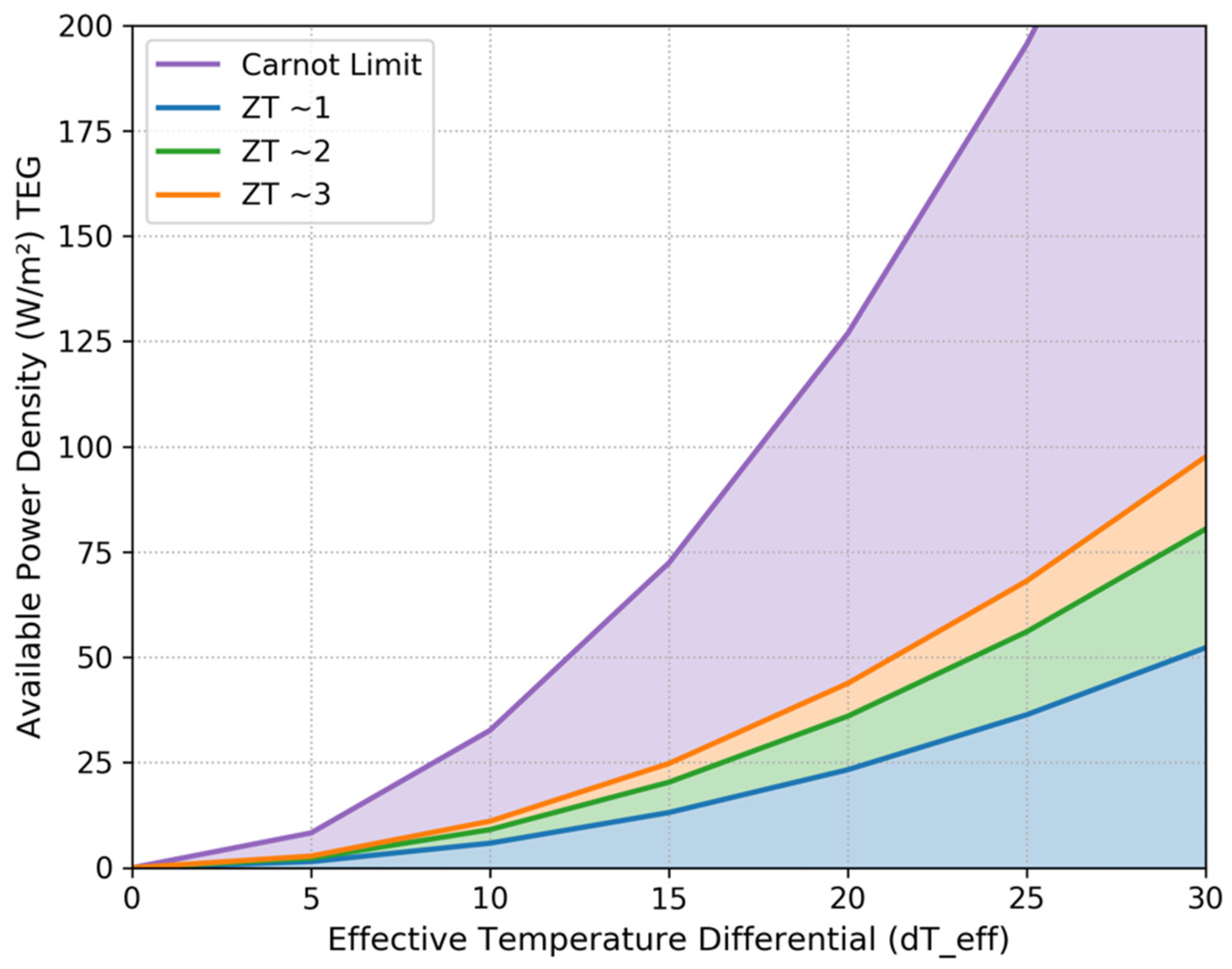
Examining Equation (33), it becomes apparent that each of the device efficiency, input heat flow, and material figure of merit values are proportional to the temperature delta across the device.
Figure 11 illustrates the net effect of the superposition of these relations, which is that the available power density increases exponentially with increasing temperature gradient.
In ambient building applications, this phenomenon leads to relatively limited available energy. However, as discussed in
Section 2.6, there are certain compelling cases for TEG energy harvesting, in which creative engineering is required to maximize the harvesting capacity of this technology. Data centres present one application that is highly desirable due to the large volume of waste heat produced with nearly 100% reliability.
3.5. Motor Generator
Electric motor generators are the final technology discussed, which are useful in the conversion of rotational kinetic energy into electric current. Motor typologies can be broken down into the following three categories [
89]:
DC Brushed Motors;
AC Induction Motors;
AC Synchronous Motors.
DC brushed motors are the original motor typology and utilize brushes, or mechanical commutators, to enable direct current operation. This motor type is seldom implemented today due to maintenance requirements and performance losses associated with the brush system. Induction motors are popular for their low cost due to the lack of magnetic material required, as both input energy and excitation is provided by stator winding current. The operation of an induction motor is characterized by asynchronous rotation of the rotor with respect to the stator magnetic field, with the differential between the two known as the slip speed. For this type of motor to act as a generator, the slip speed must be negative, i.e., the rotor must be driven at a speed faster than that of the stator magnetic field. Induction generators are not well suited to standalone applications, as an excitation current is required to produce power. Synchronous motors may be characterized by either permanent magnet, or wound rotor designs, with permanent magnet (PM) being the preferred typology for distributed applications and wound rotors dominating the utility power system. PM motors are commonly described in industry as brushless DC motors, as they are generally inverter controlled to produce variable speed and thus accept DC input; however, their operation is inherently AC. This topology is generally most desirable for energy-harvesting applications as the excitation is magnetic, and a simple mechanical input into the shaft can produce an electric current.
In order for high efficiency generation to be achieved with a PM synchronous motor, the motor characteristics must be well matched to the mechanical inputs, characterized by torque and rotational velocity. If the speed of rotation is insufficiently compatible with generator characteristics to be directly utilized, a mechanical power train must be employed to condition the velocity and torque acting at the generator shaft. Motor characteristics depend on the strength of the internal magnetic field, which is a function of magnetic material utilized, as well as the rotor and stator geometry. A motor’s operation can be characterized by the motor constant,
k, which relates speed to voltage and torque to current in accordance with Equations (34) and (35);
where
emf is the electromotive force in volts,
ω is the rotational velocity in radians per second,
τ is the motor torque, and
Ia is the armature current.
Consistent across the surveyed technologies is the fact that harvestable power is maximized at optimal load resistance. This points to the importance of maximum power-point-tracking control systems in all energy-harvesting circuits, such as those popularly applied to wind and solar applications, to optimize the output of the harvesting device regardless of downstream load characteristics, which may vary with time.
