1. Introduction
Residential and commercial buildings account for 36.9% of primary energy use, 74% of electricity consumption, and 35% of carbon emissions [
1,
2] in the United States. Thermal energy-related equipment is a major energy consumer, using ~17 quads of primary energy (e.g., natural gas, petroleum, thermal energy, coal, etc.) and producing 788 megaton of CO
2 emissions [
3]. The building’s thermal load, encompassing heating and cooling demands, represents a significant portion of a building’s overall energy consumption, affecting both operational efficiency and energy costs [
4].
Vapor compression systems are integral to building heating, cooling, and refrigeration, providing efficient temperature control across various applications. These systems operate by compressing a refrigerant, which then cycles through a condenser and evaporator to absorb and release heat, effectively transferring energy to achieve the desired thermal effect. In heating applications, heat pumps—a type of vapor compression system—extract heat from the outside air or ground, even in cold conditions, and transfer it indoors, offering an energy-efficient alternative to traditional heating methods. In cooling and refrigeration, vapor compression systems remove heat from indoor air or refrigerated spaces, maintaining comfortable temperatures and preserving perishable goods. Their versatility, reliability, and efficiency make them a cornerstone of modern heating, ventilation, air conditioning, and refrigeration (HVACR), essential for residential, commercial, and industrial environments. In vapor compression systems, the evaporator plays a crucial role by absorbing heat from the surrounding environment, allowing the refrigerant to evaporate and cool the air or space. This process is essential for effective cooling in air conditioning and refrigeration applications. However, ice and frost formation on the evaporator coils can pose significant issues. When moisture in the air freezes on the coils, it can insulate the surface, reducing heat transfer efficiency and causing the system to work harder, leading to increased energy consumption and potential system malfunction. Proper defrost mechanisms and maintenance are critical to preventing these issues and ensuring optimal system performance, necessitating an energy-intensive defrosting process that consumes a significant amount of energy [
4]. This defrosting process interrupts cooling, extends compressor run time, and reduces overall energy efficiency. Commercial refrigeration systems employ various defrost methods like off-cycle, electric, and hot gas defrost [
5]. These methods differ in efficiency, with annual defrost energy use around 300–540 kWh per refrigerated food display case.
Refrigeration is a significant electricity consumer. Improving refrigeration efficiency offers substantial potential for reducing energy consumption and carbon emissions. Additionally, ice is crucial as a direct-use product in industries such as food service, hospitality, health care, domestic refrigeration, cold-chain logistics, and food retail. Ice forms include cubes (both cloudy and clear), crescents, cylinders, spheres, flakes, tubes, and rectangular blocks. Residential ice makers found in refrigerators and portable units can produce 1.4–11.3 kg (3–25 lb.) of ice daily. Commercial ice makers produce 15.9–226.8 kg (35–500 lb.) daily for medium-scale applications, whereas daily industrial-scale ice production ranges from 4535.9 to 18,143.7 kg (10,000 to 40,000 lb.) for shipping, food, and medical uses [
5]. Ice-making involves a refrigeration cycle with an evaporator, condenser, compressor, and throttle valve. Energy consumption for ice makers varies from 0.2 to 50 kW, with an energy footprint of up to 11 kWh per 100 kg of ice. About 30% of this energy is used for dispensing or de-icing, consuming 3.3 kWh per 100 kg of ice [
6,
7].
Energy-efficient methods for defrosting and de-icing are hence crucial in reducing the overall energy consumption of buildings. Traditional defrosting techniques often require substantial energy, particularly in HVACR systems and in refrigeration units. By employing advanced materials and innovative technologies such as ultrasonic vibration to minimize ice adhesion and facilitate efficient ice removal, buildings can significantly lower energy use. This not only enhances system performance and longevity but also contributes to lower operational costs and reduced environmental impact.
In recent years, the high-power ultrasound technique has been used for de-icing owing to its high energy efficiency and nonthermal characteristics. High-power ultrasound de-ices surfaces by generating rapid vibrations and localized heating. This causes mechanical stress, microcracks, and acoustic cavitation, which weaken ice adhesion and facilitate removal [
8]. Compared with traditional heating methods, this method is more energy-efficient and less damaging to equipment. Venna et al. [
9] proposed using piezoelectric transducers to excite shear and impulse force at a low frequency of 1000 Hz for the de-icing of aircraft structures, and demonstrated that using both shear and impulse force could shorten the de-icing time by 40%, compared with the time required for using only shear force. Palacios et al. studied thin piezoelectric disks for de-icing on steel plates and measured the average shear strength of freezer ice to steel at −10 °C to be 1.5 MPa. The results indicate that the minimum power density to remove thin ice at −20 °C was about 0.07 W/cm
2 [
10], whereas wind-tunnel impact ice needed a higher power density of 1.2 W/cm
2 because the shear stress between ice and steel plate was predicted to be a higher value of 5 MPa [
11]. The design of the ultrasonic actuator was optimized through preliminary finite element modeling to determine the optimal frequency, mode, and shear adhesive strength [
10,
12]. Habibi et al. proposed combining the high-power ultrasonic guided wave and low-frequency vibration for the de-icing of turbine blades, because the ultrasonic guided wave can propagate a longer distance, thereby introducing shear stress for debonding the ice, and the low-frequency vibration is able to provide external shaking of the structure for removing ice [
13]. Whereas most studies used single-frequency continuous actuation, DiPlacido et al. [
14] studied multifrequency tone burst actuation to improve the efficiency of de-icing a plate structure. They found that using multiple tone bursts at different frequencies could increase the de-icing performance by a factor of four compared with continuous actuation on a benchtop testing with freezer ice. Other than using only high-power ultrasound, some studies [
15,
16,
17] proposed combining a treated surface or coating and high-power ultrasound for ice protection; the coating could reduce the surface adhesive strength, and the ice could be removed easily by the high-power ultrasound. Most studies of ultrasonic de-icing were applied to aircraft structures or wind turbines, whereas limited works were studied for HVACR systems, which also consist of plate and tube structures. The application of high-power ultrasound for removing ice in HVACR components needs to be investigated to provide insights on optimizing de-icing techniques that can lead to improved energy efficiency.
This study investigates the application of ultrasonic waves to the unique geometries and materials commonly found in HVACR components, with a focus on improving de-icing performance through detailed numerical simulations. By modeling ultrasonic wave propagation across representative structures—including plate, tube-and-fin, cylinder, and cube geometries—this work aims to provide a deeper understanding of how ultrasonic wave interacts with these configurations. Simulations were conducted using pressure excitation over a circular/rectangle area to replicate the real ultrasonic actuator, allowing for systematic evaluation of excitation frequency, amplitude, and location. Out-of-plane displacement is used as the key metric to quantify de-icing effectiveness across different scenarios. The primary goal is to reveal how these parameters influence ultrasonic de-icing performance and to offer practical guidelines for implementing ultrasonic actuators in HVACR structures. Moreover, the insights gained are expected to be broadly transferable to other ice-related structures beyond HVACR applications.
2. Ultrasound for De-Icing
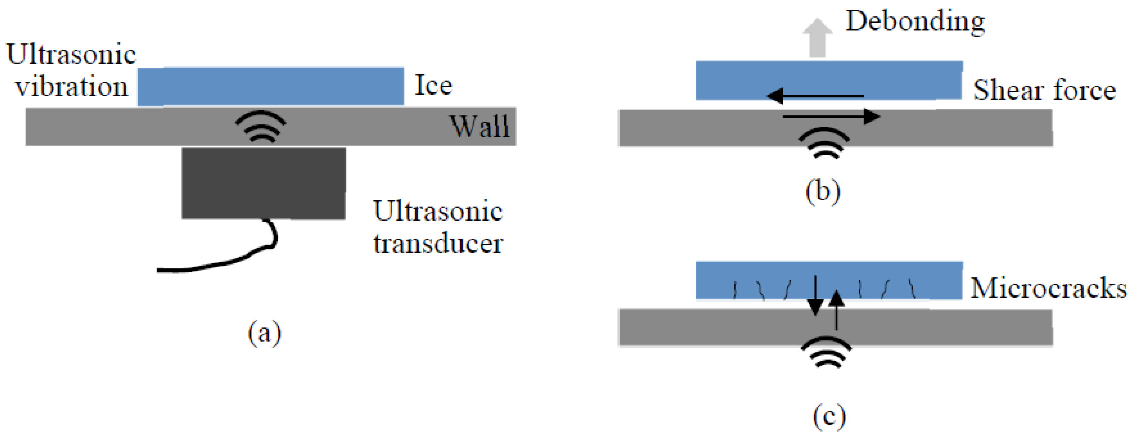
The basic principle of using high-power ultrasound for de-icing involves the application of ultrasonic waves to create rapid, high-frequency vibrations on the surface of the ice-covered area (
Figure 1a). These vibrations may generate mechanical stress in two directions from two vibration modes: extensional mode and flexural mode. In the extensional mode, the shear stress along the plate plane will create a debonding effect for the thin layer of ice (
Figure 1b), whereas in the flexural model the tensile stress caused by the plate bending will generate microcracks in the ice layer (
Figure 1c) [
18,
19,
20]. Both stresses will weaken the adhesion of the ice layer to the underlying surface. The generation of shear stress requires a shear-mode ultrasonic actuator, such as a radial-mode piezoceramic disk, while stress perpendicular to the plane is produced by a longitudinal (thickness-mode) piezoceramic disk. To the best of the author’s knowledge, thickness-mode actuators are generally more common (low-cost and easily available) than shear-mode ones and have larger piezoelectric coefficients, making them more efficient in general applications. Studies have shown that thickness-mode actuators often demonstrate higher efficiency compared to shear-mode actuators. In this work, the focus is on simulating flexural-mode ultrasonic wave propagation generated by the thickness-mode actuator (
Figure 1c), which induces microcracks and fractures in ice patches during the de-icing process.
Meanwhile, ultrasonic energy penetrates the ice, causing localized heating and acoustic cavitation [
21]. Cavitation is the formation and collapse of bubbles within the liquid or ice, which creates intense localized pressure. This process disrupts the structural integrity of the ice, making it easier to break apart and remove. The combined effects of mechanical vibration and cavitation efficiently break the bond between the ice and the substrate’s surface, facilitating its removal without requiring excessive heat or manual scraping. In addition to mechanical disruption, the thermal effects of high-power ultrasound contribute to its de-icing capability. The localized heating generated by ultrasonic waves helps to slightly melt the ice at the interface, further reducing its adhesion to the surface [
10]. The heat generated may not contribute to the ice interface melting if the interface temperature is a negative temperature. The effectiveness of this localized heating depends on the power level of the ultrasound generated. The mechanical stress and cavitation are the dominant effects in the de-icing process using high-power ultrasound.
High-power ultrasound provides a more targeted, efficient approach to de-icing, as it focuses energy directly on the ice, with less wastage than that of existing de-icing methods using electric heating or hot gas defrost. Due to its efficiency, ultrasonic de-icing is widely used in critical applications like aircraft wings and blades [
15,
19,
22], electricity transmission lines [
23,
24], wind turbines [
25,
26], and marine vessels [
27]. The use of ultrasound for de-icing not only enhances energy efficiency but also reduces wear and tear on equipment surfaces, offering a more sustainable and cost-effective solution for various applications, including heating, cooling, refrigeration, aviation, and infrastructure maintenance.
However, when applying high-power ultrasound for de-icing, several key factors must be carefully considered. First, selecting the correct excitation frequency and waveform is crucial for each specific structure and ultrasonic actuator. The optimal frequency and waveform can typically be identified through preliminary experiments or simulations, but this process requires professional expertise and experience, which may limit broader adoption of the technology. Additionally, the performance of ultrasonic actuators can decline in low-temperature environments compared to room temperature. Over time, repeated cycles of high-voltage excitation can lead to fatigue in the piezoceramic material, reducing the overall de-icing efficiency. For plate structures, an ultrasonic actuator disk is commonly used, but a single disk has a limited effective range. To achieve optimal de-icing performance across a larger area, multiple actuators are often necessary to provide adequate coverage and ensure efficient ice removal.
3. Finite Element Modeling and Analysis
Four different ice-making structures are simulated under ultrasonic excitation for ultrasonic de-icing purposes. The first type of structure is a plate, which is widely used in freezing, cold-chain, and commercial kitchen equipment. The second type is a tube-and-fin structure selected as a representative structure for heat exchangers used in vapor compression-based HVACR systems. The third type is a tube structure, and the fourth is a rectangular ice mold. The latter two structures are commonly used in commercial ice makers. As discussed in previous sections, two ultrasonic wave modes are commonly studied for de-icing: the extensional mode, which generates shear stress for ice debonding, and the flexural mode, which produces tensile stress for ice cracking. The literature [
19] compares the de-icing efficiency of these two modes, indicating that, at a given frequency and displacement, the flexural mode can produce greater shear and tensile stresses than the extensional mode while the tensile stress is dominant for the flexural mode. Additionally, the flexural mode requires less power [
28] and is more readily excited by commercially available piezoelectric actuators [
19]. Therefore, this work will focus on numerical simulations of the flexural mode for ultrasonic de-icing. According to previous studies [
18,
29], ice cracking is primarily driven by out-of-plane displacement in the flexural mode. Thus, in this work, the out-of-plane displacement will be used as a key parameter to evaluate the behavior of ultrasound on these structures for de-icing purposes. To simplify the analysis, ice will not be included in the simulation, and the focus will be on wave propagation within HVACR structures to excite the ultrasonic flexural mode for de-icing. Additionally, simulating the ice layer is unnecessary because the goal is to activate the de-icing function when the ice layer is thin and weak. In this state, the thin ice layer has minimal impact on the overall weight and stiffness of the HVACR structure.
3.1. Plate Structure Under Ultrasonic Excitation
A copper plate with a thickness of 2 mm was used to simulate the response under ultrasonic excitation in Abaqus [
30]. The density of the copper is 8.94 × 10
3 kg/m
3, the elastic modulus is 130 GPa, and the Poisson’s ratio is 0.34. These mechanical parameters are consistently applied to the copper materials in the subsequent sections. Copper material is selected in this work because copper is widely used in the HVACR system due to its excellent thermal conductivity, stable behavior, compatibility with refrigerants, and easy fabrication.
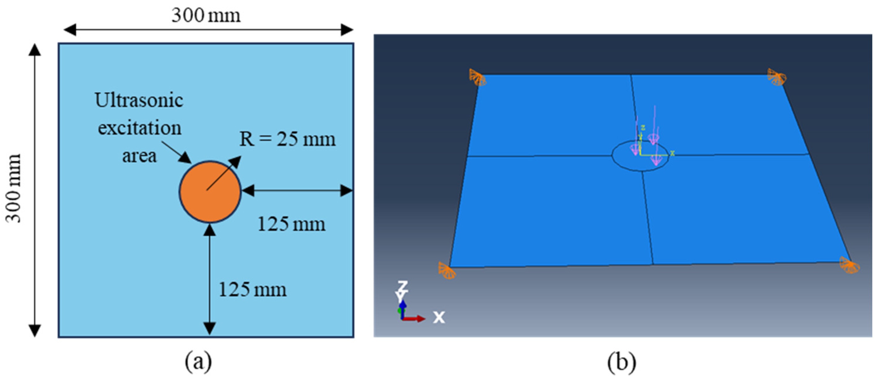
Figure 2a shows the dimensions of the copper plate and the ultrasonic excitation area. The plate measures 300 × 300 mm, with ultrasonic excitation applied at its center within a 25 mm radius. The Abaqus model is illustrated in
Figure 2b, with the plate simulated as a shell. The boundary conditions fix the four corners with zero displacement in the X-, Y-, and Z-directions, where the Z-direction is perpendicular to the plate plane. Before applying ultrasonic excitation, the plate’s resonance frequencies were analyzed for the first 10 modes, which ranged from 29 to 334 Hz. Given that the ultrasonic excitation frequency is between 20 and 60 kHz—far from the fundamental resonance frequencies—local resonance is excited, rather than global resonance, which is more effective for de-icing. The resonance frequency of the ultrasonic actuator used is around 40 kHz, so the excitation frequency of 40 kHz was used for this work. A pressure load with a sinusoidal function of 40 kHz and an amplitude of 1 MPa was applied to the center circular area. Since the goal of the excitation is to simulate flexural-mode wave propagation within the plate, the excitation frequency is intentionally set far from the global resonance frequency. As a result, the boundary constraints have minimal impact on the simulation outcomes. The ultrasonic excitation is modeled using a continuous sinusoidal pressure load, though applying a displacement-based excitation is also a viable option for simulating the wave behavior.
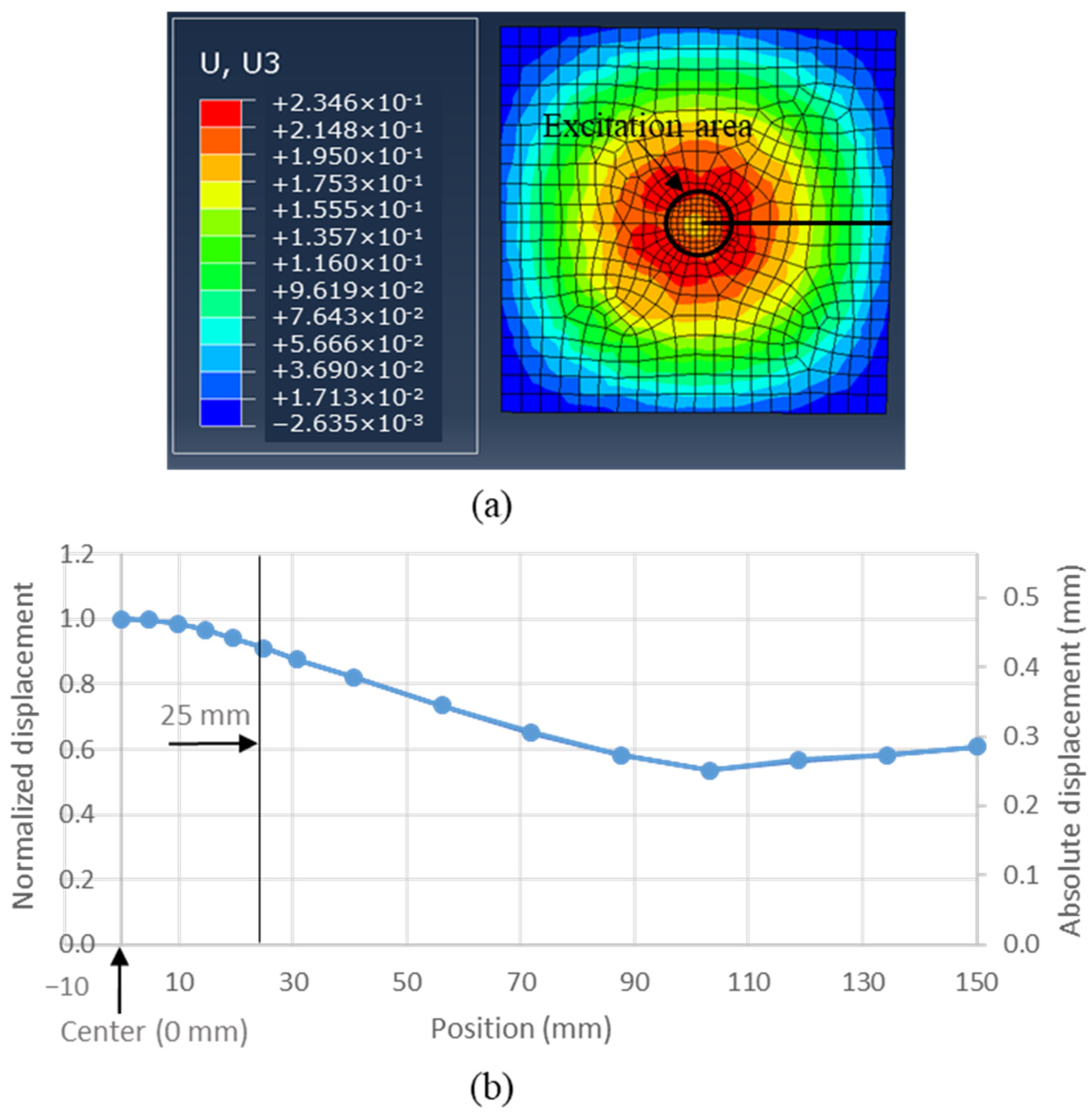
Figure 3a shows the displacement field map at 0.3 s of the copper plate under the ultrasonic excitation at a frequency of 40 kHz. The maximum displacement in the Z-direction is located at the center of the excitation area. The displacements were picked up at multiple points from the center to the edge of the plate (nodal points on the horizontal line in the figure). Maximum displacement was acquired from the displacement history at each nodal point.
Figure 3b plots the displacements at different points versus the corresponding locations with the left y-axis for normalized displacement and the right y-axis for the absolute displacement; the center of the excitation area is 0 mm of the position axis, whereas the right edge point is 150 mm. All the displacements were normalized by the displacement at the center position.
At a distance of 25 mm from the center, where the boundary of the excitation area is located, the displacement is still 91% of the maximum displacement. At 50 mm, which is twice the excitation radius, the displacement remains at 75% of the maximum displacement. The minimum displacement occurs at 103 mm from the center, measuring 53.5% of the maximum displacement. Even at the edge of the plate (150 mm), six times the excitation radius, the displacement retains 60.8% of the maximum displacement. These results suggest that ultrasonic excitation can generate significant vibrations over a relatively large area, extending up to six times the radius of the excitation area, with displacements decreasing to approximately53% of the maximum. Therefore, the ultrasonic actuator shows the capability to generate an ultrasonic wave propagating to a large area that could be potentially used for de-icing purposes on plate structures.
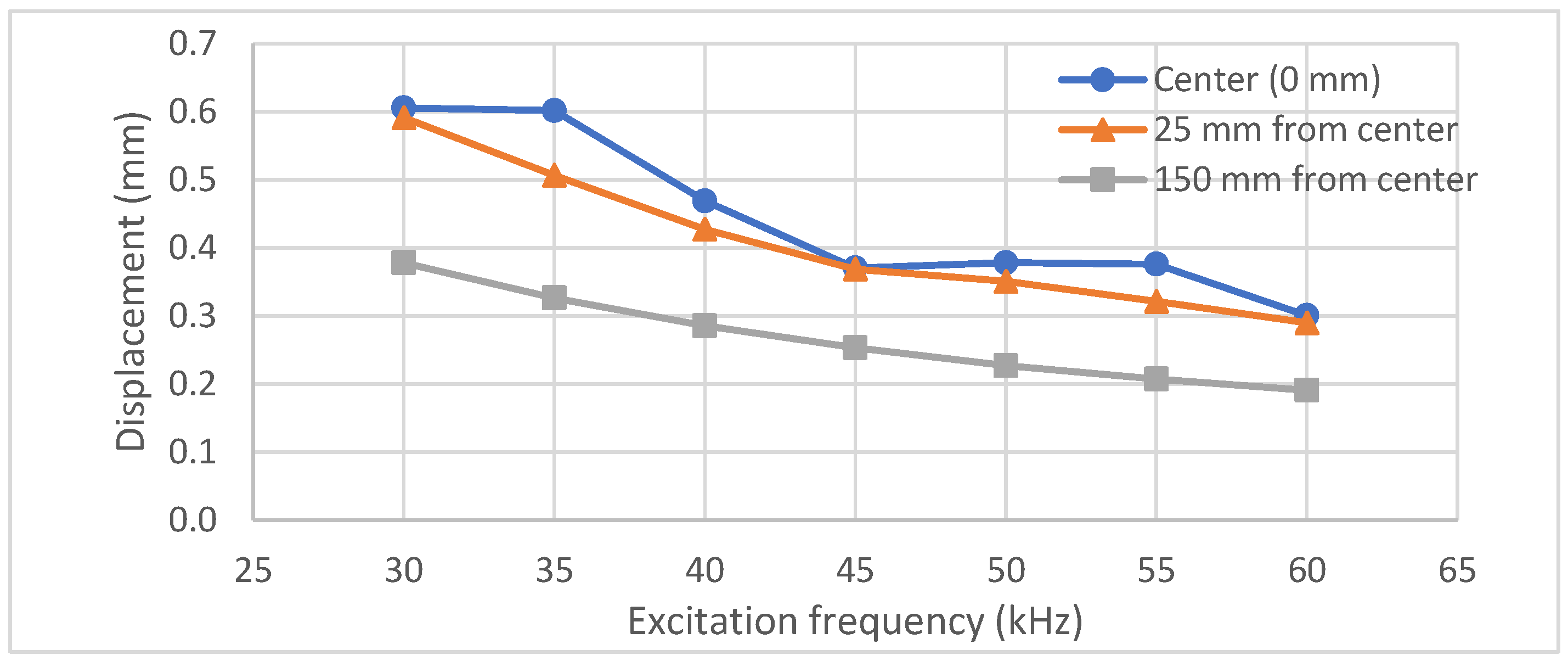
The simulation was repeated with varying excitation frequencies ranging from 30 to 60 kHz in increments of 5 kHz.
Figure 4 illustrates the displacement results at three locations: the center of the plate (0 mm), the boundary of the excitation area (25 mm from the center), and the edge of the plate (150 mm from the center). Across all three locations, the displacement shows a decreasing trend with increasing excitation frequency. This indicates that, given the same amplitude of excitation loading, the plate experiences more significant displacement at lower excitation frequencies. However, the selection of the optimal frequency for practical applications also requires considering the resonance characteristics of the ultrasonic actuator used.
To determine the optimal placement of ultrasonic actuators, simulations were conducted using three plates equipped with varying numbers of actuators: one, two, and four. Each actuator configuration served as the excitation source for the plates. The displacement field results for each scenario are illustrated in
Figure 5a–c, where the black circles denote the actuators’ excitation areas. The input power to the piezoelectric transducer is proportional to the square of the applied voltage
, and the voltage is linearly proportional to the force
generated on the plate. Therefore, to maintain a consistent power input across all scenarios, the excitation amplitudes were adjusted to 1 MPa,
MPa, and 0.5 MPa for one, two, and four actuators, respectively. The maximum displacements were recorded at mesh grid points from the plate’s center to its edge and plotted in
Figure 5d for all three scenarios. As shown in the figure, compared with using a single actuator, using multiple actuators results in larger displacements at the sensing points, despite having the same power input. The configuration with four actuators achieved the largest displacement between 0 and 100 mm, with only a slight difference compared with the two-actuator setup beyond 100 mm. The displacement produced by two actuators was comparable to that of one actuator within the 0–50 mm range. However, beyond 50 mm, the two-actuator setup demonstrated superior displacement compared with that of a single actuator. Additionally, the displacement field images for the three scenarios in
Figure 5a–c indicate that the four-actuator setup appears to have a larger effective area than that of the other configurations. Therefore, using more actuators (rather than a single actuator) can generate a larger out-of-plane displacement for a plate, enhancing de-icing performance under the same total power input. However, this also increases the cost and complexity of the de-icing system.
3.2. Tube-and-Fin Structure Under Ultrasonic Excitation
The tube-and-fin structure, depicted in
Figure 6a, is a common type of heat exchanger. This component’s sides are two thick aluminum plates, which support the copper tubes and aluminum fins. The copper tubes run through both the plates and the thin aluminum fins. The basic principle of ultrasonic de-icing involves applying ultrasonic excitation to either the side plates or the copper tubes. This excitation causes vibrations to propagate through the copper tubes and onto the fins, effectively removing ice from the tubes, fins, and structural support plates.
A simplified Abaqus model, shown in
Figure 6b, was created for this study. The copper tubes are 50 mm long, with a diameter of 10 mm and a thickness of 2 mm. The side plates and fins are both 40 × 40 mm in size and made of aluminum. The plates are 2 mm thick, whereas the fins are significantly thinner at 0.3 mm. The copper has an elastic modulus of 130 GPa, a Poisson’s ratio of 0.34, and a density of 8.94 × 10
3 kg/m
3. The aluminum has an elastic modulus of 69 GPa, a Poisson’s ratio of 0.334, and a density of 2.7 × 10
3 kg/m
3.
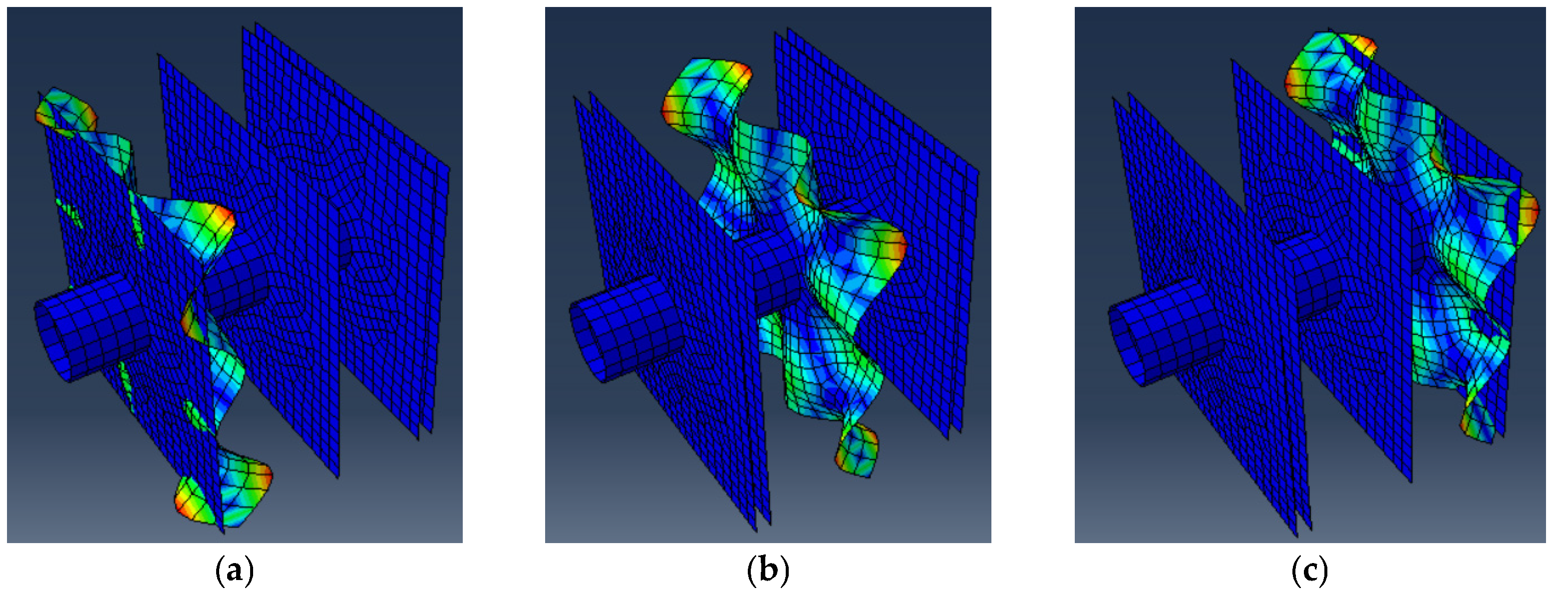
A resonance analysis was conducted on the model, revealing that the first 10 resonance frequencies ranged from 1149 to 3395 Hz. The ultrasonic excitation frequency range was set much higher than these fundamental resonance frequencies to avoid global vibrations of the entire structure. The resonance frequencies and modes in the frequency range of 40–50 kHz were also analyzed. Researchers found that, at specific resonance frequencies, only one of the fin plates showed deformation, whereas the other parts did not have deformation.
Figure 7 shows the three resonance modes; only the fin plates showed deformation, whereas the other structural parts did not. The resonance frequencies for the three modes in the figure are very close, from 44,582 to 44,584 Hz.
Two loading scenarios were analyzed with different loading locations to assess the effect of ultrasonic excitation on the de-icing performance. In the first scenario, ultrasonic excitation was applied to the side aluminum plate with a pressure of 1 MPa, as illustrated in
Figure 8a. In the second scenario, the excitation was applied to the end-tube surface as a shear traction of 1 MPa, as shown in
Figure 8b. The simulation results for these two scenarios are depicted in
Figure 9, with both displacement maps using the same color scale limits for direct comparison.
The results demonstrate that ultrasonic vibrations propagate throughout all components, including the fins, tube, and side plates, suggesting that excitation at one end of the structure could potentially remove ice from the opposite end. However, the efficient range of this effect requires further investigation. Notably, the structure under excitation on the side plate (
Figure 9a) exhibits significantly higher displacement compared with the scenario with excitation on the end tube. This difference can be attributed to the larger loading area of the side plate compared with the limited area available on the end tube for excitation. In practical applications, mounting ultrasonic actuators on the side plates might prove to be more effective and efficient for de-icing.
3.3. Tubular and Rectangle Structure Under Ultrasonic Excitation
A tube structure, commonly used in small-size ice makers to produce hollow cubes with finger-like dimensions, was analyzed.
Figure 10a depicts one of the ice molds from a small commercial ice maker used during lab testing. In the Abaqus simulation, a single finger segment was modeled and analyzed under ultrasonic excitation, as illustrated in
Figure 10b. The model consists of a horizontal rectangular tube positioned above a vertical circular tube. The horizontal tube measures 35 mm in length, with cross-sectional dimensions of 10.5 × 14 mm. Directly beneath it is the vertical tube, which has a diameter of 10 mm and a height of 33.5 mm. Both the horizontal and vertical tubes feature a uniform wall thickness of 0.5 mm.
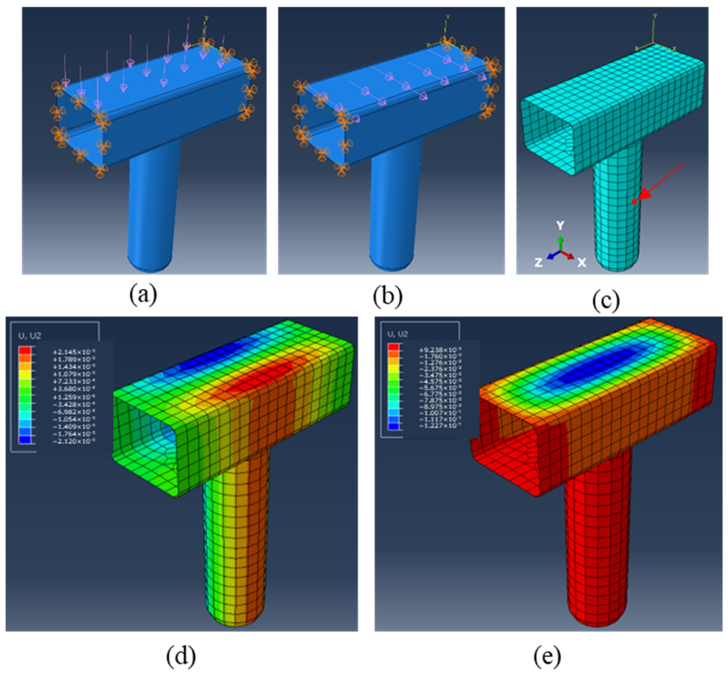
Two loading modes, corresponding to the ultrasonic excitation modes from the ultrasonic actuators, were analyzed for their effectiveness in de-icing. In both scenarios, the loading was applied to the top surface of the segments. The first mode involves vertical loading induced by a thickness-mode ultrasonic actuator, as shown in
Figure 11a. The second mode features horizontal loading induced by a shear-mode actuator, as depicted in
Figure 11b. The ice cube forms around the finger tube, and effective de-icing depends on creating substantial displacement on the finger-tube surface in the Y-direction. Therefore, to compare the two loading modes, displacement from a sensing point at the middle height of the finger tube was analyzed, as illustrated as the red dot in
Figure 11c. The resulting displacement field for the segment is displayed in
Figure 11d,e. For vertical loading, the maximum displacement in the Y-direction at the sensing point was found to be 7.3 × 10
−3 mm. In contrast, the maximum displacement for horizontal loading was only 1.6 × 10
−3 mm. These results indicate that vertical loading, excited by the thickness-mode ultrasonic actuator, is more efficient for de-icing the finger mold. However, note that the maximum displacement on the simulated segment is two orders of magnitude smaller than that of the displacement observed on the plate structure. Consequently, a higher power may be necessary for effective de-icing on the finger mold compared with de-icing on the plate structure.
The rectangle mold is another commonly used mold for making cubes in ice makers.
Figure 12a shows a rectangle mold used in lab testing. The mold consists of a copper body with a thickness of 0.91 mm, and it is coated with nickel. Ultrasonic excitation can be applied only on the top and side surfaces because the back surface is inaccessible. The simulation focuses on a single row of the rectangular mold. Two scenarios were simulated: one with ultrasonic excitation applied only to the top surface (
Figure 12b), and another with excitation applied to both the top and side surfaces (
Figure 12c). In each scenario, the loading on each surface area was set to 1 MPa, consistent with previous studies.
The simulation results are presented in
Figure 12d,e, with both displacement field maps using the same color scale for direct comparison. The results indicate that applying ultrasonic excitation to both the top and side surfaces results in more significant displacement in the rectangular mold than the displacement that results from applying ultrasonic excitation only to the top surface. Notably, larger displacements were observed in the vertical separators, highlighted in
Figure 12e. The bottom plates of the mold also exhibited more significant displacement with additional side surface excitation. These large displacements could enhance the de-icing performance by effectively breaking the boundary between the ice and the mold surfaces. Given the limited surface area of the rectangular mold for applying ultrasonic excitation, using multiple ultrasonic actuators at different locations is recommended to improve the overall de-icing performance.


