Article

Performance Improvement of Proton Exchange Membrane Fuel Cells with a TiO2 Sputtered Gas Diffusion Layer Under Low-Humidity Conditions

1
Department of Mechanical Engineering, Dankook University, 152 Jukjeon-ro, Suji-gu, Yongin-si 16890, Gyeonggi-do, Republic of Korea
2
Department of Chemistry & Biochemistry, University of California San Diego, 9500 Gilman Dr, La Jolla, CA 92093, USA
*
Authors to whom correspondence should be addressed.
Energies 2025, 18(6), 1525; https://doi.org/10.3390/en18061525
Submission received: 24 February 2025 / Revised: 9 March 2025 / Accepted: 17 March 2025 / Published: 19 March 2025
(This article belongs to the Special Issue Sustainable Development of Fuel Cells and Hydrogen Technologies)

Abstract

:
Proton exchange membrane fuel cells (PEMFCs) are pivotal to advancing sustainable hydrogen energy systems. However, their performance decreases under low-humidity conditions (relative humidity, RH 50%) due to inadequate membrane hydration. This study addresses this challenge by utilizing a sputtering process to deposit titanium dioxide (TiO2) onto microporous layers (MPLs), enhancing their hydrophilicity and water management capabilities. TiO2 intrinsic hydrophilic properties and oxygen vacancies improve water adsorption and distribution, leading to more stable PEMFC performance under reduced humidity. Electrochemical evaluations revealed that while initial resistance slightly increased, long-term stability improved significantly. The TiO2-coated MPL exhibited a lower performance degradation rate, with a 12.33% reduction in current density compared to 25.3% for the pristine MPL after 10 h of operation. These findings demonstrate that TiO2 deposition effectively mitigates performance losses under low-humidity conditions, reducing the reliance on external humidification systems. This work contributes to the development of more efficient and sustainable fuel cell technologies for applications such as hydrogen-powered vehicles and distributed energy systems.

1. Introduction

Proton exchange membrane fuel cells (PEMFCs) are integral to a broad range of applications, such as powering hydrogen fuel cell vehicles, portable devices, and stationary power systems. Their high energy efficiency, compact design, quick start-up, and zero harmful emissions make them a pivotal technology for achieving carbon-neutral energy solutions [1,2,3,4,5,6,7]. However, hydrogen is not abundantly available in nature, and its current production is largely reliant on fossil fuel-based processes, which result in significant carbon emissions. To address this issue, green hydrogen production via water electrolysis using renewable energy has emerged as a promising solution. Furthermore, while renewable energy sources such as solar and wind power are viable alternatives to fossil fuels, their intermittency and fluctuation limit large-scale deployment.
Hydrogen serves as an efficient energy carrier that can store excess renewable energy, thus providing a stable and sustainable energy supply [8]. PEMFCs are particularly recognized for their potential to enable a hydrogen-based society, inspiring extensive research into improving their performance and durability. PEMFCs are particularly recognized for their potential to enable a hydrogen-based society, inspiring extensive research into improving their performance and durability. However, it should also be noted that the limited lifespan of PEMFCs still hinders their commercialization. Over prolonged operations, PEMFC performance gradually deteriorates due to complex operational conditions and component degradation, eventually reaching the minimum acceptable threshold. Key factors contributing to performance degradation include catalyst degradation, membrane thinning, water management issues, and mechanical stress on gas diffusion layers [9,10]. To address these challenges, prognosis and health management (PHM) strategies have been introduced to monitor and predict PEMFC lifespan, enabling proactive interventions to prevent failures. Fuel cell life prediction models, such as those considering the recovery phenomenon of reversible voltage loss, have been developed to enhance the reliability and longevity of PEMFCs.
These advancements are essential for ensuring the long-term viability of PEMFC technology in commercial applications [11,12]. At their core, PEMFCs generate electricity by electrochemically reacting hydrogen and oxygen. The polymer electrolyte membrane (PEM), a solid electrolyte, facilitates the conduction of hydrogen ions while serving as a barrier for electrons. Electrons generated during the reaction are transferred through an external circuit, producing electricity [1]. The combination of efficiency, clean energy generation, and versatility positions PEMFCs as a cornerstone technology for the sustainable energy transition. To achieve this performance, maintaining an optimal water balance within PEMFCs is critical. A typical PEMFC consists of several key components, including the PEM, catalyst layer, MPL, gas diffusion layer (GDL), and bipolar plates. Each of these components plays a distinct role in water and gas management, ensuring the system’s overall efficiency and durability. Especially, the PEM is a critical component that facilitates the transport of hydrogen ions (H+) generated at the anode to the cathode, while preventing gas and electron crossover. Therefore, ensuring the ion conductivity of PEM by maintaining an ideal hydration state is important for PEMFC performance and stability. Excessive water accumulation can lead to flooding, which hinders gas transport. Conversely, under low relative humidity (RH) conditions, the electrolyte membrane may dry out, resulting in decreased ionic conductivity, which ultimately causes performance and efficiency losses [13,14,15]. Under low-humidity conditions, the dehydration of the electrolyte membrane leads to increased ohmic resistance due to reduced proton conductivity. Furthermore, insufficient water content in the membrane causes mechanical stress and cracking, accelerating its degradation. The lack of water also affects the catalyst layer by reducing electrochemical reaction sites, while excessive drying leads to an imbalance in gas diffusion, resulting in concentration polarization. These effects collectively contribute to performance deterioration in PEMFCs operating under low humidity conditions [16,17].
For maintaining the PEM in an ideal hydration state, GDL, MPL, and a bipolar plate play an essential role. The GDL delivers fuel and oxidants to the catalyst layer through its porous structure while simultaneously expelling the produced water. The pore size and surface properties of the GDL directly influence the efficiency of water and gas transport. The microporous layer (MPL), positioned between the GDL and the catalyst layer, is typically coated with hydrophobic materials to promote water removal, maintain uniform water and gas distribution, and prevent flooding. The bipolar plate not only provides electrical connectivity between PEMFCs but also controls the flow of gases and water through flow fields, preventing water accumulation and facilitating water removal. The design of the bipolar plate directly influences water management efficiency and PEMFC performance, contributing to minimizing pressure loss and improving the uniformity of gas distribution. These components work together to maintain a balanced hydration state within the PEMFC, supporting stable and efficient electrochemical reactions [1,18,19,20,21]. Research aimed at improving water management performance has traditionally focused on membrane electrode assembly (MEA) and bipolar plates [22,23]. Various strategies, such as hydrophilic additives in the membrane, modified ionomers, and catalyst layer engineering, have been explored to improve PEMFC performance under low-humidity conditions [17,24]. While these approaches have shown promising results in enhancing proton conductivity and water retention, they often require complex synthesis processes or lead to trade-offs between conductivity and mechanical stability. Furthermore, these modifications alone may not fully address water distribution challenges across the entire fuel cell system, particularly in the gas diffusion layer (GDL) and microporous layer (MPL). Consequently, research on GDL/MPL modifications has gained increasing attention as a complementary approach. However, conventional GDL/MPL structures are often designed to promote water expulsion, and their inherent hydrophobicity can limit moisture retention, especially under extremely low-humidity conditions.
Therefore, novel modifications, such as hydrophilic material coatings or nanostructured surface engineering, are required to enhance water retention and improve PEMFC performance under dry operating conditions. Studies on the MEA have actively centered on enhancing the performance of the electrolyte membrane and catalyst layer, playing a crucial role in optimizing PEMFC performance [25]. The bipolar plate is a key component in PEMFCs, responsible for controlling the flow of gases and water. Traditionally, research has focused on improving water removal performance and gas transport efficiency through flow field designs [26]. In particular, enhancing the surface properties of the bipolar plate and optimizing flow field structures have significantly contributed to improved water management and performance stability [27]. Recently, complementing traditional studies, the GDL and MPL have gained attention for their critical roles in regulating the pathways of water and gas transport to enhance water management. Research aimed at improving the physical and chemical properties of the GDL and MPL complements studies on MEAs and bipolar plates, emerging as a new approach to stabilize PEMFC performance under low-humidity conditions. To enhance water management, various hydrophilic materials such as SiO2 and TiO2 have been explored, with TiO2 proving particularly effective due to its superior water adsorption capability and chemical stability [28,29,30,31,32]. Oxygen vacancies within the crystalline structure of TiO2 play a crucial role in adsorbing water molecules on its surface [33,34] These vacancies influence the electronic structure of TiO2, enhancing its ability to attract electrons. Such defects create spaces where electrons can move freely in oxygen-deficient regions, promoting interactions with surrounding electrons [35,36]. As a result, TiO2 enhances electrochemical activity and plays a crucial role in the moisture management of PEMFCs by adsorbing water molecules on its surface. Specifically, oxygen vacancies facilitate the bonding with water molecules, helping to supply sufficient moisture to the electrolyte membrane of PEMFCs [37]. These materials have been applied to PEMFC components through deposition techniques such as Atomic Layer Deposition (ALD), sputtering, and sol–gel methods [38,39,40,41]. Among these, sputtering is particularly advantageous due to its high deposition rate, uniform thin-film formation, and room-temperature process compatibility [42,43]. In this study, the sputtering process was utilized to deposit TiO2 (titanium dioxide) onto the microporous layer (MPL) to mitigate performance degradation in PEMFCs under low-humidity conditions [30,44]. The structural and electrochemical properties of the sputtered TiO2 layers were analyzed, and their impact on PEMFC performance was evaluated [36,37,45,46]. The PTFE (polytetrafluoroethylene) incorporated into the MPL plays a critical role in maintaining uniform moisture distribution within the electrolyte membrane of PEMFCs [24,45]. The combination of TiO2 and PTFE enhances the structural properties of the MPL, effectively improving its moisture adsorption and distribution capabilities [36,45]. This study demonstrated that the oxygen vacancies in TiO2 facilitate water adsorption in PEMFCs, enabling stable performance even under low-humidity conditions [33,47]. These findings are expected to contribute to the advancement of PEMFC technology by providing a more efficient and durable approach to water management [33,47].

2. Experimental

In this study, TiO2 was deposited onto the cathode MPL using a sputtering process, and its effect on the electrochemical behavior of PEMFCs was investigated. The TiO2 thin film was deposited on the MPL using reactive sputtering with a Ti target (VTM, Seoul, Republic of Korea) and a gas mixture of Ar and O2. During the deposition process, 100 W of RF power was applied to the Ti target, and the deposition rate of the TiO2 thin film was analyzed using a Si wafer as the substrate. RF power was chosen over DC power because it is more effective for sputtering partially insulating materials like TiO2. This choice prevents charge buildup on the target surface, ensuring a stable and efficient deposition process. TiO2 deposition was conducted at a pressure of 30 mTorr, and the sputtering process was performed at RT. To maintain the deposition pressure, Ar (99.999%, Samjung Energy, Paju, Republic of Korea) at 20 sccm and O2 (99.999%, Samjung Energy, Paju, Republic of Korea) at 2 sccm were supplied.
The PEMFC used in this study was composed of an end plate, bipolar plate, current collector, gasket, gas diffusion layer (GDL), and membrane electrode assembly (MEA). A membrane electrode assembly (MEA C Type, CNL Energy, Seoul, Republic of Korea) with an active area 23 × 22 mm2 was employed. The Nafion used in the MEA was NR-211 (Chemours, Wilmington, DE, USA), and the ionomer was D-521 (Chemours, Fayetteville, NC, USA). The Pt loading for both the anode and cathode electrodes was 0.4 mg/cm2, and a gas diffusion layer (GDL 39BB, SGL Carbon, Wiesbaden, Germany) was employed. For the cathode GDL, a TiO2 layer with a thickness of 30 nm was deposited based on the deposition rate determined using a Si wafer. The thickness range (20–40 nm) was selected based on previous studies, which demonstrated its effectiveness in enhancing surface hydrophilicity and maintaining structural stability [48,49]. This range has been experimentally verified to improve water retention and distribution in PEMFCs, ensuring better performance under low-humidity conditions. The bipolar plate (CNL Energy, Seoul, Republic of Korea) was made of graphite with a single-channel serpentine flow field, featuring a channel width of 1.0 mm and a depth of 0.8 mm. The configuration and layout of the PEMFC used in the experiments are illustrated in Figure 1.
The PEMFC was assembled with a tightening torque of 80 in·lb, and all performance evaluations were conducted at a cell temperature of 60 °C. A commercial fuel cell test station (Smart2 PEM, WonATech, Seoul, Republic of Korea) was employed. Humidified H2 was supplied to the anode using a bubbler, and humidified air was supplied to the cathode through the same method. The hydrogen (99.999%, Samjung Energy, Paju, Republic of Korea) was supplied at a flow rate of 100 sccm under a pressure of 150 kPa, while the air (N2 79% vol.%, O2 21 vol.%, Samjung Energy, Paju, Republic of Korea) was supplied at a flow rate of 300 sccm under the same pressure. In this study, membrane humidification was employed to supply moisture.
The electrochemical characteristics of the fuel cell were analyzed using a commercial potentiostat (SP-150, BioLogic, Seyssinet-Pariset, France) and a booster (VMP3B-10, BioLogic, Seyssinet-Pariset, France). Electrochemical impedance spectroscopy (EIS) analysis was conducted under a load condition of 0.8 V, with a frequency range of 100 mHz to 200 kHz and a sinusoidal signal amplitude of 10 mV. To analyze the electrochemical characteristics of the PEMFC, activation was performed under fully humidified conditions (RH 100%) for both the anode and cathode. Subsequently, the relative humidity was reduced to 50%, and the initial performance was evaluated using J-V-P curves and EIS. For durability comparison, the current density was measured under a constant voltage condition (0.4 V) for 10 h. Following the constant voltage test, J-V-P curves and EIS were measured again to assess performance. TiO2 was characterized using SEM-EDS (Scanning Electron with Energy-Dispersive X-ray Spectroscopy, Helios 5 UC, Thermo Fisher Scientific, Waltham, MA, USA), and the morphology of TiO2 deposited on the MPL surface was observed using SEM (Scanning Electron Microscope, Hitachi SEM S-5200, Hitachi High-Tech, Hitachinaka-shi, Japan). Additionally, contact angle measurements were performed to evaluate changes in surface wettability between the pristine MPL and the MPL coated with TiO2. Contact angle measurements were performed using a Phoenix-300 system (Phoenix Series, SEO, Suwon, Republic of Korea). A 2 µL water droplet was dropped onto the surface, and the left and right contact angles were measured to calculate the average value. This analysis quantitatively evaluated the changes in surface properties and water adsorption capacity resulting from the TiO2 deposition.

3. Results and Discussion

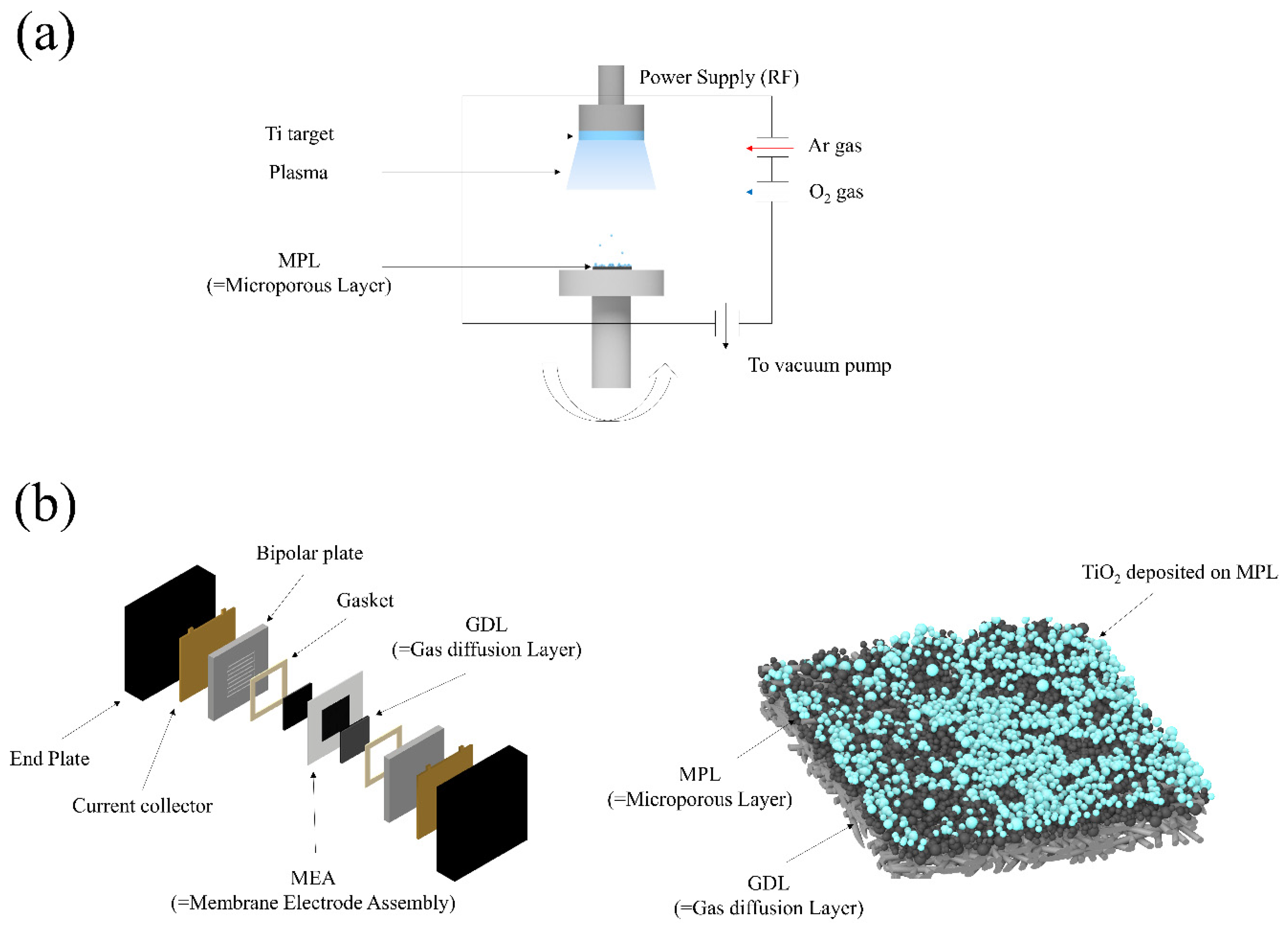
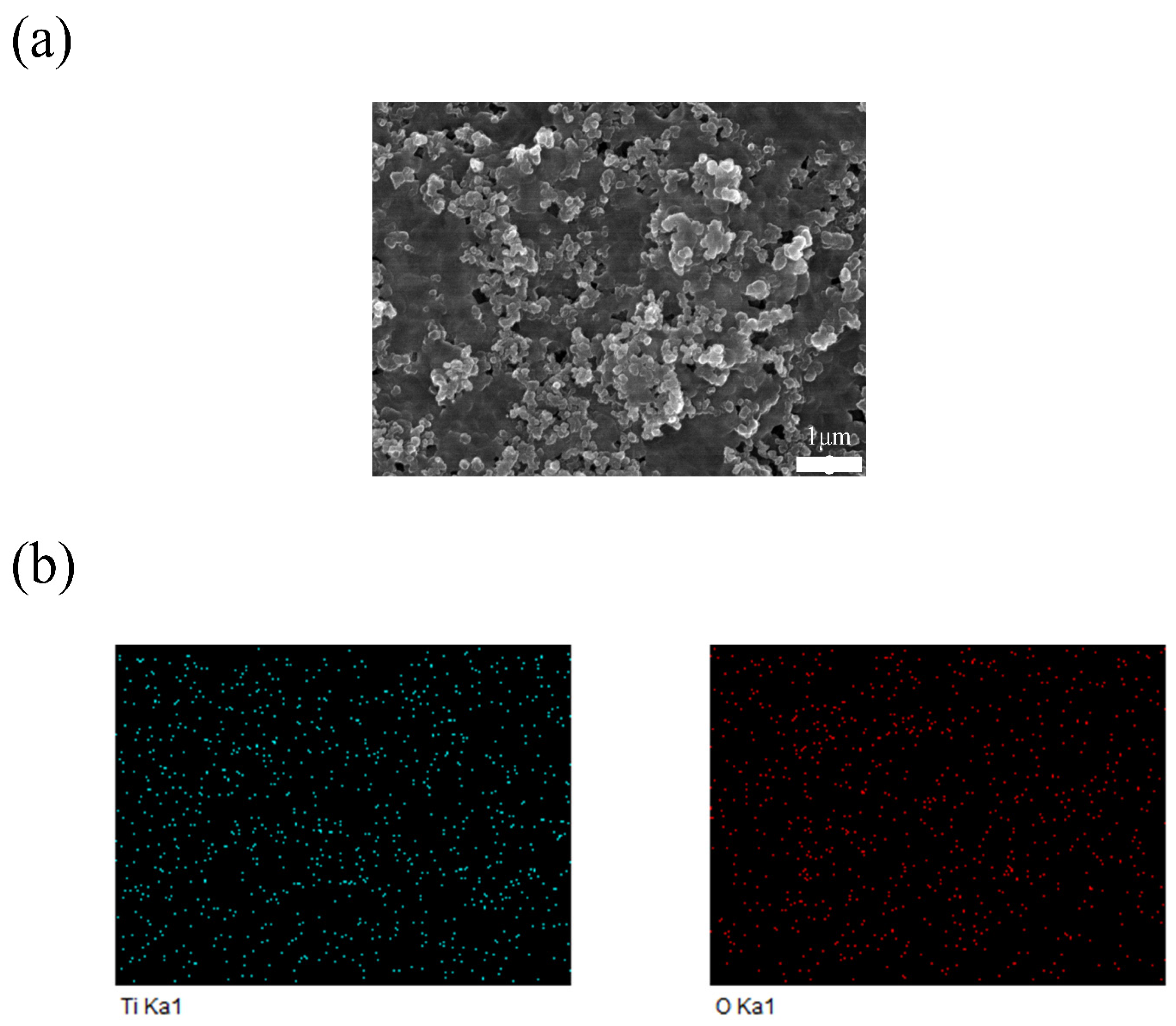
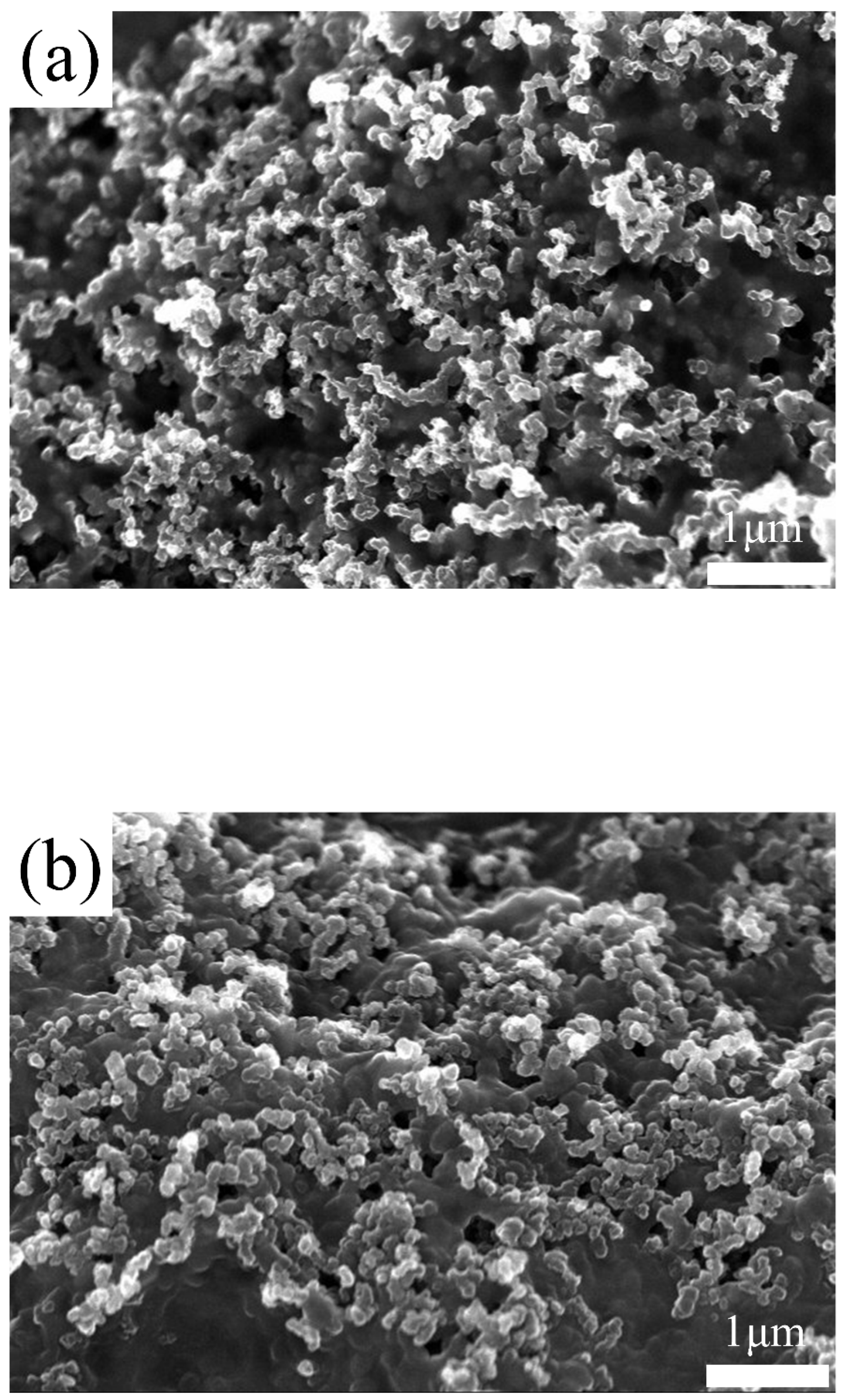
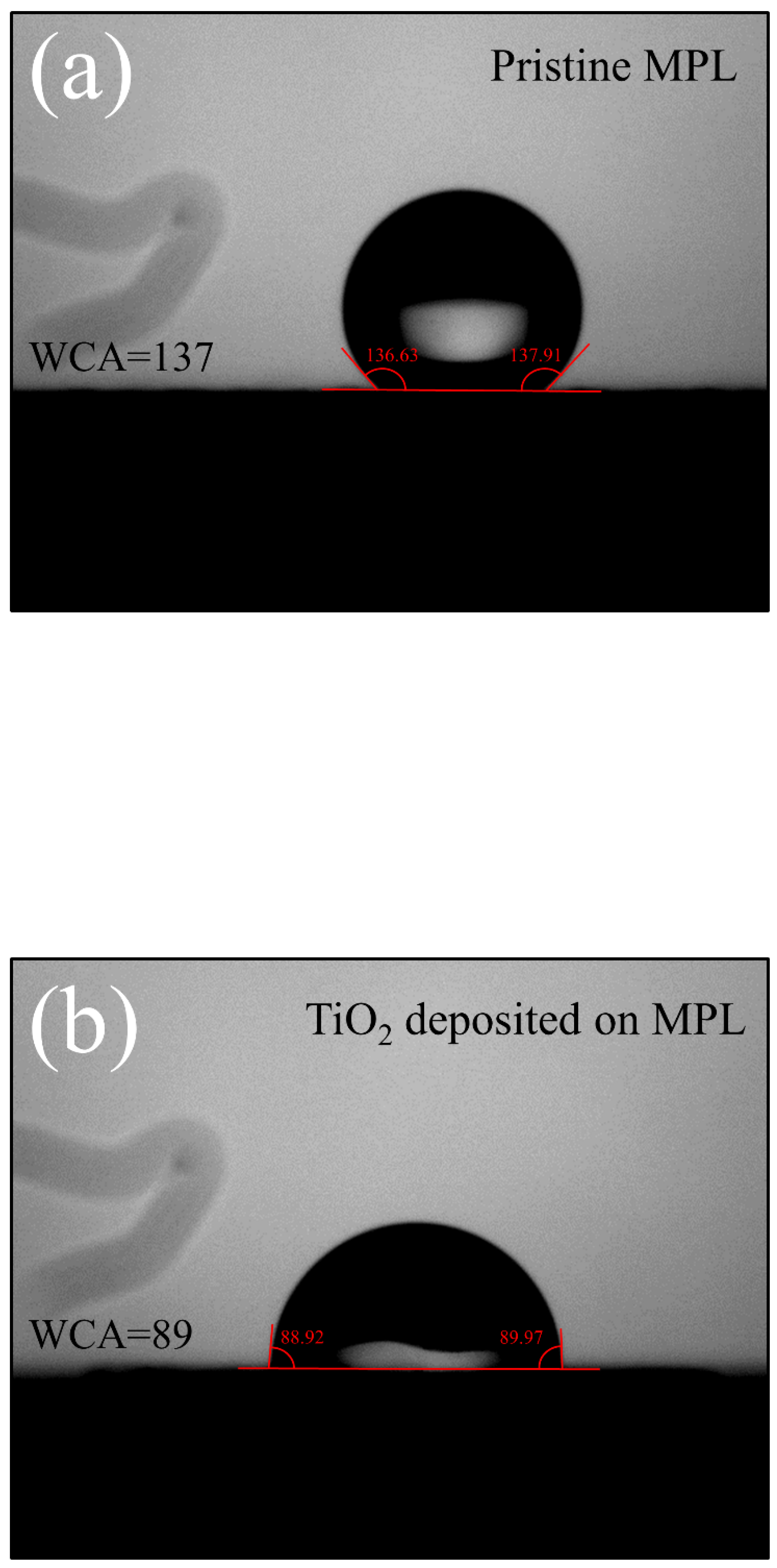
3.1. Analysis of TiO2 Deposited on MPL via Sputtering Process

TiO2 inherently possesses hydrophilic properties and contains oxygen vacancies [50]. These oxygen vacancies have a tendency to attract water molecules or retain free electrons on the surface or within the vacancies, contributing to the prevention of membrane dehydration and the enhancement of electronic conductivity [34,35]. First, the chemical composition of the TiO2-deposited MPL was analyzed using SEM-EDS. The results of the SEM-EDS analysis are presented in Table 1 and Figure 2. As shown in Table 1, the atomic percentage of Ti:O was measured as 1:1.2. This indicates that the TiO2 thin film has a relative deficiency of oxygen, suggesting the presence of numerous oxygen vacancies within the TiO2 film [51,52,53]. Figure 2 shows the distribution of Ti and O on the GDL surface analyzed through EDS mapping. The SEM image in Figure 2a illustrates the surface distribution of Ti and O particles on the MPL, revealing their uniform dispersion. This uniformity confirms the effectiveness of the sputtering process in achieving consistent and controlled deposition. Figure 3 presents the pristine GDL (MPL side) and the GDL with TiO2 deposited on the MPL side. The average pore size on the MPL side of a commercial GDL is approximately 7.0 µm, with a porosity of about 75–80%. In Figure 3a, it can be observed that the pristine GDL surface contains pores with diameters on the micrometer scale. These relatively large pores negatively affect the formation of thin films when using the sputtering process. The porosity and roughness of the substrate are widely known to hinder the formation of thin films during the sputtering process [54,55]. As shown in Figure 3b, although TiO2 was deposited onto the MPL, pores are still observed on the surface. The thickness of the TiO2 layer was controlled to be 30 nm, as calibrated using a Si wafer substrate. However, as shown in Figure 3a, the MPL, with micrometer-scale pores much larger than the nanometer-scale thin films, fails to form a uniform thin film. As shown in Figure 3b, TiO2 islands are not clearly visible on the rough surface of the MPL. This is likely because TiO2 exists in the form of nanoparticles, making it difficult to distinguish using SEM due to its nanometer-scale dimensions. To verify the presence of the sputter TiO2 on MPL, water contact analysis was conducted. Figure 4 presents the water contact angle measurement results for pristine MPL (a) and TiO2-deposited MPL (b). The contact angle of the pristine MPL was measured to be approximately 137°, indicating a hydrophobic surface. This high contact angle is attributed to the presence of PTFE (polytetrafluoroethylene) in the MPL of the PEMFC. PTFE facilitates water removal from the surface, enhancing the water management performance within the PEMFC [24]. In contrast, the TiO2-deposited MPL exhibited a significantly reduced contact angle of 89°, indicating a transition to a hydrophilic surface. The approximately 48° reduction in contact angle is primarily due to the intrinsic hydrophilicity of TiO2. Furthermore, the presence of oxygen vacancies further enhances this hydrophilicity by promoting water adsorption on the surface [48,50]. Oxygen vacancies play a critical role in the adsorption and retention of water molecules, thereby enhancing surface wettability [35]. By the water contact angle analysis, the hydrophilicity of the MPL was modified by adopting sputter TiO2. The pristine MPL facilitates water removal due to its hydrophobic nature, this characteristics can be detrimental in maintaining membrane hydration in dry environments [30]. In contrast, the TiO2-coated MPL exhibits a significantly reduced contact angle, strengthening moisture retention and supporting stable hydration. The inherent hydrophilicity of TiO2, along with its oxygen vacancies, promotes water adsorption and distribution, effectively preventing membrane dehydration under low-humidity conditions. These results highlight the potential of TiO2 to improve the overall performance and durability of PEMFCs, particularly under low-humidity conditions.

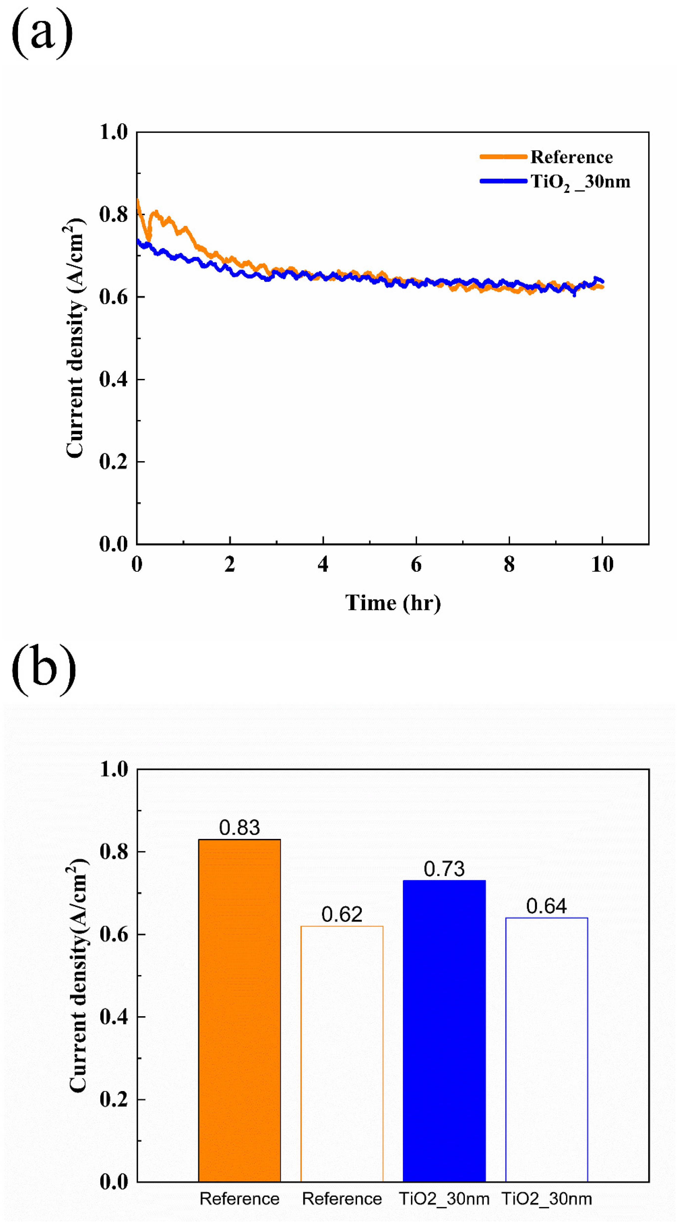
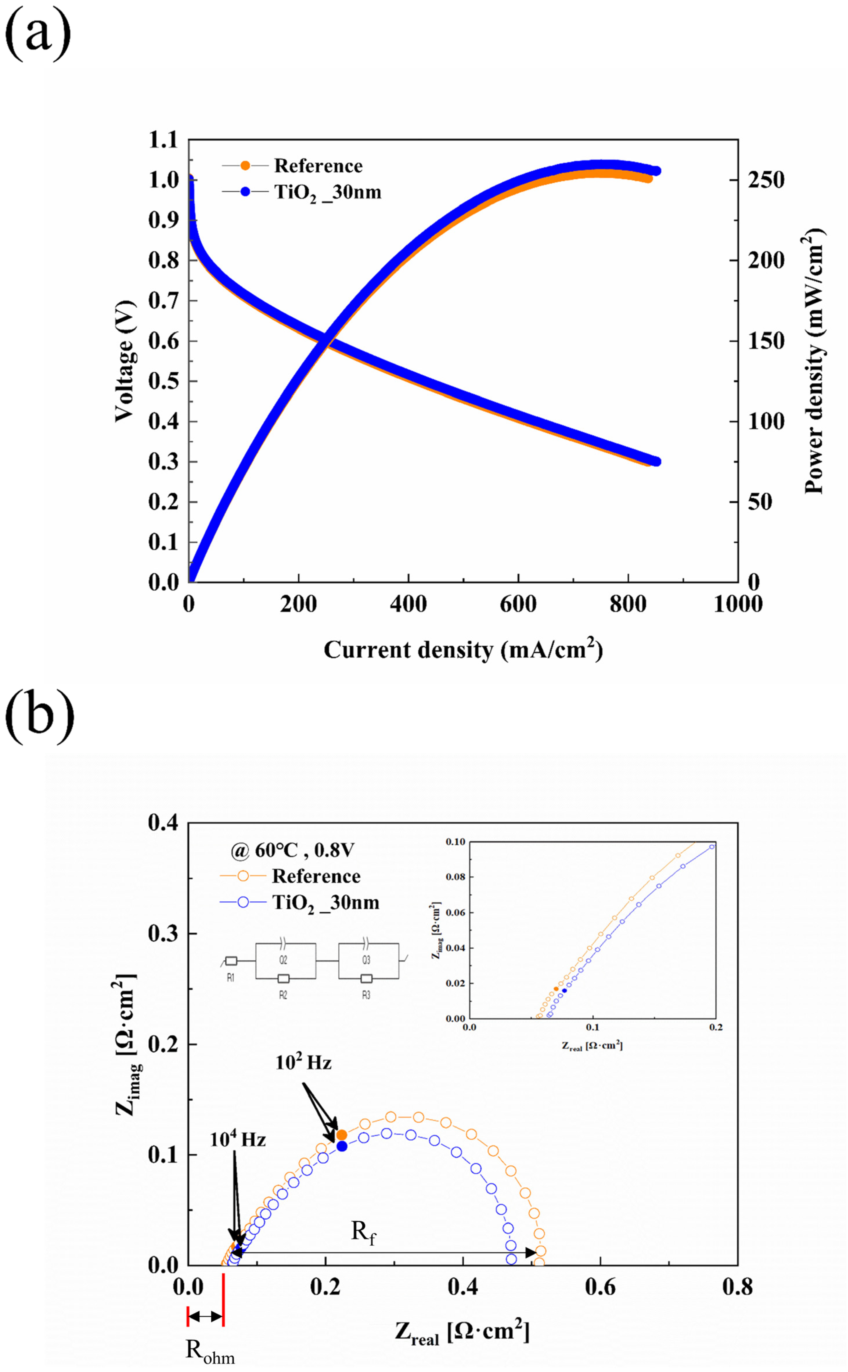
3.2. Fuel Cell Performance Evaluation

Figure 5 illustrates the initial electrochemical performance of the PEMFC before the long-term stability test. Before measuring its performance, the PEMFC underwent an activation process. As previously mentioned, the activation was conducted under fully humidified conditions (RH 100%). Subsequently, the humidity of the gases supplied to the anode and cathode was adjusted to RH 50% for performance evaluation. The electro-chemical performance of the fuel cell was evaluated under low-humidity conditions. Before the measurement, the PEMFC underwent an activation procedure under fully humidified conditions (RH 100%) to ensure sufficient membrane hydration and stabilize electrochemical reactions. The activation process involved operating the fuel cell under fully humidified conditions for a certain period until a stable performance was achieved. During this activation phase, the initial performance of the TiO2-coated MPL was lower than that of the uncoated MPL. This performance drop is attributed to the strong hydrophilicity of TiO2, which led to excessive water retention in the high-humidity environment, impeding gas diffusion and temporarily increasing mass transport resistance. However, once the PEMFC was transitioned to low-humidity conditions (RH 50%), the TiO2-coated GDL exhibited improved water retention, mitigating membrane dehydration and enhancing proton conductivity. These results align with previous studies indicating that hydrophilic surface modifications can lead to localized flooding under fully humidified conditions but provide significant advantages in maintaining water balance and stable performance under dry condition [56]. This dual behavior highlights the importance of optimizing TiO2 coating thickness and distribution to balance water retention and gas diffusion for long-term stability in PEMFC applications. Figure 5a shows the J-V-P curve when the gases supplied to the anode and cathode had a relative humidity (RH) of 50% after activation. Figure 5a shows the J-V-P curve when the gases supplied to the anode and cathode had a relative humidity (RH) of 50% after activation. The fuel cell with pristine MPL is referred to as the “Reference”, while the fuel cell with the TiO2-coated MPL is referred to as “TiO2_30 nm”. The performance of the reference fuel cell was 350.88 mW/cm2, whereas the initial performance of the TiO2_30 nm fuel cell was 294.66 mW/cm2, showing a 16.02% lower performance. The lower initial performance is attributed to the limited contribution of oxygen vacancies in TiO2 to the formation of electronic conduction pathways, which restricts electron transport. To further investigate this effect, EIS was performed to analyze changes in charge transport resistance and overall cell impedance. According to the studies by Pham et al. [35] and Sarkar et al. [52], oxygen vacancies can provide pathways for electron conduction; however, in the early stages, the number and distribution of oxygen vacancies might have been limited.
To evaluate the detailed behavior of the fuel cell, EIS measurements were conducted at 0.8 V, which is widely used in PEMFC studies for analyzing resistance components, particularly Faradaic resistance. The 0.8 V condition allows for a more accurate assessment of Faradaic resistance, which dominates the oxygen reduction reaction (ORR) kinetics in the cathode. Additionally, EIS data at 0.5 V is provided in the Supplementary Information for comparison (Figure S1), illustrating resistance variations at a lower operating voltage. The resistance in fuel cells is generally categorized into three types: faradaic resistance, ohmic resistance, and mass transport resistance. Ohmic resistance arises from ion transport through the electrolyte membrane and electrical conduction within the electrodes and bipolar plates. Faradaic resistance is associated with the electrochemical reactions occurring at the anode and cathode, particularly the sluggish oxygen reduction reaction (ORR) at the cathode. Mass transport resistance results from limitations in reactant gas diffusion and water management within the GDL and catalyst layer. Ohmic resistance can be identified from the Nyquist plot as the length from the origin to the intercept on the X-axis, which corresponds to the high-frequency region. Faradaic resistance is represented by the size of the semicircle drawn from the ohmic resistance on the Nyquist plot [1]. Figure 5b presents the EIS results of the fuel cells. The equivalent circuit model is also depicted in Figure 5b. As observed, the ohmic resistance and faradaic resistance of the TiO2_30 nm fuel cell are higher compared to those of the reference cell. At 0.8 V, the ohmic resistance and faradaic resistance of the reference cell were measured as 0.046 Ω·cm2 and 0.339 Ω·cm2, respectively. In contrast, the TiO2_30 nm fuel cell exhibited an ohmic resistance 0.058 Ω·cm2 (+26.09%) and a faradaic resistance of 0.372 Ω·cm2 (+9.73%). This increase is presumed to be due to the deposition of TiO2 on the MPL surface, which directly interacts with the catalyst layer. The increase in ohmic resistance and faradaic resistance after TiO2 deposition on the MPL is likely due to the insufficient formation of oxygen vacancies in the early stages, which limits electron transport. In the initial stages, the limited number and distribution of oxygen vacancies may result in inadequate conductive pathways, leading to increased ohmic and faradaic resistance.
Figure 6 presents the results of the constant voltage experiment, with Figure 6a showing the measurements over 10 h and Figure 6b summarizing the results in a bar graph. After measuring the performance of the activated fuel cell, long-term stability was evaluated at 0.4 V for 10 h. The initial current density of the reference fuel cell with the bare MPL was measured to be 0.83 A/cm2. The current density of the reference fuel cell decreased from 0.83 A/cm2 to 0.62 A/cm2 after 10 h, representing a 25.3% reduction. In comparison, the TiO2_30 nm fuel cell exhibited a decrease in current density from 0.73 A/cm2 to 0.64 A/cm2, corresponding to a 12.33% reduction. Following the durability assessment under constant voltage conditions, the performance of the fuel cells was re-measured and analyzed. The results are summarized in Figure 7, which presents both J-V-P curves and Nyquist plots. As shown in Figure 7a, the maximum power density of the reference fuel cell decreased from 350.88 mW/cm2 to 254.46 mW/cm2 after the 10 h constant voltage test, corresponding to a 27.48% reduction. In contrast, the TiO2_30 nm fuel cell exhibited a smaller reduction in power density, decreasing from 296.46 mW/cm2 to 259.81 mW/cm2 (12.36% reduction). Similarly, as shown in Figure 7b, the EIS results at 0.8 V revealed that the reference fuel cell experienced a 21.74% increase in ohmic resistance and a 50.74% increase in faradaic resistance. In comparison, the TiO2_30 nm fuel cell exhibited a more moderate 10.34% increase in ohmic resistance and a 26.34% increase in faradaic resistance. These results suggest that the fuel cell with TiO2-coated MPL demonstrated enhanced long-term stability under constant voltage operation. The superior durability of the TiO2_30 nm fuel cell can be attributed to multiple factors. First, while the presence of TiO2 initially increased ohmic resistance due to its intrinsic insulating properties and limited electron conduction pathways [35,44,46], the formation of oxygen vacancies over time provided alternative electron transport pathways, stabilizing resistance and mitigating excessive performance losses [35,37,52]. According to Pham et al. [35], oxygen vacancies within TiO2 facilitate electron conduction, and these pathways tend to stabilize with prolonged operation. This aligns with the observation that TiO2-coated MPL exhibited a lower increase in ohmic and faradaic resistance compared to the reference fuel cell. Beyond electron conduction effects, water management improvements also played a critical role in enhancing durability. While TiO2 coatings improve water retention under low-humidity conditions, previous studies have shown that they may contribute to excessive water accumulation under high-humidity conditions, potentially leading to flooding and performance degradation. While the hydrophilic nature of TiO2 improves water retention in dry conditions, its impact on drainage efficiency under humid conditions remains a challenge. Studies have suggested that optimizing hydrophilic–hydrophobic balance within MPL structures can promote capillary-driven water transport, preventing both dehydration and excessive flooding. Optimizing water removal strategies in high-humidity environments is essential to avoid excessive flooding and maintain stable performance at high power densities. Some studies have reported that ultra-thin hydrophilic coatings like TiO2 can facilitate a more uniform water distribution, which may reduce localized flooding while maintaining membrane hydration [56,57]. However, additional investigations are required to validate this effect under high-humidity, high-current-density conditions. This dual effect suggests that the application of TiO2-coated MPLs should be optimized depending on the operating humidity conditions of the fuel cell. In particular, at high current densities, excessive water accumulation can severely hinder gas diffusion and accelerate performance degradation, making drainage control an essential factor for large-scale PEMFC commercialization. However, this study primarily focuses on the performance of TiO2 coatings under low-humidity conditions, where water retention is a critical challenge. Future research will investigate the behavior of TiO2-coated MPLs under high-humidity conditions to fully understand their impact on PEMFC water management and performance stability.
TiO2 is well known for its hydrophilic nature and ability to adsorb water molecules due to the presence of oxygen vacancies [36,50,58]. As demonstrated by the contact angle measurements in Figure 4, TiO2 deposition significantly reduced the contact angle from 137° (pristine MPL) to 89°, indicating improved moisture retention and more uniform water distribution within the fuel cell. This enhanced hydrophilicity likely contributed to better membrane hydration, preventing excessive dry-out under low-humidity conditions (RH 50%) and ensuring stable proton conductivity [48,50]. Studies by Wang et al. [46] and McNeary et al. [44] further support this claim, demonstrating that TiO2 coatings contribute to improved moisture distribution, which enhances the overall water retention capability of the GDL. Furthermore, this improved water retention not only prevented excessive membrane dehydration but also influenced the electrochemical reaction environment. The presence of sufficient moisture in the catalyst layer and microporous layer likely facilitated proton conductivity and stabilized the oxygen reduction reaction (ORR), thereby reducing Faradaic resistance over time. As observed in Figure 7b, the TiO2-coated fuel cell exhibited a lower increase in Faradaic resistance compared to the reference fuel cell, suggesting that enhanced water management contributed to improved mass transport and reactant diffusion. Given that excessive water accumulation can also increase mass transport resistance by blocking gas diffusion pathways [20,45], the balanced hydrophilic-hydrophobic nature of the TiO2-coated MPL likely helped maintain efficient reactant gas diffusion while ensuring adequate hydration for stable electrochemical performance [45,46,52].

4. Conclusions

In this study, TiO2 was deposited onto the MPL using a sputtering method to enhance PEMFC performance under low-humidity conditions, and its electrochemical properties were evaluated. TiO2, with its inherent hydrophilicity and oxygen vacancies, improved interactions with water, contributing to enhanced membrane hydration and related performance improvements. However, during the initial stage after fuel cell activation, the TiO2 deposited on the MPL limited electron conductivity, leading to increased faradaic and ohmic losses. However, during the 10 h constant voltage test, an improvement in electron conductivity was inferred, suggesting that oxygen vacancies played a crucial role in providing electron transport pathways and enhancing electron conductivity. As a result, the performance degradation under low-humidity conditions was less pronounced compared to the non-deposited sample. These findings indicate that TiO2 deposition can effectively mitigate performance degradation in PEMFCs under low-humidity conditions. This demonstrates a significant contribution to the development of fuel cells capable of operating efficiently under low-humidity conditions. It reduces the need for external humidifiers in fuel cell systems, thereby lowering energy consumption and system complexity. Furthermore, it provides a technological foundation for various applications, including hydrogen fuel cell vehicles and distributed power systems.

Supplementary Materials

The following supporting information can be downloaded at: https://www.mdpi.com/article/10.3390/en18061525/s1, Figure S1. Electrochemical performance of PEMFCs after constant voltage experiments. (a) EIS results of fuel cells measure at 0.5 V before constant voltage evaluation. (b) EIS results of fuel cells measure at 0.5 V after constant voltage evaluation.

Author Contributions

Conceptualization, B.G.K., Y.R.K., K.W.H., S.K.K., D.K.S., J.W.J. and G.Y.C.; Methodology, B.G.K., K.W.H., S.K.K., H.M.L., J.W.J., D.G. and G.Y.C.; Software, B.G.K., Y.R.K., K.W.H. and J.W.J.; Validation, D.G. and G.Y.C.; Formal analysis, B.G.K., Y.R.K., K.W.H., S.K.K., H.M.L., D.K.S., D.Y.J., D.G. and G.Y.C.; Investigation, B.G.K., Y.R.K., K.W.H., H.M.L., D.K.S. and D.Y.J.; Resources, B.G.K., Y.R.K. and S.K.K.; Data curation, D.G. and G.Y.C.; Writing—original draft, B.G.K. and G.Y.C.; Writing—review & editing, B.G.K., D.G. and G.Y.C.; Visualization, B.G.K., D.Y.J., D.G. and G.Y.C.; Supervision, D.G. and G.Y.C. All authors have read and agreed to the published version of the manuscript.

Funding

This research received no external funding. The APC was fully waived under the ‘100% Discount Paper Invitation in 2025 [Energies] Special Issues: Sustainable Development of Fuel Cells and Hydrogen Technologies’.

Data Availability Statement

The original contributions presented in the study are included in the article and Supplementary Materials. Further inquiries can be directed to the corresponding author.

Conflicts of Interest

The authors declare no conflict of interest.

References

  1. Molaeimanesh, G.R.; Torabi, F. Fuel Cell Fundamentals. In Fuel Cell Modeling and Simulation; Elsevier: Amsterdam, The Netherlands, 2023; pp. 1–56. ISBN 9781119113805. [Google Scholar]
  2. Wu, D.; Peng, C.; Yin, C.; Tang, H. Review of System Integration and Control of Proton Exchange Membrane Fuel Cells; Springer: Berlin/Heidelberg, Germany, 2020; Volume 3, ISBN 0123456789. [Google Scholar]
  3. Yoo, H.J.; Cho, G.Y. Effects of Humidification with NaCl Solution Mist on Electrochemical Characteristics of Polymer Electrolyte Membrane Fuel Cells. Sustainability 2022, 14, 16242. [Google Scholar] [CrossRef]
  4. Hong, K.W.; Kwon, Y.R.; Song, D.K.; Jung, D.Y.; Kang, B.K.; Kwon, S.K. Fabrication and Characterization of Pt-Pr6O11 Nano Cathode Electrode for Polymer Electrolyte Membrane Fuel Cells via Co-Sputtering Method. Sustainability 2025, 17, 198. [Google Scholar] [CrossRef]
  5. Jang, G.E.; Cho, G.Y. Effects of Ag Current Collecting Layer Fabricated by Sputter for 3D-Printed Polymer Bipolar Plate of Ultra-Light Polymer Electrolyte Membrane Fuel Cells. Sustainability 2022, 14, 2997. [Google Scholar] [CrossRef]
  6. Yoo, H.J.; Cho, G.Y. Influences of Flow Channel on Electrochemical Characteristics of Polymer Electrolyte Fuel Cells Humidified with NaCl Contained H2O. Sustainability 2023, 15, 2415. [Google Scholar] [CrossRef]
  7. Jung, D.Y.; Song, D.K.; Kim, J.S.; Lee, S.H.; Min, G.W.; Son, J.H.; Cho, G.Y. Numerical Investigation of Effects of Obstacles in Flow Channels and Depth of Flow Channels for PEMFCs. Sustainability 2024, 16, 10144. [Google Scholar] [CrossRef]
  8. Dincer, I.; Acar, C. Review and Evaluation of Hydrogen Production Methods for Better Sustainability. Int. J. Hydrogen Energy 2014, 40, 11094–11111. [Google Scholar] [CrossRef]
  9. Nguyen, H.L.; Lee, S.M.; Yu, S. A Comprehensive Review of Degradation Prediction Methods for an Automotive Proton Exchange Membrane Fuel Cell. Energies 2023, 16, 4772. [Google Scholar] [CrossRef]
  10. Lei, H.; Xia, Y.; Hu, G. Effects of Inhomogeneous Gas Diffusion Layer Properties on the Transportation Phenomenon and Performances of Proton-Exchange Membrane Fuel Cells. ACS Omega 2024, 9, 9383–9395. [Google Scholar] [CrossRef]
  11. Xia, Z.; Wang, Y.; Ma, L.; Zhu, Y.; Li, Y.; Tao, J.; Tian, G. A Hybrid Prognostic Method for Proton-Exchange-Membrane Fuel Cell with Decomposition Forecasting Framework Based on AEKF and LSTM. Sensors 2023, 23, 166. [Google Scholar] [CrossRef]
  12. Borup, R.; Meyers, J.; Pivovar, B.S.; Kim, Y.S.; Mukundan, R.; Garland, N.; Myers, D.; Wilson, M.; Garzon, F.; Wood, D.; et al. Scientific Aspects of Polymer Electrolyte Fuel Cell Durability and Degradation. Chem. Rev. 2007, 107, 3904–3951. [Google Scholar] [CrossRef]
  13. Endoh, E.; Honmura, S.; Terazono, S.; Widjaja, H.; Takimoto, Y. Degradation Study of MEA for PEMFC under Low Humidity Conditions. Proc. Electrochem. Soc. 2004, 2004, 363–369. [Google Scholar] [CrossRef]
  14. Zaveri, J.C.; Dhanushkodi, S.R.; Kumar, C.R.; Taler, J.; Majdak, M.; Węglowski, B. Predicting the Performance of PEM Fuel Cells by Determining Dehydration or Flooding in the Cell Using Machine Learning Models. Energies 2023, 16, 6968. [Google Scholar] [CrossRef]
  15. Wang, X.R.; Ma, Y.; Gao, J.; Li, T.; Jiang, G.Z.; Sun, Z.Y. Review on Water Management Methods for Proton Exchange Membrane Fuel Cells. Int. J. Hydrogen Energy 2021, 46, 12206–12229. [Google Scholar] [CrossRef]
  16. Jienkulsawad, P.; Chen, Y.S.; Arpornwichanop, A. Modifying the Catalyst Layer Using Polyvinyl Alcohol for the Performance Improvement of Proton Exchange Membrane Fuel Cells under Low Humidity Operations. Polymers 2020, 12, 1865. [Google Scholar] [CrossRef]
  17. Bai, Q.; Hsieh, C.; Liu, Z.; Chen, Q.; Weng, F. Study on the Alleviation of Performance Degradation and Voltage Stability of PEMFC by Adding Silica Under Low-Temperature and Low-Humidity Conditions. Crystals 2024, 14, 1089. [Google Scholar] [CrossRef]
  18. Chun, J.H.; Park, K.T.; Jo, D.H.; Lee, J.Y.; Kim, S.G.; Park, S.H.; Lee, E.S.; Jyoung, J.Y.; Kim, S.H. Development of a Novel Hydrophobic/Hydrophilic Double Micro Porous Layer for Use in a Cathode Gas Diffusion Layer in PEMFC. Int. J. Hydrogen Energy 2011, 36, 8422–8428. [Google Scholar] [CrossRef]
  19. Dang, D.K.; Zhou, B. Enhanced Water Management in PEMFC Cathode Using Streamlined Baffles. J. Power Sources 2024, 623, 235475. [Google Scholar] [CrossRef]
  20. Zhou, K.; Li, T.; Han, Y.; Wang, J.; Chen, J.; Wang, K. Optimizing the Hydrophobicity of GDL to Improve the Fuel Cell Performance. RSC Adv. 2021, 11, 2010–2019. [Google Scholar] [CrossRef]
  21. Yang, D.; Fortin, P.; Garg, H.; Andersson, M. The Influence of Bipolar Plate Wettability on Performance and Durability of a Proton Exchange Membrane Fuel Cell. Int. J. Hydrogen Energy 2024, 95, 1284–1298. [Google Scholar] [CrossRef]
  22. Ji, M.; Wei, Z. A Review of Water Management in Polymer Electrolyte Membrane Fuel Cells. Energies 2009, 2, 1057–1106. [Google Scholar] [CrossRef]
  23. Pedapati, P.R.; Dhanushkodi, S.R.; Chidambaram, R.K.; Taler, D.; Sobota, T.; Taler, J. Design and Manufacturing Challenges in PEMFC Flow Fields—A Review. Energies 2024, 17, 3499. [Google Scholar] [CrossRef]
  24. Okonkwo, P.C.; Otor, C. A Review of Gas Diffusion Layer Properties and Water Management in Proton Exchange Membrane Fuel Cell System. Int. J. Energy Res. 2021, 45, 3780–3800. [Google Scholar] [CrossRef]
  25. Sun, X.; Xu, H.; Lu, L.; Xing, W.; Zhao, H. Preparing a Catalyst Layer in Magnetic Field to Improve the Performance of Proton Exchange Membrane Fuel Cells. J. Appl. Electrochem. 2014, 44, 1179–1184. [Google Scholar] [CrossRef]
  26. Wang, Y.; Liao, X.; Liu, G.; Xu, H.; Guan, C.; Wang, H.; Li, H.; He, W.; Qin, Y. Review of Flow Field Designs for Polymer Electrolyte Membrane Fuel Cells. Energies 2023, 16, 4207. [Google Scholar] [CrossRef]
  27. Isa, M.I.M.; Aziz, A.A. Optimized Flow Field Bipolar Plate Design in Proton Exchange Membrane Fuel Cell. In Proceedings of the 2012 10th IEEE International Conference on Semiconductor Electronics (ICSE), Kuala Lumpur, Malaysia, 19–21 September 2012; pp. 674–677. [Google Scholar] [CrossRef]
  28. Angayarkanni, R.; Ganesan, A.; Dhelipan, M.; Karthikeyan, S.; Mani, N.; Thiyagarajan, P. Self-Humidified Operation of a PEM Fuel Cell Using a Novel Silica Composite Coating Method. Int. J. Hydrogen Energy 2022, 47, 4827–4837. [Google Scholar] [CrossRef]
  29. Choi, I.; Lee, H.; Lee, K.G.; Ahn, S.H.; Lee, S.J.; Kim, H.J.; Lee, H.N.; Kwon, O.J. Characterization of Self-Humidifying Ability of SiO2-Supported Pt Catalyst under Low Humidity in PEMFC. Appl. Catal. B Environ. 2015, 168, 220–227. [Google Scholar] [CrossRef]
  30. Fang, S.Y.; Teoh, L.G.; Huang, R.H.; Hsueh, K.L.; Yang, K.H.; Chao, W.K.; Shieu, F.S. Enhancement of Proton Exchange Membrane Fuel Cell Performance by Titanium-Coated Anode Gas Diffusion Layer. Int. J. Hydrogen Energy 2014, 39, 21177–21184. [Google Scholar] [CrossRef]
  31. Su, H.; Xu, L.; Zhu, H.; Wu, Y.; Yang, L.; Liao, S.; Song, H.; Liang, Z.; Birss, V. Self-Humidification of a PEM Fuel Cell Using a Novel Pt/SiO2/C Anode Catalyst. Int. J. Hydrogen Energy 2010, 35, 7874–7880. [Google Scholar] [CrossRef]
  32. Le, T.M.H.; Chuchak, R.; Sairiam, S. Empowering TiO2–Coated PVDF Membranes Stability with Polyaniline and Polydopamine for Synergistic Separation and Photocatalytic Enhancement in Dye Wastewater Purification. Sci. Rep. 2024, 14, 15969. [Google Scholar] [CrossRef]
  33. Su, J.; Zou, X.; Chen, J.-S. Self-Modification of Titanium Dioxide Materials by Ti3+ and/or Oxygen Vacancies: New Insights into Defect Chemistry of Metal Oxides. SC Adv. 2014, 4, 13979–13988. [Google Scholar] [CrossRef]
  34. Pham, H.H.; Wang, L.W. Oxygen Vacancy and Hole Conduction in Amorphous TiO2. Phys. Chem. Chem. Phys. 2015, 17, 541–550. [Google Scholar] [CrossRef]
  35. Elahifard, M.; Sadrian, M.R.; Mirzanejad, A.; Behjatmanesh-Ardakani, R.; Ahmadvand, S. Dispersion of Defects in TiO2 Semiconductor: Oxygen Vacancies in the Bulk and Surface of Rutile and Anatase. Catalysts 2020, 10, 397. [Google Scholar] [CrossRef]
  36. Nadeem, I.M.; Harrison, G.T.; Wilson, A.; Pang, C.L.; Zegenhagen, J.; Thornton, G. Bridging Hydroxyls on Anatase TiO2(101) by Water Dissociation in Oxygen Vacancies. J. Phys. Chem. B 2018, 122, 834–839. [Google Scholar] [CrossRef] [PubMed]
  37. Zhang, W.; Chen, Y.; Jin, Y.; Liu, H.; Ma, Q.; Xu, Q.; Su, H. TiO2 Nanolayer Coated Carbon Support for Highly Durable High-Temperature Polymer Electrolyte Membrane Fuel Cell Cathode. Int. J. Hydrogen Energy 2024, 65, 829–836. [Google Scholar] [CrossRef]
  38. Parsons, G.N.; George, S.M.; Knez, M. Progress and Future Directions for Atomic Layer Deposition and ALD-Based Chemistry. MRS Bull. 2011, 36, 865–871. [Google Scholar] [CrossRef]
  39. Oviroh, P.O.; Akbarzadeh, R.; Pan, D.; Coetzee, R.A.M.; Jen, T.C. New Development of Atomic Layer Deposition: Processes, Methods and Applications. Sci. Technol. Adv. Mater. 2019, 20, 465–496. [Google Scholar] [CrossRef]
  40. Poddighe, M.; Innocenzi, P. Hydrophobic Thin Films from Sol–Gel Processing: A Critical Review. Materials 2021, 14, 6799. [Google Scholar] [CrossRef]
  41. Pandey, S.; Mishra, S.B. Sol-Gel Derived Organic-Inorganic Hybrid Materials: Synthesis, Characterizations and Applications. J. Sol-Gel Sci. Technol. 2011, 59, 73–94. [Google Scholar] [CrossRef]
  42. Rafieian, D.; Ogieglo, W.; Savenije, T.; Lammertink, R.G.H. Controlled Formation of Anatase and Rutile TiO2 Thin Films by Reactive Magnetron Sputtering. AIP Adv. 2015, 5, 097168. [Google Scholar] [CrossRef]
  43. Simionescu, O.G.; Romanitan, C.; Tutunaru, O.; Ion, V.; Buiu, O.; Avram, A. RF Magnetron Sputtering Deposition of TiO2 Thin Films in a Small Continuous Oxygen Flow Rate. Coatings 2019, 9, 442. [Google Scholar] [CrossRef]
  44. McNeary, W.W.; Linico, A.E.; Ngo, C.; van Rooij, S.; Haussener, S.; Maguire, M.E.; Pylypenko, S.; Weimer, A.W. Atomic Layer Deposition of TiO2 for Stabilization of Pt Nanoparticle Oxygen Reduction Reaction Catalysts. J. Appl. Electrochem. 2018, 48, 973–984. [Google Scholar] [CrossRef]
  45. Kitahara, T.; Nakajima, H.; Inamoto, M.; Morishita, M. Novel Hydrophilic and Hydrophobic Double Microporous Layer Coated Gas Diffusion Layer to Enhance Performance of Polymer Electrolyte Fuel Cells under Both Low and High Humidity. J. Power Sources 2013, 234, 129–138. [Google Scholar] [CrossRef]
  46. Wang, Y.; Zhang, W.; Liu, H.; Xu, Q.; Khotseng, L.; Cheng, Y.; Su, H. Cultivating Titanium Dioxide Nanoarrays on Gas Diffusion Layer for Advancing Self-Humidifying Proton Exchange Membrane Fuel Cell. Fuel 2024, 366, 131322. [Google Scholar] [CrossRef]
  47. Mirshekari, G.R.; Shirvanian, A.P. Electrochemical Behavior of Titanium Oxide Nanoparticles for Oxygen Reduction Reaction Environment in PEM Fuel Cells. Mater. Today Energy 2018, 9, 235–239. [Google Scholar] [CrossRef]
  48. Choun, M.; Chung, S.; Jeon, H.; Uhm, S.; Lee, J. Atomic-Layer-Deposited TiO2 on Cathode Gas Diffusion Layer for Low Humidity Operation in Hydrogen Fuel Cells. Electrochem. Commun. 2012, 24, 108–111. [Google Scholar] [CrossRef]
  49. Ng, S.; Sopha, H.; Zazpe, R.; Spotz, Z.; Bijalwan, V.; Dvorak, F.; Hromadko, L.; Prikryl, J.; Macak, J.M. TiO2 ALD Coating of Amorphous TiO2 Nanotube Layers: Inhibition of the Structural and Morphological Changes Due to Water Annealing. Front. Chem. 2019, 7, 38. [Google Scholar] [CrossRef] [PubMed]
  50. Saini, C.P.; Barman, A.; Das, D.; Satpati, B.; Bhattacharyya, S.R.; Kanjilal, D.; Ponomaryov, A.; Zvyagin, S.; Kanjilal, A. Role of Oxygen Vacancy on the Hydrophobic Behavior of TiO2 Nanorods on Chemically Etched Si Pyramids. J. Phys. Chem. C 2017, 121, 278–283. [Google Scholar] [CrossRef]
  51. Arenas-Hernandez, A.; Zuñiga Islas, C.; Moreno, M.; Calleja Arriaga, W.; Mendoza-Cervantes, J.C.; Carlos, N.; Ascencio-Hurtado, C.R.; Heredia Jiménez, A. Study of Oxygen Vacancies in TiO2 Nanostructures and Their Relationship with Photocatalytic Activity. Appl. Sci. 2022, 12, 3690. [Google Scholar] [CrossRef]
  52. Sarkar, A.; Khan, G.G. The Formation and Detection Techniques of Oxygen Vacancies in Titanium Oxide-Based Nanostructures. Nanoscale 2019, 11, 3414–3444. [Google Scholar] [CrossRef]
  53. Pan, X.; Yang, M.Q.; Fu, X.; Zhang, N.; Xu, Y.J. Defective TiO2 with Oxygen Vacancies: Synthesis, Properties and Photocatalytic Applications. Nanoscale 2013, 5, 3601–3614. [Google Scholar] [CrossRef]
  54. Reis, F.D.A.A.; Mallio, D.O.; Galindo, J.L.; Huertas, R. Scaling of Roughness and Porosity in Thin Film Deposition with Mixed Transport Mechanisms and Adsorption Barriers. Phys. Rev. E 2020, 102, 042802. [Google Scholar] [CrossRef] [PubMed]
  55. Sievers, G.; Vidakovic-Koch, T.; Walter, C.; Steffen, F.; Jakubith, S.; Kruth, A.; Hermsdorf, D.; Sundmacher, K.; Brüser, V. Ultra-Low Loading Pt-Sputtered Gas Diffusion Electrodes for Oxygen Reduction Reaction. J. Appl. Electrochem. 2018, 48, 221–232. [Google Scholar] [CrossRef]
  56. Hou, S.; Ye, Y.; Liao, S.; Ren, J.; Wang, H.; Yang, P.; Du, K.; Li, J.; Peng, H. Enhanced Low-Humidity Performance in a Proton Exchange Membrane Fuel Cell by Developing a Novel Hydrophilic Gas Diffusion Layer. Int. J. Hydrogen Energy 2020, 45, 937–944. [Google Scholar] [CrossRef]
  57. Mohamed Zahidi, M.; Mamat, M.H.; Malek, M.F.; Yaakob, M.K.; Ahmad, M.K.; Abu Bakar, S.; Mohamed, A.; Subki, A.S.R.; Mahmood, M.R. Evaluating Different TiO2 Nanoflower-Based Composites for Humidity Detection. Sensors 2022, 22, 5794. [Google Scholar] [CrossRef]
  58. Wang, Z.; Qu, L.; Zeng, Y.; Guo, X.; Shao, Z.; Yi, B. Investigation of Water Transport in Fuel Cells Using Water Transport Plates and Solid Plates. RSC Adv. 2018, 8, 1503–1510. [Google Scholar] [CrossRef]
Figure 1. Schematics of experiments (a) sputter process chamber, (b) PEMFC components (left), sputter-deposited TiO2 on MPL (right).
Energies 18 01525 g001
Figure 2. SEM-EDS mapping results of TiO2 deposited MPL. (a) SEM image, (b) Ti distribution (left), and O distribution (right).
Energies 18 01525 g002
Figure 3. SEM results. (a) Pristine MPL and (b) TiO2 deposited MPL.
Energies 18 01525 g003
Figure 4. Results of water contact angle measurements. (a) Pristine MPL and (b) TiO2 deposited MPL.
Energies 18 01525 g004
Figure 5. Electrochemical performance of PEMFCs before constant voltage experiments. (a) J-V-P curves of PEMFCs before constant voltage experiment. (b) EIS results of fuel cells measure at 0.8 V before constant voltage evaluation.
Energies 18 01525 g005
Figure 6. Results of constant voltage evaluation at 0.4 V. (a) Current—time curve of fuel cells and (b) summary of constant voltage experiments.
Energies 18 01525 g006
Figure 7. Electrochemical performance of PEMFCs after constant voltage experiments. (a) J-V-P curves of PEMFCs after constant voltage experiment. (b) EIS results of fuel cells measure at 0.8 V after constant voltage evaluation.
Energies 18 01525 g007
Table 1. SEM-EDS results of TiO2 on the MPL.
ElementMass Norm. [%]Atomic [%]Error [%]
C1.233.430.46
O23.5649.504.57
Si2.933.510.28
Ti58.7441.232.78
Pt13.542.330.74
100.00100.00
Disclaimer/Publisher’s Note: The statements, opinions and data contained in all publications are solely those of the individual author(s) and contributor(s) and not of MDPI and/or the editor(s). MDPI and/or the editor(s) disclaim responsibility for any injury to people or property resulting from any ideas, methods, instructions or products referred to in the content.

