1. Introduction
A large field of application for photovoltaics (PVs), which is currently hardly served, is the self-sufficient energy supply of electronic components and small electrical devices in the consumer sector [
1,
2,
3]. For this field of application, corresponding photovoltaic systems should be very light, highly stable, and 3D flexible, that means bendable in all directions. The ability to integrate it into clothing would also be advantageous. In order to keep manufacturing costs low and not to require a separate production line for each power range, the solar modules should also be able to be manufactured in a large-area and subsequently to be cut into the required shape and size. Solar fabrics based on photovoltaic active thin film systems on the surface of textiles can meet these requirements in an ideal way. The applications of these extend from the energy supply of electronic sensor systems in clothing, e.g., for monitoring body functions in the medical, wellness, or sports sectors, to the supply of electronic devices such as smartphones in clothing, or in outdoor use [
4]. In addition, the field of applications for large-area solar fabrics can be expanded to integration into buildings (Bi-PV), as truck tarpaulins, or for agricultural areas (Agri-PV) [
5]. Solar cells on textiles could also act as optical sensors for applications in personal protective equipment (PPE) and clothing [
6].
However, no products with solar cells directly fabricated on fabrics are currently available on the market. Instead, flexible solar cells on foils are offered. However, these have limited flexibility and drapability as required for use in clothing. Their application areas here are lightweight solar modules for roof and wall integration of buildings [
5,
7,
8]. For such applications, the rolling up and down of the modules is an advantage, apart from the low weight. Another consumer niche is solar backpacks with plug-in mini modules [
9].
Currently worldwide research is being performed on various types of thin film solar cells on textiles. On the one hand, the solar cell layers are applied to single textile fibers and used individually or processed into fabrics [
4,
10,
11,
12,
13]. On the other hand, the solar cell layer systems are directly deposited on the surfaces of textiles [
4,
10,
14,
15]. In the case of solar cells on single fibers, only extremely low outputs are achieved. The problem of realizing flat and large-area fabrics from them is the mechanical stress on the PV layers during the weaving process, which often leads to local damage. An overview of the results on the different textile solar cells are given in [
4,
14,
15]. Particularly advantageous for solar fabrics are solar cells based on hydrogenated amorphous silicon (a-Si:H) [
16,
17,
18]. These have long-term stability without the need for complex encapsulation, unlike organic solar cells (OPV) [
4,
19,
20,
21,
22,
23] or dye-sensitized solar cells (DSSCs) [
24,
25,
26,
27,
28,
29,
30]. Amorphous silicon can be deposited at significantly lower temperatures compared to copper indium gallium diselenide (CIGS) solar cell systems. These require a textile coating that is stable at high temperatures, resulting in a large loss of flexibility and thus textile properties [
31]. In addition, a-Si:H solar cells are harmless to health for use in clothing, unlike perovskite (CH
3NH
3PbI
3) solar cells [
4,
14,
32,
33], which are not suitable for use in immediate human environments due to the presence of toxic lead.
The focus of this work is the research, development, fabrication, and characterization of 3D flexible solar fabrics based on a-Si:H solar cells. The aim is to significantly increase the efficiency that has already been published for this type of solar cell [
18] in order to enable economic production in the future. Up to now, photovoltaic efficiencies of 1.4% and pseudo efficiencies of 2.1% have been reported [
18]. Here, we show the way to 3.9% and 7.6%, respectively. A broad review of the efficiencies achieved by various technologies on textiles is available in the literature [
4].
The challenge is to find a suitable textile substrate that has the temperature and vacuum stability required for the coating process and is adapted to the thermal expansion properties of the solar cell materials. Furthermore, the materials and the layer structure of the solar cells as well as the manufacturing processes have to be adapted to the surface topography of the textile substrate. A design was developed for the arrangement and electrical interconnection of the solar cells on the fabric. This will allow modules with the desired electrical output and geometry to be produced in future production by cutting them out of a large-area solar fabric.
2. Material and Methods
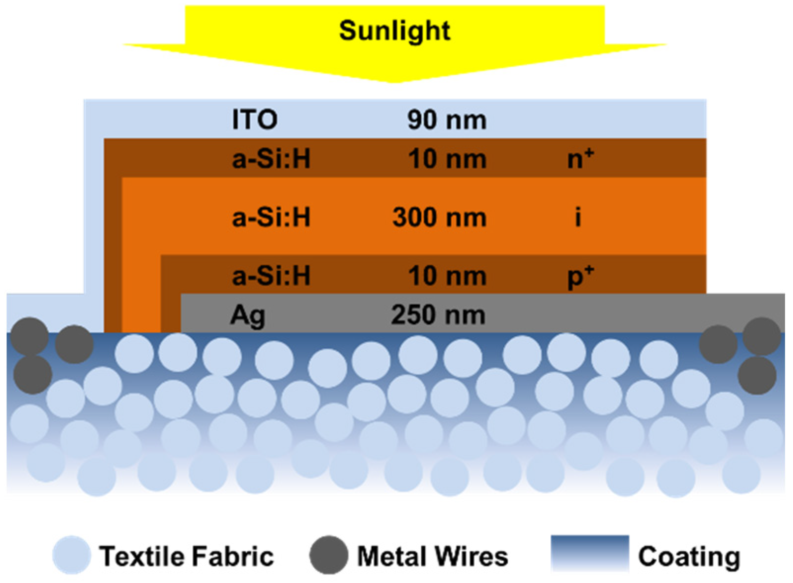
The solar fabrics are realized by the deposition of the following layers on top of a polytetrafluoroethylene (PTFE)-coated fabric with interwoven metal wires. On the bottom, a silver (Ag) electrode is used, then hydrogenated amorphous silicon (a-Si:H) with a highly p-type (p
+), intrinsic (i), and n-type (n
+) doping profile is deposited and indium tin oxide (ITO) as a transparent conductive oxide (TCO) is used as the top electrode. The scheme of the resulting amorphous silicon thin film solar cells on textiles is shown in
Figure 1.
2.1. Textile Substrate
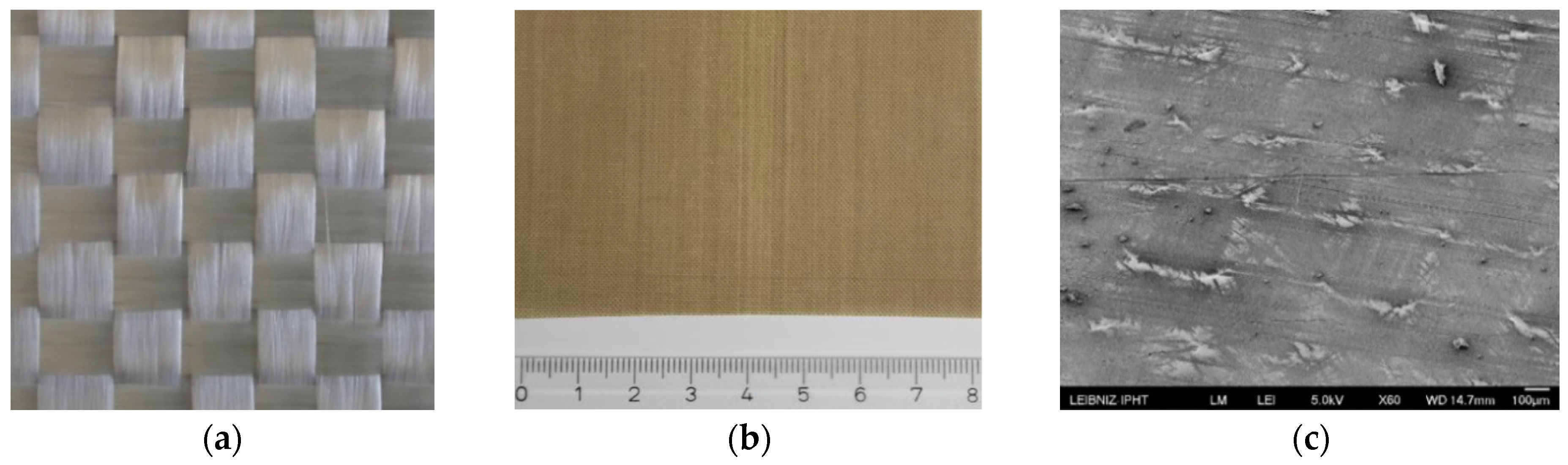
The textile substrate used for the solar cell layer system is a glass fiber fabric, as shown, for example, in the photograph of
Figure 2a. The glass fiber fabric is coated by polytetrafluoroethylene (PTFE) with thicknesses available between 70 µm and 250 µm. A photograph is given in
Figure 2b and an SEM image of the surface is shown in
Figure 2c. From the SEM investigation, it is seen that the PTFE coating results in a closed surface without holes, voids, or steep edges, which is required for short-circuit-free solar cells. The pre-treatment experiments showed that the fabric remains stable in the vacuum at 1 mbar for at least 30 min at a temperature of 230 °C as needed for the layer deposition. In addition, the thermal expansion of the glass fiber fabric with PTFE coating matches better to the silicon layer with 4 × 10
−6 K
−1 and the silver layer with 19 × 10
−6 K
−1, compared to polymer-based textiles and fabrics so that the solar cell layer system can be applied without cracking. Another advantage of the PTFE-coated glass fiber fabrics is the durability across various environmental conditions.
2.2. Deposition of Thin Film Solar Cell
The fabrication for the solar fabric as shown in
Figure 1 starts with a 250–300 nm thin silver layer deposited by electron beam evaporation (EBE) at 200 °C heater temperature. The deposition of the photovoltaic active a-Si:H layer system is carried out by plasma-enhanced chemical vapor deposition (PECVD). The heater temperature was varied between 180 °C and 225 °C. The first a-Si:H layer is highly p-doped with thicknesses varied from 10 nm to 30 nm. This is followed by a 300 nm to 500 nm thin intrinsic a-Si:H layer. The layer system is completed by a 10 nm to 30 nm thin highly n-doped a-Si:H. The p
+ or n
+ doping was performed with 3% diborane or phosphine in silane, respectively. The resulting dopant concentration is about 10
19 cm
−3 in both cases. Finally, an indium tin oxide (ITO) layer of 90 nm or 200 nm as a transparent top electrode was deposited by DC magnetron sputtering in rotating mode using 5 × 10
−3 mbar argon pressure and 70 W sputtering power. The thicknesses of all layers were evaluated by co-deposition on a flat substrate and measured using a stylus profilometer. In this way, a homogeneous crack-free solar cell layer system can be applied to the flexible PTFE-coated glass fiber fabric (see
Figure S1 in the Supplementary Materials).
2.3. Solar Fabric Design
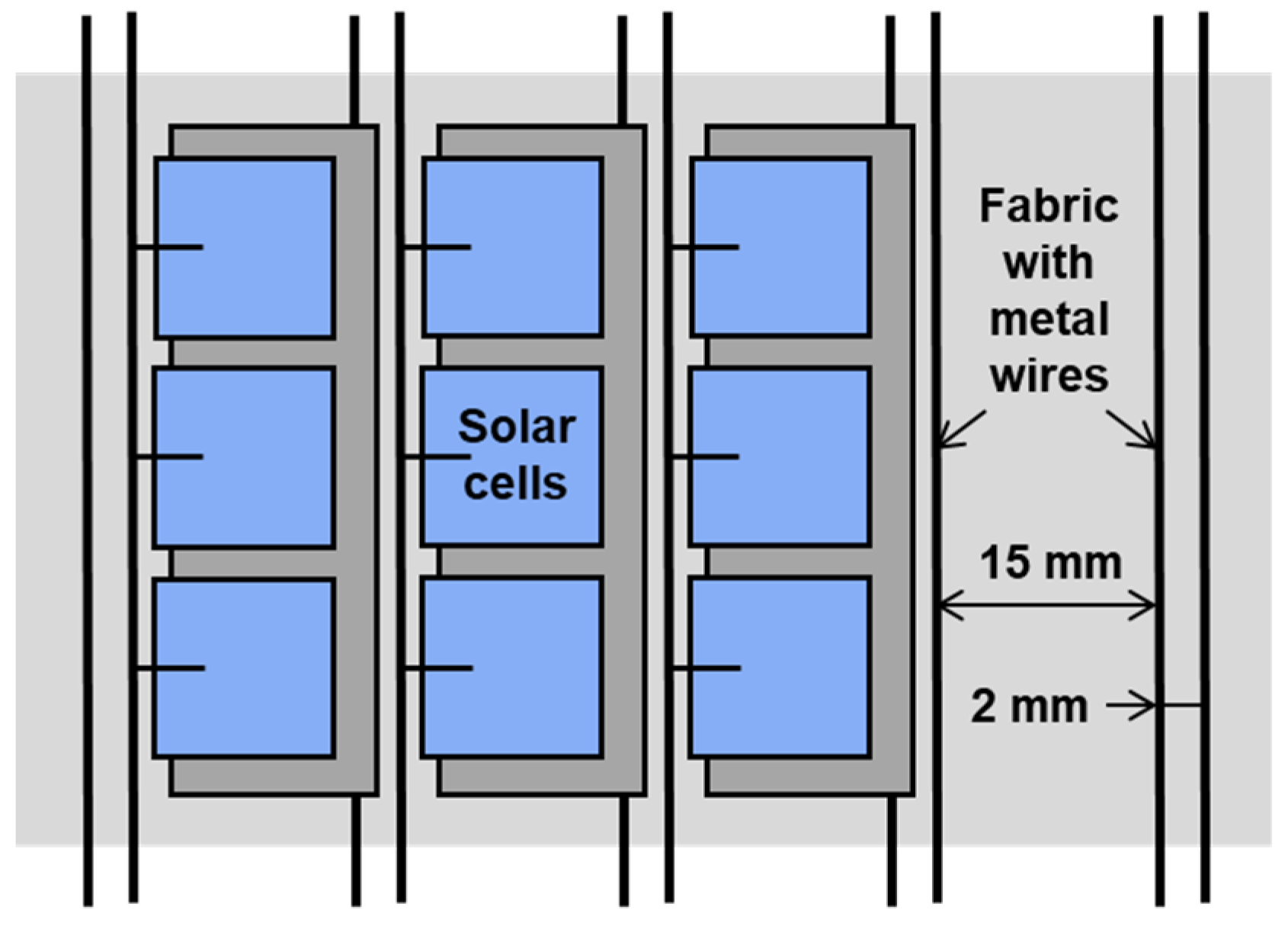
The long-term goal of our work is a solar fabric that makes it possible to produce modules with desired electrical performance and geometry by cutting them out of a large-area solar fabric. The design concept and the first steps to realize this solar fabric is shown in
Figure 3. As shown in the scheme, the fabric should have metal wires woven into periodic intervals of 2 mm and 15 mm. The solar cells of 1 cm by 1 cm are arranged between the metal filaments, with contact of the bottom and top electrode to one wire each. The solar cells, which are arranged in a row longitudinally between two contact wires, are consequently connected in parallel. So, the generated electrical currents are added. The solar cells, arranged in a row perpendicular to the wires, are connected in a series. This leads to the addition of the generated voltages. By cutting parallel and perpendicular to the contact wires, solar modules with a desired J–V characteristics and size can be processed. For this, only the protruding wires at the edge need to be connected as desired. The textile industry offers corresponding fabrics with interwoven conductive filaments (see
Figure S2a,b in the Supplementary Materials).
2.4. Characterization
The current–voltage (J–V) measurements of the solar cells were carried out with a solar simulator (PET SS-80A, Photo Emission Tech Inc., Moorpark, CA, USA) under irradiation of 1000 W/m2 with the air mass 1.5 global (AM 1.5g) spectra. The pseudo J–V curves and parameters were determined from suns-Voc measurements (Sinton Suns-Voc-150, Sinton Instruments, Boulder, CO, USA) to negate the influence of the series resistance. This is a common method to quickly determine the quality of the solar cell layer even without or before high quality electrical contracting. A spectrometer (Perkin-Elmer Lambda 900, PerkinElmer Inc., Waltham, MA, USA) with an integrated scattered light sphere was used for optical characterization of the solar cell layer system. The surface of the PTFE-coated glass fiber fabric was analyzed by scanning electron microscopy (SEM) with high resolution (FE-SEM JSM-6700F; JEOL Ltd., Tokyo, Japan).
3. Results and Discussion
Following the concept for interconnection presented in
Section 2.3, solar cell arrays consisting of eight 1 by 1 cm
2 solar cells and nine smaller test solar cells were deposited on 5 by 5 cm
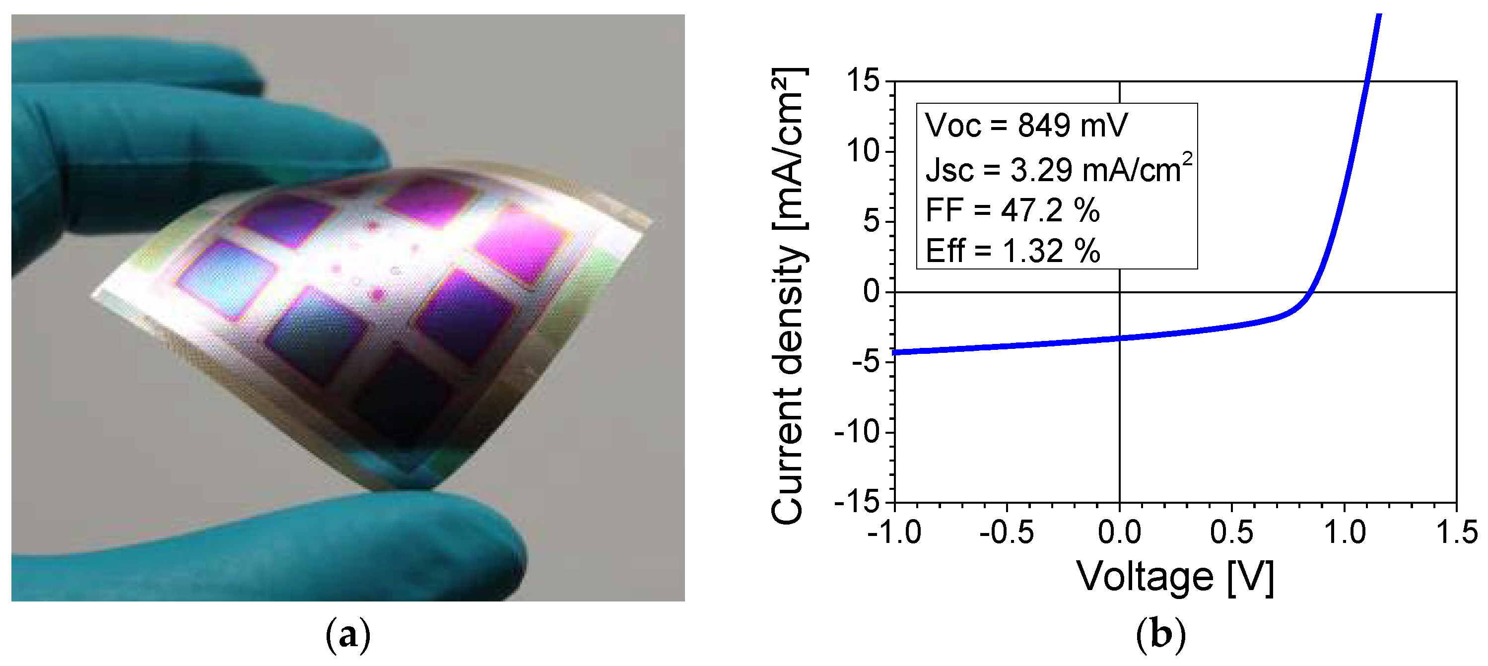
2 and 70 µm thick PTFE-coated glass fiber fabric, as shown in
Figure 4a. In accordance with the layer system shown in
Figure 1, at first, a 250 nm thin silver layer was deposited on a (nearly) full area apart from the sample holder. Then, the a-Si:H layer system with the doping profile (10 nm of p
+/300 nm of i/10 nm of n
+) was deposited and structured by a 4 by 4 cm
2 shadow masks. The substrate temperature within the PECVD was 180 °C. Finally, the 90 nm thin ITO layer was deposited and structured by shadow mask to realize the solar cell areas.
The solar cells with this specified layer system were optoelectronically analyzed. The current–voltage measurements with the applied contact pins under the solar simulator resulted in the J–V curve shown in
Figure 4b. An open-circuit voltage of nearly 849 mV demonstrates shunt-free contact layers, even on flexible and non-planar textile substrates. The short-circuit current density is very low with only 3.29 mA/cm
2 and must be optimized as given below. These solar cells had a maximum efficiency of 1.32% with a fill factor of 47.2%.
Various optimization steps were carried out to improve the initial efficiency. To reduce the contact resistance between Ag and a-Si:H, the solar cell layer system was supplemented with an aluminum-doped zinc oxide (Al:ZnO) layer. The 200 nm thin Al:ZnO was deposited by atomic layer deposition (ALD) on top of the silver layer. Furthermore, the substrate temperature during the a-Si:H deposition was increased from 180 °C to 225 °C, which reduces the defect density in the absorber. Additionally, the thickness of the intrinsic a-Si:H layer was increased from 300 nm to 500 nm to enhance the optical absorption. Also, the thickness of the n
+ doped layer was increased from 10 nm to 20 nm, as this is expected to reduce the density of micro-holes in this layer. With regard to the thickness of the ITO layer, a compromise had to be found between the low optical absorption and high electrical conductivity. A layer thickness of 200 nm was determined to be optimal and homogenous [
34].
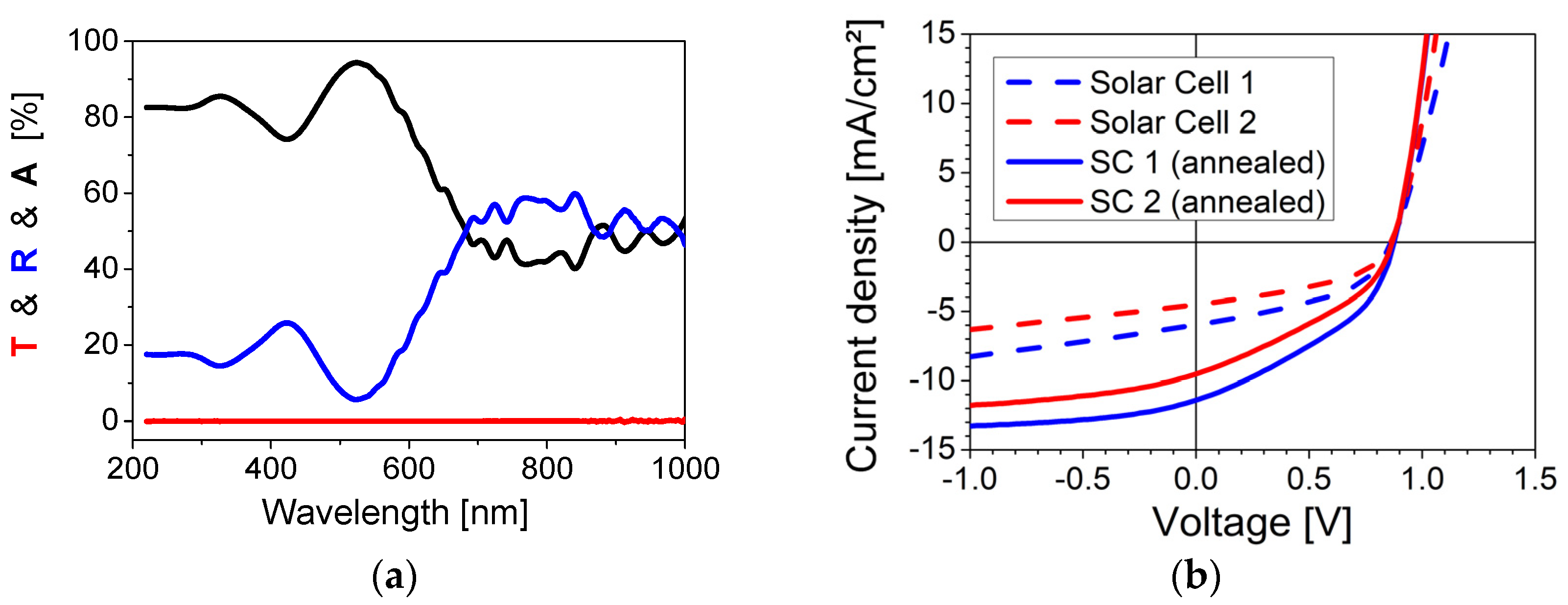
The solar cell layer system optimized in this way was optically characterized in the UV-VIS-NIR spectral region, as shown in
Figure 5a. The measured transmission (T, red) and reflection (R, blue) values are given in the same way as the calculated (
T +
R +
A = 1) absorption values (A, black). For the maximum of the sunlight spectrum at about 550 nm wavelength, more than 90% is absorbed in the solar cell layer system.
The mentioned improvements lead to solar cells with J–V characteristics shown in both dashed lines in
Figure 5b. The open-circuit voltages are 860–863 mV and the short-circuit current densities are 4.9–6.0 mA/cm
2. These solar cells had efficiencies of 1.9–2.3% with fill factors of 44.5–45.2%.
Furthermore, an additional annealing step at 200 °C for 60 min resulted in a further improvement of the solar cell parameters especially for the short-circuit current density. Presumably, this results in a reduction in the layer stresses as well as in the defect healing at the interfaces due to hydrogen passivation. This effect on the J–V curve is demonstrated in
Figure 5b for two different solar cells. The annealing step increases the short-circuit current density from 6.0 mA/cm
2 to 11.4 mA/cm
2 for the first solar cell (blue). In the second case (red), it is increased from 4.9 mA/cm
2 to 9.5 mA/cm
2. This suggests a reduced recombination of the generated electron hole pairs.
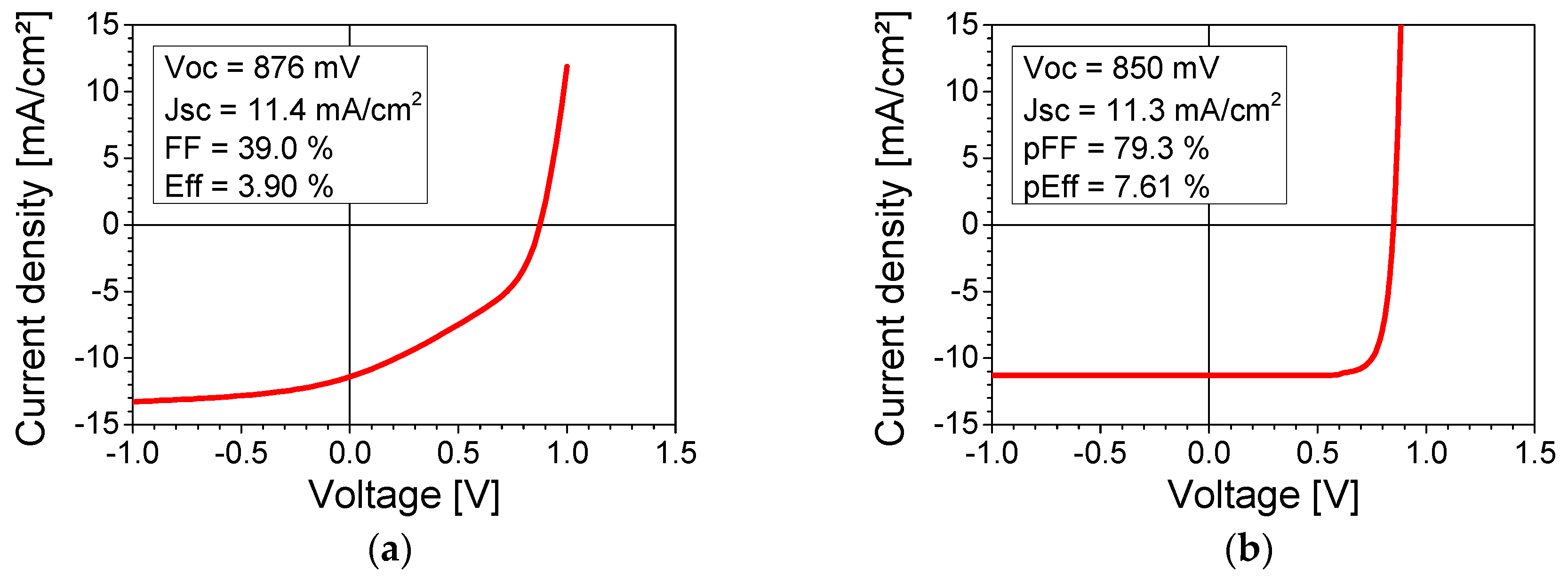
With the help of the optimization of the layer system and the additional annealing step as described above, it was possible to realize a solar cell with an efficiency of 3.9%. The corresponding J–V curve under the solar simulator with AM1.5g is given in
Figure 6a. The open-circuit voltage could be slightly improved to 876 mV. A significant increase is observed in the short-circuit current density to 11.4 mA/cm
2. A challenge and limit is the low fill factor of only 39.0% caused by the high contact resistance.
A suns-V
oc measurement was carried out in order to validate and demonstrate the potential of the solar fabrics. The determined pseudo J–V curve and parameters in
Figure 6b negate the influence of the series resistance. In this case, the results are a high pseudo fill factor of 79.3%. With similar V
oc and J
sc, a pseudo efficiency of 7.6% is achieved. These values show the potential of the textile solar cells with low-loss ohmic contacting.
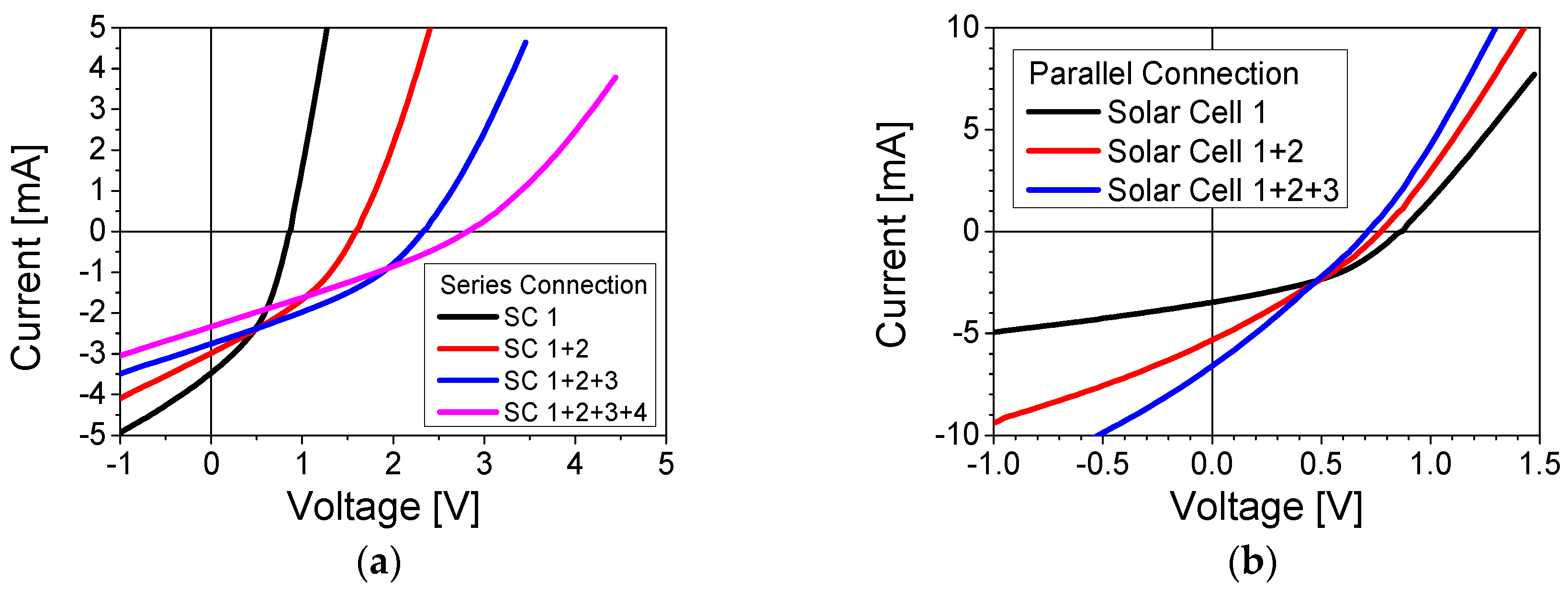
The concept for electrical interconnection described in
Section 2.3 and
Figure 3 is based on interwoven metal wires that allow a series and/or parallel connection of individual solar cells. This allows the desired current–voltage ratio to be achieved with the solar fabric. For a first rudimentary demonstration, four single solar cells were cut out of the solar fabric and manually contacted with thin metal wires (see
Figure S3 in the Supplementary Materials).
The four solar cells were first connected in a series. The results are shown in
Figure 7a. Despite the non-ideal J–V curves due to imperfect contacts, the addition of the voltages is demonstrated. Each additional solar cell increases the voltage accordingly and 2.82 V are finally achieved for all four solar cells. If the individual solar cells are connected in parallel, the currents add up, as demonstrated in
Figure 7b. As the parameters of different solar cells are not highly homogeneous, the current increase is not linear. Further research is being carried out to improve the reproducibility of solar fabrics even on inhomogeneous textiles.
For the supply of small electronic devices, such as smartphones, about 3.6 V are required, which can be achieved with five solar cells connected in a series, based on the presented results. For the required charging voltage of the integrated lithium-ion battery of 5 V, seven solar cells are needed. An estimation shows that only 20 of 1 cm2 solar cells with an efficiency of 5% connected in a series and parallel would power the average consumption of a smartphone with 100 mW on a sunny day. So, solar fabrics enable energy autonomous systems small enough for the fashion industry and scaling up to building integration (Bi-PV) and agricultural photovoltaics (Agri-PV) seems possible.
4. Conclusions
The paper demonstrates the results for a 3D flexible solar fabric based on a-Si:H thin film solar cells with a great application potential, e.g., for powering consumer electronics such as smartphones. PTFE-coated glass fiber fabric proved to be a suitable textile substrate. The layer sequence, thicknesses, and deposition processes of the solar cell layer system were optimized and adapted to the fabric requirements, resulting in short-circuit-free solar cells. An efficiency of 3.9% was achieved with an open-circuit voltage up to 876 mV and a short-circuit current up to 11.4 mA/cm2. One challenge is the still too low fill factor of 39% due to contact resistance and insufficient conductivity of the upper ITO electrode. The potential of the solar cells was shown by suns-Voc measurements without the influence of series resistance. In this case, a pseudo fill factor of almost 80% and a pseudo efficiency of 7.6% were reached. With four textile solar cells connected in a series, an open-circuit voltage of about 3 V was achieved.
In the next step, the solar cell arrays have to be directly deposited and interconnected on a fabric with interwoven metal wires. For this purpose, the PTFE layer should be applied locally to the fabric so that the contact wires remain free. In addition, deposition through a shadow mask could be replaced by full area deposition and subsequent laser structuring. Initial experiments were successfully carried out in this regard. Furthermore, there are ideas to further increase the efficiency. With a texturing of the PTFE layer and the resulting light trapping at the silver back electrode, it should be possible to increase the absorption in the solar cell for the relevant wavelengths below 700 nm, which is currently only 50% in some cases. Moreover, due to the limited conductivity of the ITO front electrode, the fill factor of the solar cells can be increased by a silver grid applied by inkjet printing on ITO or a combination of silver nanowires and TCO, as shown by the initial experiments and results [
35].
With these improvements, efficiencies in the range of 5% to 8% should be reachable. So, solar fabrics enable energy autonomous systems, e.g., in textiles and garments, and a scaling up for Bi-PV and Agri-PV seems possible. A requirement for this is the stability of the solar fabric under mechanical stress such as frequent bending, for which extensive tests are still necessary.


 ,
, 