Article

Harmonic Current Suppression of Dual Three-Phase Permanent Magnet Synchronous Motor with Improved Proportional-Integral Resonant Controller

Department of Applied Electronics, Zhejiang University, Hangzhou 310027, China
*
Author to whom correspondence should be addressed.
Energies 2025, 18(6), 1340; https://doi.org/10.3390/en18061340
Submission received: 4 February 2025 / Revised: 6 March 2025 / Accepted: 7 March 2025 / Published: 9 March 2025
(This article belongs to the Special Issue Advanced Technologies for Electrified Transportation and Robotics)

Abstract

:
The impedance of the harmonic plane in a dual three-phase permanent magnet synchronous motor (DTP-PMSM) is very low, meaning that even small harmonic voltages can induce significant harmonic currents, particularly at the fifth and seventh harmonic frequencies. These harmonic currents can severely degrade system performance and increase losses. To address this issue, the mechanism of harmonic current generation due to non-sinusoidal back electromotive force (EMF) and inverter nonlinearity is first analyzed. Then, to overcome the challenge of excessive controllers in traditional harmonic suppression strategies, a rotational coordinate transformation of the harmonic plane current is employed, which unifies the controllers and reduces their number. Since traditional proportional-integral resonant (PIR) controllers are ineffective at a high-speed region, an improved PIR controller for the harmonic plane is proposed. This controller incorporates digital delay compensation, phase compensation, and discretization correction to minimize the deviation between the discretized resonant frequency and the actual frequency. These enhancements enable harmonic suppression across the entire speed range and under varying load conditions, significantly reducing harmonic currents. Finally, the proposed harmonic current suppression strategy is experimentally validated.

1. Introduction

Traditional three-phase motor drive systems are increasingly limited by the power capabilities of electronic devices and the number of motor phases, particularly in high-power and high-reliability applications. In contrast, multi-phase drive systems offer advantages such as high output power, reduced torque ripple, and enhanced fault tolerance, making them attractive for various industrial and transportation applications. DTP-PMSMs with a π/6 phase shift are gaining popularity due to their structural similarity to traditional three-phase motors, which allows for the adoption of existing technologies developed for conventional three-phase drive systems. These drives are widely used in electric vehicles (EVs), railway traction, marine propulsion, wind power generation, and aerospace actuation systems [1,2,3,4,5]. In EVs and hybrid electric vehicles (HEVs), DTP-PMSM drives enhance operational reliability and ensure continued functionality under fault conditions. In railway traction and marine propulsion, they provide high efficiency and redundancy. In wind energy systems, their improved fault tolerance enhances system stability under grid disturbances. Additionally, in more-electric aircrafts (MEAs), these drives are employed for high-performance actuation and propulsion in aerospace applications.
However, DTP-PMSMs still face significant issues with harmonic currents, primarily caused by non-sinusoidal back-EMF [6] and inverter nonlinearity [7], etc. These factors result in harmonic currents, mainly the fifth and seventh harmonics. Since the impedance of the harmonic plane is very small, large harmonic currents are generated even with a small harmonic voltage [8]. An excessive harmonic current can lead to increased copper losses, reduced efficiency and performance, overheating, and even threaten the safe operation of the system [9]. Therefore, effective harmonic current suppression is crucial.
The suppression of harmonic currents in DTP-PMSMs has been extensively studied from three main perspectives: motor design and winding optimization [10,11,12], modulation strategy optimization [8,13,14,15,16,17,18,19,20], and control strategy optimization [21,22,23,24,25,26,27,28,29,30,31,32,33,34,35,36]. Motor design and winding optimization primarily focus on spatial harmonic suppression and pole optimization. In [10], the harmonics of two DTP-PMSM structures based on winding layout and voltage modulation are analyzed and compared. For winding optimization, a 12 slot/10 pole configuration is adopted, and star-delta windings are employed in each winding set to cancel spatial harmonics. Two three-phase inverters with a 15° phase shift are used to further reduce the seventh-order harmonic [11]. Additionally, the mutual magnetic coupling effect of dual three-phase windings is investigated, and a full-pitch winding configuration to minimize high-frequency current harmonics is proposed [12]. Modulation strategy optimization aims to reduce high-order harmonics introduced by inverter switching [13,14,15] or suppress low-order harmonics [16,17,18,19,20].
Although the space harmonics can be reduced by motor design and winding optimization, the harmonics caused by inverter nonlinearity still exist. Therefore, further optimization is needed. Modulation strategy optimization aims to reduce high-order harmonics introduced by inverter switching [14,15,16,17,18] or suppress low-order harmonics [19,20,21,22,23,24]. Various approaches have been explored, such as the multiple randomized space vector pulse width modulation (MR-SVPWM) strategy [13], advanced carrier phase-shift modulation [8], and variable switching sequence PWM [14]. For asymmetric dual three-phase motors, the high-frequency harmonics generated by different PWM techniques are compared [15]. For low-order harmonic suppression, methods are proposed such as hybrid PWM [16], continuous and discontinuous SVPWM modulations [17], minimum pulse width modulation [18], and interleaved carrier-based PWM techniques [19]. In [20], the overmodulation strategy of dual three-phase systems is extended to five-phase motors to minimize total harmonic distortion (THD). Additionally, harmonics under different modulation techniques are analyzed to address harmonics induced by inverter nonlinearity. However, while modulation-based strategies are effective in reducing switching-induced harmonics, they have limited impact on inherent motor harmonics, such as non-sinusoidal back-EMF harmonics.
Control strategy optimization actively mitigates harmonic currents by incorporating harmonic compensation or suppression algorithms into the control framework. These methods include model predictive control (MPC) [21,22,23,24,25], harmonic current feedforward compensation [26], PI (proportional-integral) control [27,28,29,30], and PIR (proportional-integral resonant) control [31,32,33,34,35,36]. In [21,22], a model-free predictive current control (MFPCC) approach based on an ultra-local model is introduced, and virtual voltage vectors are utilized to reduce harmonics. To prevent large xy current spikes, the average deception effect is considered, and a resonant extended state observer (RESO) is adopted to specifically suppress the fifth and seventh harmonics [23]. In [24,25], a deadbeat control strategy is designed with a disturbance observer to mitigate the effects of parameter mismatches. MPC offers fast response times and can simultaneously suppress multiple harmonics but requires extensive computations and high-performance control hardware. Harmonic voltage compensation is another method to suppress harmonics. A multi-input multi-output (MIMO) proportional resonant (PR) controller with automatic parameter adjustment is proposed, using harmonic voltage compensation to suppress harmonics [26]. However, this method relies on accurate harmonic detection and has a high computational complexity. For PI control and PIR control, the harmonic current suppression methods are primarily based on the vector space decoupling (VSD) mathematical model. Using a VSD transformation matrix, the DTP-PMSM variables in the natural coordinate system are mapped to three mutually orthogonal planes, which are the αβ plane, xy plane, and o1o2 plane. The fundamental currents are mapped to the αβ plane, contributing to electromechanical energy conversion, while the fifth and seventh harmonic currents are mapped to the xy plane and only produce losses. The o1o2 plane contains no current due to neutral point isolation. Thus, harmonic currents can be suppressed independently. In traditional methods, only two PI controllers are used for dq plane current control, while the current of the xy harmonic plane is controlled in an open-loop with its voltage set to zero, which fails to suppress harmonic currents [27]. To improve this, the xy-plane current is decoupled, and two PI controllers are employed in the xy plane to suppress the decoupled harmonic currents [28]. However, this approach is limited by the insufficient bandwidth of the PI controllers. To overcome this, multiple synchronous rotating coordinate systems have been proposed to convert the seventh and seventh harmonic currents to DC components, allowing simple PI controllers to be used for harmonic current suppression [29,30]. However, this method requires an additional low-pass filter (LPF) to extract the DC components, which can be difficult to implement accurately at low speeds. Moreover, the LPF introduces system delays, negatively affecting overall performance and stability. The quasi-proportional resonant (QPR) controller is another widely used method for harmonic current suppression. By introducing a bandwidth, the effects of variations in the resonant frequency can be mitigated. In practical applications, a PI controller is typically paired with a QPR controller, forming a PIR controller to enable both DC component tracking and harmonic current suppression [31,32,33,34,35,36]. In [31], QPR controllers are designed to suppress the fifth and seventh harmonics in the xy harmonic plane. However, this method requires four QPR controllers, resulting in a complex control structure. To simplify the system, an anti-synchronous reference frame has been developed to transform the fifth and seventh harmonic currents into a sixth harmonic current [32,33]. However, higher-order harmonic currents are not addressed. Moreover, at high speeds, the frequencies of the sixth harmonic current increases and may encounter a low carrier ratio condition [34]. Digital delay reduces the phase margin of the PIR controller’s resonant term, thereby compromising overall system stability. In such cases, the digital delay cannot be ignored, and phase margin compensation for the resonant term is necessary. Otherwise, harmonic currents will worsen. Furthermore, different discretization methods affect the characteristics of PIR controllers in varying ways [35]. The methods typically employ bilinear transformation to discretize PIR controllers, which leads to deviations between the discretized resonant frequency and the actual resonant frequency. This reduces suppression performance, especially at high speeds. Although stability is improved through direct design and optimization of the resonant controller in the discrete domain [36], it remains impossible to simultaneously track the target value and mitigate system interference. The harmonic suppression method based on the PIR controller is well suited for actively mitigating motor harmonic currents, ensuring zero steady-state error in harmonic suppression. However, it exhibits limited adaptability to variable-speed conditions and has a constrained suppression bandwidth, making it less effective across a wide frequency range.
To address these issues, this article proposes a harmonic current suppression strategy based on improved PIR controllers with digital delay compensation, phase compensation, and discretization correction. The main contributions of this work are as follows:
(1)
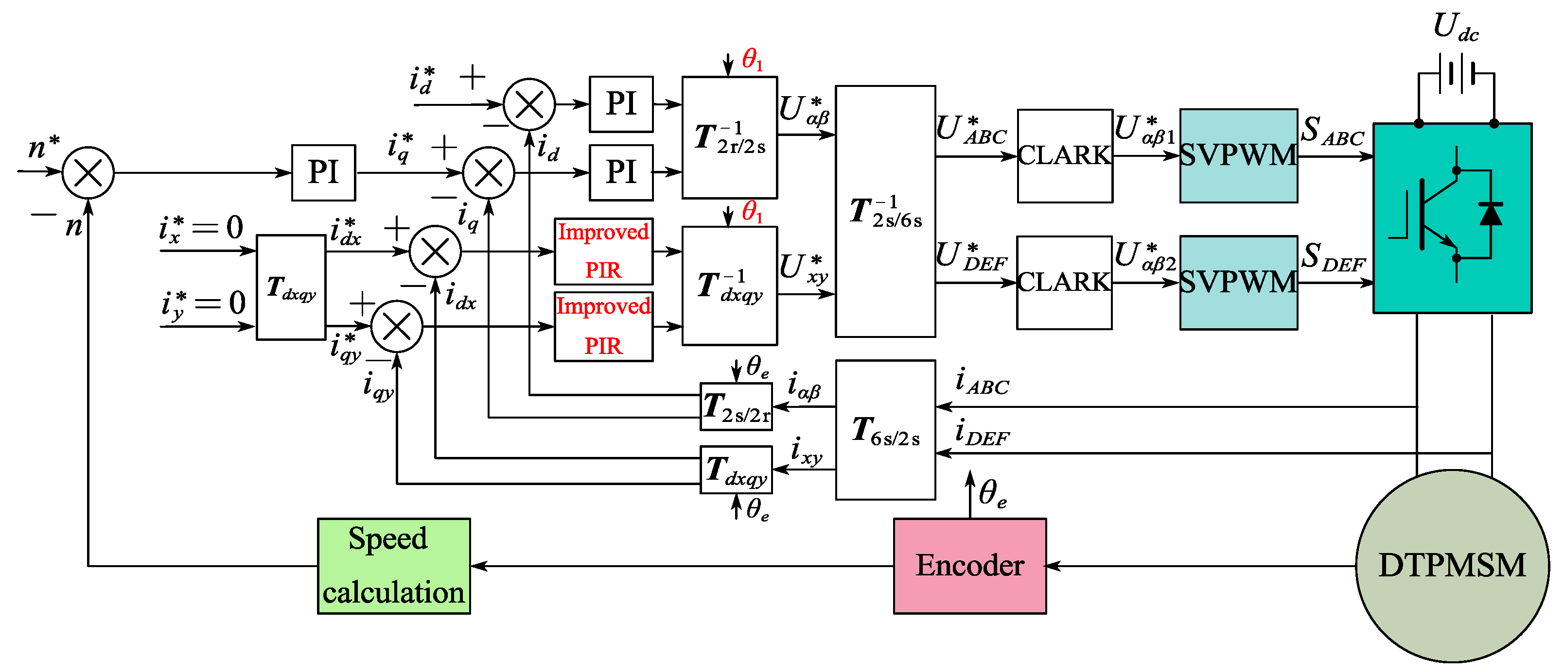
By transforming the fifth and seventh harmonic currents in the xy plane into sixth harmonic currents via coordinate transformation, only two improved PIR controllers are required to achieve harmonic suppression. This reduces the number of controllers and simplifies the control structure.
(2)
Digital delay compensation is achieved by correcting the angles in the coordinate transformation, while phase compensation is implemented by adjusting the transfer function of the resonant term. These improvements enhance both system stability and harmonic current suppression, especially at high speeds.
(3)
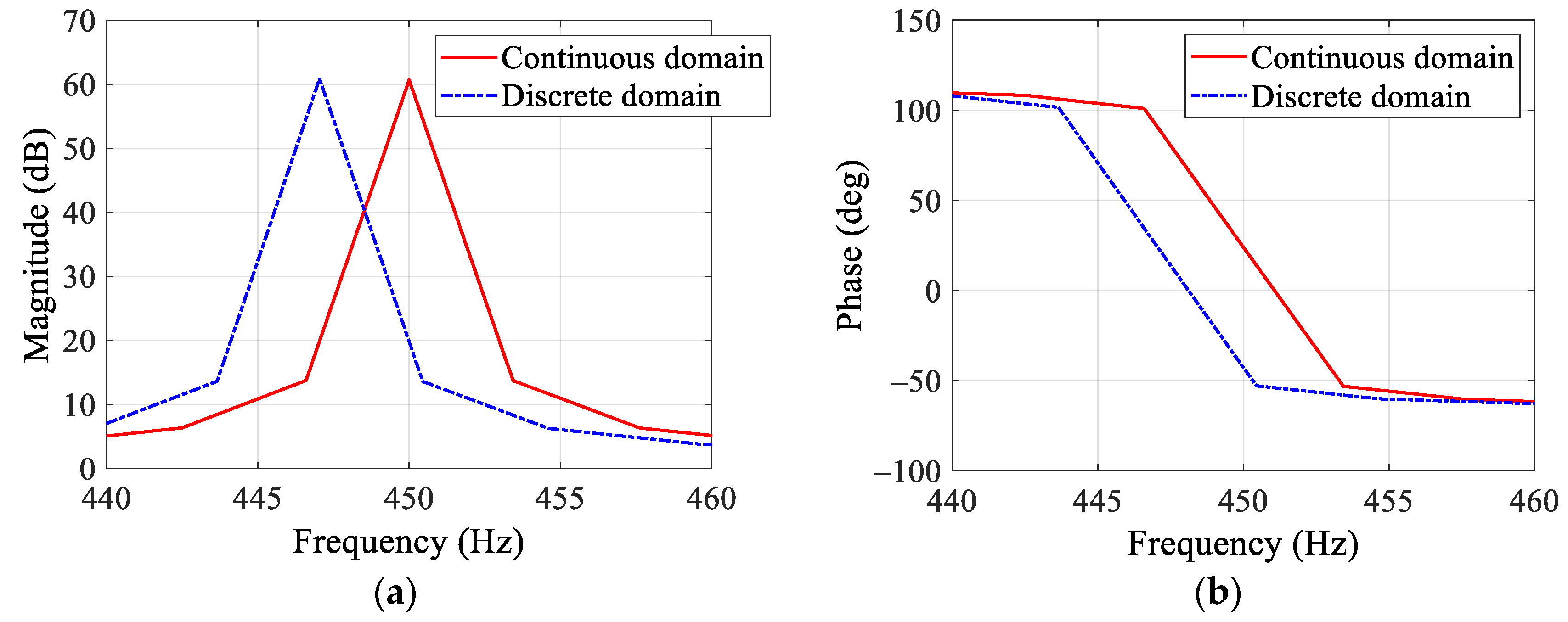
The coefficients of the bilinear transformation formula are corrected to maintain consistent amplitude–frequency and phase–frequency characteristics between the continuous and discrete transfer functions. This eliminates deviations between the discretized and actual resonant frequencies, ensuring effective harmonic current suppression at high speeds.
The rest of this article is organized as follows. The mathematical model and harmonic current analysis are given in Section 2. Section 3 outlines the harmonic current suppression based on improved PIR controllers with digital delay compensation, phase compensation, and discretization correction. Section 4 presents the experimental verification by comparing the experimental results with PI controllers, PIR controllers, and improved PIR controllers. Finally, the conclusion is drawn in Section 5.

2. Modeling and Harmonic Current Analysis of DTP-PMSM

2.1. Mathematical Model

An accurate and simplified mathematical model of the DTP-PMSM is crucial for facilitating theoretical analysis and the development of control strategies. The schematic diagram of the DTP-PMSM drive system is presented in Figure 1. The DTP-PMSM features two sets of three-phase windings, labeled ABC and DEF, with their respective neutral points denoted as N1 and N2. To mitigate the sixth-order torque ripple, the two winding sets are phase-shifted by π/6. Each winding set is powered by a two-level three-phase inverter.
The mathematical model of the DTP-PMSM in the natural coordinate system is characterized by its high-order, nonlinear, and strong coupled properties, which complicate system analysis. To simplify this complexity, a VSD mathematical model is utilized [27]. The VSD transformation matrix is expressed as
T 6 s / 2 s = α β x y o 1 o 2 = 1 3 1 1 2 1 2 3 2 3 2 0 0 3 2 3 2 1 2 1 2 1 1 1 2 1 2 3 2 3 2 0 0 3 2 3 2 1 2 1 2 1 1 1 1 0 0 0 0 0 0 1 1 1
To enable rotor flux-oriented vector control (FOC), similar to traditional three-phase motors, the variables are transformed from the αβ stationary reference frame to the dq synchronous rotating reference frame using a coordinate transformation. The extended rotation matrix for the DTP-PMSM is given as
T 2 s / 2 r = cos θ e sin θ e sin θ e cos θ e
Using (1) and (2), the mathematical model of the DTP-PMSM can be derived. The voltage and torque equations are expressed as
u d u q u x u y = R s i d i q i x i y + L d 0 0 0 0 L q 0 0 0 0 L l s 0 0 0 0 L l s d d t i d i q i x i y + ω e L q i q L d i d + ψ f 0 0
T e = 3 n p ψ f i q + L d L q i d i q

2.2. Harmonic Current Analysis

In the DTP-PMSM drive system, harmonic currents primarily result from inverter nonlinearity, winding parameter inconsistencies, and non-sinusoidal back-EMF. Since high-order harmonic currents contribute minimally, this article focuses primarily on the dominant fifth and seventh harmonic currents.

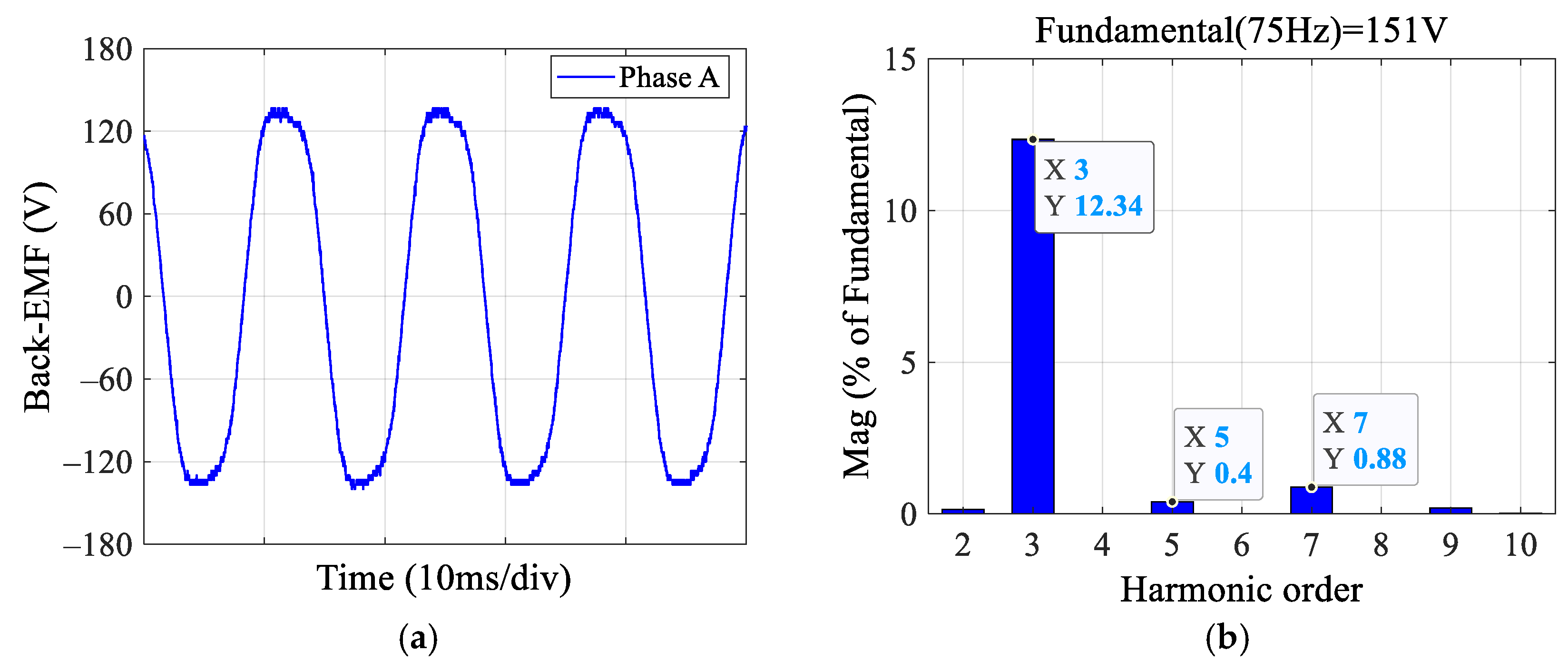
2.2.1. Non-Sinusoidal Back-EMF

In practical applications, the back-EMF of DTP-PMSM is not perfectly sinusoidal, inevitably introducing harmonics. Figure 2 shows the phase-A back-EMF waveform of the prototype DTP-PMSM and its fast Fourier transform (FFT) results. The term “Mag (% of Fundamental)” represents the amplitude of each harmonic component as a percentage of the fundamental component’s amplitude. Since the fundamental component inherently accounts for 100%, it is omitted in the FFT results to emphasize the relative proportions of the harmonic components. As illustrated in Figure 2b, the back-EMF of phase A contains significant third, fifth, and seventh harmonic components, which account for 12.34%, 0.40%, and 0.88% of the fundamental component, respectively. Since the prototype employs a Y-connected winding with isolated neutral points for both sets of three-phase windings, the third harmonic voltage does not generate third harmonic currents. Although the amplitudes of the fifth and seventh harmonic voltages are relatively small, they still induce substantial fifth and seventh harmonic currents due to the very low impedance in the xy harmonic plane.

2.2.2. Inverter Nonlinearity

During the switching process, dead time is introduced between the upper and lower switches to prevent short circuits, which leads to distortion in the inverter’s output voltage. According to [37], the average voltage error induced by inverter nonlinearity can be approximated as a square wave signal. By performing Fourier decomposition and considering only the fifth and seventh harmonic currents, the voltage error in the xy harmonic plane can be expressed as [38]
Δ U x 4 Δ U d π 1 5 sin 5 ω e t + γ + 1 7 sin 7 ω e t + γ 7 Δ U y 4 Δ U d π 1 5 cos 5 ω e t + γ + 1 7 cos 7 ω e t + γ
ΔUd is caused by dead time, switch voltage drop, and diode forward voltage drop, which can be calculated as
Δ U d = T d + T o n T o f f T s U d c U s a t + U d U s a t + U d 2
In the xy harmonic plane, the impedance of the fifth and seventh harmonic planes is given by
Z 5 = R s 2 + 5 ω e L l s 2 Z 7 = R s 2 + 7 ω e L l s 2
Since the stator leakage inductance is much smaller than the dq-axis inductance, from (7), it can be seen that even small harmonic voltages in the xy harmonic plane can generate large harmonic currents. Using (5) and (7), the fifth and seventh harmonic currents in the xy harmonic plane are expressed as
i x 5 = i y 5 = 4 Δ U d sin 5 ω e t + γ φ 5 5 Z 5 i x 7 = i y 7 = 4 Δ U d sin 7 ω e t + γ φ 7 7 Z 7

3. Improved PIR Controller

3.1. Unification of PIR Controllers

The PIR controller consists of a PI controller and a QPR controller in parallel. The PI controller is used to control the DC component, while the QPR controller is used to control the fifth and seventh harmonic currents. The transfer function of the PIR controller in the continuous domain is given by
G P I R s = K p + K i s + K p r + K r ω c s s 2 + 2 ω c s + ω n 2
where ωn varies with speed.
For harmonic suppression in the xy harmonic plane, the traditional method is to cascade two PIR controllers: one for controlling the fifth harmonic current and the other for the seventh harmonic current. However, this method requires four PIR controllers and involves numerous parameters, making the system relatively complex. To simplify the control, this article employs a coordinate transformation to convert the fifth and seventh harmonic currents in the xy plane to the sixth harmonic current. In other words, the harmonic currents in the xy harmonic plane are mapped to the dxqy harmonic plane, where two controllers are sufficient to suppress the fifth and seventh harmonic currents. The transformation matrix from the xy harmonic plane to the dxqy harmonic plane is given by
T d x q y = cos θ e sin θ e sin θ e cos θ e
The unified dual PIR controllers for the xy plane are shown in Figure 3. The parameter design for the PIR controller is provided in [39], so it is not discussed here. Then, the open-loop Bode diagram of the harmonic current loop based on traditional PIR controllers is illustrated in Figure 4. Clearly, the current loop has a low phase margin at the resonant frequency, which adversely affects the harmonic suppression performance and stability of the system. This issue arises from the presence of digital delay. This delay reduces the system’s phase margin, thereby compromising its stability.

3.2. Digital Delay Compensation and Phase Compensation

For digital controllers using the SVPWM modulation strategy, the digital delay is approximately 1.5 times the control cycle. To mitigate this, digital delay compensation is required. The correction is applied after the PIR controller, ensuring that the control voltage output is accurately applied after the digital delay in the SVPWM process. Consequently, the transformation angles must be compensated. The coordinate transformation matrices with digital delay compensation are expressed as
T 2 r / 2 s θ 1 = cos θ 1 sin θ 1 sin θ 1 cos θ 1 = cos θ e + 1.5 T s ω e sin θ e + 1.5 T s ω e sin θ e + 1.5 T s ω e cos θ e + 1.5 T s ω e
T d x q y 1 θ 1 = cos θ 1 sin θ 1 sin θ 1 cos θ 1 = cos θ e + 1.5 T s ω e sin θ e + 1.5 T s ω e sin θ e + 1.5 T s ω e cos θ e + 1.5 T s ω e
Digital delay compensation only addresses the delay in the system, thereby improving the overall phase margin. However, this delay also diminishes the phase margin of the controller, necessitating phase compensation to further enhance system stability. Since the phase margin of the PI control term is sufficiently large, phase compensation is not needed for it. In contrast, the resonant term has a smaller phase margin, which is further reduced by the digital delay, potentially destabilizing the system. Therefore, phase compensation is applied only to the resonant term.
As shown in Figure 4, phase compensation for the resonant term requires adding a phase compensation angle at the resonant frequency to counteract the phase lag caused by digital delay. Thus, the transfer function of the resonant term with phase compensation can be written as
G P C R s = 1 2 K r ω c e + j φ p c s j ω n + ω c + K r ω c e j φ p c s + j ω n + ω c                           = K r ω c s cos φ p c ω n sin φ p c + cos φ p c ω c 2 s 2 + 2 ω c s + ω n 2
where φpc is the phase compensation angle, given by 1.5ωeTs.
Since the resonant frequency is much greater than the cutoff frequency, (13) can be further simplified as
G P C R s = K r ω c s cos φ p c ω n sin φ p c s 2 + 2 ω c s + ω n 2
Thus, the open-loop Bode diagram of the harmonic current loop based on the improved PIR controllers is shown in Figure 5. After the introduction of digital delay compensation and phase compensation, the phase margin significantly increases, improving system stability. Meanwhile, the system’s gain at the resonant frequency remains unchanged. Finally, the control block diagram based on the dual improved PIR controllers with digital delay compensation and phase compensation is illustrated in Figure 6.

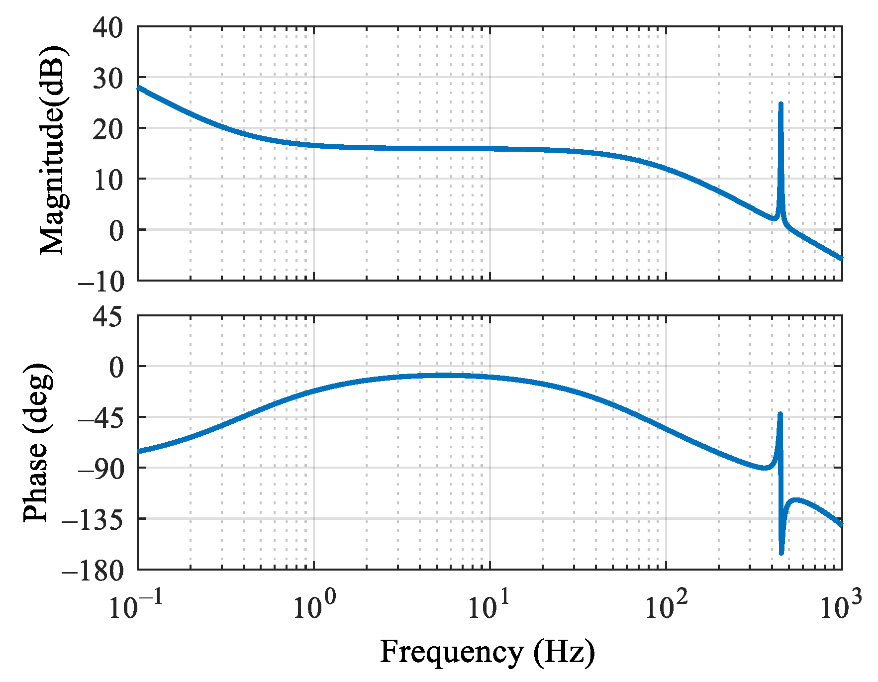
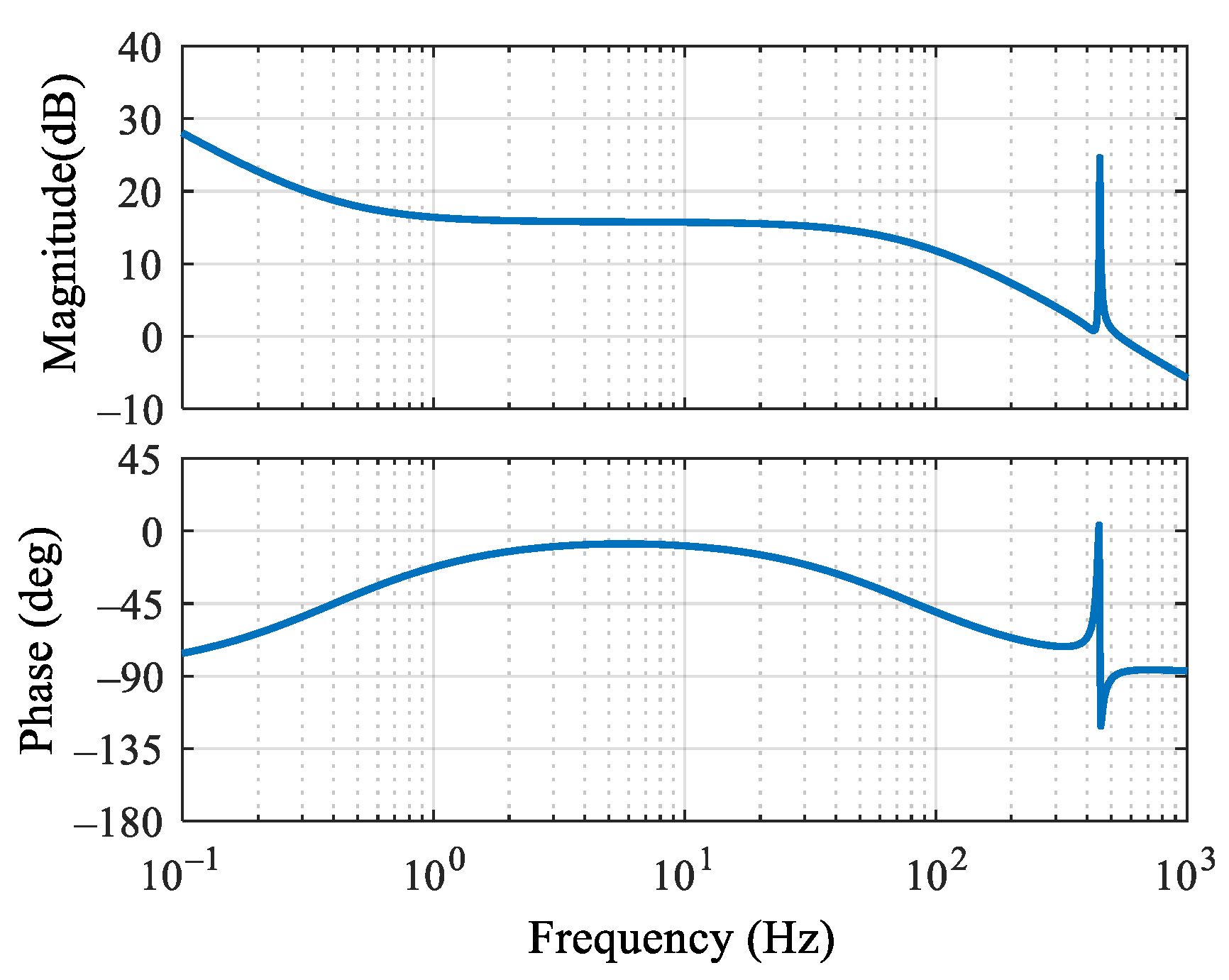
3.3. Discretization Correction

Bilinear transformation is one of the most commonly used methods for discretizing controllers. The transformation formula is given by
s = 2 T s z 1 z + 1
Figure 7 compares the continuous and discretized amplitude– and phase–frequency characteristics of the improved PIR term using bilinear transformation, at a speed of 1500 r/min and a sampling frequency of 10 kHz. As shown in Figure 7, in the continuous domain, the resonant frequency is 450 Hz. After discretization, the resonant frequency becomes 447 Hz, resulting in a deviation of 3 Hz, corresponding to an electrical angular velocity of 18.84 rad/s. The designed cutoff frequency is 5 rad/s. Thus, using the traditional bilinear discretization method for the controller leads to a deviation between the discretized improved PIR frequency and the actual harmonic current frequency. As the frequency increases, the error grows, which results in ineffective harmonic current suppression at high speeds.
To mitigate the resonant frequency deviation caused by bilinear transformation, the transformation formula in (15) is improved as follows:
s = K m z 1 z + 1
where Km is used to adjust the discretized resonant frequency to align with the actual resonant frequency.
Substituting (16) into (14) yields,
G P C R z = K r ω c K m cos φ p c z 2 1 ω n sin φ p c z + 1 2 K m 2 z 1 2 + 2 ω c K m z 2 1 + ω n 2 z + 1 2
where GPCR (z) represents the discrete-domain transfer function of the resonant term with phase compensation.
The actual resonant frequency after discretization can be derived by solving the poles of (17):
ω z = arctan 2 K m ω n 2 ω c 2 K m 2 ω n 2 1 T s
To ensure that the discretized resonant frequency matches the actual resonant frequency, let ωz = ωn. Solving this condition gives the correction factor Km:
K m = ω n tan 0.5 ω n T s
By substituting (19) into (17), the improved discrete-domain transfer function is obtained as
G D P C R z = K r ω c 2 ω n sin ω n T s cos φ p c 1 z 2 sin φ p c 1 cos ω n T s 1 + 2 z 1 + z 2 1 + z 2 2 sin ω n T s z 1 + ω c ω n sin ω n T s 1 z 2
Figure 8 shows a comparison of the amplitude– and phase–frequency characteristics of the improved PIR term under continuous and discrete domains, with discretization correction, at a speed of 1500 r/min and a sampling frequency of 10 kHz. The results demonstrate that introducing the correction factor eliminates the frequency deviation, ensuring that the discretized resonant frequency matches the actual resonant frequency. This alignment preserves the harmonic current suppression effect. Consequently, using (20) alongside the discrete-domain transfer function of the PI term enables the implementation of the improved PIR controller in code. This approach effectively suppresses the fifth and seventh harmonic currents in the DTP-PMSM.

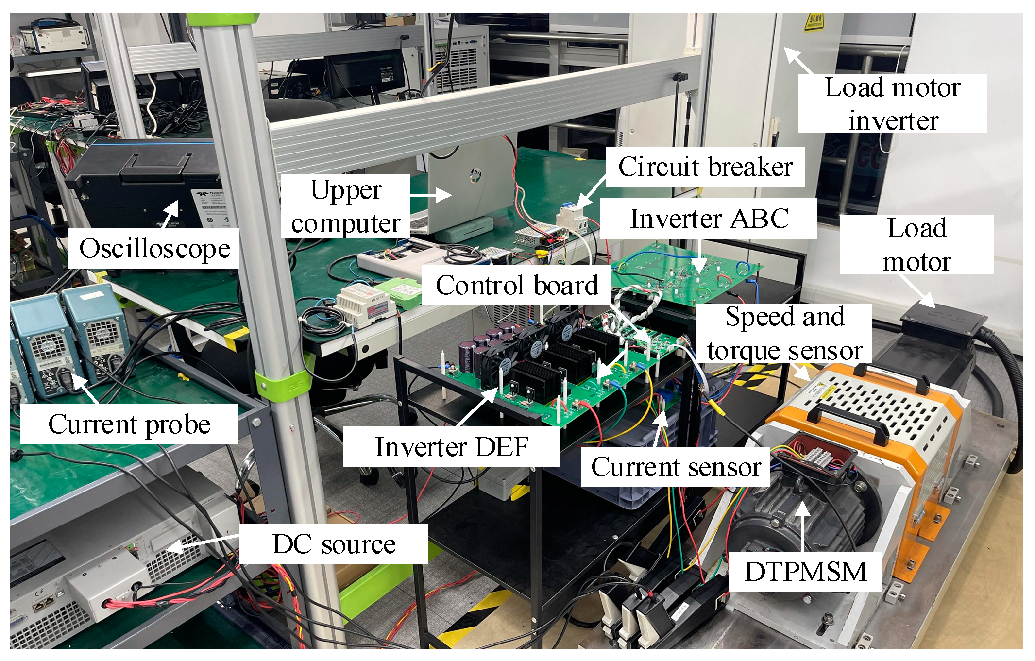
4. Experimental Verification

A prototype platform for the DTP-PMSM drive system was constructed to validate the proposed harmonic suppression strategy. The platform consists of a DTP-PMSM prototype, a control board, two IGBT-based three-phase inverters, a current sampling board, and a speed-torque sensor, as shown in Figure 9. The control board employs a DSP control chip from Texas Instruments (model: TMS320F28335). The IGBT switching frequency is set to 10 kHz, matching the current loop control frequency. The dead time is configured to 500 ns. The PWM signals generated by the control board are routed through a driver circuit to produce the drive signals for the three-phase inverters. The load is provided by a variable-frequency drive that controls a three-phase asynchronous motor. The current sampling board uses six current sensors from LEM (model: LA25-NP) to measure phase currents. Additionally, a speed-torque sensor is included to measure speed and torque. The parameters of the dual three-phase motor prototype are listed in Table 1.

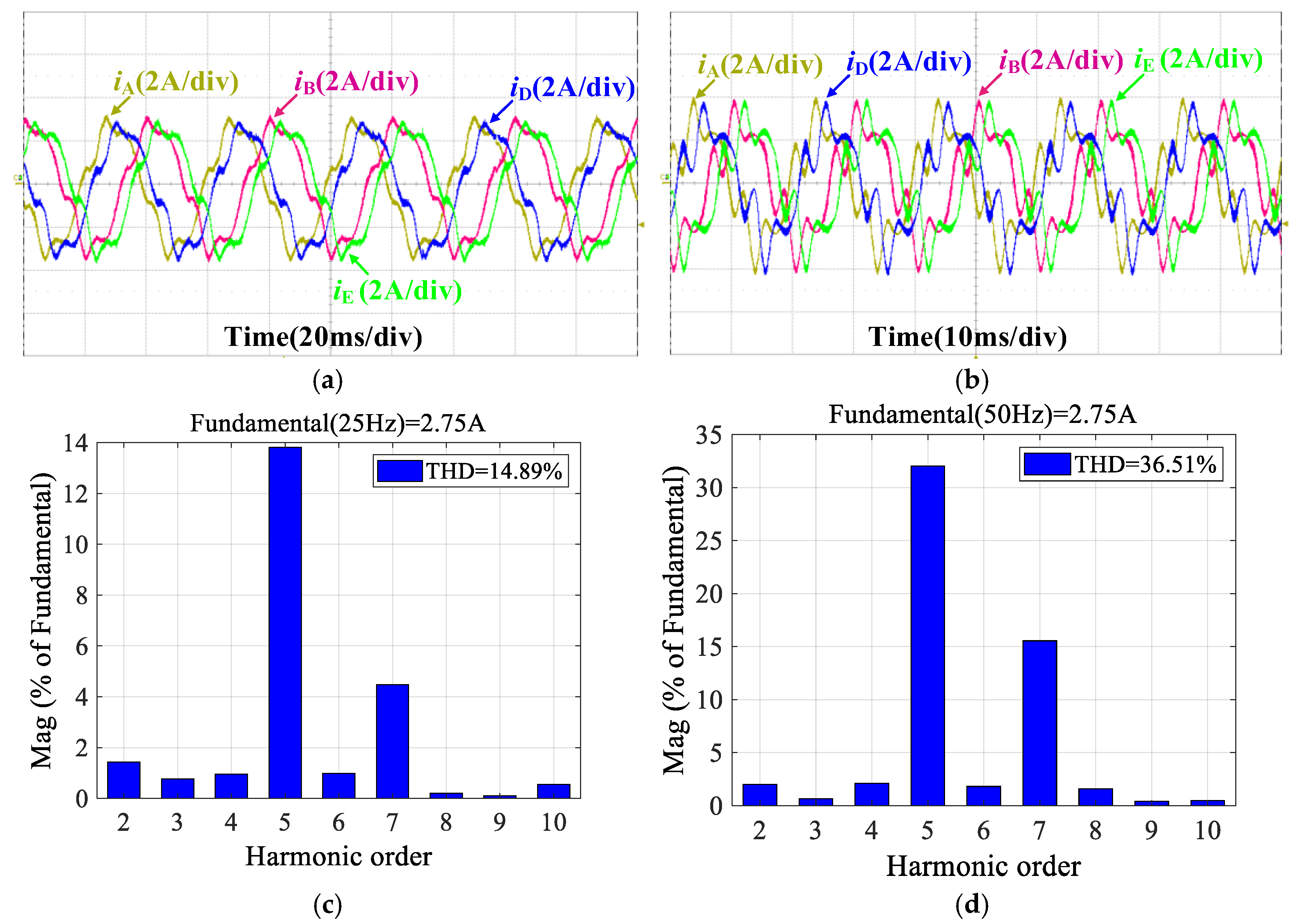
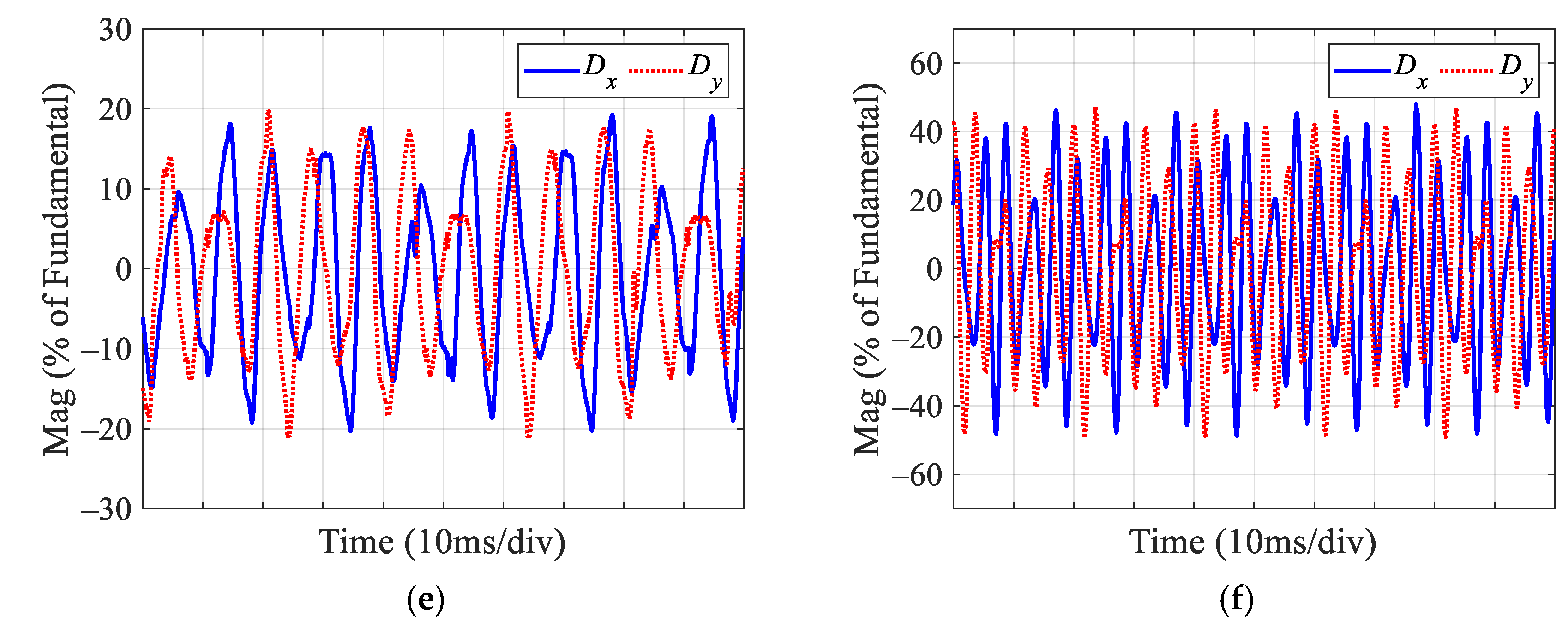
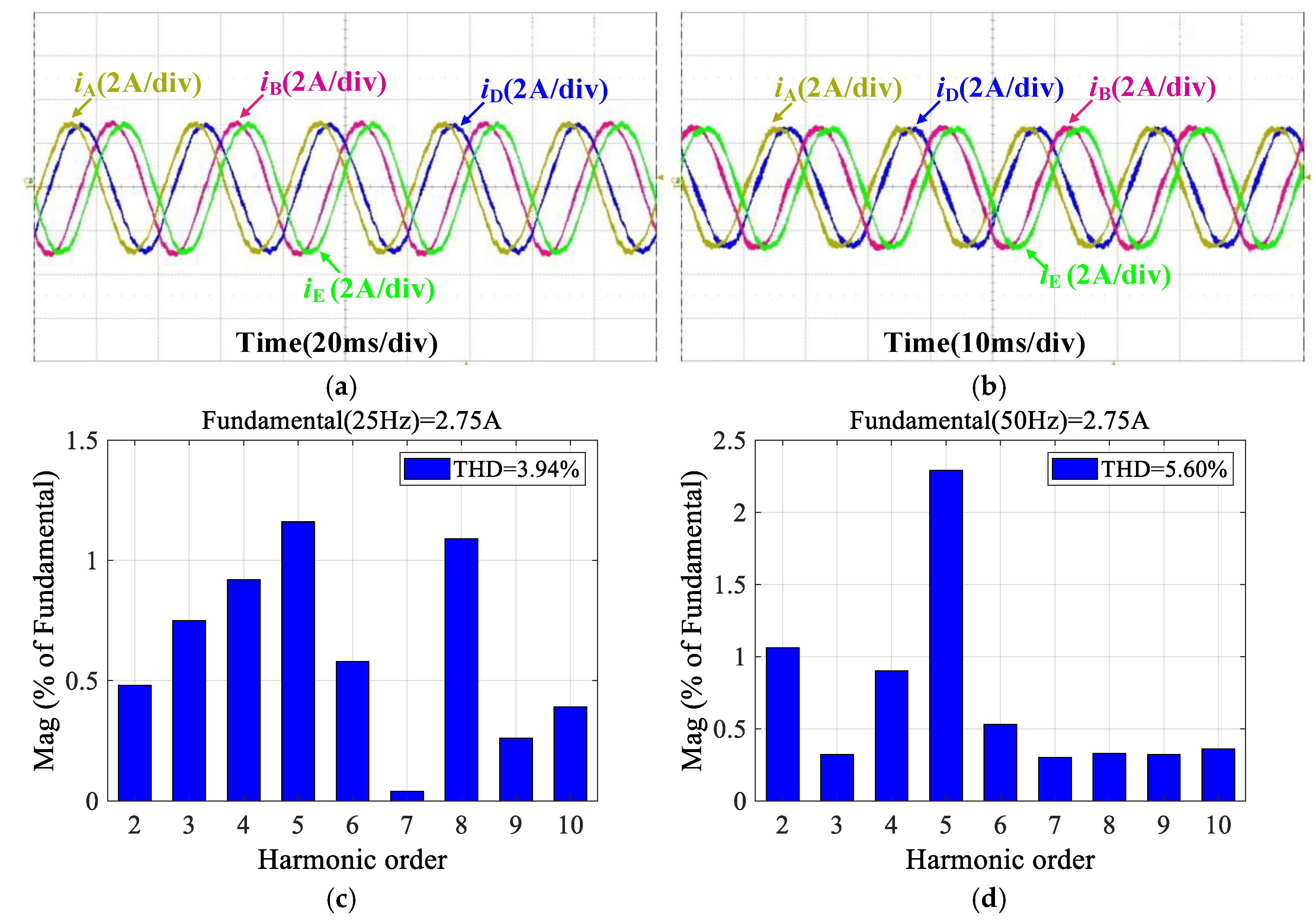
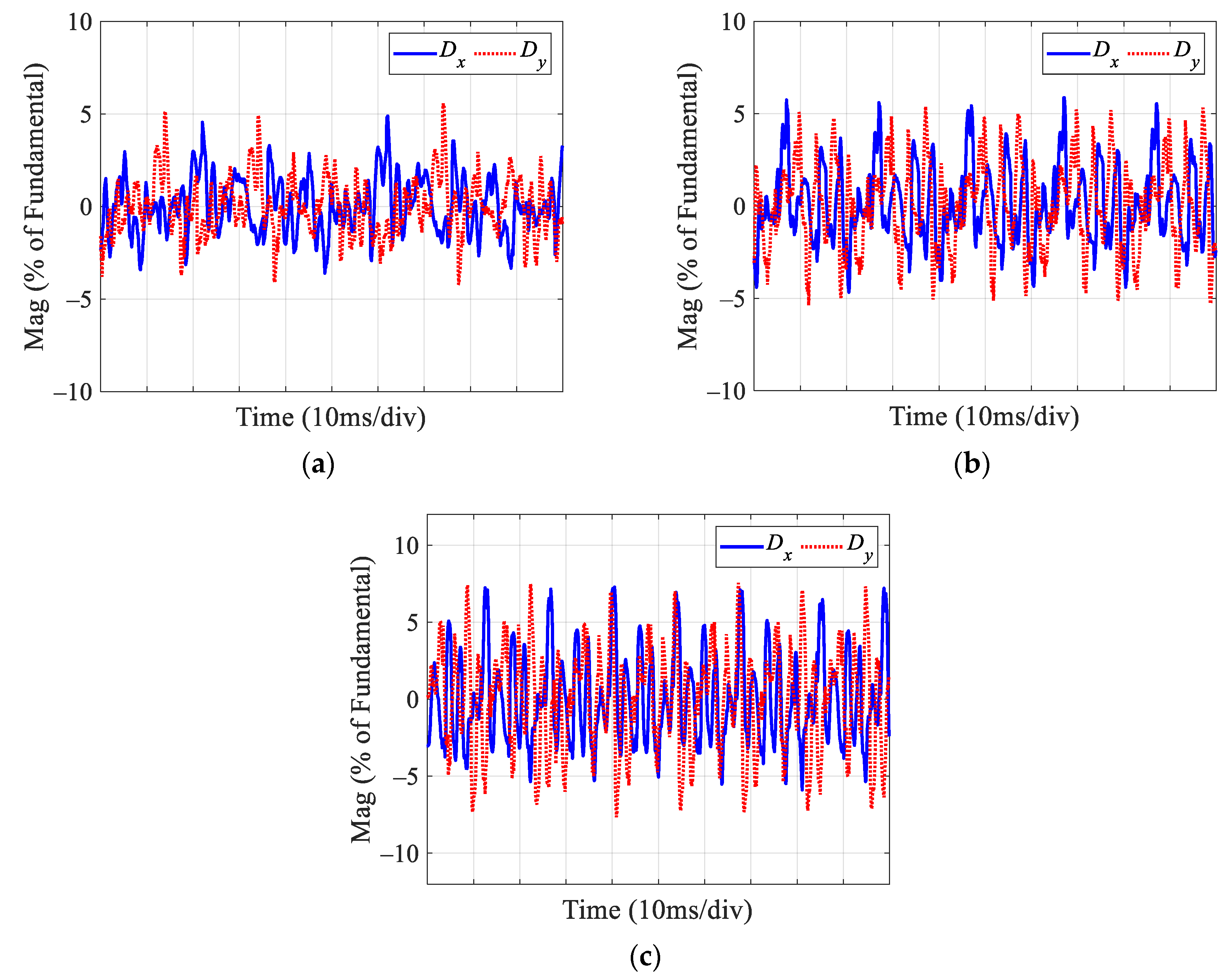
4.1. Traditional Dual PI Controllers

Figure 10 presents the experimental results with an xy-plane current using dual PI controllers at different speeds with a medium load torque of 7.5 N·m. As shown in Figure 10, the harmonic content in the phase current significantly increases with increasing speed. The THD increases from 14.89% at 500 r/min to 36.51% at 1000 r/min. This is attributed to the prototype motor, which is adapted from a traditional three-phase PMSM and contains substantial harmonic components in its back-EMF. As speed increases, the proportion of back-EMF rises, leading to a corresponding rise in harmonic currents. The xy-plane current directly reflects the magnitude of these harmonic currents within the motor. To more accurately represent the harmonic currents, Dx and Dy are used. As shown in Figure 10e,f, Dx and Dy remain substantial even when controlled by the PI controller and increase with the speed. This is because the PI controller cannot effectively track sinusoidal references, preventing it from suppressing harmonic currents even when the reference value is set to zero. These results indicate that the traditional control of xy-plane, based on dual PI controllers, fails to fully exploit the performance potential of the DTP-PMSM drive system. Additionally, the presence of significant harmonic currents leads to increased motor losses and thermal stress on the system, underscoring the need for more effective harmonic suppression strategies.

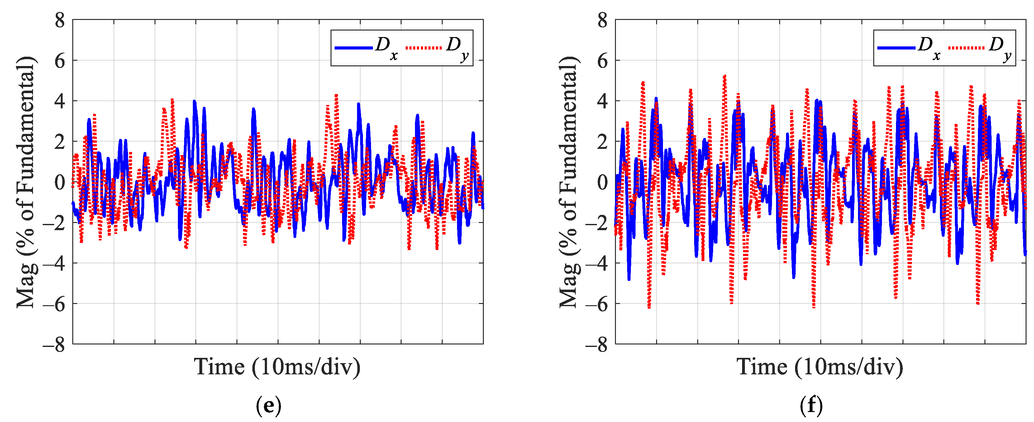
4.2. Traditional Dual PIR Controllers

To suppress the fifth and seventh harmonic currents, the traditional PIR controllers are employed. The dq-plane currents are controlled by PI controllers with unchanged parameters. Figure 11 presents the experimental results with the xy-plane current using dual PIR controllers at different speeds with a load torque of 7.5 N·m. At 500 r/min, the THD of the phase current decreases from 14.89% to 3.94%. At 1000 r/min, the THD drops from 36.51% to 5.60%. The xy-plane current is significantly reduced, meaning that the fifth and seventh harmonic currents are effectively suppressed. These results demonstrate the effectiveness of dual PIR controllers in the xy plane for harmonic suppression at low and medium speed.
Figure 12 shows the experimental results with the xy-plane current using traditional dual PIR controllers at a speed of 1100 r/min and a load torque of 7.5 N·m. As the speed increases to 1100 r/min, it can be observed that the traditional dual PIR controllers fail to suppress harmonic currents and instead introduce additional harmonic components. Consequently, the THD of the phase current significantly rises to 50.15%, and the xy-plane current also increases substantially. This behavior can be attributed to two factors. First, the digital delay reduces the phase margin of the resonant term in the PIR controller. Second, the conventional bilinear discretization method introduces a discrepancy between the discrete resonant frequency and the actual resonant frequency. This discrepancy leads to the introduction of additional harmonic components, ultimately compromising the robustness of the system.

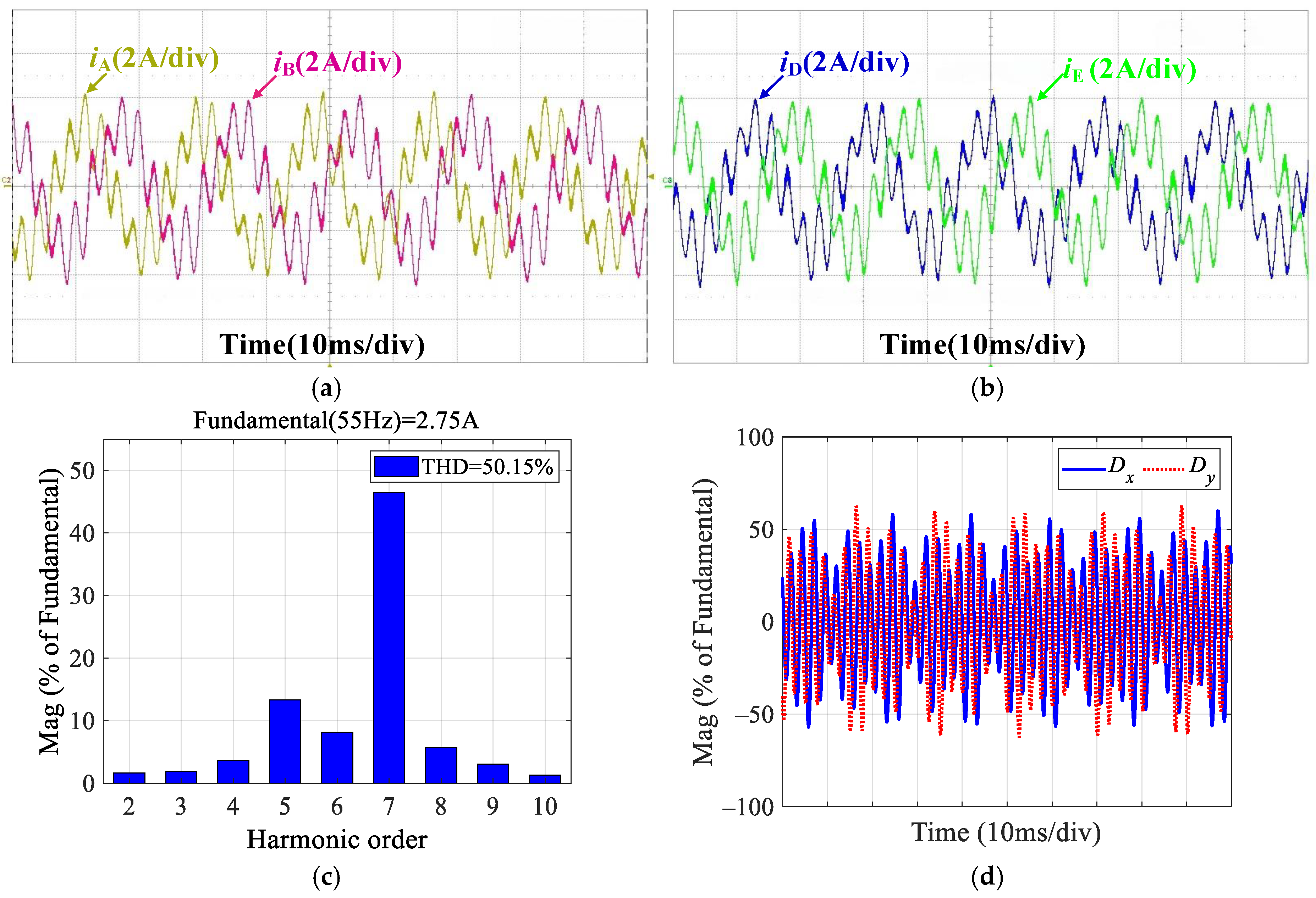
4.3. Proposed Dual Improved PIR Controllers

To address the aforementioned issues, a harmonic current suppression strategy based on dual improved PIR controllers for the entire speed range is proposed, incorporating digital delay compensation, phase compensation, and discretization correction. The experimental results with the xy-plane current using dual improved PIR controllers under different speeds at a load of 7.5 N·m are shown in Figure 13 and Figure 14. As shown in Figure 13, at low speed (500 r/min) and medium speed (1000 r/min), the THD of the phase current for the improved PIR controller is 3.82% and 5.61%, respectively. Compared to the traditional PIR controller, the harmonic current suppression effect is similar. Compared with Figure 12, the improved PIR controller achieves a phase current THD of 5.72% at high speed (1500 r/min), still effectively suppressing the harmonic currents without introducing additional harmonic components. Figure 14 also shows that the xy-plane current at different speeds has significantly decreased, demonstrating the effectiveness of the proposed improved PIR controller for harmonic current suppression across the entire speed range.
To further verify the effectiveness of the proposed dual improved PIR controller under different loads, Figure 15 presents the experimental results with the proposed method at a speed of 1500 r/min under light load (4 N·m) and heavy load (14 N·m) conditions. By comparing Figure 15a–d with Figure 13c,f, it can be seen that, at the same speed, the THD of the phase current decreases as the load increases. Under light load conditions, the THD of the current is higher. This is because the duty cycle is lower, and the effect of the inverter dead time on the phase current is more pronounced, leading to a larger harmonic voltage and higher THD. Additionally, the relatively larger speed fluctuations at light load also result in greater harmonics and higher THD. By comparing Figure 15e,f with Figure 14c, it can be observed that Dx and Dy are very small under different load conditions. According to these experimental results under various load conditions, it is evident that the improved PIR controller also maintains good robustness to load changes.

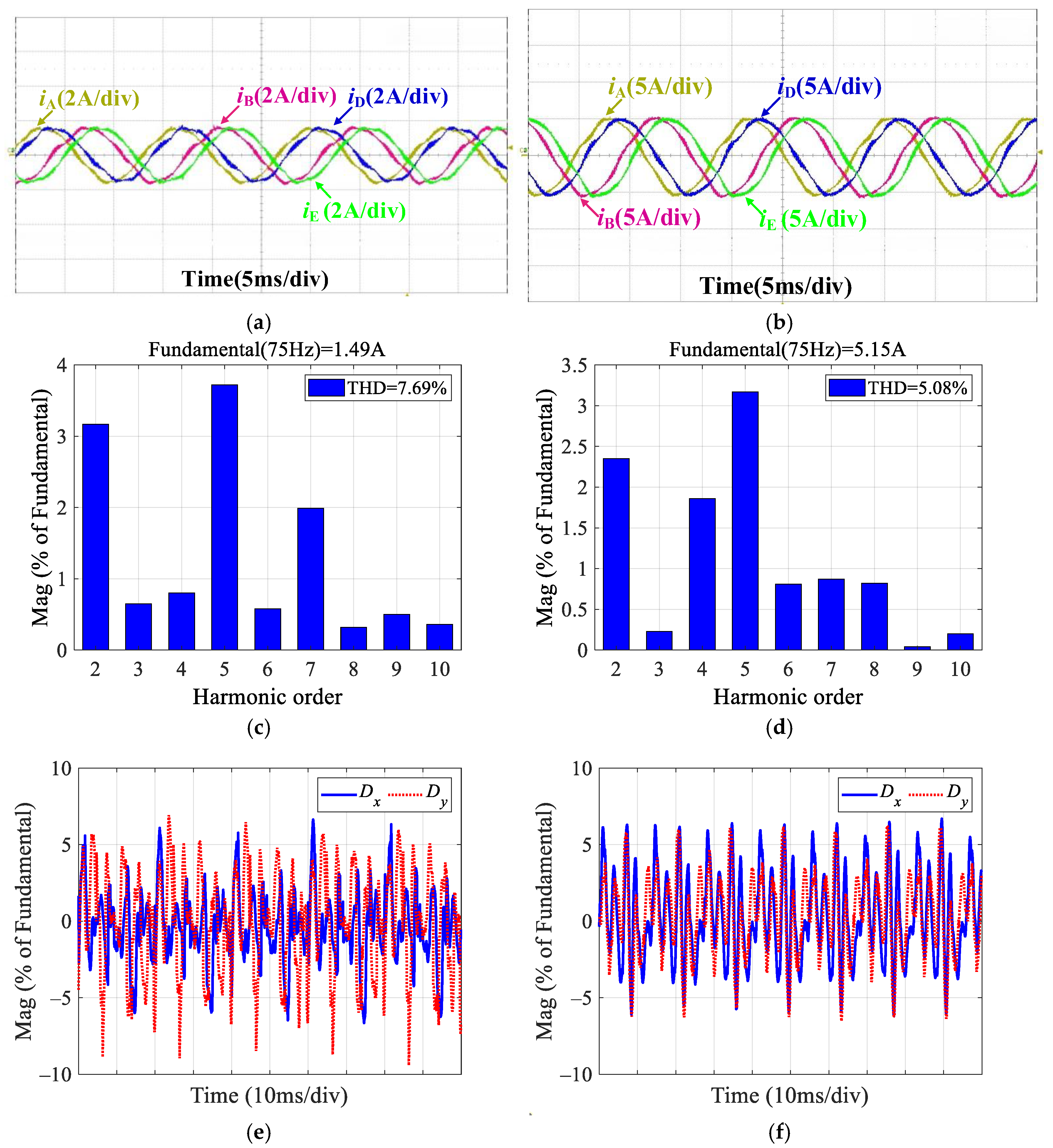
4.4. Results, Comparison, and Analysis

The THD of different controllers under various speed and load conditions is summarized in Table 2. The term “*” in Table 2 represents the THD under the particular operating condition, which is excessively high and is therefore not considered. To further validate the performance of the proposed dual improved PIR controllers, Table 3 compares the efficiency improvement and response time for different controllers. The efficiency improvement is evaluated under a speed of 1000 r/min with a load torque of 7.5 N·m, while the response time is assessed at a speed of 500 r/min, where the q-axis current reference steps from 1 A to 4 A. The response time is defined as the duration required for the current to stabilize within ±5% of the final value after the initial response.
In Table 3, the ratio of harmonic copper losses to fundamental copper losses is used as an indirect measure of efficiency improvement due to limitations in the direct efficiency measurement. Specifically, the additional copper losses caused by the first ten harmonic currents are considered. rcu is calculated as
r c u = n = 2 10 I n r m s 2 I r m s 2
As shown in Table 2 and Table 3, both the traditional dual PIR controllers and the proposed dual improved PIR controllers significantly reduce current THD compared to the traditional dual PI controllers. Consequently, harmonic losses are greatly minimized, indirectly contributing to improved system efficiency. However, due to the effects of digital delay and discretization, the harmonic suppression effectiveness of traditional dual PIR controllers is limited at high speeds. In contrast, the proposed dual improved PIR controllers not only retain the same harmonic suppression capability of traditional dual PIR controllers but also extend the effective speed range of harmonic suppression, ensuring robust performance even at higher speeds, further validating the effectiveness of the proposed method.
Regarding response time, the traditional dual PI controllers exhibit longer settling times due to their limited harmonic suppression capability, which delays system stabilization. In comparison, both the traditional dual PIR and proposed dual improved PIR controllers achieve faster response times by incorporating a resonant component that effectively suppresses harmonics. However, the proposed dual improved PIR controller exhibits a slightly longer response time than the traditional dual PIR controller due to the additional digital delay compensation, phase compensation, and discretization correction processes.
To verify the reliability and consistency of the experimental results, two additional experiments are conducted, and statistical analysis is performed on the results. The average error is calculated and presented in Table 4. The meaning of “*” in Table 4 is the same as that in Table 2. From Table 4, it can be observed that the average error among the three experiments is minimal, indicating good repeatability and reliability of the experimental results. This further validates the stability and consistency of the proposed control strategy, thereby enhancing the credibility of the research conclusions.

5. Conclusions

This article proposes a harmonic current suppression strategy based on an improved PIR controller for DTP-PMSM drive systems. The mechanism of harmonic current generation, caused by back-EMF and inverter nonlinearity, is analyzed. The results reveal that the primary harmonic currents are the fifth and seventh harmonics. According to the VSD theory, harmonic current suppression can be achieved by controlling the currents of the xy harmonic plane. Due to the limited bandwidth, the effectiveness of traditional PI controllers in suppressing harmonic currents is restricted. Therefore, PIR controllers are employed to suppress harmonic currents and reduces the number of controllers by performing coordinate transformation on the currents of xy-plane. By incorporating digital delay compensation, phase compensation, and discretization correction, the phase margin and stability of the system are improved, mitigating frequency deviations introduced by the traditional bilinear transformation discretization method. The proposed method with improved PIR controllers for xy-plane currents extends harmonic current suppression for the entire speed. The effectiveness of the proposed method is validated through experimental comparisons with traditional PI and PIR controllers for xy-plane currents.
Although the proposed method achieved promising results in harmonic suppression, certain limitations remain. Further extensive testing is required to ensure the robustness of the controller in real-world applications. Additionally, the impact of motor parameters such as magnetic saturation and temperature-dependent parameter variations has not been addressed in this study. Therefore, future work should focus on parameter identification and adaptive control strategies to dynamically adjust controller parameters in response to real-time operating conditions.

Author Contributions

Conceptualization, L.C. and M.C.; methodology, L.C.; software, B.L.; validation, L.C., B.L., X.S., and F.J.; formal analysis, L.C.; investigation, L.C.; resources, M.C., X.S., and F.J.; data curation, B.L. and X.S.; writing—original draft preparation, L.C.; writing—review and editing, M.C.; visualization, L.C., X.S., and F.J.; supervision, M.C. and B.L.; project administration, M.C.; funding acquisition, M.C. All authors have read and agreed to the published version of the manuscript.

Funding

This research was funded in part by the National Key Research and Development Program of China under grant no. 2021YFB3602303.

Data Availability Statement

The data are contained within this article.

Acknowledgments

The authors would like to thank PLEXIM Inc. for the support of the powerful simulation tool PLECS with version 4.5.8.

Conflicts of Interest

The authors declare no conflicts of interest.

Nomenclature

θe, ωeElectrical angle and electrical angular speed.
ud, uq, ux, uyVoltages in the dq-plane and the xy-plane.
id, iq, ix, iyCurrents in the dq-plane and the xy-plane.
Ld, LqD-axis and q-axis inductances.
LlsLeakage inductance.
Rs, ΨfStator resistance and permanent magnet flux linkage.
npPole pairs.
TeElectromagnetic torque.
γ Electrical angle between the current vector and q-axis.
ΔUdDistortion voltage amplitude.
Td, Ton, Toff, TsDead time, switching on-time, switching off-time, and switching period.
UdcDC bus voltage.
UsatVoltage drop when the switch is on.
UdForward voltage drop of the anti-parallel diode.
Z5, Z7Impedance of the fifth and seventh harmonic plane
ix5, ix7, iy5, iy7The fifth and seventh harmonic currents of x-axis and y-axis.
φ5, φ7Phase angles of the fifth and seventh harmonic currents.
Kp, KiProportional and integral gains of PI controller.
Kpr, KrProportional and resonant gains of QPR controller.
ωc, ωnCutoff frequency and resonant frequency.
θ1Electrical angle with digital delay compensation.
KmCorrection factor.
ωzActual resonant frequency.
Dx, DyRatio of the xy-plane current to the fundamental amplitude of the phase current.
iA, iB, iD, iECurrents of phase A, B, C, and D.
rcuRatio of harmonic copper losses to fundamental copper losses.
IrmsRoot mean square (RMS) value of the fundamental harmonic current.
InrmsRMS value of the nth harmonic current.

References

  1. Levi, E. Advances in converter control and innovative exploitation of additional degrees of freedom for multiphase machines. IEEE Trans. Ind. Electron. 2016, 63, 433–448. [Google Scholar] [CrossRef]
  2. Gao, H.; Zhang, Z.; Liu, Y.; Huang, W.; Xue, H. Development and analysis of dual three-phase PMSM with phase-shifted hybrid winding for aircraft electric propulsion application. IEEE Trans. Transp. Electrif. 2023, 10, 6497–6508. [Google Scholar] [CrossRef]
  3. Lillo, L.; Empringham, L.; Wheeler, P.; Khwan-On, S.; Gerada, C.; Othman, M. Multiphase power converter drive for fault-tolerant machine development in aerospace applications. IEEE Trans. Ind. Electron. 2010, 57, 575–583. [Google Scholar] [CrossRef]
  4. Sulligoi, G.; Vicenzutti, A.; Menis, R. All-electric ship design: From electrical propulsion to integrated electrical and electronic power systems. IEEE Trans. Transp. Electrif. 2016, 2, 507–521. [Google Scholar] [CrossRef]
  5. Frikha, M.A.; Croonen, J.; Deepak, K.; Benômar, Y.; El Baghdadi, M.; Hegazy, O. Multiphase motors and drive systems for electric vehicle powertrains: State of the art analysis and future trends. Energies 2023, 16, 768. [Google Scholar] [CrossRef]
  6. Kim, H.; Han, Y.; Lee, K.; Bhattacharya, S. A sinusoidal current control strategy based on harmonic voltage injection for harmonic loss reduction of PMSMs with non-sinusoidal back-EMF. IEEE Trans. Ind. Appl. 2020, 56, 7032–7043. [Google Scholar] [CrossRef]
  7. Feng, G.; Lai, C.; Kelly, M.; Kar, N.C. Dual three-phase PMSM torque modelling and maximum torque per peak current control through optimized harmonic current injection. IEEE Trans. Ind. Electron. 2019, 66, 3356–3368. [Google Scholar] [CrossRef]
  8. Zheng, B.; Zou, J.; Xu, Y.; Yu, G.; Wang, L.; Zanchetta, P. High-frequency current harmonic analysis and suppression in dual three-phase PMSMs with advanced carrier phase-shift PWM. IEEE Trans. Power Electron. 2024, 39, 2569–2581. [Google Scholar] [CrossRef]
  9. Karttunen, J.; Kallio, S.; Peltoniemi, P.; Silventoinen, P. Current harmonic compensation in dual three-phase PMSMs using a disturbance observer. IEEE Trans. Ind. Electron. 2016, 63, 583–594. [Google Scholar] [CrossRef]
  10. Mengoni, L.; Höchemer, S.; Wrzecionko, B.; Mayer, J.; Füchtner, M.; De Doncker, R. Comparison of PMSM and inverter efficiency for dual three-phase high performance powertrains including low order harmonics and voltage modulation. In Proceedings of the 2022 25th International Conference on Electrical Machines and Systems (ICEMS), Chiang Mai, Thailand, 29 November–2 December 2022; pp. 1–6. [Google Scholar]
  11. Rudden, I.; Li, G.; Padinharu, D.; Zhu, Z.; Duke, A.; Clark, R.; Thomas, A. Space harmonic cancellation in a dual three-phase SPM machine with star-delta windings. IEEE Trans. Energy Convers. 2023, 39, 457–468. [Google Scholar] [CrossRef]
  12. Lu, Y.; Li, J.; Yang, K. Study on winding design of dual three-phase electrical machines for circulating current harmonics and vibration suppression. IEEE Trans. Ind. Electron. 2023, 71, 5063–5072. [Google Scholar] [CrossRef]
  13. Zhao, W.; Feng, J.; Tao, T.; Wang, C.; Liu, S. High-frequency harmonics and vibration reduction for dual three-phase PMSM using multiple randomized SVPWM strategy. IEEE Trans. Power Electron. 2024, 39, 11455–11467. [Google Scholar] [CrossRef]
  14. Ye, D.; Li, J.; Qu, R.; Jiang, D.; Xiao, L.; Lu, Y.; Chen, J. Variable switching sequence PWM strategy of dual three-phase machine drive for high-frequency current harmonic suppression. IEEE Trans. Power Electron. 2019, 35, 4984–4995. [Google Scholar] [CrossRef]
  15. Wang, S.; Rivera, M.; Golovanov, D.; Blissett, J.; Moran, J.; Davison, P.; Ramtharan, G.; Gerada, C.; Wheeler, P. Investigation of PWM techniques for high-frequency harmonics loss performance in dual-three phase asymmetrical machines. IEEE Trans. Ind. Electron. 2025, 1–13. [Google Scholar] [CrossRef]
  16. Wang, S.; Rivera, M.; Golovanov, D.; Blissett, J.; Moran, J.; Davison, P.; Ramtharan, G.; Gerada, C.; Wheeler, P. A hybrid PWM technique employing variable switching sequences for current ripple suppression in dual three-phase PMSMs. IEEE Trans. Ind. Electron. 2024, 1–11. [Google Scholar] [CrossRef]
  17. Eldeeb, H.; Hackl, C.; Abdelrahem, M.; Abdel-Khalik, A.S. A unified SVPWM realization for minimizing circulating currents of dual three phase machines. In Proceedings of the 2017 IEEE 12th International Conference on Power Electronics and Drive Systems (PEDS), Honolulu, HI, USA, 12–15 December 2017; pp. 12–15. [Google Scholar]
  18. Lian, C.; Guo, L.; Xu, G.; Xiao, F.; Wang, R.; Gao, S.; Liu, G.; Zhang, W. Current harmonic minimum pulse width modulation for dual three-phase PMSM system with 3L-NPC inverter and output filter. IEEE Trans. Power Electron. 2024, 39, 2847–2859. [Google Scholar] [CrossRef]
  19. Demarcos, A.; Robles, E.; Ugalde, U.; Elosegui, I.; Andreu, J. Output current ripple in electric vehicles with asymmetrical dual three-phase arrangement applying interleaved carrier-based PWM techniques. IEEE Access. 2025. [Google Scholar] [CrossRef]
  20. Medina-Sánchez, M.; Yepes, A.G.; López, Ó.; Doval-Gandoy, J. Assessment and exploitation of the minimum current harmonic distortion under overmodulation in five-phase induction motor drives. IEEE Trans. Power Electron. 2023, 38, 4289–4305. [Google Scholar] [CrossRef]
  21. Wang, S.; Fan, H.; Zhao, J. Model-free predictive current control of DTP-PMSM based on ultra-local model considering back EMF harmonics. IEEE J. Emerg. Sel. Top. Power Electron. 2024, 13, 553–563. [Google Scholar] [CrossRef]
  22. Agoro, S.; Husain, I. Model-free predictive current and disturbance rejection control of dual three-phase PMSM drives using optimal virtual vector modulation. IEEE J. Emerg. Sel. Top. Power Electron. 2022, 11, 1432–1443. [Google Scholar]
  23. Yan, L.; Zhang, X.; Yang, J.; Yang, G.; Deng, R. Synthetic vectors-based predictive control of dual three-phase PMSMs for current harmonics mitigation considering average deception effect. IEEE J. Emerg. Sel. Top. Power Electron. 2024, 12, 3103–3114. [Google Scholar] [CrossRef]
  24. Wang, W.; Liu, C.; Song, Z.; Dong, Z. Harmonic current suppression for dual three-phase PMSM based on deadbeat control and disturbance observer. IEEE Trans. Ind. Electron. 2022, 70, 3482–3492. [Google Scholar] [CrossRef]
  25. Liu, S.; Liu, C. Direct harmonic current control scheme for dual three-phase PMSM drive system. IEEE Trans. Power Electron. 2021, 36, 11647–11657. [Google Scholar] [CrossRef]
  26. Zeng, D.; Ren, Y.; Gao, P.; Guo, K.; Wang, Z. Harmonic suppression strategy for dual three-phase permanent magnet synchronous machines based on a multi-input multi-output controller. IEEE Trans. Appl. Supercond. 2024, 34, 5209305. [Google Scholar] [CrossRef]
  27. Zhao, Y.; Lipo, T. Space vector PWM control of dual three-phase induction machine using vector space decomposition. IEEE Trans. Ind. Appl. 1995, 31, 1100–1109. [Google Scholar] [CrossRef]
  28. Karttunen, J.; Kallio, S.; Peltoniemi, P.; Silventoinen, P.; Pyrhönen, O. Decoupled vector control scheme for dual three-phase permanent magnet synchronous machines. IEEE Trans. Ind. Electron. 2014, 61, 2185–2196. [Google Scholar] [CrossRef]
  29. Karttunen, J.; Kallio, S.; Honkanen, J.; Peltoniemi, P.; Silventoinen, P. Partial current harmonic compensation in dual three-phase PMSMs considering the limited available voltage. IEEE Trans. Ind. Electron. 2017, 64, 1038–1048. [Google Scholar] [CrossRef]
  30. Yan, L.; Zhu, Z.; Qi, J.; Ren, Y.; Gan, C.; Brockway, S. Multiple synchronous reference frame current harmonic regulation of dual three phase PMSM with enhanced dynamic performance and system stability. IEEE Trans. Ind. Electron. 2022, 69, 8825–8838. [Google Scholar] [CrossRef]
  31. Zhao, T.; Zhang, Y.; Xu, H.; Gui, X.; Xu, D. DTP-PMSM drive with proportional resonant regulator and dual zero injection PWM control method. In Proceedings of the 2018 21st International Conference on Electrical Machines and Systems (ICEMS), Jeju, Republic of Korea, 7–10 October 2018; pp. 1628–1633. [Google Scholar]
  32. Che, H.S.; Levi, E.; Jones, M.; Hew, W. Current control methods for an asymmetrical six-phase induction motor drive. IEEE Trans. Power Electron. 2013, 29, 407–417. [Google Scholar] [CrossRef]
  33. Li, Y.; Hu, Y. Comparative study on harmonic current suppression of dual three-phase PMSM based on LMS adaptive linear neuron and resonant controller. In Proceedings of the 2023 26th International Conference on Electrical Machines and Systems (ICEMS), Zhuhai, China, 5–8 November 2023; pp. 2755–2760. [Google Scholar]
  34. An, Q.; Zhang, J.; An, Q.; Shamekov, A. Quasi-proportional-resonant controller based adaptive position observer for sensorless control of PMSM drives under low carrier ratio. IEEE Trans. Ind. Electron. 2019, 67, 2564–2573. [Google Scholar] [CrossRef]
  35. Yepes, A.; Freijedo, F.; Doval-Gandoy, J.; López, Ó.; Malvar, J.; Fernandez-Comesaña, P. Effects of discretization methods on the performance of resonant controllers. IEEE Trans. Power Electron. 2010, 25, 1692–1712. [Google Scholar] [CrossRef]
  36. Hu, M.; Hua, W.; Huang, W.; Meng, J. Digital current control of an asymmetrical dual three-phase flux-switching permanent magnet machine. IEEE Trans. Ind. Electron. 2020, 67, 4281–4291. [Google Scholar] [CrossRef]
  37. Yan, L.; Zhu, Z.; Qi, J. Suppression of major harmonic currents for dual three-phase PMSMs by virtual multi three-phase systems. IEEE Trans. Ind. Electron. 2022, 69, 5478–5490. [Google Scholar] [CrossRef]
  38. Li, Y.; Hu, Y.; Zhu, Z. Harmonic currents and unbalance suppression of dual three-phase PMSM based on adaptive linear neuron controller. IEEE Trans. Energy Convers. 2023, 38, 2353–2363. [Google Scholar] [CrossRef]
  39. Chen, L.; Chen, M.; Li, B.; Sun, X.; Jiang, F. Optimized fault-tolerant control of dual three-phase PMSM under open-switch faults. Energies 2024, 17, 5198. [Google Scholar] [CrossRef]
Figure 1. The schematic diagram of the DTP-PMSM drive system.
Energies 18 01340 g001
Figure 2. Phase-A back-EMF of the prototype DTP-PMSM and its FFT result at 1500 r/min: (a) Back-EMF. (b) FFT result of Phase-A back-EMF.
Energies 18 01340 g002
Figure 3. The unified dual PIR controllers for harmonic current suppression.
Energies 18 01340 g003
Figure 4. Open-loop Bode diagram of the harmonic current loop based on traditional PIR controller at 1500 r/min.
Energies 18 01340 g004
Figure 5. Open-loop Bode diagram of the harmonic current loop based on improved PIR controller at 1500 r/min.
Energies 18 01340 g005
Figure 6. The control block diagram based on dual PI and dual improved PIR controllers with digital delay compensation and phase compensation.
Energies 18 01340 g006
Figure 7. Comparison of the continuous and discretized amplitude– and phase–frequency characteristics of the improved PIR term using bilinear transformation: (a) Amplitude–frequency characteristics. (b) Phase–frequency characteristics.
Energies 18 01340 g007
Figure 8. Comparison of the continuous and discretized amplitude– and phase–frequency characteristics of the improved PIR term with discretization correction: (a) Amplitude–frequency characteristics. (b) Phase–frequency characteristics.
Energies 18 01340 g008
Figure 9. Experimental platform.
Energies 18 01340 g009
Figure 10. Experimental results based on traditional dual PI controllers for xy-plane current under different speeds: (a) Phase current waveforms at 500 r/min. (b) Phase current waveforms at 1000 r/min. (c) FFT result of phase A current at 500 r/min. (d) FFT result of phase A current at 1000 r/min. (e) Dx and Dy at 500 r/min. (f) Dx and Dy at 1000 r/min.
Energies 18 01340 g010aEnergies 18 01340 g010b
Figure 11. Experimental results based on traditional dual PIR controllers for xy-plane current under different speeds: (a) Phase current waveforms at 500 r/min. (b) Phase current waveforms at 1000 r/min. (c) FFT result of phase A current at 500 r/min. (d) FFT result of phase A current at 1000 r/min. (e) Dx and Dy at 500 r/min. (f) Dx and Dy at 1000 r/min.
Energies 18 01340 g011aEnergies 18 01340 g011b
Figure 12. Experimental results based on traditional dual PIR controllers for xy-plane current at 1100 r/min: (a) Current waveforms of phases A and B. (b) Current waveforms of phases D and E. (c) FFT result of phase A current. (d) Dx and Dy.
Energies 18 01340 g012
Figure 13. Experimental results based on dual improved PIR controllers for xy-plane current under different speeds: (a) Phase current waveforms at 500 r/min. (b) Phase current waveforms at 1000 r/min. (c) Phase current waveforms at 1500 r/min. (d) FFT result of phase A current at 500 r/min. (e) FFT result of phase A current at 1000 r/min. (f) FFT result of phase A current at 1500 r/min.
Energies 18 01340 g013
Figure 14. Dx and Dy based on dual improved PIR controllers for xy-plane current under different speeds: (a) 500 r/min. (b) 1000 r/min. (c) 1500 r/min.
Energies 18 01340 g014
Figure 15. Experimental results based on dual improved PIR controllers for xy-plane current under different load conditions: (a) Phase current waveforms under light load. (b) Phase current waveforms under heavy load. (c) FFT result of phase A current under light load. (d) FFT result of phase A current under heavy load. (e) Dx and Dy under light load. (f) Dx and Dy under heavy load.
Energies 18 01340 g015
Table 1. Motor parameters.
ParametersValueParametersValue
Pole number3PM flux linkage0.316 Wb
d-axis inductance9.36 mHRated phase current4 A
q-axis inductance20.76 mHRated speed1500 r/min
Leakage inductance1.32 mHRated power2.5 kW
Stator resistance0.68 Ω
Table 2. THD of different controllers under different speeds and load conditions.
ControllersTraditional Dual PI ControllersTraditional Dual PIR ControllersProposed Dual Improved PIR
Controllers
LoadLight
Load
Medium LoadHeavy
Load
Light
Load
Medium LoadHeavy
Load
Light
Load
Medium LoadHeavy
Load
Speed
500 r/min16.64%14.63%13.07%4.67%3.94%2.31%5.08%3.82%2.28%
1000 r/min39.33%36.51%32.88%7.95%5.60%4.19%5.68%5.61%4.17%
1500 r/min******7.69%5.72%5.08%
Table 3. Comparison of performance metrics under different controllers.
ControllersrcuResponse Time
Traditional Dual PI Controllers12.83%1.25 s
Traditional Dual PIR Controllers0.08%0.48 s
Proposed Dual Improved PIR Controllers0.09%0.71 s
Table 4. Average error of THD from three experiments.
ControllersTraditional Dual PI ControllersTraditional Dual PIR ControllersProposed Dual Improved PIR
Controllers
LoadLight
Load
Medium LoadHeavy
Load
Light
Load
Medium LoadHeavy
Load
Light
Load
Medium LoadHeavy
Load
Speed
500 r/min0.26%0.80%0.46%0.18%0.21%0.37%−0.01%0.64%0.45%
1000 r/min−0.03%0.51%0.21%0.23%0.73%0.26%0.69%0.64%0.30%
1500 r/min******0.72%0.57%−0.06%
Disclaimer/Publisher’s Note: The statements, opinions and data contained in all publications are solely those of the individual author(s) and contributor(s) and not of MDPI and/or the editor(s). MDPI and/or the editor(s) disclaim responsibility for any injury to people or property resulting from any ideas, methods, instructions or products referred to in the content.

